EP2340967A1 - Blinkermodul für eine Fahrzeugspiegelanordnung und Fahrzeugspiegelanordnung mit einem Blinkermodul - Google Patents
Blinkermodul für eine Fahrzeugspiegelanordnung und Fahrzeugspiegelanordnung mit einem Blinkermodul Download PDFInfo
- Publication number
- EP2340967A1 EP2340967A1 EP09016089A EP09016089A EP2340967A1 EP 2340967 A1 EP2340967 A1 EP 2340967A1 EP 09016089 A EP09016089 A EP 09016089A EP 09016089 A EP09016089 A EP 09016089A EP 2340967 A1 EP2340967 A1 EP 2340967A1
- Authority
- EP
- European Patent Office
- Prior art keywords
- turn
- light
- indicator light
- light module
- light emitting
- Prior art date
- Legal status (The legal status is an assumption and is not a legal conclusion. Google has not performed a legal analysis and makes no representation as to the accuracy of the status listed.)
- Granted
Links
- 150000003071 polychlorinated biphenyls Chemical class 0.000 claims abstract description 3
- 230000003287 optical effect Effects 0.000 claims description 7
- 238000009792 diffusion process Methods 0.000 claims description 4
- 238000002834 transmittance Methods 0.000 claims description 4
- VYZAMTAEIAYCRO-UHFFFAOYSA-N Chromium Chemical compound [Cr] VYZAMTAEIAYCRO-UHFFFAOYSA-N 0.000 claims description 3
- XAGFODPZIPBFFR-UHFFFAOYSA-N aluminium Chemical compound [Al] XAGFODPZIPBFFR-UHFFFAOYSA-N 0.000 claims description 3
- 229910052782 aluminium Inorganic materials 0.000 claims description 3
- 229910052804 chromium Inorganic materials 0.000 claims description 3
- 239000011651 chromium Substances 0.000 claims description 3
- 230000008878 coupling Effects 0.000 claims description 3
- 238000010168 coupling process Methods 0.000 claims description 3
- 238000005859 coupling reaction Methods 0.000 claims description 3
- 239000011159 matrix material Substances 0.000 claims description 3
- 238000007747 plating Methods 0.000 claims description 3
- XVIZMMSINIOIQP-UHFFFAOYSA-N 1,2-dichloro-3-(2-chlorophenyl)benzene Chemical compound ClC1=CC=CC(C=2C(=CC=CC=2)Cl)=C1Cl XVIZMMSINIOIQP-UHFFFAOYSA-N 0.000 description 10
- 230000000694 effects Effects 0.000 description 7
- 238000002156 mixing Methods 0.000 description 6
- 230000002349 favourable effect Effects 0.000 description 5
- 239000000463 material Substances 0.000 description 4
- 230000011664 signaling Effects 0.000 description 4
- 230000008901 benefit Effects 0.000 description 3
- 230000003760 hair shine Effects 0.000 description 3
- 230000004397 blinking Effects 0.000 description 2
- 239000003086 colorant Substances 0.000 description 2
- 238000004880 explosion Methods 0.000 description 2
- 235000021189 garnishes Nutrition 0.000 description 2
- 238000005286 illumination Methods 0.000 description 2
- 230000005855 radiation Effects 0.000 description 2
- 230000008439 repair process Effects 0.000 description 2
- VTLYHLREPCPDKX-UHFFFAOYSA-N 1,2-dichloro-3-(2,3-dichlorophenyl)benzene Chemical compound ClC1=CC=CC(C=2C(=C(Cl)C=CC=2)Cl)=C1Cl VTLYHLREPCPDKX-UHFFFAOYSA-N 0.000 description 1
- NIXOWILDQLNWCW-UHFFFAOYSA-N acrylic acid group Chemical group C(C=C)(=O)O NIXOWILDQLNWCW-UHFFFAOYSA-N 0.000 description 1
- 230000003796 beauty Effects 0.000 description 1
- 230000005540 biological transmission Effects 0.000 description 1
- 230000008859 change Effects 0.000 description 1
- 239000006185 dispersion Substances 0.000 description 1
- 230000002708 enhancing effect Effects 0.000 description 1
- 238000010438 heat treatment Methods 0.000 description 1
- 238000004519 manufacturing process Methods 0.000 description 1
- 230000007246 mechanism Effects 0.000 description 1
- 239000004417 polycarbonate Substances 0.000 description 1
- 229920000515 polycarbonate Polymers 0.000 description 1
- 239000012780 transparent material Substances 0.000 description 1
- 238000005406 washing Methods 0.000 description 1
Images


Classifications
-
- F—MECHANICAL ENGINEERING; LIGHTING; HEATING; WEAPONS; BLASTING
- F21—LIGHTING
- F21V—FUNCTIONAL FEATURES OR DETAILS OF LIGHTING DEVICES OR SYSTEMS THEREOF; STRUCTURAL COMBINATIONS OF LIGHTING DEVICES WITH OTHER ARTICLES, NOT OTHERWISE PROVIDED FOR
- F21V7/00—Reflectors for light sources
- F21V7/04—Optical design
-
- B—PERFORMING OPERATIONS; TRANSPORTING
- B60—VEHICLES IN GENERAL
- B60R—VEHICLES, VEHICLE FITTINGS, OR VEHICLE PARTS, NOT OTHERWISE PROVIDED FOR
- B60R1/00—Optical viewing arrangements; Real-time viewing arrangements for drivers or passengers using optical image capturing systems, e.g. cameras or video systems specially adapted for use in or on vehicles
- B60R1/12—Mirror assemblies combined with other articles, e.g. clocks
- B60R1/1207—Mirror assemblies combined with other articles, e.g. clocks with lamps; with turn indicators
-
- B—PERFORMING OPERATIONS; TRANSPORTING
- B60—VEHICLES IN GENERAL
- B60Q—ARRANGEMENT OF SIGNALLING OR LIGHTING DEVICES, THE MOUNTING OR SUPPORTING THEREOF OR CIRCUITS THEREFOR, FOR VEHICLES IN GENERAL
- B60Q1/00—Arrangement of optical signalling or lighting devices, the mounting or supporting thereof or circuits therefor
- B60Q1/26—Arrangement of optical signalling or lighting devices, the mounting or supporting thereof or circuits therefor the devices being primarily intended to indicate the vehicle, or parts thereof, or to give signals, to other traffic
- B60Q1/2661—Arrangement of optical signalling or lighting devices, the mounting or supporting thereof or circuits therefor the devices being primarily intended to indicate the vehicle, or parts thereof, or to give signals, to other traffic mounted on parts having other functions
- B60Q1/2665—Arrangement of optical signalling or lighting devices, the mounting or supporting thereof or circuits therefor the devices being primarily intended to indicate the vehicle, or parts thereof, or to give signals, to other traffic mounted on parts having other functions on rear-view mirrors
Definitions
- the invention pertains to a turn-indicator light module for a vehicle mirror assembly and a vehicle mirror assembly comprising turn-indicator light module according to the preambles of the independent claims.
- Modem vehicles are equipped with different turn indicator light modules for signaling a turn maneuver to neighboring drivers thus enhancing passive safety of the vehicle and the surrounding traffic.
- multiple forward and backward directed turn indicator lights and also separate sideward directed turn indicator lights signal an intended turn maneuver of a vehicle to following vehicles, oncoming vehicles and pedestrians so that they are prepared for a sudden driving direction change of the vehicle.
- Well known turn indicator light modules comprise one or several blinking light sources in a housing, which directly emit light outwards to the surrounding traffic. Directly emitted light can cause blending effects to drivers and pedestrians and suffers from a non-uniform light distribution such that the turning light signal can not be seen in all directions with a uniform intensity and brightness.
- a turn indicator light positioned in a different height as a driver's position of a neighboring vehicle can often not be seen clear enough by the driver, e.g. a turning light of a truck which is close to a low riding sports car can often be overseen by the driver of the sports car.
- a turn indicator light module which is integrated in a rear view mirror of a vehicle and which comprises one or several light emitting sources for signaling a turn intend towards a driving direction of the vehicle for informing oncoming vehicles and also for signaling a turn intend towards a sideward direction of the vehicle for informing pedestrians and crossing vehicles of a turning intend.
- the light emitting sources emit light directly towards the surrounding traffic, using light guiding elements and one or several lenses cause non-uniform light distribution and blending effects.
- a turn-indicator light module for an external rear view mirror assembly has an outer contour, wherein the turn-indicator light module comprises a rear housing unit, at least one or more light emitting sources mounted on one ore more printed circuit boards (PCBs), at least one reflector unit and a front housing unit comprising a lens portion.
- PCBs printed circuit boards
- the PCB with the light emitting source is arranged with respect to the reflector unit to emit light indirectly by light reflection of the reflector unit along the major portion of their longitudinal extension through the lens portion of the front housing unit to the driving direction and to a sideward direction.
- the turn-indicator light module thereby has a visible outer contour of the lens portion following the contour of the mirror assembly in driving direction and is thereby seamlessly integrated in the housing of the external rear view mirror. Since all components of the module basically follow in their longitudinal extension the outer contour of the mirror in driving direction the module can be build in a compact small-sized way thus leaving enough space in the mirror housing for mirror related elements like minor driving motor and mechanism, mirror heating device, mirror washing device, self dimming device, etc.. Thus, a mirror contour oriented longitudinal shape of the module provides a small and compact external mirror housing.
- the at least one light emitting source is arranged on a PCB for providing a blinking light indicating a turn intend.
- the PCB can be equipped with additional electronic components such as resistors, several light emitting sources, diodes, transistors, integrated circuits, wires etc..
- the light of the light emitting source is emitted indirectly through a lens portion of the front housing unit of the module with the help of a reflection unit redirecting the light path of the light emitting source towards the lens portion.
- the rays from the light emitting source like light bulb, LED etc. are reflected by the reflector unit and are emitted to the front side (driving direction), sideward direction, and can also be emitted to a downward or rear side of the vehicle.
- the light emitting source itself can be made invisible to the outside and only indirectly reflected light is emitted by the module. In consequence a uniform light dispersion towards a driving direction and towards a sideward direction of the vehicle is achieved without danger of blending of other persons.
- the lens portion can be made of transparent acrylic or polycarbonate (PC) so that the inside of the module, especially the reflecting unit can be seen clearly.
- the outside surface of the lens portion can also be treated to have a lumpy surface, so that when the light emitting source is turned off, the surface of the lens portion shines in a cloudy color and does not show any irregularities, whereby only a reflecting surface of the reflecting unit remains visible through the lens portion.
- the light emitting source of the turn-indicator light module can be a LED light source.
- LED based light emitting sources have a very small dimension, can be arranged on a PCB in a compact way, are cheap, have a low electric power consumption and a very high durability.
- LEDs are available in a wide variety of colors and in different light intensity ranges.
- the PCB can be mounted in the upper or lower portion of the housing and the light emitting source emits light in a downward respectively upward direction of the module. Additionally but also independently it is also favourable to form a longitudinal bended and cross-sectional curved reflecting surface of the reflecting unit which is adapted to reflect light from an upward/downward direction to the driving and the sideward direction.
- Arranging the light emitting sources along the longitudinal extension of the PCB offers to arrange multiple light emitting sources along the PCB, especially LEDs which creates a uniform light distribution along the reflection unit.
- the PCB in the upper or lower portion of the housing of the module, whereby the light emitting sources emit light in a downward respectively upward direction, offers the possibility to define a preferred direction of light emittance in a upward or downward direction - so that e.g. a mirror of a truck can be provided whereby the turning light of which shines in a forward, sideward and downward direction.
- a downward oriented emittance of the emitting light source can additionally be used as a near-field illumination of a vehicle door by deviating of the reflecting unit in case of an opened door, so that light of the light emitting source shines through a lens or an opening of the undersurface of the module and the mirror housing onto the street.
- a small motor can be used for deviating of the reflecting unit which is coupled with a door open sensor, and the light emitting source is turned on and the reflecting unit is deviated if a door near to the external rear view mirror is opened.
- the reflection unit has favorably a bended longitudinal shape, which basically follows the outer contour of the mirror and has a curved cross section which defines the angle and direction of the reflected light rays. By varying the cross-sectional shape or rotating the reflecting element along its longitudinal axis the angle and direction of the emitted turning light shining through the lens portion can favorably be adapted.
- one light emitting source can be used for indicating a turning light signal.
- at least two, preferably three to seven light emitting sources can preferably be even spaced mounted particularly in a matrix type arrangement along the longitudinal extension on the PCB.
- the arrangement of multiple light emitting sources offer lower power consumption for each light emitting source, longer durability, and more uniform and homogeneous light distribution.
- Arranging light sources in a matrix type which means placing one or several rows of light emitting sources in a parallel equidistant or non-equidistant way offers compact positioning cf light sources, also of light emitting sources of different colors and intensities, and enables concentrating light emitting sources in different densities, e.g. in a higher density towards the sideward direction of the vehicle for emitting light directly or indirectly in said sideward direction for warning pedestrians and crossing traffic.
- At least one separate light emitting source can be provided for directly emitting light in the sideward direction.
- the one or several separate light emitting sources can be mounted on a separate PCB and electrically coupled to the PCB by wire harness.
- Providing a separate light emitting source for directly emitting light rays in a sideward direction of the vehicle ensures to indicate a turning intend to pedestrians and to crossing vehicles, whereby a wider range of illumination and higher level of brightness can be achieved in the sideward direction such that the signaling effect in the sideward direction can be increased and driving safety can be enhanced for both, vehicle and pedestrians.
- a separate light emitting source is fixed onto a separate PCB connected to the main PCB via a wire or wire harness such that the separate PCB can be exactly aligned in the sideward direction and does not cause a blending effect in the driving direction.
- the light of the light emitting source is emitted indirectly using at least one reflecting surface of a reflector unit.
- the reflector unit can comprise a homogeneous reflecting surface, having a mirror-like effect for reflecting light in the driving and sideward direction.
- the reflector unit can comprise a grooved reflecting surface for an optical diffusion of the reflected light.
- the surface of the reflecting unit can be made glossy and unruffled and alternatively or partially can be designed with a grooved surface for optical diffusion of the reflected light.
- a grooved surface can enhance light diffusion for an explicit directing of light rays in a certain radiation direction or radiation angle.
- An aluminized surface provides a glare-free-reflecting surface having a highly diffusing effect and enhances a garnished impression of the turn-indicator light module.
- the lens portion of the front housing unit can fill the space between the PCB and the reflector unit such that the light emitting source directly emits light into the lens portion.
- the space between PCB with light emitting source, and reflecting unit is filled with material of the lens portion which enhances thickness and durability of the lens and also guides the light within the lens and reduces the number of material interfaces for the light transmission.
- the transparent material of the lens portion fills the space between the PCB and the reflector unit it is highly advantageous to integrally form the reflecting surface of the reflecting unit onto an inner surface of the lens portion of the front housing unit.
- the reflecting unit is integrally formed with the lens portion thus eliminating the need for a separate reflection unit which saves production time and cost.
- the shape of the inner surface of the lens portion provides the reflecting surface of the reflecting unit which enhances the optical characteristics of the turn-indicator light module and reduces problems due to pollution or damaging of the reflecting surface.
- the reflecting surface onto the inner surface of the front housing unit it can also be advantageous to integrally form the reflecting surface of the reflecting unit on an inner surface of the rear housing unit.
- a separate reflecting unit can be omitted and the reflecting surface of the reflecting unit is provided by an inner surface of the rear housing unit which saves assembly time and cost.
- the inner surface of the lens portion of the front housing unit and the inner reflecting surface of the rear housing unit can favorably define an uniform gap between both surfaces, and the lens portion comprises at least one cavity in which a light emitting source extends for optical coupling of light emitting source with lens portion.
- the light of the light emitting sources is directly coupled via the cavity in the material of the lens portion, and is reflected by the inner surface of the rear housing unit.
- the uniform gap ensures an defined optical interface between lens portion and reflecting surface and prevents the reflecting surface from dirt and pollution.
- the lens portion can have an outside to inside transparent outer surface, or the lens portion can have a semi-transparent outer surface, preferably an outer surface being coated with a chromium or aluminum plating, having a light transmittance from inside to outside between 15-50%.
- a semi-transparent lens portion enables light transmittance of indirectly emitted light from the light emitting source reflected by the reflecting unit whereby seen from the outside only the reflecting surface of the reflecting element are visible
- a transparent surface offers a direct view onto the reflecting surface and a semi-transparent surface being coated with a chromium or aluminum plating enhances an elegant impression as ornamental or garnish element of the vehicle.
- a light transmittance of 15-50% is sufficient for indicating a turning intend but does not expose the interior technical configuration of the turn-indicator light module to the outside.
- the rear housing unit, the PCB, the reflector unit and the front housing unit can be assembled together using snap-in connectors, comprising grooves and protrusions.
- Snap in connectors provide a tool-free assembly of the housing of the turn-indicator light module and allow to maintain and repair the turn-indicator light module fast and easily which saves time and money, especially in case of an outside vehicle mirror being frequently damaged by accidentally touching vehicles.
- a mirror assembly of an external rear view mirror comprising a turn-indicator light module according to any feature described above.
- the mirror assembly comprises a turn-indicator light module being seamlessly integrated in the outer contour of the mirror assembly
- the turn-light indicator comprises one or more light emitting sources emitting light indirectly via at least one reflecting unit and a lens portion to the surrounding traffic in a driving and a sideward direction in a uniform and antiglare manner.
- an external rear view mirror is proposed comprising a turn-indicator light module having the above mentioned advantages and benefits.
- the turn-indicator light module can be fixed inside a housing of the mirror assembly using snap-in connectors.
- snap in connectors provide a tool-free assembly of the turn-indicator light module in the housing of the external rear view mirror and allow to maintain and repair the mirror fast and easily which saves time and money, especially in case of an outside mirror being frequently damaged by accidentally touching vehicles.
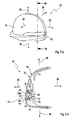
- Figs. 1a to Fig. 5 display constructive details of a first embodiment of a mirror assembly 70 with a turn-indicator light module 10 according to the invention, and Fig. 6 shows a variant of the first embodiment.
- Figs. 1 a, 1 b are described in conjunction with Figs. 2a, 2b .
- Fig. 1 a and 1 b depict a first example embodiment of an external rear view mirror assembly 70 comprising a turn-indicator light module 10.
- the rear view mirror assembly 70 has an opening on one side for receiving a mirror (not shown) in a mirror housing 74 with an outer contour 72 opposite to the mirror.
- Fig. 2a, 2b provide a second perspective view ( Fig. 2a ) of the first embodiment and a cross-sectional cut through the preferred mirror assembly 70 ( Fig. 2b ) of this embodiment.
- Reference numeral 30 refers to a driving direction of a vehicle to which the rear view mirror assembly 70 is attached (i.e. forward direction of the driving vehicle), reference numeral 32 refers to a sideward direction of the rear view mirror assembly 70, which is assigned to an exit of light generated by the turn indicator light module 10.
- Reference numeral 34 indicates the rear view direction.
- Reference numeral 36 refers to an upward direction and reference numeral 38 refers to a downward direction.
- the turn-indicator light module 10 comprises a housing 11 consisting of a rear housing unit 12 and a front housing unit 14 which enclose a number of light emitting sources 18, e.g. a light emitting diode (LED), mounted on a printed circuit board 16 (PCB 16, seen in Fig. 2b ), a reflector unit 20 for reflecting light of the light emitting sources 18. Only one light emitting source 18 can be seen in the view.
- the rear housing unit 12 and the front housing unit 14 can be joined together forming the housing 11.
- the reflector unit has a portion 20 which is provided for an additional light emitting source 42 mounted on a separate PCB 40. Said additional light emitting source 42 is electrically coupled to the PCB 16 by a wire harness 46.
- the front housing unit 14 comprises a lens or light pane portion 22 (in the following called lens), which is flush with the contour 72 of the mirror housing 74 (or may at least follows the contour 72 of the mirror housing 74).
- the front housing unit 14, the rear housing unit 12, the reflector unit 20 and the PCB 16 follow the contour 72 of the mirror housing 74.
- said PCB 16 is mounted in the upper portion of the housing 11, wherein the light emitting source 18 emits light in a downward direction 38.
- the reflector unit 20 has a longitudinal bended and cross-sectional bent reflecting surface 44 adapted to reflect light from a downward direction 38 to said driving 30 and said sideward direction 32.
- the shape of the reflecting surface 44 is, for instance, parabolic, elliptical or the like, as can be seen in Fig. 2b .
- the PCB 16 can also be mounted in the lower portion of the housing 11 (not shown), wherein the light emitting source 18 emits light in a upward direction 36.
- the reflector unit 20 has a longitudinal bent and cross-sectional curved reflecting surface 44 and is in this case adapted to reflect light from an upward direction 36 to said driving 30 and said sideward direction 32.
- a web 20a is arranged at the reflector unit 20 pointing towards the light emitting elements 18 with an opening 21 for each light emitting source 18 for passing light from the light emitting source 18 to the reflector unit 20.
- a major portion of a longitudinal extension 24 of the rear housing unit 12, the front housing unit 14, the reflector unit 20 and said PCB 16 are bend in a way to follow the overall contour 72 of the mirror housing 74.
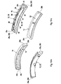
- Fig. 3a shows the components side by side
- Fig. 3b and 3c show a perspective explosion view of the assembly from the rear housing unit side ( Fig. 3b ) and from the front housing unit side ( Fig. 3c ), wherein in Figs. 3b and 3b the PCB 16 is mounted to the reflector unit 20.
- the front housing unit 14 comprises the lens portion 22 and extends from a first end 26b to a second end 28b.
- the next component behind the front housing unit 14 is the reflector unit 20 extending from a first end 26d to a second end 28d with the web 20a comprising openings 21 in conjunction with the positions of the light emitting elements 18 in an assembled state of the housing 11.
- the next component is the PCB 16 extending from a first end 26c to a second end 28c on which the light emitting sources 18 are mounted.
- the PCB 16 is mounted crosswise to the height of the front housing unit 14.
- the last component is the rear housing unit 12 extending from a first end 26a to a second end 26b.
- the rear housing unit 12 provides snap-in connectors 58 which cooperate with the snap-in connectors 76 inside the mirror housing 74 ( Fig. 1a )
- Said components 14, 20, 16 and 12 follow a portion of said outer contour 72 in driving direction 30 of said external rear view mirror assembly 70, wherein the PCB 16 with the light emitting sources 18 is arranged with respect to said reflector unit 20 to emit light indirectly by light reflection of the reflector unit 20 along the major portion of their longitudinal extension 24 through the lens portion 22 of the front housing unit 14 to said driving direction 30 and to a sideward direction 32.
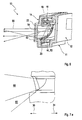
- Figs. 4a-4c illustrate a perspective front view ( Fig. 4a ), a cross-sectional cut ( Fig. 4b ) and a longitudinal cut ( Fig. 4c ) of the housing 11 seen from the front housing unit 12 comprising the lens portion 22.
- the light emitting source 18 in assembled state can be seen in Fig. 4b .
- the light emitting source 18 is hidden behind the web 20a of the reflector unit 20 which is enclosed by the rear housing unit 12 and the front housing unit 14 of the housing 11.
- the reflecting surface 44 of the reflector unit 20 points towards an inner surface to the lens portion 22.
- An outer surface 52 of the lens portion 22 is the exit plane of the light emitted in driving and sideward direction 30, 32.
- Fig. 5 shows a schematic representation of the first embodiment light emission the rear view mirror assembly 70 according to the invention with the turn-indicator light module 10 having an even, smooth reflecting surface 44 of the reflector unit 20.
- Fig. 6 shows a variant with the turn-indicator light module 10 having a ruffled reflecting surface 44 of the reflector unit 20 with grooves 50 in the reflecting surface.
- the light rays 68 reflected from the reflector surface 44, forming indirectly emitted light rays, are indicated by bent arrows.
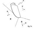
- Fig. 7a , 7b depicts a schematic representation of light emission of the external rear view mirror assembly 70 comprising a turn-indicator light module according to the first example embodiment of the invention in a zoomed view ( Fig 7a ) and in a top view ( Fig. 7b ).
- the indirectly emitted light rays 68 point in driving direction 30 in a generally forward direction.
- a small portion of the light can leave the external rear view mirror assembly 70 in generally downward direction as directly emitted light rays 69.
- the additional light emitting source 42 irradiates light rays 66 in the sideways direction 32.
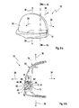
- Figs. 8a to Fig. 12 illustrate various views of a second example embodiment according to the invention.
- Fig. 8a, 8b shows a perspective view ( Fig. 8a ) of the second example embodiment of a rear view mirror assembly 70 according to the invention with turn-indicator light module 10 and a longitudinal cut through said rear view mirror assembly 70 ( Fig. 8b ).
- Most elements have already been explained in detail in conjunction with the first embodiment. In order to avoid unnecessary repetitions, it is referred to the description above for those elements which are not described here in detail. Particularly, the focus of the following description is on the differences between the embodiments.
- the second embodiment has a thick lens or light pane portion 22 (in the following called lens portion) which virtually fills the empty space between the outer surface 52 of the lens portion 22 and the reflector unit 20.
- Fig. 9a, 9b display another perspective view ( Fig. 9a ) of the second embodiment of the rear view mirror assembly 70 and a cross-sectional cut through the rear view mirror assembly 70 ( Fig. 9b ).
- the lens portion 22 fills the empty space between the outer surface 52 of the lens portion 22 and the reflecting surface 44 of the reflector unit 20 leaving only a small air gap 60 between the inner surface 54 of the lens portion 22 and an inner surface 56 of the reflector unit 20.
- the reflector unit 20 is made of massive material like the lens portion 22. Either the inner surface 54 of the lens portion 22 or the inner surface 56 of the reflector unit 20 may by metallized for acting as reflecting surface 44.
- the lens portion 22 has a recess 62 for each light emitting source 18. Light from the light emitting source 18 enters into the lens portion 22 and is reflected from the reflecting surface 44 in the desired direction.
- the reflector unit 20 may now be integral part of the rear housing unit 12 which is also illustrated in Figs. 10a-10c.
- Figs. 10a-10c depict different exploded views from different directions of an assembly sequence of the of the turn-indicator light module 70 according a second example embodiment of the invention.
- Figs. 11 a-11 c show a perspective front view ( Fig. 11 a.), a cross-sectional cut ( Fig. 11 b) and a longitudinal cut ( Fig. 11 c) of the embodiment of the of the turn-indicator light module 70 according the second example embodiment of the invention clearly showing the recess 62 in the lens portion 22 for coupling the light of the light emitting source 18 into the lens portion 22.
- Fig. 12 illustrates a schematic representation of light emission of the turn-indicator light module 70 according a second example embodiment of the invention, indicating the indirectly emitted light rays 68 which are emitted from the light emitting source 18 and reflected at the reflecting surface 44.
Priority Applications (3)
| Application Number | Priority Date | Filing Date | Title |
|---|---|---|---|
| EP09016089.6A EP2340967B2 (de) | 2009-12-29 | 2009-12-29 | Blinkermodul für eine Fahrzeugspiegelanordnung und Fahrzeugspiegelanordnung mit einem Blinkermodul |
| KR1020100133912A KR101268814B1 (ko) | 2009-12-29 | 2010-12-23 | 차량 미러 조립체용 방향 지시등 모듈 및 방향 지시등 모듈을 포함하는 차량 미러 조립체 |
| US12/980,483 US8469563B2 (en) | 2009-12-29 | 2010-12-29 | Turn-indicator light module for a vehicle mirror assembly and vehicle mirror assembly comprising a turn-indicator light module |
Applications Claiming Priority (1)
| Application Number | Priority Date | Filing Date | Title |
|---|---|---|---|
| EP09016089.6A EP2340967B2 (de) | 2009-12-29 | 2009-12-29 | Blinkermodul für eine Fahrzeugspiegelanordnung und Fahrzeugspiegelanordnung mit einem Blinkermodul |
Publications (3)
| Publication Number | Publication Date |
|---|---|
| EP2340967A1 true EP2340967A1 (de) | 2011-07-06 |
| EP2340967B1 EP2340967B1 (de) | 2013-08-28 |
| EP2340967B2 EP2340967B2 (de) | 2016-09-14 |
Family
ID=41718474
Family Applications (1)
| Application Number | Title | Priority Date | Filing Date |
|---|---|---|---|
| EP09016089.6A Active EP2340967B2 (de) | 2009-12-29 | 2009-12-29 | Blinkermodul für eine Fahrzeugspiegelanordnung und Fahrzeugspiegelanordnung mit einem Blinkermodul |
Country Status (3)
| Country | Link |
|---|---|
| US (1) | US8469563B2 (de) |
| EP (1) | EP2340967B2 (de) |
| KR (1) | KR101268814B1 (de) |
Cited By (5)
| Publication number | Priority date | Publication date | Assignee | Title |
|---|---|---|---|---|
| DE102012109492A1 (de) * | 2012-10-05 | 2014-04-10 | Hella Kgaa Hueck & Co. | Beleuchtungseinheit für ein Kraftfahrzeug |
| DE102012109491A1 (de) * | 2012-10-05 | 2014-04-10 | Hella Kgaa Hueck & Co. | Beleuchtungseinheit für ein Kraftfahrzeug |
| ITTO20121039A1 (it) * | 2012-12-03 | 2014-06-04 | Olsa Spa | Fanale laterale |
| WO2016192940A1 (de) * | 2015-05-29 | 2016-12-08 | Hella Kgaa Hueck & Co. | Seitenblinkleuchte für fahrzeuge |
| WO2018167096A1 (en) | 2017-03-13 | 2018-09-20 | Motherson Innovations Company Ltd. | Light emitting mirror bezel |
Families Citing this family (23)
| Publication number | Priority date | Publication date | Assignee | Title |
|---|---|---|---|---|
| US8786704B2 (en) | 2007-08-09 | 2014-07-22 | Donnelly Corporation | Vehicle mirror assembly with wide angle element |
| WO2012133147A1 (ja) * | 2011-03-30 | 2012-10-04 | 株式会社ミツバ | ドアミラー用ターンランプ |
| JP2012243493A (ja) * | 2011-05-18 | 2012-12-10 | Stanley Electric Co Ltd | 車両用信号灯 |
| DE102012108480B3 (de) * | 2012-09-11 | 2014-02-20 | SMR Patents S.à.r.l. | Kopfteil |
| US10744947B2 (en) * | 2012-01-24 | 2020-08-18 | SMR Patents S.à.r.l. | Head section for a rear view device |
| WO2013110122A1 (en) * | 2012-01-24 | 2013-08-01 | SMR Patents S.à.r.l. | Chromium-based reflective coating |
| JP6234157B2 (ja) * | 2013-10-17 | 2017-11-22 | 株式会社小糸製作所 | 車両用灯具 |
| US20150151674A1 (en) * | 2013-12-04 | 2015-06-04 | Chen-Wei Hsu | Rearview mirror with light tube |
| KR101451861B1 (ko) * | 2014-03-14 | 2014-10-16 | 에스엘 주식회사 | 차량용 램프 |
| KR101575471B1 (ko) | 2014-05-13 | 2015-12-07 | 현대자동차주식회사 | 자동차용 인사이드 미러 조립체 |
| JP6293604B2 (ja) * | 2014-07-28 | 2018-03-14 | 株式会社村上開明堂 | ランプ付き車両用アウターミラー |
| CN104456362A (zh) * | 2014-12-10 | 2015-03-25 | 上海康耐司信号设备有限公司 | 一种使用白光led的转向灯及具有该转向灯的汽车 |
| US20160297356A1 (en) * | 2015-04-13 | 2016-10-13 | Ford Global Technologies, Llc | Printed led warning indicator signal |
| EP3165631B1 (de) * | 2015-11-09 | 2019-02-20 | SMR Patents S.à.r.l. | Beschichtete polymersubstrate |
| KR102236476B1 (ko) * | 2015-11-27 | 2021-04-06 | 에스엘 주식회사 | 차량용 램프 |
| US10440249B2 (en) * | 2017-01-13 | 2019-10-08 | Magna Electronics Inc. | Vehicle vision system camera with semi-reflective and semi-transmissive element |
| US10967799B2 (en) * | 2017-04-20 | 2021-04-06 | Motherson Innovations Company Limited | Combined approach lamp and logo lamp |
| US11325536B2 (en) * | 2017-06-13 | 2022-05-10 | Magna Mirrors Of America, Inc. | Vehicle exterior system with light module |
| US11739928B2 (en) | 2017-08-10 | 2023-08-29 | Archangel Device Llc | Safety light |
| AU2018313245B2 (en) * | 2017-08-10 | 2023-02-02 | Archangel Device Llc | Safety light |
| EP3956925A1 (de) * | 2019-04-18 | 2022-02-23 | Lumileds Holding B.V. | Beleuchtungsvorrichtung |
| WO2021116922A1 (en) * | 2019-12-10 | 2021-06-17 | 3M Innovative Properties Company | Powered room air purifier with air-quality visual indicator |
| CN115023370A (zh) | 2020-01-23 | 2022-09-06 | Lg伊诺特有限公司 | 光学组件和具有该光学组件的后视组件 |
Citations (7)
| Publication number | Priority date | Publication date | Assignee | Title |
|---|---|---|---|---|
| DE20011341U1 (de) * | 2000-06-28 | 2000-09-21 | Fer Fahrzeugelektrik Gmbh | Leuchtenbaugruppe |
| DE20114989U1 (de) * | 2001-09-11 | 2001-11-29 | Fer Fahrzeugelektrik Gmbh | Fahrzeugleuchte |
| DE10058659A1 (de) * | 2000-11-25 | 2002-05-29 | Volkswagen Ag | Leuchte für Kraftfahrzeuge, insbesondere Signalleuchte |
| DE10239839A1 (de) * | 2002-08-29 | 2004-03-11 | Volkswagen Ag | Aussenrückspiegel für Fahrzeuge mit einer Signalleuchte |
| US20050243568A1 (en) | 2000-07-12 | 2005-11-03 | Alejandro Rodriguez Barros | Set of parts and assembling method for assembling a rear-view side mirror of a vehicle |
| JP2006205785A (ja) * | 2005-01-25 | 2006-08-10 | Honda Motor Co Ltd | アウトサイドミラー装置 |
| US7225464B2 (en) | 2002-04-03 | 2007-05-29 | Yodlee.Com, Inc. | Method for verifying the identity of a user for session authentication purposes during Web navigation |
Family Cites Families (11)
| Publication number | Priority date | Publication date | Assignee | Title |
|---|---|---|---|---|
| US6511192B1 (en) * | 1999-12-17 | 2003-01-28 | Britax Vision Systems (North America) Inc. | Side view mirror with integral lighting |
| DE10025810B4 (de) † | 2000-05-24 | 2014-01-23 | SMR Patents S.à.r.l. | Leuchteneinheit, insbesondere für Außenrückblickspiegel von Fahrzeugen, vorzugsweise von Kraftfahrzeugen |
| US6769798B2 (en) † | 2002-04-11 | 2004-08-03 | E'sam Co.,. Ltd. | Side mirror cover and cover lamp to be used therefor |
| JP4110989B2 (ja) † | 2003-02-03 | 2008-07-02 | 市光工業株式会社 | ランプ付きアウトサイドミラー装置 |
| JP4433789B2 (ja) † | 2003-12-24 | 2010-03-17 | 市光工業株式会社 | 車両用アウトサイドミラー装置 |
| JP2005190716A (ja) | 2003-12-24 | 2005-07-14 | Ichikoh Ind Ltd | 車両用アウトサイドミラー装置 |
| JP4286674B2 (ja) † | 2004-01-14 | 2009-07-01 | 本田技研工業株式会社 | 車両用灯体制御装置 |
| DE102005012104A1 (de) † | 2005-03-10 | 2006-09-14 | Schefenacker Vision Systems Germany Gmbh | Gehäuse, insbesondere Spiegelgehäuse |
| KR100742616B1 (ko) * | 2006-04-28 | 2007-07-24 | 주식회사 쉐프네커 풍정 | 방향지시등을 겸비한 아웃사이드 미러 |
| JP4930787B2 (ja) † | 2007-07-27 | 2012-05-16 | スタンレー電気株式会社 | 車両用灯具、及び、車両用灯具に用いられる導光レンズ |
| JP5152577B2 (ja) * | 2008-06-09 | 2013-02-27 | スタンレー電気株式会社 | リング状発光体を用いた照明装置 |
-
2009
- 2009-12-29 EP EP09016089.6A patent/EP2340967B2/de active Active
-
2010
- 2010-12-23 KR KR1020100133912A patent/KR101268814B1/ko active IP Right Grant
- 2010-12-29 US US12/980,483 patent/US8469563B2/en active Active
Patent Citations (7)
| Publication number | Priority date | Publication date | Assignee | Title |
|---|---|---|---|---|
| DE20011341U1 (de) * | 2000-06-28 | 2000-09-21 | Fer Fahrzeugelektrik Gmbh | Leuchtenbaugruppe |
| US20050243568A1 (en) | 2000-07-12 | 2005-11-03 | Alejandro Rodriguez Barros | Set of parts and assembling method for assembling a rear-view side mirror of a vehicle |
| DE10058659A1 (de) * | 2000-11-25 | 2002-05-29 | Volkswagen Ag | Leuchte für Kraftfahrzeuge, insbesondere Signalleuchte |
| DE20114989U1 (de) * | 2001-09-11 | 2001-11-29 | Fer Fahrzeugelektrik Gmbh | Fahrzeugleuchte |
| US7225464B2 (en) | 2002-04-03 | 2007-05-29 | Yodlee.Com, Inc. | Method for verifying the identity of a user for session authentication purposes during Web navigation |
| DE10239839A1 (de) * | 2002-08-29 | 2004-03-11 | Volkswagen Ag | Aussenrückspiegel für Fahrzeuge mit einer Signalleuchte |
| JP2006205785A (ja) * | 2005-01-25 | 2006-08-10 | Honda Motor Co Ltd | アウトサイドミラー装置 |
Cited By (11)
| Publication number | Priority date | Publication date | Assignee | Title |
|---|---|---|---|---|
| DE102012109492A1 (de) * | 2012-10-05 | 2014-04-10 | Hella Kgaa Hueck & Co. | Beleuchtungseinheit für ein Kraftfahrzeug |
| DE102012109491A1 (de) * | 2012-10-05 | 2014-04-10 | Hella Kgaa Hueck & Co. | Beleuchtungseinheit für ein Kraftfahrzeug |
| US9671077B2 (en) | 2012-10-05 | 2017-06-06 | Hella Kgaa Hueck & Co. | LED illumination unit having mask and reflector |
| ITTO20121039A1 (it) * | 2012-12-03 | 2014-06-04 | Olsa Spa | Fanale laterale |
| WO2016192940A1 (de) * | 2015-05-29 | 2016-12-08 | Hella Kgaa Hueck & Co. | Seitenblinkleuchte für fahrzeuge |
| CN107735284A (zh) * | 2015-05-29 | 2018-02-23 | 黑拉有限责任两合公司 | 用于车辆的侧面闪光信号灯 |
| US10479268B2 (en) | 2015-05-29 | 2019-11-19 | HELLA GmbH & Co. KGaA | Side-mounted direction indicator for vehicles having a plurality of light sources disposed on a common carrier and an optical unit associated with the plurality of light sources |
| WO2018167096A1 (en) | 2017-03-13 | 2018-09-20 | Motherson Innovations Company Ltd. | Light emitting mirror bezel |
| EP3760486A1 (de) | 2017-03-13 | 2021-01-06 | Motherson Innovations Company Limited | Lichtemittierende spiegeleinfassung |
| EP3845419A1 (de) | 2017-03-13 | 2021-07-07 | Motherson Innovations Company Limited | Lichtemittierender spiegeleinfassung |
| EP4140816A1 (de) | 2017-03-13 | 2023-03-01 | Motherson Innovations Company Ltd. | Multifunktionsrückblickvorrichtung |
Also Published As
| Publication number | Publication date |
|---|---|
| EP2340967B1 (de) | 2013-08-28 |
| KR20110076787A (ko) | 2011-07-06 |
| US20110157907A1 (en) | 2011-06-30 |
| US8469563B2 (en) | 2013-06-25 |
| EP2340967B2 (de) | 2016-09-14 |
| KR101268814B1 (ko) | 2013-06-04 |
Similar Documents
| Publication | Publication Date | Title |
|---|---|---|
| EP2340967B1 (de) | Blinkermodul für eine Fahrzeugspiegelanordnung und Fahrzeugspiegelanordnung mit einem Blinkermodul | |
| EP3418626B1 (de) | Scheinwerfer und fahrzeug damit | |
| CN102235628B (zh) | 汽车用光导装置 | |
| US20150233539A1 (en) | Motor vehicle lighting and/or signaling device | |
| EP2277741B1 (de) | Rückspiegel mit Lichtwellenleiter-Wendesignalanzeiger | |
| US11320112B2 (en) | Optical device for an automobile vehicle | |
| EP3212463B1 (de) | Lampenanordnung für ein fahrzeug | |
| JP2007022325A (ja) | 車両用ドアの照明装置 | |
| CN105556199A (zh) | 具有连续变化的光均匀性的用于机动车辆的照明模块 | |
| US20110032721A1 (en) | Vehicular lamp | |
| WO2005028250A1 (en) | Vehicular light assembly | |
| EP1559614B1 (de) | Aussenrückspiegel für Fahrzeuge und Beleuchtungseinrichtung für einen solchen Aussenrückspiegel | |
| US7513665B2 (en) | Headlamp module and headlamp assembly with internally reflecting translucent member | |
| KR20200080105A (ko) | Led 차량용 선형 발광 모듈 | |
| JP2009526372A (ja) | 直接照射車両ランプ | |
| CN218505742U (zh) | 信号灯的发光结构和具有其的车辆 | |
| JP2004299611A (ja) | 後視鏡装置 | |
| US11867373B2 (en) | Bendable lighting device | |
| JP7483523B2 (ja) | 車両用灯具 | |
| WO2020246333A1 (ja) | 二輪車用灯具 | |
| US20230175667A1 (en) | Mini or micro led-based light module configured to perform plural light functions seamlessly with different light guides in unitary assembly | |
| CN106195844B (zh) | 一种汽车内饰灯 | |
| JP2021174570A (ja) | 車両用灯具 | |
| JP2023057694A (ja) | 車両用灯具 | |
| WO2021247931A1 (en) | Optically embedded flexible filament |
Legal Events
| Date | Code | Title | Description |
|---|---|---|---|
| PUAI | Public reference made under article 153(3) epc to a published international application that has entered the european phase |
Free format text: ORIGINAL CODE: 0009012 |
|
| 17P | Request for examination filed |
Effective date: 20100825 |
|
| AK | Designated contracting states |
Kind code of ref document: A1 Designated state(s): AT BE BG CH CY CZ DE DK EE ES FI FR GB GR HR HU IE IS IT LI LT LU LV MC MK MT NL NO PL PT RO SE SI SK SM TR |
|
| AX | Request for extension of the european patent |
Extension state: AL BA RS |
|
| GRAP | Despatch of communication of intention to grant a patent |
Free format text: ORIGINAL CODE: EPIDOSNIGR1 |
|
| RIC1 | Information provided on ipc code assigned before grant |
Ipc: B60Q 1/26 20060101ALI20130410BHEP Ipc: B60R 1/12 20060101AFI20130410BHEP |
|
| INTG | Intention to grant announced |
Effective date: 20130506 |
|
| RIN1 | Information on inventor provided before grant (corrected) |
Inventor name: PARK, KWANG-RYEOL Inventor name: HWANG, HYOK-JOO |
|
| GRAS | Grant fee paid |
Free format text: ORIGINAL CODE: EPIDOSNIGR3 |
|
| GRAA | (expected) grant |
Free format text: ORIGINAL CODE: 0009210 |
|
| AK | Designated contracting states |
Kind code of ref document: B1 Designated state(s): AT BE BG CH CY CZ DE DK EE ES FI FR GB GR HR HU IE IS IT LI LT LU LV MC MK MT NL NO PL PT RO SE SI SK SM TR |
|
| REG | Reference to a national code |
Ref country code: GB Ref legal event code: FG4D |
|
| REG | Reference to a national code |
Ref country code: CH Ref legal event code: EP |
|
| REG | Reference to a national code |
Ref country code: AT Ref legal event code: REF Ref document number: 629132 Country of ref document: AT Kind code of ref document: T Effective date: 20130915 |
|
| REG | Reference to a national code |
Ref country code: IE Ref legal event code: FG4D |
|
| REG | Reference to a national code |
Ref country code: DE Ref legal event code: R096 Ref document number: 602009018318 Country of ref document: DE Effective date: 20131024 |
|
| REG | Reference to a national code |
Ref country code: AT Ref legal event code: MK05 Ref document number: 629132 Country of ref document: AT Kind code of ref document: T Effective date: 20130828 |
|
| REG | Reference to a national code |
Ref country code: LT Ref legal event code: MG4D |
|
| REG | Reference to a national code |
Ref country code: NL Ref legal event code: VDEP Effective date: 20130828 |
|
| PG25 | Lapsed in a contracting state [announced via postgrant information from national office to epo] |
Ref country code: HR Free format text: LAPSE BECAUSE OF FAILURE TO SUBMIT A TRANSLATION OF THE DESCRIPTION OR TO PAY THE FEE WITHIN THE PRESCRIBED TIME-LIMIT Effective date: 20130828 Ref country code: NO Free format text: LAPSE BECAUSE OF FAILURE TO SUBMIT A TRANSLATION OF THE DESCRIPTION OR TO PAY THE FEE WITHIN THE PRESCRIBED TIME-LIMIT Effective date: 20131128 Ref country code: IS Free format text: LAPSE BECAUSE OF FAILURE TO SUBMIT A TRANSLATION OF THE DESCRIPTION OR TO PAY THE FEE WITHIN THE PRESCRIBED TIME-LIMIT Effective date: 20131228 Ref country code: LT Free format text: LAPSE BECAUSE OF FAILURE TO SUBMIT A TRANSLATION OF THE DESCRIPTION OR TO PAY THE FEE WITHIN THE PRESCRIBED TIME-LIMIT Effective date: 20130828 Ref country code: CY Free format text: LAPSE BECAUSE OF FAILURE TO SUBMIT A TRANSLATION OF THE DESCRIPTION OR TO PAY THE FEE WITHIN THE PRESCRIBED TIME-LIMIT Effective date: 20130724 Ref country code: PT Free format text: LAPSE BECAUSE OF FAILURE TO SUBMIT A TRANSLATION OF THE DESCRIPTION OR TO PAY THE FEE WITHIN THE PRESCRIBED TIME-LIMIT Effective date: 20131230 Ref country code: SE Free format text: LAPSE BECAUSE OF FAILURE TO SUBMIT A TRANSLATION OF THE DESCRIPTION OR TO PAY THE FEE WITHIN THE PRESCRIBED TIME-LIMIT Effective date: 20130828 Ref country code: AT Free format text: LAPSE BECAUSE OF FAILURE TO SUBMIT A TRANSLATION OF THE DESCRIPTION OR TO PAY THE FEE WITHIN THE PRESCRIBED TIME-LIMIT Effective date: 20130828 |
|
| REG | Reference to a national code |
Ref country code: NL Ref legal event code: VDEP Effective date: 20130828 |
|
| PG25 | Lapsed in a contracting state [announced via postgrant information from national office to epo] |
Ref country code: PL Free format text: LAPSE BECAUSE OF FAILURE TO SUBMIT A TRANSLATION OF THE DESCRIPTION OR TO PAY THE FEE WITHIN THE PRESCRIBED TIME-LIMIT Effective date: 20130828 Ref country code: GR Free format text: LAPSE BECAUSE OF FAILURE TO SUBMIT A TRANSLATION OF THE DESCRIPTION OR TO PAY THE FEE WITHIN THE PRESCRIBED TIME-LIMIT Effective date: 20131129 Ref country code: FI Free format text: LAPSE BECAUSE OF FAILURE TO SUBMIT A TRANSLATION OF THE DESCRIPTION OR TO PAY THE FEE WITHIN THE PRESCRIBED TIME-LIMIT Effective date: 20130828 Ref country code: SI Free format text: LAPSE BECAUSE OF FAILURE TO SUBMIT A TRANSLATION OF THE DESCRIPTION OR TO PAY THE FEE WITHIN THE PRESCRIBED TIME-LIMIT Effective date: 20130828 Ref country code: BE Free format text: LAPSE BECAUSE OF FAILURE TO SUBMIT A TRANSLATION OF THE DESCRIPTION OR TO PAY THE FEE WITHIN THE PRESCRIBED TIME-LIMIT Effective date: 20130828 Ref country code: LV Free format text: LAPSE BECAUSE OF FAILURE TO SUBMIT A TRANSLATION OF THE DESCRIPTION OR TO PAY THE FEE WITHIN THE PRESCRIBED TIME-LIMIT Effective date: 20130828 |
|
| PG25 | Lapsed in a contracting state [announced via postgrant information from national office to epo] |
Ref country code: CY Free format text: LAPSE BECAUSE OF FAILURE TO SUBMIT A TRANSLATION OF THE DESCRIPTION OR TO PAY THE FEE WITHIN THE PRESCRIBED TIME-LIMIT Effective date: 20130828 |
|
| PG25 | Lapsed in a contracting state [announced via postgrant information from national office to epo] |
Ref country code: DK Free format text: LAPSE BECAUSE OF FAILURE TO SUBMIT A TRANSLATION OF THE DESCRIPTION OR TO PAY THE FEE WITHIN THE PRESCRIBED TIME-LIMIT Effective date: 20130828 Ref country code: EE Free format text: LAPSE BECAUSE OF FAILURE TO SUBMIT A TRANSLATION OF THE DESCRIPTION OR TO PAY THE FEE WITHIN THE PRESCRIBED TIME-LIMIT Effective date: 20130828 Ref country code: SK Free format text: LAPSE BECAUSE OF FAILURE TO SUBMIT A TRANSLATION OF THE DESCRIPTION OR TO PAY THE FEE WITHIN THE PRESCRIBED TIME-LIMIT Effective date: 20130828 Ref country code: RO Free format text: LAPSE BECAUSE OF FAILURE TO SUBMIT A TRANSLATION OF THE DESCRIPTION OR TO PAY THE FEE WITHIN THE PRESCRIBED TIME-LIMIT Effective date: 20130828 Ref country code: CZ Free format text: LAPSE BECAUSE OF FAILURE TO SUBMIT A TRANSLATION OF THE DESCRIPTION OR TO PAY THE FEE WITHIN THE PRESCRIBED TIME-LIMIT Effective date: 20130828 Ref country code: NL Free format text: LAPSE BECAUSE OF FAILURE TO SUBMIT A TRANSLATION OF THE DESCRIPTION OR TO PAY THE FEE WITHIN THE PRESCRIBED TIME-LIMIT Effective date: 20130828 |
|
| PG25 | Lapsed in a contracting state [announced via postgrant information from national office to epo] |
Ref country code: IT Free format text: LAPSE BECAUSE OF FAILURE TO SUBMIT A TRANSLATION OF THE DESCRIPTION OR TO PAY THE FEE WITHIN THE PRESCRIBED TIME-LIMIT Effective date: 20130828 Ref country code: ES Free format text: LAPSE BECAUSE OF FAILURE TO SUBMIT A TRANSLATION OF THE DESCRIPTION OR TO PAY THE FEE WITHIN THE PRESCRIBED TIME-LIMIT Effective date: 20130828 |
|
| PLBI | Opposition filed |
Free format text: ORIGINAL CODE: 0009260 |
|
| PLAX | Notice of opposition and request to file observation + time limit sent |
Free format text: ORIGINAL CODE: EPIDOSNOBS2 |
|
| 26 | Opposition filed |
Opponent name: VOLKSWAGEN AKTIENGESELLSCHAFT Effective date: 20140527 |
|
| REG | Reference to a national code |
Ref country code: CH Ref legal event code: PL |
|
| REG | Reference to a national code |
Ref country code: DE Ref legal event code: R026 Ref document number: 602009018318 Country of ref document: DE Effective date: 20140527 |
|
| PG25 | Lapsed in a contracting state [announced via postgrant information from national office to epo] |
Ref country code: LU Free format text: LAPSE BECAUSE OF FAILURE TO SUBMIT A TRANSLATION OF THE DESCRIPTION OR TO PAY THE FEE WITHIN THE PRESCRIBED TIME-LIMIT Effective date: 20131229 Ref country code: MC Free format text: LAPSE BECAUSE OF FAILURE TO SUBMIT A TRANSLATION OF THE DESCRIPTION OR TO PAY THE FEE WITHIN THE PRESCRIBED TIME-LIMIT Effective date: 20130828 |
|
| REG | Reference to a national code |
Ref country code: IE Ref legal event code: MM4A |
|
| PG25 | Lapsed in a contracting state [announced via postgrant information from national office to epo] |
Ref country code: IE Free format text: LAPSE BECAUSE OF NON-PAYMENT OF DUE FEES Effective date: 20131229 Ref country code: CH Free format text: LAPSE BECAUSE OF NON-PAYMENT OF DUE FEES Effective date: 20131231 Ref country code: LI Free format text: LAPSE BECAUSE OF NON-PAYMENT OF DUE FEES Effective date: 20131231 |
|
| PLBB | Reply of patent proprietor to notice(s) of opposition received |
Free format text: ORIGINAL CODE: EPIDOSNOBS3 |
|
| PG25 | Lapsed in a contracting state [announced via postgrant information from national office to epo] |
Ref country code: SM Free format text: LAPSE BECAUSE OF FAILURE TO SUBMIT A TRANSLATION OF THE DESCRIPTION OR TO PAY THE FEE WITHIN THE PRESCRIBED TIME-LIMIT Effective date: 20130828 |
|
| PG25 | Lapsed in a contracting state [announced via postgrant information from national office to epo] |
Ref country code: TR Free format text: LAPSE BECAUSE OF FAILURE TO SUBMIT A TRANSLATION OF THE DESCRIPTION OR TO PAY THE FEE WITHIN THE PRESCRIBED TIME-LIMIT Effective date: 20130828 |
|
| PG25 | Lapsed in a contracting state [announced via postgrant information from national office to epo] |
Ref country code: MK Free format text: LAPSE BECAUSE OF FAILURE TO SUBMIT A TRANSLATION OF THE DESCRIPTION OR TO PAY THE FEE WITHIN THE PRESCRIBED TIME-LIMIT Effective date: 20130828 Ref country code: HU Free format text: LAPSE BECAUSE OF FAILURE TO SUBMIT A TRANSLATION OF THE DESCRIPTION OR TO PAY THE FEE WITHIN THE PRESCRIBED TIME-LIMIT; INVALID AB INITIO Effective date: 20091229 Ref country code: BG Free format text: LAPSE BECAUSE OF FAILURE TO SUBMIT A TRANSLATION OF THE DESCRIPTION OR TO PAY THE FEE WITHIN THE PRESCRIBED TIME-LIMIT Effective date: 20130828 |
|
| PG25 | Lapsed in a contracting state [announced via postgrant information from national office to epo] |
Ref country code: MT Free format text: LAPSE BECAUSE OF FAILURE TO SUBMIT A TRANSLATION OF THE DESCRIPTION OR TO PAY THE FEE WITHIN THE PRESCRIBED TIME-LIMIT Effective date: 20130828 |
|
| REG | Reference to a national code |
Ref country code: FR Ref legal event code: PLFP Year of fee payment: 7 |
|
| PUAH | Patent maintained in amended form |
Free format text: ORIGINAL CODE: 0009272 |
|
| STAA | Information on the status of an ep patent application or granted ep patent |
Free format text: STATUS: PATENT MAINTAINED AS AMENDED |
|
| 27A | Patent maintained in amended form |
Effective date: 20160914 |
|
| AK | Designated contracting states |
Kind code of ref document: B2 Designated state(s): AT BE BG CH CY CZ DE DK EE ES FI FR GB GR HR HU IE IS IT LI LT LU LV MC MK MT NL NO PL PT RO SE SI SK SM TR |
|
| REG | Reference to a national code |
Ref country code: DE Ref legal event code: R102 Ref document number: 602009018318 Country of ref document: DE |
|
| REG | Reference to a national code |
Ref country code: FR Ref legal event code: PLFP Year of fee payment: 8 |
|
| REG | Reference to a national code |
Ref country code: FR Ref legal event code: PLFP Year of fee payment: 9 |
|
| REG | Reference to a national code |
Ref country code: DE Ref legal event code: R084 Ref document number: 602009018318 Country of ref document: DE |
|
| P01 | Opt-out of the competence of the unified patent court (upc) registered |
Effective date: 20230616 |
|
| PGFP | Annual fee paid to national office [announced via postgrant information from national office to epo] |
Ref country code: GB Payment date: 20231220 Year of fee payment: 15 |
|
| PGFP | Annual fee paid to national office [announced via postgrant information from national office to epo] |
Ref country code: FR Payment date: 20231220 Year of fee payment: 15 Ref country code: DE Payment date: 20231214 Year of fee payment: 15 |