EP2328258A2 - Tragbare Vorrichtung zum Anzeigen der Batterieladungsinformation und Batterieladungsinformationsanzeigesystem - Google Patents
Tragbare Vorrichtung zum Anzeigen der Batterieladungsinformation und Batterieladungsinformationsanzeigesystem Download PDFInfo
- Publication number
- EP2328258A2 EP2328258A2 EP10193113A EP10193113A EP2328258A2 EP 2328258 A2 EP2328258 A2 EP 2328258A2 EP 10193113 A EP10193113 A EP 10193113A EP 10193113 A EP10193113 A EP 10193113A EP 2328258 A2 EP2328258 A2 EP 2328258A2
- Authority
- EP
- European Patent Office
- Prior art keywords
- charge
- battery
- charge information
- unit
- information
- Prior art date
- Legal status (The legal status is an assumption and is not a legal conclusion. Google has not performed a legal analysis and makes no representation as to the accuracy of the status listed.)
- Granted
Links
- 230000005540 biological transmission Effects 0.000 claims description 35
- 238000000034 method Methods 0.000 description 22
- 230000001413 cellular effect Effects 0.000 description 3
- HBBGRARXTFLTSG-UHFFFAOYSA-N Lithium ion Chemical compound [Li+] HBBGRARXTFLTSG-UHFFFAOYSA-N 0.000 description 2
- 238000010586 diagram Methods 0.000 description 2
- 229910001416 lithium ion Inorganic materials 0.000 description 2
- 239000011150 reinforced concrete Substances 0.000 description 2
- 239000004065 semiconductor Substances 0.000 description 2
- CURLTUGMZLYLDI-UHFFFAOYSA-N Carbon dioxide Chemical compound O=C=O CURLTUGMZLYLDI-UHFFFAOYSA-N 0.000 description 1
- WHXSMMKQMYFTQS-UHFFFAOYSA-N Lithium Chemical compound [Li] WHXSMMKQMYFTQS-UHFFFAOYSA-N 0.000 description 1
- 229910002090 carbon oxide Inorganic materials 0.000 description 1
- 239000013078 crystal Substances 0.000 description 1
- 230000005674 electromagnetic induction Effects 0.000 description 1
- 239000007788 liquid Substances 0.000 description 1
- 229910052744 lithium Inorganic materials 0.000 description 1
- 238000011084 recovery Methods 0.000 description 1
- 230000004044 response Effects 0.000 description 1
- 229920006395 saturated elastomer Polymers 0.000 description 1
Images


Classifications
-
- B—PERFORMING OPERATIONS; TRANSPORTING
- B60—VEHICLES IN GENERAL
- B60L—PROPULSION OF ELECTRICALLY-PROPELLED VEHICLES; SUPPLYING ELECTRIC POWER FOR AUXILIARY EQUIPMENT OF ELECTRICALLY-PROPELLED VEHICLES; ELECTRODYNAMIC BRAKE SYSTEMS FOR VEHICLES IN GENERAL; MAGNETIC SUSPENSION OR LEVITATION FOR VEHICLES; MONITORING OPERATING VARIABLES OF ELECTRICALLY-PROPELLED VEHICLES; ELECTRIC SAFETY DEVICES FOR ELECTRICALLY-PROPELLED VEHICLES
- B60L53/00—Methods of charging batteries, specially adapted for electric vehicles; Charging stations or on-board charging equipment therefor; Exchange of energy storage elements in electric vehicles
- B60L53/60—Monitoring or controlling charging stations
- B60L53/68—Off-site monitoring or control, e.g. remote control
-
- H—ELECTRICITY
- H04—ELECTRIC COMMUNICATION TECHNIQUE
- H04B—TRANSMISSION
- H04B7/00—Radio transmission systems, i.e. using radiation field
- H04B7/24—Radio transmission systems, i.e. using radiation field for communication between two or more posts
-
- B—PERFORMING OPERATIONS; TRANSPORTING
- B60—VEHICLES IN GENERAL
- B60K—ARRANGEMENT OR MOUNTING OF PROPULSION UNITS OR OF TRANSMISSIONS IN VEHICLES; ARRANGEMENT OR MOUNTING OF PLURAL DIVERSE PRIME-MOVERS IN VEHICLES; AUXILIARY DRIVES FOR VEHICLES; INSTRUMENTATION OR DASHBOARDS FOR VEHICLES; ARRANGEMENTS IN CONNECTION WITH COOLING, AIR INTAKE, GAS EXHAUST OR FUEL SUPPLY OF PROPULSION UNITS IN VEHICLES
- B60K35/00—Instruments specially adapted for vehicles; Arrangement of instruments in or on vehicles
- B60K35/60—Instruments characterised by their location or relative disposition in or on vehicles
-
- G—PHYSICS
- G01—MEASURING; TESTING
- G01R—MEASURING ELECTRIC VARIABLES; MEASURING MAGNETIC VARIABLES
- G01R31/00—Arrangements for testing electric properties; Arrangements for locating electric faults; Arrangements for electrical testing characterised by what is being tested not provided for elsewhere
- G01R31/36—Arrangements for testing, measuring or monitoring the electrical condition of accumulators or electric batteries, e.g. capacity or state of charge [SoC]
- G01R31/371—Arrangements for testing, measuring or monitoring the electrical condition of accumulators or electric batteries, e.g. capacity or state of charge [SoC] with remote indication, e.g. on external chargers
-
- H—ELECTRICITY
- H02—GENERATION; CONVERSION OR DISTRIBUTION OF ELECTRIC POWER
- H02J—CIRCUIT ARRANGEMENTS OR SYSTEMS FOR SUPPLYING OR DISTRIBUTING ELECTRIC POWER; SYSTEMS FOR STORING ELECTRIC ENERGY
- H02J7/00—Circuit arrangements for charging or depolarising batteries or for supplying loads from batteries
- H02J7/0047—Circuit arrangements for charging or depolarising batteries or for supplying loads from batteries with monitoring or indicating devices or circuits
- H02J7/0048—Detection of remaining charge capacity or state of charge [SOC]
-
- B—PERFORMING OPERATIONS; TRANSPORTING
- B60—VEHICLES IN GENERAL
- B60L—PROPULSION OF ELECTRICALLY-PROPELLED VEHICLES; SUPPLYING ELECTRIC POWER FOR AUXILIARY EQUIPMENT OF ELECTRICALLY-PROPELLED VEHICLES; ELECTRODYNAMIC BRAKE SYSTEMS FOR VEHICLES IN GENERAL; MAGNETIC SUSPENSION OR LEVITATION FOR VEHICLES; MONITORING OPERATING VARIABLES OF ELECTRICALLY-PROPELLED VEHICLES; ELECTRIC SAFETY DEVICES FOR ELECTRICALLY-PROPELLED VEHICLES
- B60L2250/00—Driver interactions
- B60L2250/16—Driver interactions by display
-
- G—PHYSICS
- G01—MEASURING; TESTING
- G01R—MEASURING ELECTRIC VARIABLES; MEASURING MAGNETIC VARIABLES
- G01R31/00—Arrangements for testing electric properties; Arrangements for locating electric faults; Arrangements for electrical testing characterised by what is being tested not provided for elsewhere
- G01R31/005—Testing of electric installations on transport means
- G01R31/006—Testing of electric installations on transport means on road vehicles, e.g. automobiles or trucks
- G01R31/007—Testing of electric installations on transport means on road vehicles, e.g. automobiles or trucks using microprocessors or computers
-
- Y—GENERAL TAGGING OF NEW TECHNOLOGICAL DEVELOPMENTS; GENERAL TAGGING OF CROSS-SECTIONAL TECHNOLOGIES SPANNING OVER SEVERAL SECTIONS OF THE IPC; TECHNICAL SUBJECTS COVERED BY FORMER USPC CROSS-REFERENCE ART COLLECTIONS [XRACs] AND DIGESTS
- Y02—TECHNOLOGIES OR APPLICATIONS FOR MITIGATION OR ADAPTATION AGAINST CLIMATE CHANGE
- Y02T—CLIMATE CHANGE MITIGATION TECHNOLOGIES RELATED TO TRANSPORTATION
- Y02T10/00—Road transport of goods or passengers
- Y02T10/60—Other road transportation technologies with climate change mitigation effect
- Y02T10/70—Energy storage systems for electromobility, e.g. batteries
-
- Y—GENERAL TAGGING OF NEW TECHNOLOGICAL DEVELOPMENTS; GENERAL TAGGING OF CROSS-SECTIONAL TECHNOLOGIES SPANNING OVER SEVERAL SECTIONS OF THE IPC; TECHNICAL SUBJECTS COVERED BY FORMER USPC CROSS-REFERENCE ART COLLECTIONS [XRACs] AND DIGESTS
- Y02—TECHNOLOGIES OR APPLICATIONS FOR MITIGATION OR ADAPTATION AGAINST CLIMATE CHANGE
- Y02T—CLIMATE CHANGE MITIGATION TECHNOLOGIES RELATED TO TRANSPORTATION
- Y02T10/00—Road transport of goods or passengers
- Y02T10/60—Other road transportation technologies with climate change mitigation effect
- Y02T10/7072—Electromobility specific charging systems or methods for batteries, ultracapacitors, supercapacitors or double-layer capacitors
-
- Y—GENERAL TAGGING OF NEW TECHNOLOGICAL DEVELOPMENTS; GENERAL TAGGING OF CROSS-SECTIONAL TECHNOLOGIES SPANNING OVER SEVERAL SECTIONS OF THE IPC; TECHNICAL SUBJECTS COVERED BY FORMER USPC CROSS-REFERENCE ART COLLECTIONS [XRACs] AND DIGESTS
- Y02—TECHNOLOGIES OR APPLICATIONS FOR MITIGATION OR ADAPTATION AGAINST CLIMATE CHANGE
- Y02T—CLIMATE CHANGE MITIGATION TECHNOLOGIES RELATED TO TRANSPORTATION
- Y02T10/00—Road transport of goods or passengers
- Y02T10/80—Technologies aiming to reduce greenhouse gasses emissions common to all road transportation technologies
- Y02T10/84—Data processing systems or methods, management, administration
-
- Y—GENERAL TAGGING OF NEW TECHNOLOGICAL DEVELOPMENTS; GENERAL TAGGING OF CROSS-SECTIONAL TECHNOLOGIES SPANNING OVER SEVERAL SECTIONS OF THE IPC; TECHNICAL SUBJECTS COVERED BY FORMER USPC CROSS-REFERENCE ART COLLECTIONS [XRACs] AND DIGESTS
- Y02—TECHNOLOGIES OR APPLICATIONS FOR MITIGATION OR ADAPTATION AGAINST CLIMATE CHANGE
- Y02T—CLIMATE CHANGE MITIGATION TECHNOLOGIES RELATED TO TRANSPORTATION
- Y02T90/00—Enabling technologies or technologies with a potential or indirect contribution to GHG emissions mitigation
- Y02T90/10—Technologies relating to charging of electric vehicles
- Y02T90/12—Electric charging stations
-
- Y—GENERAL TAGGING OF NEW TECHNOLOGICAL DEVELOPMENTS; GENERAL TAGGING OF CROSS-SECTIONAL TECHNOLOGIES SPANNING OVER SEVERAL SECTIONS OF THE IPC; TECHNICAL SUBJECTS COVERED BY FORMER USPC CROSS-REFERENCE ART COLLECTIONS [XRACs] AND DIGESTS
- Y02—TECHNOLOGIES OR APPLICATIONS FOR MITIGATION OR ADAPTATION AGAINST CLIMATE CHANGE
- Y02T—CLIMATE CHANGE MITIGATION TECHNOLOGIES RELATED TO TRANSPORTATION
- Y02T90/00—Enabling technologies or technologies with a potential or indirect contribution to GHG emissions mitigation
- Y02T90/10—Technologies relating to charging of electric vehicles
- Y02T90/14—Plug-in electric vehicles
-
- Y—GENERAL TAGGING OF NEW TECHNOLOGICAL DEVELOPMENTS; GENERAL TAGGING OF CROSS-SECTIONAL TECHNOLOGIES SPANNING OVER SEVERAL SECTIONS OF THE IPC; TECHNICAL SUBJECTS COVERED BY FORMER USPC CROSS-REFERENCE ART COLLECTIONS [XRACs] AND DIGESTS
- Y02—TECHNOLOGIES OR APPLICATIONS FOR MITIGATION OR ADAPTATION AGAINST CLIMATE CHANGE
- Y02T—CLIMATE CHANGE MITIGATION TECHNOLOGIES RELATED TO TRANSPORTATION
- Y02T90/00—Enabling technologies or technologies with a potential or indirect contribution to GHG emissions mitigation
- Y02T90/10—Technologies relating to charging of electric vehicles
- Y02T90/16—Information or communication technologies improving the operation of electric vehicles
- Y02T90/167—Systems integrating technologies related to power network operation and communication or information technologies for supporting the interoperability of electric or hybrid vehicles, i.e. smartgrids as interface for battery charging of electric vehicles [EV] or hybrid vehicles [HEV]
-
- Y—GENERAL TAGGING OF NEW TECHNOLOGICAL DEVELOPMENTS; GENERAL TAGGING OF CROSS-SECTIONAL TECHNOLOGIES SPANNING OVER SEVERAL SECTIONS OF THE IPC; TECHNICAL SUBJECTS COVERED BY FORMER USPC CROSS-REFERENCE ART COLLECTIONS [XRACs] AND DIGESTS
- Y04—INFORMATION OR COMMUNICATION TECHNOLOGIES HAVING AN IMPACT ON OTHER TECHNOLOGY AREAS
- Y04S—SYSTEMS INTEGRATING TECHNOLOGIES RELATED TO POWER NETWORK OPERATION, COMMUNICATION OR INFORMATION TECHNOLOGIES FOR IMPROVING THE ELECTRICAL POWER GENERATION, TRANSMISSION, DISTRIBUTION, MANAGEMENT OR USAGE, i.e. SMART GRIDS
- Y04S30/00—Systems supporting specific end-user applications in the sector of transportation
- Y04S30/10—Systems supporting the interoperability of electric or hybrid vehicles
- Y04S30/12—Remote or cooperative charging
Definitions
- the present invention relates to a portable device for displaying charge information, which for example displays a remaining amount of a battery for a vehicle, and also relates to a charge information display system made up of the portable device and a controller.
- environment-responsive cars such as hybrid cars and electronic cars have attracted attention in the automobile industry.
- the hybrid car is a car powered by an electronic motor besides a gasoline engine.
- the electronic car is a car powered by the electric motor alone.
- these environment-responsive cars can suppress consumption of gasoline and emission of carbon oxide, and have thus been expected to prevail as new-generation cars that contribute to protection of the global environment.
- a battery such as a lithium-ion battery is used as a driving source of the electric motor.
- This battery can be externally charged.
- the method for charging the battery there are methods such as a method for performing charging directly from a domestic power supply, and a method for performing charging through the use of a fast charger installed in a shopping mall or the like.
- charge information on a battery such as a remaining amount thereof can be checked whenever necessary, the battery can be charged at the time of need, which is convenient for a user.
- systems have hitherto been proposed in which charge information on a battery is notified from a device mounted with the battery to a portable terminal or the like (e.g. see Japanese Unexamined Patent Publication No. 2009-54302 , Japanese Unexamined Patent Publication No. 2007-57273 , and Japanese Unexamined Patent Publication No. 2009-177509 ).
- Japanese Unexamined Patent Publication No. 2009-54302 describes that, whether or not a battery is normal or whether or not display of detailed history data on the battery is necessary is determined based upon data from a battery-state determining device, and only when the display of the history data is determined as necessary, the data is displayed in externally located another section.
- Japanese Unexamined Patent Publication No. 2007-57273 describes that, when a wireless slave, connected to terminal equipment and driven by a battery, receives an inquiry signal from a portable terminal for communicating information with the terminal equipment, the slave transmits a remaining-amount signal indicating a remaining amount of the battery to the portable terminal device.
- Japanese Unexamined Patent Publication No. 2009-177509 describes that, when a decrease in remaining amount of a battery for a cellular phone to a reference value is detected, a remaining-amount notification signal is transmitted from the cellular phone to a subscriber data managing unit, and when the remaining amount of the battery recovers by charging, a recovery signal is transmitted from the cellular phone to the subscriber data managing unit.
- a system in which information such as a battery remaining amount is wirelessly transmitted from a controller mounted in the vehicle to a portable device, and the information is displayed in a display section of the portable device.
- the user may leave his or her car for the purpose of shopping or the like. Then, due to the mall being a reinforced concrete building, radio waves are blocked between the portable device owned by the user and the controller of the vehicle, which prevents communication therebetween. In this case, since the portable device cannot obtain charge information on the battery from the controller, the charge information is not displayed in the display section. This makes it impossible for the user to know a current battery remaining amount, time before completion of charging, and the like, which is inconvenient.
- An object of the present invention is to provide a portable device for displaying charge information and a charge information display system which offer benefits to a user by displaying charge information and the like based upon predictions even in the case of a portable device and a controller being unable to communicate with each other.
- a portable device for displaying charge information includes: a transmission unit intended to wirelessly transmit a signal, requesting charge information on a battery, to a controller; a reception unit for wirelessly receiving the charge information from the controller; a storage unit for storing charge information received by this reception unit; and a display unit for displaying charge information stored into this storage unit, wherein a charging start time (or charged amount) stored in the storage unit may be displayed in the display unit when the reception unit cannot receive charge information from the controller after transmitting a signal requesting charge information from the transmission unit.
- the device further includes a charge prediction information calculating unit.
- the charge prediction information calculating unit is intended to calculate prediction information regarding a state-of-charge of the battery based upon charge information stored in the storage unit when the reception unit cannot receive charge information from the controller after transmitting a signal requesting charge information from the transmission unit. This prediction information is displayed in the display unit.
- the charge prediction information calculating unit calculates prediction information regarding a state-of-charge of the battery on the portable device side. It is thus possible, by displaying the prediction information in the display unit of the portable device, to notify the user of information with certain accuracy regarding, for example, a battery remaining amount and time before completion of charging.
- the reception unit is intended to receive charge characteristic data on the battery from the controller.
- the charge characteristic data received by the reception unit is stored into the storage unit.
- the charge prediction information calculating unit is then intended to calculate prediction information based upon charge information and charge characteristic data which are stored in the storage unit.
- the charge prediction information calculating unit is intended to calculate prediction information based upon a charge characteristic obtained from the controller at the point of charging a battery, whereby it is possible to obtain highly accurate prediction information with a state, characteristics, surroundings and the like of the battery during charging taken into consideration.
- the charge prediction information calculating unit is intended to calculate prediction information including a predicted remaining amount of the battery and predicted time before completion of charging.
- the portable device for displaying charge information according to the first aspect may further include a first determination unit for determining whether or not a predetermined period has elapsed from past receipt of charge information when the reception unit is unable to receive charge information from the controller after transmitting a signal requesting charge information from the transmission unit. In this case, when it is determined by the first determination unit that the predetermined period has elapsed, past charge information stored in the storage unit is displayed in the display unit.
- a second determination unit may also be included which determines whether or not charge information received in the past is stored in the storage unit. In this case, when it is determined by the first determination unit that the predetermined period has not elapsed and it is determined by the second determination unit that the charge information is stored in the storage unit, the charge prediction information calculating unit is intended to calculate the prediction information.
- a charge information display system is made up of a controller, and a portable device for displaying charge information according to the first aspect.
- the controller is provided with: a remaining amount detecting unit for detecting a remaining amount of a battery; and a first transmission unit for transmitting charge information on a battery, which includes a remaining amount detected in the remaining amount detecting unit.
- the controller is intended to generate charge characteristic data representing a charged amount of the battery with respect to charging time for the battery, and to transmit the data from the first transmission unit to the portable device for displaying charge information.
- the charge characteristic data in this case is generated, for example, based upon a current remaining amount, an ambient temperature and a charging system of the battery.
- charge characteristic data at the point of charging a battery is generated in the controller, and in the portable device for displaying charge information, the charge prediction information calculating unit is intended to calculate prediction information based upon the data obtained from the controller. It is thereby possible to obtain highly accurate prediction information with surroundings, such as an ambient temperature, of the battery during charging taken into consideration.
- Fig. 1 is a block diagram of a controller mounted in a vehicle:
- a system for displaying charge information on a battery mounted in an electric car or a hybrid car (hereinafter generally referred to as "vehicle") will be cited as an example.
- Fig. 1 is an example of a controller (hereinafter referred to as “in-vehicle device”) mounted in a vehicle
- Fig. 2 is an example of a portable device for displaying charge information (hereinafter referred to as “portable device”), which is owned by a user.
- in-vehicle device and portable device constitute a charge information display system according to embodiments of the present invention.
- an in-vehicle device 100 is provided with a transmission/reception section 11, a storage section 12, an under-charging determining switch 13, a charge system detecting sensor 14, a temperature sensor 15, a clock 16, a remaining amount detecting section 17, and a control section 18. It is to be noted that, other than the above, the in-vehicle device 100 may be provided with a circuit, a censor and the like for controlling each section of the vehicle (not shown).
- the transmission/reception section 11 is made up of a transmission/reception antenna, a transmission circuit and a reception circuit, and wirelessly exchanges data with a transmission/reception section 21 ( Fig. 2 ) of a later-mentioned portable device 200.
- the storage section 12 is made up of a rewritable, nonvolatile semiconductor memory (e.g. flash memory).
- the under-charging determining switch 13 is a switch for determining whether or not a battery 30 is under charging, and mechanically detects that a charge plug 41 of a charger 40 has been connected to a socket 31 of the battery 30.
- the charge system detecting sensor 14 detects which voltage a charging system is, 100V, 200V or three-phase 200V.
- the temperature sensor 15 is made up of a temperature sensor such as a thermistor, and detects an ambient temperature of the battery 30.
- the clock 16 is made up of a timer circuit for counting time, and the like.
- the remaining amount detecting section 17 monitors a voltage level of the battery 30, and detects a remaining amount (charged amount) of the battery 30 based upon the voltage level.
- the control section 18 is made up of a CPU, a ROM, a RAM, and the like, and controls operations of the in-vehicle device 100.
- the battery 30 is a chargeable secondary battery (storage battery) and is made up, for example, of a lithium-ion battery.
- the battery 30 is electrically connected with the socket 31.
- This socket 31 is mounted at a charge plug inlet provided on the side surface of the vehicle.
- the charger 40 is made up of a power supply circuit and a control circuit, and installed in a car park of a shopping mall, for example. Further, the charger 40 is equipped with the charge plug 41. By connecting this charge plug 41 to the socket 31, the battery 30 is charged from the charger 40. It is to be noted that, although the example of the charge plug 41 and the socket 31 being brought into mechanical contact with each other to perform charging is herein cited as an example, the battery 30 can also be charged by noncontact power supply through the use of electromagnetic induction.
- the transmission/reception section 11 is an example of the transmission unit according to embodiments of the present invention
- the remaining amount detecting section 17 is an example of the remaining amount detecting unit according to embodiments of the present invention.
- the portable device 200 is provided with the transmission/reception section 21, a storage section 22, a display section 23, a display button 24, a charge inquiry button 25, a clock 26, a power supply 27, and a control section 28.
- the transmission/reception section 21 is made up of a transmission/reception antenna, a transmission circuit and a reception circuit, and wirelessly exchanges data with the transmission/reception section 11 ( Fig. 1 ) of the in-vehicle device 100.
- the storage section 22 is made up of a rewritable, nonvolatile semiconductor memory (e.g. flash memory).
- the display section 23 is made up of a crystal liquid display or the like, and displays later-mentioned charge information on its screen.
- the display button 24 is a button that is operated at the time of switching the display section 23 from an off-state to an on-state to make information displayed on the screen.
- the charge inquiry button 25 is a button that is operated at the time of inquiring of the in-vehicle device 100 about a remaining amount of the battery 30, time before completion of charging, and the like.
- the clock 26 is made up of a timer circuit for counting time, and the like.
- the power supply 27 is made up, for example, of a lithium button battery.
- the control section 28 is made up of a CPU, a ROM, a RAM, and the like, and controls operations of the portable device 200.
- Fig. 3 is an external view showing an example of the portable device 200.
- the same numerals are given to the same portions as those in Fig. 2 .
- the foregoing display section 23, display button 24 and charge inquiry button 25 are provided, and further, an operation key 29 is provided for performing predetermined operations on the screen of the display section 23.
- the foregoing transmission/reception section 21, storage section 22, clock 26, power supply 27 and the control section 28 are accommodated.
- the transmission/reception section 21 is an example of the transmission unit and the reception unit
- the storage section 22 is an example of the storage unit.
- the display section 23 is an example of the display unit according to embodiments of the present invention
- the control section 28 is an example of the charge prediction information calculating unit, the first determining unit, and the second determining unit.
- Fig. 4 is a flowchart showing operations of the in-vehicle device 100 at the time when the charge plug 41 is connected to the socket 31. Each step of this flowchart is executed by the CPU of the control section 18.
- Step S1 it is determined whether or not the charge plug 41 has been connected to the socket 31 based upon the operation state (on or off) of the under-charging determining switch 13.
- Step S1: NO the process is completed without executing Steps S2 to S8.
- the process is advanced to Step S2.
- Step S2 a current remaining amount of the battery 30 is detected by the remaining amount detecting section 17.
- Step S3 an ambient temperature of the battery 30 is detected by the temperature sensor 15.
- Step S4 a charging system (100 V, 200 V or three-phase 200 V) is detected by the charge system detecting sensor 14. Subsequently, the process is advanced to Step S5, and charge characteristic data on the battery 30 is generated based upon the information obtained in Steps S2 to S4.
- Fig. 5 is a graph showing an example of charge characteristics of the battery 30.
- This charge characteristic is a representation of a change in charged amount with respect to charging time. The charged amount is expressed in percent with a full charge amount taken as 100. There are a variety of characteristics, such as F1, F2 and F3, depending upon the remaining amount, the ambient temperature and the charging system of the battery 30.
- Step S5 data on the charged amount with respect to the charging time is generated.
- Step S6 predicted time before completion of charging of the battery 30 is calculated based upon the foregoing charge characteristic data.
- this predicted time is the time between the start of charging and the time when the charged amount comes into a saturated state.
- Step S7 the battery 30 is charged from the charge plug 41 through the socket 31.
- Step S8 the charge information on the battery 30 is transmitted from the transmission/reception section 11 to the portable device 200 along with the charge characteristic data.
- the charge information includes the battery 30 being under charging, the remaining amount (charged amount) of the battery 30, the predicted time before completion of charging, and the like. This is the end of a series of operations.
- Fig. 6 is a flowchart showing operations of the in-vehicle device 100 at the time when charge information is inquired from the portable device 200. Each step of this flowchart is executed by the CPU of the control section 18.
- Step S11 it is checked whether or not an inquiry about charge information has been made based upon whether or not the transmission/reception section 11 has received a request signal for charge information from the portable device 200.
- Step S11: NO no inquiry about charge information is made
- Step S12 no inquiry about charge information is made
- Step S11 YES
- the process is advanced to Step S12.
- Step S12 a remaining amount of the battery 30 at that point is detected by the remaining amount detecting section 17.
- Step S13 it is determined whether or not the battery 30 is under charging based upon the operation state (on or off) of the under-charging determining switch 13.
- Step S13: YES the process is advanced to Step S14, and predicted time before completion of charging is calculated using a remaining amount of the battery and charge characteristic data.
- Step S15 charge information, such as the battery 30 being under charging, the remaining amount (charged amount) of the battery 30, and the predicted time before completion of charging, is transmitted to the portable device 200 through the transmission/reception section 11, and the operation is completed.
- Step S13 when it is determined in Step S13 that the battery 30 is not under charging (Step S13: NO), the process is advanced to Step S16.
- Step S16 charge information, such as the battery 30 being not under charging and the remaining amount of the battery 30, is transmitted to the portable device 200 through the transmission/reception section 11, and the operation is completed.
- Fig. 7 is a flowchart showing operations of the portable device 200 at the time when charge information is received from the in-vehicle device 100. Each step of this flowchart is executed by the CPU of the control section 28. It is to be noted that charge information such as a battery remaining amount is transmitted from the in-vehicle device 100 at the time of connection of the charge plug (Step S8 of Fig. 4 ), and thereafter, the information is regularly transmitted to the portable device 200 with specific time intervals. Meanwhile, charge characteristic data is transmitted from the in-vehicle device 100 every time the charge plug is connected (Step S8 of Fig. 4 ).
- Step S21 it is determined whether or not the transmission/reception section 21 has received charge information or charge characteristic data from the in-vehicle device 100.
- Step S21: NO the charge information or the like has not been received
- Step S21: YES the process is advanced to Step S22.
- Step S22 the charge information received from the in-vehicle device 100 is stored into the storage section 22. Also when the charge characteristic data is received, the data is stored into the storage section 22 as above.
- Step S23 the charge information stored into the storage section 22 is displayed in the display section 23. Thereby, the state (under charging or not under charging) of the battery 30, its remaining amount, time before completion of charging, and the like are displayed in the display section 23 of the portable device 200, for example as shown in Fig. 9 .
- Fig. 8 is a flowchart showing operations of the portable device 200 at the time of making an inquiry of the in-vehicle device 100 about charge information. Each step of this flowchart is executed by the CPU of the control section 28.
- Step S31 it is checked whether or not the charge inquiry button 25 of the portable device 200 has been pressed. When the charge inquiry button 25 has not been pressed (Step S31: NO), the process is completed without executing Steps S32 to S41. When the charge inquiry button 25 is pressed (Step S31: YES), the process is advanced to Step S32.
- Step S32 a signal requesting charge information on the battery 30 (hereinafter referred to as "inquiry signal”) is generated, and transmitted from the transmission/reception section 21 to the in-vehicle device 100.
- Step S33 a reply (response signal) from the in-vehicle device 100 is waited for.
- Step S34 the charge information transmitted by the in-vehicle device 100 in Step S15 or S16 of Fig. 6 is wirelessly received.
- Step S35 a battery remaining amount, whether or not the battery has been charged, predicted time before completion of charging, and the like are displayed in the display section 23 of the portable device 200 based upon the received charge information, and the process is completed.
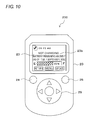
- Figs. 9 and 10 each show a display example of the display section 23 in Step S35.
- Fig. 9 is a display example of the case of the battery 30 being under charging.
- information 23a is displayed on the screen of the display section 23, the information 23a indicating that the battery 300 is under charging, time before completion of charging is 25 minutes, a remaining amount (charged amount) of the battery 300 is 65%, and the like.
- the battery remaining amount is herein displayed using both a bar graph and a numeral value, it may be displayed using either one of them.
- E at the left end of the bar graph represents the remaining amount being 0% (Empty)
- F at the right end thereof represents the remaining amount being 100% (Full).
- a current time is displayed at the top of the screen of the display section 23, and operation buttons are displayed at the bottom of the screen.
- Fig. 10 is a display example of the case of the battery 30 being not under charging.
- information 23b is displayed on the screen of the display section 23, the information 23b indicating that the battery 30 is not under charging, a battery remaining amount on a date shown in the figure is 65%, and the like.
- Step S33 when no reply is made from the in-vehicle device 100 (Step S33: NO), the process is advanced to Step S36.
- no reply there is for example considered a case where the portable device 200 is located inside a reinforced concrete building and is thus in the state of being unable to communicate with the in-vehicle device 100 located outside.
- Step S36 it is verified, with reference to the storage section 22, whether a predetermined period has not elapsed from past receipt of charge information from the in-vehicle device 100. Such a step is taken because, if a long period has lapsed from the point of receipt of charge information, the charge information is too old to be useful, and calculating a predicted value of charge information based upon this information lowers prediction accuracy, which is not preferable.
- Step S36 when a predetermined period has not elapsed (Step S36: YES), the process is advanced to Step S37, and it is checked whether or not a battery remaining amount received in the past is stored in the storage section 22. Such a step is taken because, information on a past battery remaining amount is required in calculating a predicted remaining amount of the battery and predicted time before completion of charging, and without this information, the prediction is virtually impossible.
- Steps 36 and S37 may be reversed. Further, when the determination in Step S33 is "NO", Steps S36 and S37 may be omitted, and advanced directly to Step S38. Moreover, only one of Steps S36 and S37 may be omitted.
- Step S38 prediction information regarding a state-of-charge of the battery 30 is calculated using charge information and charge characteristic data received in the past and stored in the storage section 22. Specifically, a remaining amount of the battery 30 and time before completion of charging are respectively calculated as predicted values based upon a battery remaining amount received at the most recent point when communication with the in-vehicle device 100 was possible, elapsed time from the most recent receipt (counted with the clock 26), and the charge characteristic data.
- Step S39 the predicted remaining amount and predicted time as thus calculated are displayed in the display section 23.
- Fig. 11 shows a display example of the display section 23 in Step S39.
- information 23c indicating that the battery 30 is under charging, a battery remaining amount (85%) of the battery 30 and predicted time (10 minutes) before completion of charging.
- a message is also displayed indicating that the predicted remaining amount and predicted time are estimated values, this message may be omitted.
- prediction information regarding the state-of-charge of the battery 30 is calculated on the portable device 200 side by the use of the past (most recent) charge information and the charge characteristic data, and then displayed in the display section 23. This can facilitate the user who owns the portable device 200 to know estimations of the remaining amount of the battery 30 and the time before completion of charging. Further, since prediction information is calculated using the charge characteristics generated at the point of charging the battery 30, it is possible to obtain highly accurate prediction information with surroundings, such as an ambient temperature, of the battery 30 during charging taken into consideration.
- Step S36 when the predetermined period has elapsed from past receipt of charge information in Step S36 (Step S36: NO), the process is advanced to Step 41.
- Step S41 a past charged date (the most resent date) stored in the storage section 22 and a battery remaining amount at that point are displayed in the display section 23 as past charge information.
- Fig. 12 shows a display example of the display section 23 in Step S41.
- information 23d indicating a past charged date and a battery remaining amount (80%) at that time, along with a message indicative that communication could not be performed with the vehicle. This can at least notify the user of the latest battery remaining amount in the past even when the portable device 200 cannot receive charge information from the in-vehicle device 100.
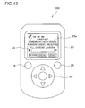
- Step S40 since prediction information cannot be calculated based upon information on the past remaining amount, a remaining amount of the battery 30 and the time before completion of charging being unknown are displayed in the display section 23.
- Fig. 13 shows a display example of the display section 23 in Step S40.
- information 23e indicating that a battery remaining amount and time before completion of charging are unknown, along with a message indicative that communication with the vehicle could not be performed.
- a current battery remaining amount and time before completion of charging are predicted using a battery remaining amount which was obtained from the in-vehicle device 100 in the past and is stored in the storage section 22, and these predicted values are displayed in the display section 23.
- a charging start time or a charged amount may be displayed in place of the predicted values.
- the portable device 200 in this case wirelessly transmits a signal, requesting charge information such as a charging start time for the battery 30 and a charged amount of the battery 30, from the transmission/reception section 21 to the in-vehicle device 100, wirelessly receives the above charge information from the in-vehicle device 100, and stores the received charge information into the storage section 22.
- the most recent charging start time or charged amount which was obtained from the in-vehicle device 100 in the past and is stored in the storage section 22, is read and displayed in the display section 23. In the display section 23, only one of the charging start time and the charged amount may be displayed, or both of them may be displayed. Also according to such an embodiment, the user can grasp estimations of a battery remaining amount and time before completion of charging.
- a door-opening/closing remote controller used in a keyless entry system for the vehicle may also serve as the portable device according to embodiments of the present invention.
- Step S6 predicted time before completion of charging was calculated (Step S6) on the in-vehicle device 100 side in the flowchart of Fig. 4 in the above embodiment, the predicted time may be calculated on the portable device 200 side.
- the charge inquiry button 25 for inquiring about a remaining amount of the battery 30 and the like is provided in the portable device 200 in the present embodiment
- the charge inquiry button may be displayed on the screen of the display section 23 and the button may be operated with the operation key 29.
- embodiments of the present invention are also applicable, for example, to a system for displaying charge information on a battery mounted in an automated guided vehicle or a robot.
Landscapes
- Engineering & Computer Science (AREA)
- Power Engineering (AREA)
- Physics & Mathematics (AREA)
- General Physics & Mathematics (AREA)
- Transportation (AREA)
- Mechanical Engineering (AREA)
- Chemical & Material Sciences (AREA)
- Signal Processing (AREA)
- Computer Networks & Wireless Communication (AREA)
- Combustion & Propulsion (AREA)
- Charge And Discharge Circuits For Batteries Or The Like (AREA)
- Electric Propulsion And Braking For Vehicles (AREA)
- Remote Monitoring And Control Of Power-Distribution Networks (AREA)
- Secondary Cells (AREA)
- Selective Calling Equipment (AREA)
- Tests Of Electric Status Of Batteries (AREA)
Applications Claiming Priority (1)
| Application Number | Priority Date | Filing Date | Title |
|---|---|---|---|
| JP2009271899A JP5641727B2 (ja) | 2009-11-30 | 2009-11-30 | 充電情報表示用携帯機および充電情報表示システム |
Publications (3)
| Publication Number | Publication Date |
|---|---|
| EP2328258A2 true EP2328258A2 (de) | 2011-06-01 |
| EP2328258A3 EP2328258A3 (de) | 2012-05-30 |
| EP2328258B1 EP2328258B1 (de) | 2016-07-27 |
Family
ID=43639116
Family Applications (1)
| Application Number | Title | Priority Date | Filing Date |
|---|---|---|---|
| EP10193113.7A Active EP2328258B1 (de) | 2009-11-30 | 2010-11-30 | Tragbare Vorrichtung zum Anzeigen der Batterieladungsinformation und Batterieladungsinformationsanzeigesystem |
Country Status (5)
| Country | Link |
|---|---|
| US (1) | US8829910B2 (de) |
| EP (1) | EP2328258B1 (de) |
| JP (1) | JP5641727B2 (de) |
| KR (1) | KR101113425B1 (de) |
| CN (1) | CN102163985B (de) |
Cited By (5)
| Publication number | Priority date | Publication date | Assignee | Title |
|---|---|---|---|---|
| FR2982560A1 (fr) * | 2011-11-15 | 2013-05-17 | Peugeot Citroen Automobiles Sa | Vehicule automobile amenage pour recevoir et charger un moyen de locomotion a motorisation electrique, transporte par ledit vehicule |
| WO2014037137A3 (de) * | 2012-09-06 | 2014-10-30 | Siemens Aktiengesellschaft | Verfahren zum laden oder entladen eines energiespeichers in einem fahrzeug, zugehöriges gerät und zugehörige station |
| EP2769870A4 (de) * | 2011-10-20 | 2016-01-27 | Lsis Co Ltd | Elektrofahrzeug und betriebsverfahren dafür |
| EP2644440A3 (de) * | 2012-03-27 | 2017-01-11 | Ford Global Technologies, LLC | Verfahren und Vorrichtung zum Management von Ladestationen für Elektrofahrzeuge |
| CN113386592A (zh) * | 2020-03-11 | 2021-09-14 | 本田技研工业株式会社 | 非接触充电系统 |
Families Citing this family (40)
| Publication number | Priority date | Publication date | Assignee | Title |
|---|---|---|---|---|
| WO2011092729A1 (ja) * | 2010-01-26 | 2011-08-04 | 三菱電機株式会社 | ナビゲーション装置、車両情報表示装置および車両情報表示システム |
| CN102439396B (zh) * | 2010-03-18 | 2013-07-10 | 丰田自动车株式会社 | 电力驱动式车辆 |
| US8509988B2 (en) * | 2010-11-16 | 2013-08-13 | Honda Motor Co., Ltd. | Cellular communication strategy |
| KR20140102188A (ko) * | 2011-10-20 | 2014-08-21 | 엘에스산전 주식회사 | 내장 자동차 통신 제어 장치 및 그 동작 방법 |
| JP5557826B2 (ja) | 2011-11-24 | 2014-07-23 | オムロンオートモーティブエレクトロニクス株式会社 | 情報通信システムおよび車両用携帯機 |
| US9214823B1 (en) * | 2011-12-20 | 2015-12-15 | Sprint Spectrum L.P. | Correlating operational states and battery usage of devices to extend battery duration |
| US8620506B2 (en) | 2011-12-21 | 2013-12-31 | Ford Global Technologies, Llc | Method and system for thermal management of a high voltage battery for a vehicle |
| US9525293B2 (en) | 2011-12-30 | 2016-12-20 | Makita Corporation | Battery charger having angled wall in battery receiving opening, and battery pack charging system and cordless power tool system including same |
| US8768419B2 (en) * | 2012-01-26 | 2014-07-01 | Verizon Patent And Licensing Inc. | Mobile battery partitioning system and method |
| JP5952065B2 (ja) * | 2012-04-06 | 2016-07-13 | トヨタホーム株式会社 | 地域内給電システム |
| KR20140003082A (ko) * | 2012-06-29 | 2014-01-09 | 엘에스산전 주식회사 | 전기 자동차용 충전기 |
| JP2014026387A (ja) * | 2012-07-25 | 2014-02-06 | Toshiba Corp | 電子機器及び消費電力表示方法 |
| WO2014049670A1 (ja) * | 2012-09-28 | 2014-04-03 | 三洋電機株式会社 | 蓄電池制御装置、蓄電池管理システムおよび蓄電システム |
| US9781496B2 (en) | 2012-10-25 | 2017-10-03 | Milwaukee Electric Tool Corporation | Worksite audio device with wireless interface |
| JP6098216B2 (ja) | 2013-02-20 | 2017-03-22 | 株式会社デンソー | タイマ備忘装置 |
| US20150029398A1 (en) * | 2013-07-24 | 2015-01-29 | Kabushiki Kaisha Toshiba | Information processing apparatus and information processing method for outputting a charging status |
| CN104466286B (zh) * | 2013-09-25 | 2017-12-26 | 联想(北京)有限公司 | 一种电量提示方法、装置及一种电子设备 |
| USD741795S1 (en) | 2013-10-25 | 2015-10-27 | Milwaukee Electric Tool Corporation | Radio charger |
| JP6045518B2 (ja) * | 2014-01-30 | 2016-12-14 | ソフトバンク株式会社 | 電池残量監視システム、電池残量監視方法、電池残量監視対象装置、電池残量監視プログラム |
| JP6375701B2 (ja) * | 2014-06-04 | 2018-08-22 | 株式会社オートネットワーク技術研究所 | 車両用通信システム、車載機、携帯機及びコンピュータプログラム |
| JP6274031B2 (ja) * | 2014-06-26 | 2018-02-07 | 株式会社オートネットワーク技術研究所 | 車両用通信システム、車載機、携帯機及びコンピュータプログラム |
| JP6528368B2 (ja) * | 2014-07-14 | 2019-06-12 | 株式会社オートネットワーク技術研究所 | 車両用通信システム、車載機、携帯機、及びコンピュータプログラム |
| JP6398425B2 (ja) * | 2014-07-25 | 2018-10-03 | 株式会社オートネットワーク技術研究所 | 車両用通信システム、車載機、携帯機及びコンピュータプログラム |
| USD773326S1 (en) * | 2015-06-18 | 2016-12-06 | Ningbo Jiangbei Run Leader Electronics Co., Ltd | Engine monitoring unit |
| USD773945S1 (en) * | 2015-07-07 | 2016-12-13 | Ningbo Jiangbei Run Leader Electronics Co., Ltd | Engine monitoring unit |
| CN106602158B (zh) * | 2015-10-14 | 2020-01-07 | 上海汽车集团股份有限公司 | 电池充电时间预测方法及装置 |
| JP6582909B2 (ja) | 2015-11-17 | 2019-10-02 | オムロン株式会社 | バッテリ予約装置およびバッテリ予約方法 |
| JP6766343B2 (ja) * | 2015-11-17 | 2020-10-14 | オムロン株式会社 | バッテリ予約装置 |
| JP6597218B2 (ja) | 2015-11-17 | 2019-10-30 | オムロン株式会社 | バッテリ予約装置およびバッテリ予約方法 |
| JP6724343B2 (ja) | 2015-11-17 | 2020-07-15 | オムロン株式会社 | 予約管理装置、予約管理システムおよび予約管理方法 |
| USD783432S1 (en) * | 2015-12-10 | 2017-04-11 | Ningbo Jiangbei Run Leader Electronics Co., Ltd | Engine monitoring unit |
| US9841466B2 (en) * | 2015-12-30 | 2017-12-12 | Thunder Power New Energy Vehicle Development Company Limited | Dynamic battery level indicator |
| JP6745715B2 (ja) * | 2016-12-20 | 2020-08-26 | キヤノン株式会社 | 情報処理装置、情報処理装置の制御方法及びプログラム |
| KR102154385B1 (ko) * | 2017-05-31 | 2020-09-09 | 주식회사 엘지화학 | 차량용 배터리 원격 관리 시스템 및 방법 |
| KR102013155B1 (ko) * | 2017-06-28 | 2019-08-22 | 주식회사 성우하이텍 | 전기자동차의 스마트키 및 그 제어 방법 |
| JP7140540B2 (ja) * | 2018-05-07 | 2022-09-21 | キヤノン株式会社 | 電子機器、および電子機器の制御方法、プログラム、記憶媒体 |
| CN112514193A (zh) * | 2018-07-31 | 2021-03-16 | 日本烟草产业株式会社 | 充电装置以及信息处理系统 |
| DE102018213643B3 (de) * | 2018-08-14 | 2019-11-28 | Audi Ag | Anzeigevorrichtung zum Anzeigen von Systemzuständen mindestens zweier Stromverbrauchergeräte, Haushaltsgerät, Möbelstück, Verfahren zum Betreiben einer Anzeigevorrichtung, Speichermedium, mobiles, portables Endgerät, und Servervorrichtung zum Betreiben im Internet |
| CN110650394B (zh) * | 2019-08-30 | 2020-08-28 | 广东思派康电子科技有限公司 | 计算机可读存储介质及无线耳机 |
| JP7358626B2 (ja) * | 2020-04-02 | 2023-10-10 | 日本たばこ産業株式会社 | 情報処理装置、情報処理方法および情報処理プログラム |
Citations (3)
| Publication number | Priority date | Publication date | Assignee | Title |
|---|---|---|---|---|
| JP2007057273A (ja) | 2005-08-22 | 2007-03-08 | Yazaki Corp | 無線子機及び携帯端末装置 |
| JP2009054302A (ja) | 2007-08-23 | 2009-03-12 | Panasonic Corp | 車両用蓄電池履歴読出し装置 |
| JP2009177509A (ja) | 2008-01-24 | 2009-08-06 | Nec Corp | 携帯通信端末用の無線通信システム、該システムで用いられる無線通信接続方法及び無線通信接続プログラム |
Family Cites Families (14)
| Publication number | Priority date | Publication date | Assignee | Title |
|---|---|---|---|---|
| JP2742722B2 (ja) * | 1990-04-24 | 1998-04-22 | 株式会社アテックス | 蓄電池の充電方法 |
| JP2996559B2 (ja) * | 1992-01-29 | 2000-01-11 | 本田技研工業株式会社 | 電気自動車の充電状況表示システム |
| JP3400034B2 (ja) * | 1993-10-12 | 2003-04-28 | 本田技研工業株式会社 | 電動車両のバッテリ残容量遠隔表示装置 |
| JPH09116977A (ja) * | 1995-10-16 | 1997-05-02 | Honda Motor Co Ltd | 表示用信号送受信方法 |
| KR100322686B1 (ko) * | 2000-04-06 | 2002-02-07 | 홍경 | 이동통신 단말기에 탑재되는 배터리의 충전완료 시간 예측방법 |
| US7362263B2 (en) * | 2003-09-04 | 2008-04-22 | Seiko Epson Corporation | Keeping accurate time for a hybrid GPS receiver and mobile phone when powered off |
| US20050052317A1 (en) * | 2003-09-04 | 2005-03-10 | Eride, Inc. | Combination navigation satellite receivers and communications devices |
| US7844370B2 (en) * | 2006-08-10 | 2010-11-30 | Gridpoint, Inc. | Scheduling and control in a power aggregation system for distributed electric resources |
| JP2008104093A (ja) * | 2006-10-20 | 2008-05-01 | Matsushita Electric Ind Co Ltd | テレビ受信装置およびビデオ録画再生装置並びにこれらを備えたビデオ録画再生システム |
| KR100843833B1 (ko) * | 2006-10-31 | 2008-07-03 | 주식회사 현대오토넷 | 차량용 배터리의 잔량 검출 기능을 가지는 내비게이션장치, 및 이를 포함하는 차량용 배터리의 방전 보호시스템과 그 동작 방법 |
| JP2008247080A (ja) * | 2007-03-29 | 2008-10-16 | Toyota Motor Corp | ハイブリッド車両の表示システム |
| US20080312782A1 (en) * | 2007-06-15 | 2008-12-18 | Gene Berdichevsky | Electric vehicle communication interface |
| US8049460B2 (en) * | 2007-07-18 | 2011-11-01 | Tesla Motors, Inc. | Voltage dividing vehicle heater system and method |
| US8509988B2 (en) * | 2010-11-16 | 2013-08-13 | Honda Motor Co., Ltd. | Cellular communication strategy |
-
2009
- 2009-11-30 JP JP2009271899A patent/JP5641727B2/ja active Active
-
2010
- 2010-11-24 US US12/954,305 patent/US8829910B2/en active Active
- 2010-11-25 KR KR1020100117939A patent/KR101113425B1/ko active IP Right Grant
- 2010-11-29 CN CN201010573535.XA patent/CN102163985B/zh active Active
- 2010-11-30 EP EP10193113.7A patent/EP2328258B1/de active Active
Patent Citations (3)
| Publication number | Priority date | Publication date | Assignee | Title |
|---|---|---|---|---|
| JP2007057273A (ja) | 2005-08-22 | 2007-03-08 | Yazaki Corp | 無線子機及び携帯端末装置 |
| JP2009054302A (ja) | 2007-08-23 | 2009-03-12 | Panasonic Corp | 車両用蓄電池履歴読出し装置 |
| JP2009177509A (ja) | 2008-01-24 | 2009-08-06 | Nec Corp | 携帯通信端末用の無線通信システム、該システムで用いられる無線通信接続方法及び無線通信接続プログラム |
Cited By (9)
| Publication number | Priority date | Publication date | Assignee | Title |
|---|---|---|---|---|
| EP2769870A4 (de) * | 2011-10-20 | 2016-01-27 | Lsis Co Ltd | Elektrofahrzeug und betriebsverfahren dafür |
| US9566873B2 (en) | 2011-10-20 | 2017-02-14 | Lsis Co., Ltd. | Electric vehicle and method of operating using an SAE standard and user terminal |
| FR2982560A1 (fr) * | 2011-11-15 | 2013-05-17 | Peugeot Citroen Automobiles Sa | Vehicule automobile amenage pour recevoir et charger un moyen de locomotion a motorisation electrique, transporte par ledit vehicule |
| WO2013072306A1 (fr) * | 2011-11-15 | 2013-05-23 | Peugeot Citroen Automobiles Sa | Vehicule automobile amenage pour recevoir et charger un moyen de locomotion a motorisation electrique, transporte par ledit vehicule |
| EP2644440A3 (de) * | 2012-03-27 | 2017-01-11 | Ford Global Technologies, LLC | Verfahren und Vorrichtung zum Management von Ladestationen für Elektrofahrzeuge |
| RU2627943C2 (ru) * | 2012-03-27 | 2017-08-14 | ФОРД ГЛОУБАЛ ТЕКНОЛОДЖИЗ, ЭлЭлСи | Способ и устройство для управления зарядными станциями для электрических транспортных средств |
| WO2014037137A3 (de) * | 2012-09-06 | 2014-10-30 | Siemens Aktiengesellschaft | Verfahren zum laden oder entladen eines energiespeichers in einem fahrzeug, zugehöriges gerät und zugehörige station |
| CN113386592A (zh) * | 2020-03-11 | 2021-09-14 | 本田技研工业株式会社 | 非接触充电系统 |
| CN113386592B (zh) * | 2020-03-11 | 2024-05-14 | 本田技研工业株式会社 | 非接触充电系统 |
Also Published As
| Publication number | Publication date |
|---|---|
| KR20110060826A (ko) | 2011-06-08 |
| EP2328258B1 (de) | 2016-07-27 |
| JP5641727B2 (ja) | 2014-12-17 |
| JP2011112617A (ja) | 2011-06-09 |
| EP2328258A3 (de) | 2012-05-30 |
| KR101113425B1 (ko) | 2012-02-29 |
| US8829910B2 (en) | 2014-09-09 |
| CN102163985A (zh) | 2011-08-24 |
| US20110128007A1 (en) | 2011-06-02 |
| CN102163985B (zh) | 2014-05-28 |
Similar Documents
| Publication | Publication Date | Title |
|---|---|---|
| EP2328258B1 (de) | Tragbare Vorrichtung zum Anzeigen der Batterieladungsinformation und Batterieladungsinformationsanzeigesystem | |
| CN108973708B (zh) | 电动车辆及其报告系统 | |
| US8390246B2 (en) | Battery charge state transmission device and external charging system | |
| US8676401B2 (en) | Door control and charge control for plug-in charge type vehicle | |
| US9283827B2 (en) | Air conditioning remote control system for a vehicle, server, and portable terminal | |
| KR102114710B1 (ko) | 차량, 차량의 제어 방법 및 충전 시스템 | |
| CN102445927B (zh) | 用于远程充电控制的远程信息处理装置和提供服务的方法 | |
| US8400107B2 (en) | Charge status display apparatus and electric power supply control apparatus | |
| US10024926B2 (en) | Method and device for monitoring at least one traction battery of a motor vehicle | |
| KR102114707B1 (ko) | 서버 및 충전 시스템 | |
| KR20130128022A (ko) | 배터리 충전량 증가 설비 정보 제공 장치 및 방법 | |
| JP6250298B2 (ja) | 二次電池寿命予測システムおよび二次電池特性評価装置 | |
| JP2013115929A (ja) | 充電補助装置 | |
| KR20100017735A (ko) | 축전지를 모니터링하기 위한 장치 | |
| CN105277897A (zh) | 电动汽车中电池包的寿命评估方法和系统 | |
| JP6282548B2 (ja) | 車載装置、連携システムおよび充電開始時刻報知方法 | |
| KR20230000479U (ko) | 차량용 배터리 모니터링 시스템 | |
| JP2021189640A (ja) | 情報処理装置、情報処理方法、およびプログラム | |
| JP7420596B2 (ja) | 充電システム | |
| JP2018126003A (ja) | 車両の充電制御装置 | |
| CN112051433B (zh) | 开路电压测量方法、开路电压测量装置以及记录介质 | |
| KR20230008511A (ko) | 차량용 배터리 모니터링 시스템 | |
| JP2022159706A (ja) | 充電制御方法及び充電制御装置 | |
| CN113442776A (zh) | 控制装置 | |
| JP2019161762A (ja) | 車両 |
Legal Events
| Date | Code | Title | Description |
|---|---|---|---|
| PUAI | Public reference made under article 153(3) epc to a published international application that has entered the european phase |
Free format text: ORIGINAL CODE: 0009012 |
|
| AK | Designated contracting states |
Kind code of ref document: A2 Designated state(s): AL AT BE BG CH CY CZ DE DK EE ES FI FR GB GR HR HU IE IS IT LI LT LU LV MC MK MT NL NO PL PT RO RS SE SI SK SM TR |
|
| AX | Request for extension of the european patent |
Extension state: BA ME |
|
| PUAL | Search report despatched |
Free format text: ORIGINAL CODE: 0009013 |
|
| RIC1 | Information provided on ipc code assigned before grant |
Ipc: H02J 7/02 20060101AFI20120329BHEP Ipc: B60L 11/18 20060101ALN20120329BHEP Ipc: G01R 31/36 20060101ALI20120329BHEP |
|
| AK | Designated contracting states |
Kind code of ref document: A3 Designated state(s): AL AT BE BG CH CY CZ DE DK EE ES FI FR GB GR HR HU IE IS IT LI LT LU LV MC MK MT NL NO PL PT RO RS SE SI SK SM TR |
|
| AX | Request for extension of the european patent |
Extension state: BA ME |
|
| 17P | Request for examination filed |
Effective date: 20121107 |
|
| GRAP | Despatch of communication of intention to grant a patent |
Free format text: ORIGINAL CODE: EPIDOSNIGR1 |
|
| RIC1 | Information provided on ipc code assigned before grant |
Ipc: H02J 7/02 20060101AFI20160202BHEP Ipc: G01R 31/00 20060101ALN20160202BHEP Ipc: B60L 11/18 20060101ALN20160202BHEP Ipc: H02J 7/00 20060101ALN20160202BHEP Ipc: G01R 31/36 20060101ALI20160202BHEP |
|
| INTG | Intention to grant announced |
Effective date: 20160304 |
|
| RIN1 | Information on inventor provided before grant (corrected) |
Inventor name: NISHIDAI, TETSUO Inventor name: TSUJIKO, YOSHIRO Inventor name: KAWASHIMA, HIDEMITSU |
|
| GRAS | Grant fee paid |
Free format text: ORIGINAL CODE: EPIDOSNIGR3 |
|
| GRAA | (expected) grant |
Free format text: ORIGINAL CODE: 0009210 |
|
| AK | Designated contracting states |
Kind code of ref document: B1 Designated state(s): AL AT BE BG CH CY CZ DE DK EE ES FI FR GB GR HR HU IE IS IT LI LT LU LV MC MK MT NL NO PL PT RO RS SE SI SK SM TR |
|
| REG | Reference to a national code |
Ref country code: GB Ref legal event code: FG4D |
|
| REG | Reference to a national code |
Ref country code: CH Ref legal event code: EP |
|
| REG | Reference to a national code |
Ref country code: AT Ref legal event code: REF Ref document number: 816497 Country of ref document: AT Kind code of ref document: T Effective date: 20160815 |
|
| REG | Reference to a national code |
Ref country code: IE Ref legal event code: FG4D |
|
| REG | Reference to a national code |
Ref country code: DE Ref legal event code: R096 Ref document number: 602010035000 Country of ref document: DE |
|
| REG | Reference to a national code |
Ref country code: LT Ref legal event code: MG4D |
|
| REG | Reference to a national code |
Ref country code: NL Ref legal event code: MP Effective date: 20160727 |
|
| REG | Reference to a national code |
Ref country code: AT Ref legal event code: MK05 Ref document number: 816497 Country of ref document: AT Kind code of ref document: T Effective date: 20160727 |
|
| PG25 | Lapsed in a contracting state [announced via postgrant information from national office to epo] |
Ref country code: HR Free format text: LAPSE BECAUSE OF FAILURE TO SUBMIT A TRANSLATION OF THE DESCRIPTION OR TO PAY THE FEE WITHIN THE PRESCRIBED TIME-LIMIT Effective date: 20160727 Ref country code: LT Free format text: LAPSE BECAUSE OF FAILURE TO SUBMIT A TRANSLATION OF THE DESCRIPTION OR TO PAY THE FEE WITHIN THE PRESCRIBED TIME-LIMIT Effective date: 20160727 Ref country code: FI Free format text: LAPSE BECAUSE OF FAILURE TO SUBMIT A TRANSLATION OF THE DESCRIPTION OR TO PAY THE FEE WITHIN THE PRESCRIBED TIME-LIMIT Effective date: 20160727 Ref country code: IT Free format text: LAPSE BECAUSE OF FAILURE TO SUBMIT A TRANSLATION OF THE DESCRIPTION OR TO PAY THE FEE WITHIN THE PRESCRIBED TIME-LIMIT Effective date: 20160727 Ref country code: IS Free format text: LAPSE BECAUSE OF FAILURE TO SUBMIT A TRANSLATION OF THE DESCRIPTION OR TO PAY THE FEE WITHIN THE PRESCRIBED TIME-LIMIT Effective date: 20161127 Ref country code: RS Free format text: LAPSE BECAUSE OF FAILURE TO SUBMIT A TRANSLATION OF THE DESCRIPTION OR TO PAY THE FEE WITHIN THE PRESCRIBED TIME-LIMIT Effective date: 20160727 Ref country code: NL Free format text: LAPSE BECAUSE OF FAILURE TO SUBMIT A TRANSLATION OF THE DESCRIPTION OR TO PAY THE FEE WITHIN THE PRESCRIBED TIME-LIMIT Effective date: 20160727 Ref country code: NO Free format text: LAPSE BECAUSE OF FAILURE TO SUBMIT A TRANSLATION OF THE DESCRIPTION OR TO PAY THE FEE WITHIN THE PRESCRIBED TIME-LIMIT Effective date: 20161027 |
|
| PG25 | Lapsed in a contracting state [announced via postgrant information from national office to epo] |
Ref country code: PT Free format text: LAPSE BECAUSE OF FAILURE TO SUBMIT A TRANSLATION OF THE DESCRIPTION OR TO PAY THE FEE WITHIN THE PRESCRIBED TIME-LIMIT Effective date: 20161128 Ref country code: LV Free format text: LAPSE BECAUSE OF FAILURE TO SUBMIT A TRANSLATION OF THE DESCRIPTION OR TO PAY THE FEE WITHIN THE PRESCRIBED TIME-LIMIT Effective date: 20160727 Ref country code: PL Free format text: LAPSE BECAUSE OF FAILURE TO SUBMIT A TRANSLATION OF THE DESCRIPTION OR TO PAY THE FEE WITHIN THE PRESCRIBED TIME-LIMIT Effective date: 20160727 Ref country code: SE Free format text: LAPSE BECAUSE OF FAILURE TO SUBMIT A TRANSLATION OF THE DESCRIPTION OR TO PAY THE FEE WITHIN THE PRESCRIBED TIME-LIMIT Effective date: 20160727 Ref country code: ES Free format text: LAPSE BECAUSE OF FAILURE TO SUBMIT A TRANSLATION OF THE DESCRIPTION OR TO PAY THE FEE WITHIN THE PRESCRIBED TIME-LIMIT Effective date: 20160727 Ref country code: AT Free format text: LAPSE BECAUSE OF FAILURE TO SUBMIT A TRANSLATION OF THE DESCRIPTION OR TO PAY THE FEE WITHIN THE PRESCRIBED TIME-LIMIT Effective date: 20160727 Ref country code: GR Free format text: LAPSE BECAUSE OF FAILURE TO SUBMIT A TRANSLATION OF THE DESCRIPTION OR TO PAY THE FEE WITHIN THE PRESCRIBED TIME-LIMIT Effective date: 20161028 Ref country code: BE Free format text: LAPSE BECAUSE OF NON-PAYMENT OF DUE FEES Effective date: 20160727 |
|
| PG25 | Lapsed in a contracting state [announced via postgrant information from national office to epo] |
Ref country code: EE Free format text: LAPSE BECAUSE OF FAILURE TO SUBMIT A TRANSLATION OF THE DESCRIPTION OR TO PAY THE FEE WITHIN THE PRESCRIBED TIME-LIMIT Effective date: 20160727 Ref country code: RO Free format text: LAPSE BECAUSE OF FAILURE TO SUBMIT A TRANSLATION OF THE DESCRIPTION OR TO PAY THE FEE WITHIN THE PRESCRIBED TIME-LIMIT Effective date: 20160727 |
|
| REG | Reference to a national code |
Ref country code: DE Ref legal event code: R097 Ref document number: 602010035000 Country of ref document: DE |
|
| PG25 | Lapsed in a contracting state [announced via postgrant information from national office to epo] |
Ref country code: BG Free format text: LAPSE BECAUSE OF FAILURE TO SUBMIT A TRANSLATION OF THE DESCRIPTION OR TO PAY THE FEE WITHIN THE PRESCRIBED TIME-LIMIT Effective date: 20161027 Ref country code: SK Free format text: LAPSE BECAUSE OF FAILURE TO SUBMIT A TRANSLATION OF THE DESCRIPTION OR TO PAY THE FEE WITHIN THE PRESCRIBED TIME-LIMIT Effective date: 20160727 Ref country code: SM Free format text: LAPSE BECAUSE OF FAILURE TO SUBMIT A TRANSLATION OF THE DESCRIPTION OR TO PAY THE FEE WITHIN THE PRESCRIBED TIME-LIMIT Effective date: 20160727 Ref country code: DK Free format text: LAPSE BECAUSE OF FAILURE TO SUBMIT A TRANSLATION OF THE DESCRIPTION OR TO PAY THE FEE WITHIN THE PRESCRIBED TIME-LIMIT Effective date: 20160727 Ref country code: CZ Free format text: LAPSE BECAUSE OF FAILURE TO SUBMIT A TRANSLATION OF THE DESCRIPTION OR TO PAY THE FEE WITHIN THE PRESCRIBED TIME-LIMIT Effective date: 20160727 |
|
| PLBE | No opposition filed within time limit |
Free format text: ORIGINAL CODE: 0009261 |
|
| STAA | Information on the status of an ep patent application or granted ep patent |
Free format text: STATUS: NO OPPOSITION FILED WITHIN TIME LIMIT |
|
| REG | Reference to a national code |
Ref country code: CH Ref legal event code: PL |
|
| 26N | No opposition filed |
Effective date: 20170502 |
|
| GBPC | Gb: european patent ceased through non-payment of renewal fee |
Effective date: 20161130 |
|
| PG25 | Lapsed in a contracting state [announced via postgrant information from national office to epo] |
Ref country code: LI Free format text: LAPSE BECAUSE OF NON-PAYMENT OF DUE FEES Effective date: 20161130 Ref country code: CH Free format text: LAPSE BECAUSE OF NON-PAYMENT OF DUE FEES Effective date: 20161130 |
|
| REG | Reference to a national code |
Ref country code: IE Ref legal event code: MM4A |
|
| REG | Reference to a national code |
Ref country code: FR Ref legal event code: ST Effective date: 20170731 |
|
| PG25 | Lapsed in a contracting state [announced via postgrant information from national office to epo] |
Ref country code: SI Free format text: LAPSE BECAUSE OF FAILURE TO SUBMIT A TRANSLATION OF THE DESCRIPTION OR TO PAY THE FEE WITHIN THE PRESCRIBED TIME-LIMIT Effective date: 20160727 |
|
| PG25 | Lapsed in a contracting state [announced via postgrant information from national office to epo] |
Ref country code: LU Free format text: LAPSE BECAUSE OF NON-PAYMENT OF DUE FEES Effective date: 20161130 |
|
| PG25 | Lapsed in a contracting state [announced via postgrant information from national office to epo] |
Ref country code: FR Free format text: LAPSE BECAUSE OF NON-PAYMENT OF DUE FEES Effective date: 20161130 |
|
| PG25 | Lapsed in a contracting state [announced via postgrant information from national office to epo] |
Ref country code: GB Free format text: LAPSE BECAUSE OF NON-PAYMENT OF DUE FEES Effective date: 20161130 Ref country code: IE Free format text: LAPSE BECAUSE OF NON-PAYMENT OF DUE FEES Effective date: 20161130 |
|
| PG25 | Lapsed in a contracting state [announced via postgrant information from national office to epo] |
Ref country code: HU Free format text: LAPSE BECAUSE OF FAILURE TO SUBMIT A TRANSLATION OF THE DESCRIPTION OR TO PAY THE FEE WITHIN THE PRESCRIBED TIME-LIMIT; INVALID AB INITIO Effective date: 20101130 Ref country code: CY Free format text: LAPSE BECAUSE OF FAILURE TO SUBMIT A TRANSLATION OF THE DESCRIPTION OR TO PAY THE FEE WITHIN THE PRESCRIBED TIME-LIMIT Effective date: 20160727 |
|
| PG25 | Lapsed in a contracting state [announced via postgrant information from national office to epo] |
Ref country code: TR Free format text: LAPSE BECAUSE OF FAILURE TO SUBMIT A TRANSLATION OF THE DESCRIPTION OR TO PAY THE FEE WITHIN THE PRESCRIBED TIME-LIMIT Effective date: 20160727 Ref country code: MC Free format text: LAPSE BECAUSE OF FAILURE TO SUBMIT A TRANSLATION OF THE DESCRIPTION OR TO PAY THE FEE WITHIN THE PRESCRIBED TIME-LIMIT Effective date: 20160727 Ref country code: MK Free format text: LAPSE BECAUSE OF FAILURE TO SUBMIT A TRANSLATION OF THE DESCRIPTION OR TO PAY THE FEE WITHIN THE PRESCRIBED TIME-LIMIT Effective date: 20160727 |
|
| PG25 | Lapsed in a contracting state [announced via postgrant information from national office to epo] |
Ref country code: MT Free format text: LAPSE BECAUSE OF NON-PAYMENT OF DUE FEES Effective date: 20161130 |
|
| PG25 | Lapsed in a contracting state [announced via postgrant information from national office to epo] |
Ref country code: AL Free format text: LAPSE BECAUSE OF FAILURE TO SUBMIT A TRANSLATION OF THE DESCRIPTION OR TO PAY THE FEE WITHIN THE PRESCRIBED TIME-LIMIT Effective date: 20160727 |
|
| REG | Reference to a national code |
Ref country code: DE Ref legal event code: R082 Ref document number: 602010035000 Country of ref document: DE Representative=s name: DOMPATENT VON KREISLER SELTING WERNER - PARTNE, DE |
|
| PGFP | Annual fee paid to national office [announced via postgrant information from national office to epo] |
Ref country code: DE Payment date: 20221004 Year of fee payment: 13 |