EP2325035A1 - Grillsteuerungsmechanismus für Fahrzeug - Google Patents
Grillsteuerungsmechanismus für Fahrzeug Download PDFInfo
- Publication number
- EP2325035A1 EP2325035A1 EP10190858A EP10190858A EP2325035A1 EP 2325035 A1 EP2325035 A1 EP 2325035A1 EP 10190858 A EP10190858 A EP 10190858A EP 10190858 A EP10190858 A EP 10190858A EP 2325035 A1 EP2325035 A1 EP 2325035A1
- Authority
- EP
- European Patent Office
- Prior art keywords
- movable member
- control means
- current value
- case
- lock current
- Prior art date
- Legal status (The legal status is an assumption and is not a legal conclusion. Google has not performed a legal analysis and makes no representation as to the accuracy of the status listed.)
- Granted
Links
- 230000002159 abnormal effect Effects 0.000 claims abstract description 24
- 239000012080 ambient air Substances 0.000 claims description 9
- 230000002401 inhibitory effect Effects 0.000 claims description 4
- 230000005856 abnormality Effects 0.000 description 13
- 239000002826 coolant Substances 0.000 description 11
- 239000003570 air Substances 0.000 description 10
- 238000001514 detection method Methods 0.000 description 9
- 238000001816 cooling Methods 0.000 description 5
- 238000010586 diagram Methods 0.000 description 5
- 230000007257 malfunction Effects 0.000 description 5
- 230000001965 increasing effect Effects 0.000 description 4
- 238000000034 method Methods 0.000 description 4
- 238000004519 manufacturing process Methods 0.000 description 3
- 230000007613 environmental effect Effects 0.000 description 2
- 230000005540 biological transmission Effects 0.000 description 1
- 238000006073 displacement reaction Methods 0.000 description 1
- 230000000694 effects Effects 0.000 description 1
- 230000002708 enhancing effect Effects 0.000 description 1
Images


Classifications
-
- B—PERFORMING OPERATIONS; TRANSPORTING
- B60—VEHICLES IN GENERAL
- B60K—ARRANGEMENT OR MOUNTING OF PROPULSION UNITS OR OF TRANSMISSIONS IN VEHICLES; ARRANGEMENT OR MOUNTING OF PLURAL DIVERSE PRIME-MOVERS IN VEHICLES; AUXILIARY DRIVES FOR VEHICLES; INSTRUMENTATION OR DASHBOARDS FOR VEHICLES; ARRANGEMENTS IN CONNECTION WITH COOLING, AIR INTAKE, GAS EXHAUST OR FUEL SUPPLY OF PROPULSION UNITS IN VEHICLES
- B60K11/00—Arrangement in connection with cooling of propulsion units
- B60K11/08—Air inlets for cooling; Shutters or blinds therefor
- B60K11/085—Air inlets for cooling; Shutters or blinds therefor with adjustable shutters or blinds
-
- Y—GENERAL TAGGING OF NEW TECHNOLOGICAL DEVELOPMENTS; GENERAL TAGGING OF CROSS-SECTIONAL TECHNOLOGIES SPANNING OVER SEVERAL SECTIONS OF THE IPC; TECHNICAL SUBJECTS COVERED BY FORMER USPC CROSS-REFERENCE ART COLLECTIONS [XRACs] AND DIGESTS
- Y02—TECHNOLOGIES OR APPLICATIONS FOR MITIGATION OR ADAPTATION AGAINST CLIMATE CHANGE
- Y02T—CLIMATE CHANGE MITIGATION TECHNOLOGIES RELATED TO TRANSPORTATION
- Y02T10/00—Road transport of goods or passengers
- Y02T10/80—Technologies aiming to reduce greenhouse gasses emissions common to all road transportation technologies
- Y02T10/88—Optimized components or subsystems, e.g. lighting, actively controlled glasses
Definitions
- This disclosure generally relates to a grille control mechanism for a vehicle for controlling an opening and closing operation of a movable member, which is configured so as to be switchable between an opening position for allowing ambient air to flow into a radiator provided at the vehicle and a closing position for inhibiting or restricting the ambient air from flowing into the radiator.
- JP2008-6855A Disclosed in JP2008-6855A is an example of a known grille control mechanism for a vehicle.
- a movable member is provided between a front grille and a radiator of the vehicle, so that an aerodynamic characteristic of the vehicle, an engine temperature and the like is adjusted by adjusting inflow of air from a front portion of the vehicle to the radiator, in order to achieve a preferable driving performance of the vehicle.
- the movable member is configured as a movable fin, which is pivotable about a horizontal axis. Accordingly, the inflow of the air is adjusted by controlling an air inlet passage to be opened and closed by the movable fin so that air resistance, lift force or downforce is applied to the vehicle in order to ensure a stable driving performance of the vehicle.
- JPH5-50861A Disclosed in JPH5-50861A is another example of a known grille control mechanism for a vehicle.
- a movable member (a movable grille) is controlled to be opened and closed in response to an environmental condition (e.g. ambient temperature and the like) and an engine load condition (e.g. a temperature of an engine cooling medium and the like).
- the grille control mechanism for the vehicle disclosed in JPH5-50861A estimates an opening-closing state of the movable member, by which an appropriate cooling effect is supposed to be obtained under a certain environmental condition and the engine load condition, on the basis of plural determination conditions, which are stored within a storing means. Then, the grille control mechanism executes an opening-closing control of the movable member on the basis of the estimation result in order to adjust cooling of the engine cooling medium to be appropriate.
- Both of the grille control mechanism disclosed in JP2008-6855A and the grille control mechanism disclosed in JPH5-50861A are intended to improve the cooling of the engine cooling medium, to achieve a driving stability of the vehicle and the like by controlling the movable member to be at the opened position or the closed position on the basis of each condition. Therefore, in a case where a mechanical error or malfunction occurs at a driving mechanism of the movable member because of, for example, an object being caught in the movable member, the operation in response to the control may not property be executed.
- a user may need to take an appropriate action, such as removing the pebble, every time when the grille control mechanism determines that the error or the malfunction occurs when the easily removable object is caught in the movable member.
- a grille control mechanism for a vehicle includes a movable member, whose position is switchable between an opened position for allowing an ambient air to flow into a radiator provided at the vehicle and a closed position for inhibiting or restricting the ambient air from flowing into the radiator, an electric motor actuating the movable member, and a control means controlling an electric current to be supplied to the electric motor until detecting a lock current value in order to selectively execute one of an opening operation for moving the movable member to the opened position and a closing operation for moving the movable member to the closed position, wherein the control means executes a checking operation for returning the movable member to an initial position where the movable member is located when the one of the selectively executed opening and closing operations is started and executing once again one of the selectively executed opening operation and the closing operation in a case where a time for detecting the lock current value since one of the selectively executed opening operation and the closing operation is started exceeds a predetermined time, and the control means determines an operation state
- the control means does not immediately determine that the movable member is in the abnormal state in the case where the time (a time duration) for detecting the lock current value in the one of the selectively executed opening operation and the closing operation of the movable member exceeds the predetermined time (a predetermined time duration).
- the control means executes the checking operation for returning the movable member to the initial position once and then executing once again the one of the selectively executed opening operation and the closing operation. Then, the control means executes the abnormality determination on the basis of whether or not the time for detecting the lock current value in another opening operation or the closing operation exceeds the predetermined time.
- the abnormality determination is executed on the basis of the time (time duration) for detecting the lock current value, an additional potentiometer and the like for detecting a position of the movable member does not need to be provided at the grille control mechanism for the vehicle.
- the grille control mechanism for the vehicle having a flexibility in being mounted to various types of vehicle may be achieved while avoiding the increase in the manufacturing costs of the grille control mechanism.
- the control means does not need to memorize the time for detecting the past lock current value(s).
- a control program may be simplified. Still further, for example, in the case where an object is caught in the movable member and the movable member becomes immovable, but the movable member is returnable to a normal state, where the object is removed, by restoring the movable member to the initial position, the movable member is once returned to the initial position by the check operation. Then, in the case where the abnormality is resolved in the checking operation, the operation control becomes continuable.
- the predetermined number of times is set to two times.
- the control means may determine that the movable member is in the abnormal state before the object caught in the movable member is completely removed.
- a number of times the checking operation is executed until the control means determines the abnormal state may be increased, which may result in increasing a power consumption. Therefore, the predetermined number of times may preferably set to be two times or approximately two times. As a result, the object caught in the movable member may be surely removed in the checking operation while reducing the power consumption.
- the control means determines that the movable member is in an immovable state where the movable member is not allowed to be moved to the opened position and the closed position in a case where the control means determines that the movable member is in the abnormal state and the lock current value in the most recent checking operation is detected immediately after the one of the selectively executed opening operation and the closing operation is started, and wherein the control means determines that the movable member is in a partial range movable state where the movable member is allowed to move for some of range between the opened position and the closed position in a case where the control means determines that the movable member is in the abnormal state and the lock current value in the most recent checking operation is not detected immediately after the one of the selectively executed opening operation and the closing operation is started.
- the control means may determine whether the movable member is in the immovable state, where the movable member is not movable at all or in the partial range movable state where the movable member is allowed to move for some of range (distance) between the opened position and the closed position on the basis of the determination whether or not the lock current value in the one of the selectively executed opening operation and the closing operation in the most recent checking operation is detected immediately after the operation is started. Accordingly, because the control means executes the abnormality determination on the basis only of the time for detecting the lock current value in the one of the selectively executed opening operation and the closing operation in the most recent checking operation, the control means does not need to memorize the time for detecting the lock current value(s) in a previous checking operation(s). Therefore, the control program may be simplified. Additionally, the "most recent checking operation" includes a first (and the last) checking operation in a case where the checking operation is executed only once.
- control means stops the one of the selectively executed opening operation and the closing operation of the movable member in the case where the movable member is in the immovable state and the control means returns the movable member to the position where the movable member is located when the one of the selectively executed opening and closing operations is started and then, the control means stops the one of the selectively executed opening operation and the closing operation in the case where the movable member is in the partial range movable state.
- the grill control mechanism for the vehicle further includes a warning device for informing an occupant the abnormal state of the movable member.
- the warning device includes a warning lamp.
- the warning device includes a warning buzzer.
- control means stops the operation control in the case where the movable member is in the immovable state, the excessive load may be avoided from being applied to the movable member, the electric motor and the like, which occurs when the operation control is continued even if the movable member is not able to move any further. Furthermore, in the case where the control means determines that the movable member is in the partial range movable state, the movable member is returned to the initial position and then, the control means stops the operation control.
- the control means determines that the movable member is in the partial range movable state because the object is caught in the movable member, the damage may be avoided from being generated at the movable member, which may occur when the object is left being caught in the movable member.
- Fig. 1 is a cross-sectional diagram illustrating a front portion of a vehicle in a case where a movable member is at an opened position;
- Fig. 2 is a cross-sectional diagram illustrating the front portion of the vehicle in a case where the movable member is at a closed position;
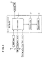
- Fig. 3 is a diagram illustrating a configuration of a grille control mechanism for the vehicle according to an embodiment
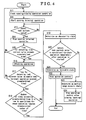
- Fig. 4 is a flowchart illustrating an abnormality determination process
- Fig. 5 is a flowchart illustrating processes of a checking operation.
- FIG. 1 Illustrated in Fig. 1 is a cross-sectional diagram of a front portion of the vehicle in a case where a movable member 21 is at an opened position. In this embodiment, plural movable members 21 are provided at the vehicle.
- FIG. 2 Illustrated in Fig. 2 is a cross-sectional diagram of the front portion of the vehicle in a case where the movable members 21 are at a closed position.
- an engine 2 and a radiator 3 for cooling a cooling medium of the engine 2 are mounted in an engine room 1.
- the movable members 21 are provided in front of the radiator 3 in a front-rear direction of the vehicle.
- the movable members 21 are controlled to be opened and closed by a control means 11 (a control device), so that air inlet from a front grille 4 is controlled to be allowed and inhibited to flow into the engine room 1.
- the front grilles 4 are provided above and below a bumper 5. More specifically, each front grille 4 includes frame portions 4a mainly forming a design of the front grille 4 and opening portions 4b for allowing the air (ambient air) to flow towards the engine room 1.
- Each of the movable members 21 includes a main movable member 21 a and a driven member 21 b. Furthermore, each of the movable members 21 is configured so that the main movable member 21 a and the driven member 21 b, which are arranged adjacent to each other, are actuated together as a unit.
- a rotating shaft 22 (in this embodiment, plural rotating shafts 22 are provided) includes a first rotating shaft 22a and a second rotating shaft 22b.
- the first rotating shafts 22a which are connected to end portions of the main movable members 21 a, respectively, and which extend in a vehicle width direction
- the second rotating shafts 22b which are connected to end portions of the driven member 21 b, respectively, and which extend in the vehicle width direction
- a force (a rotational force) generated by an electric motor 12 (see Fig. 3 )
- the force which is generated by the electric motor 12 and is transmitted through a transmission system, is also transmitted to the second rotating shafts 22b via the gear, so that the driven members 21 b are simultaneously rotated together with the corresponding main movable members 21 a.
- the air introduced from the front grilles 4 is allowed to flow into the engine room 1 and facilitates the cooling of the cooling medium, which flows inside of the radiator 3.
- the air introduced from the front grilles 4 does not inflow into the engine room 1. Therefore, in this case, air resistance, a lift force and the like acting on the vehicle becomes smaller.
- the air blocked by the movable members 21 from entering into the engine room 1 flows under a floor of the vehicle and generates a downforce on the vehicle. Therefore, in the case where the movable members 21 are controlled to be at the closed position, a driving stability of the vehicle may be enhanced.
- Illustrated in Fig. 3 is a configuration of the grille control mechanism for the vehicle.
- the control means 11 reads out detection values from a speed sensor 13, an ambient temperature sensor 14 and a cooling medium temperature sensor 15. Then, the control means 19 determines whether or not an opening operation condition for controlling the movable members 21 to be at the opened position is satisfied on the basis of the detection values and determines whether or not a closing operation condition for controlling the movable members 21 to be at the closed position is satisfied on the basis of the detection values. For example, in a case where a speed, which is detected by the speed sensor 13, is determined to be great, the control means 11 executes the closing operation (i.e. controlling the movable members 21 to be at the closed position) in order to ensure and enhance the driving stability of the vehicle.
- the closing operation i.e. controlling the movable members 21 to be at the closed position
- the control means 11 executes the opening operation (i.e. controlling the movable members 21 to be at the opened position) in order to effectively cool down the cooling medium.
- the control means 11 executes the determination of the opening operation condition and the closing operation condition on the basis of the detection values from the speed sensor 13, the ambient temperature sensor 14 and the cooling medium temperature sensor 15.
- a determination factor for the opening operation condition and the closing operation condition is not limited to the above-mentioned detection values, For example, a detection value from other sensor may be used as a determination factor.
- An electric current is supplied to the electric motor 12 in the case where the control means 11 determines that the opening operation or the closing operation needs to be executed, accordingly, the movable members 21 are driven.
- control means 11 monitors the electric current supplied to the electric motor 12, so that the control means 11 controls the electric current supplied to the electric motor 12 to be stopped in a case where the control means 11 detects a lock current value in order to stop the actuation of the movable members 21.
- the lock current value is detected when the movable members 21 reach a mechanical end portion, beyond which the movable members 21 are not movable.
- the control means 11 appropriately reads out the detection values from the speed sensor 13, the ambient temperature sensor 14 and the cooling medium temperature sensor 15 while the vehicle is moving. Then, the control means 11 determines whether the opening operation condition for controlling the movable members 21 to be at the opened position or the closing operation condition for controlling the movable members 21 to be at the closed position is satisfied on the basis of the detection values (step S11). The control means 11 controls the electric current to be supplied to the electric motor 12 in response to the determination result and starts the opening operation or the closing operation (step S12).
- step S13 A detailed explanation of steps following step S13 will be given on the basis of a case where the opening operation condition is satisfied in step S11 and the opening operation is started in step S12 in order to facilitate the explanation of the abnormality determination executed by the control means 11. The same is applied to a detailed explanation of a checking operation illustrated in a flowchart of Fig. 5 . Additionally, the abnormality determination and the checking operation executed when the closing operation condition is satisfied in step S 11 will be explained by replacing "opening" operation by the "closing" operation as indicated within brackets in Figs. 4 and 5 .
- the control means 11 monitors the current value applied to the electric motor 12 and checks whether or not the current value reaches the lock current value (step S13). In a case where the control means 11 does not detect the lock current value (No in step S13), the control means 11 controls the electric current to be continuously supplied to the electric motor 12 until the current value applied thereto reaches the lock current value. On the other hand, in a case where the control means 11 detects the lock current value (Yes in step S13), the control means 11 controls the electric current to be stopped being supplied to the electric motor 12 in order to stop the opening operation of the movable members 21 (step S14). Then, the control means 11 determines whether or not a time (a time duration) required for the lock current value to be detected exceeds a predetermined time (a predetermined time duration) (step S15).
- a time a time duration
- step S15 In a case where the time for detecting the lock current value does not exceed the predetermined time (No in step S15), in other words, in a case where the control means 11 determines that a displacement of the movable members 21 to the opened position is completed without any problems, the control means 11 appropriately checks the operation condition and continues a normal opening/closing control (steps S11 to S15). On the other hand, in a case where the time for detecting the lock current value exceeds the predetermined time (Yes in step S15), it may be considered that some error, abnormality, a malfunction or the like occurs in a process of displacing the movable members 21 to the opened position and the movable members 21 stop moving before reaching the opened position. Hence, the control means 11 executes the checking operation for determining whether or not the operation state of the movable members 21 is in an abnormal state (step S16).
- the checking operation executed by the control means 11 will be described in detail with reference to the flowchart illustrated in Fig. 5 .
- the control means 11 reversely actuates the electric motor 12 (in order to reversely rotate the electric motor 12) in order to execute an operation of restoring the movable members 21 to an initial position, in other words, start the closing operation in this case (step S31).
- the aforementioned closing operation is referred to as a "close-to-check operation”.
- the control means 11 continuously executes the close-to-check operation until the control means 11 detects the lock current value.
- step S32 When the control means 11 detects the lock current value (Yes in step S32), the control means 11 stops the close-to-check operation (step S33) and reversely rotates the electric motor 12 in order to start the opening operation (step S34).
- the aforementioned opening operation is referred to as an "open-to-check operation".
- the control means 11 continuously executes the open-to-check operation until the control means 11 detects the lock current value. Then, when the control means 11 detects the lock current value (Yes in step S35), the control means 11 stops the open-to-check operation (step S36) and the check operation is terminated.
- the control means 11 determines whether or not the time for detecting the lock current value in the open-to-check operation exceeds the predetermined time (step S17). Accordingly, because the abnormality of the operation state of the movable members 21 is determined on the basis only of the time (the time duration) for detecting the lock current value in the immediate open-to-check operation, instead of based on a time (a time duration) for detecting the lock current value in the close-to-check operation, the control means 11 does not need to memorize the time for detecting the lock current value. As a result, a control program may be simplified.
- step S17 In a case where the time for detecting the lock current value in the open-to-check operation does not exceed the predetermined time (No in step S17), the control means 11 continuously executes the normal opening/closing operation while appropriately checking the operation condition (steps S11 to S15). On the other hand, in a case where the time for detecting the lock current value in the open-to-check operation exceeds the predetermined time (Yes in step S17), the control means 11 determines whether or not a number of times when the time for detecting the lock current value exceeds the predetermined time in a row reaches a predetermined number of times (step S18).
- the predetermined number of times is preliminarily set. Any desired number of times including one (1, once) may be set as the predetermined number of times. However, in a case where a great number of times is set as the predetermined number of times, a number of times of the checking operation until the control means 11 determines the abnormal state may be increased, which may result in increasing power consumption. On the other hand, in a case where one (1, once) is set as the predetermined number of times, the control means 11 may determine that the movable members 21 are in the abnormal state before the object caught in the movable members 21 is completely removed. Therefore, the predetermined number of times may preferably set as two or approximately two.
- step S18 In a case where the number of times when the time for detecting the lock current value in the open-to-check operation exceeds the predetermined time is less than the predetermined number of times (No in step S18), the control means 11 once again executes the checking operation (step S16). On the other hand, in a case where the number of times when the time for detecting the lock current value in the open-to-check operation exceeds the predetermined time in the row reaches the predetermined number of times (Yes in step S18), the control means 11 determines that the operation state of the movable members 21 are in the abnormal state (step S19).
- control means 11 may be modified so as to determine the abnormal state of the movable members 21 in a case where a total number of times when the time for detecting the lock current value in the open-to-check operation exceeds the predetermined time reaches the predetermined number of times, instead of determining the abnormal state of the movable members 21 in the case where the number of times when the time for detecting the lock current value in the open-to-check operation exceeds the predetermined time in the row reaches the predetermined number of times. Additionally, in the case where the control means 11 determines that the movable members 21 are in the abnormal state, the control means 11 activates a warning lamp 50, a warning buzzer or the like (i.e. a warning device) in order to inform an occupant that the abnormality occurs.
- a warning lamp 50 i.e. a warning device
- control means 11 determines that the movable members 21 are in the abnormal state
- the control means 11 checks whether or not the lock current value in the open-to-check operation is detected immediately after the operation is started (step S20).
- the detection of the lock current value immediately after the operation is started indicates that the lock current value is instantaneously detected when the electric current is supplied to the electric motor 12.
- the control means 11 determines that the movable members 21 are not returned to the closed position by the close-to-check operation, in other words, the movable members 21 are in an immovable state where the movable members 21 are not bale to be moved to the opened position and to the closed position (step S21). In this case, the control means 11 stops the operation control in order to avoid an excessive load to be applied to the movable members 21, the electric motor 12 and the like, which occurs when the movable members 21 are controlled to be forcedly moved while the movable members 21 are in the immovable state (step S22).
- the control means 11 determines that the movable members 21 are returned to the closed position by the close-to-check operation, in other words, the movable members 21 are in a partial range movable state where the movable members 21 are allowed to move in some distance between the opened position and the closed position (i.e. some of a distance between the opened position and the closed position) (step S23).
- control means 11 executes the operation of restoring the movable members 21 to a position at which the movable members 21 are located when the operation is started, in other words, the control means 11 executes the opening operation and then stops the operation control in order to avoid a damage generated to the movable members 21 when the object is left being caught in the movable members 21 while the movable members 21 are in the abnormal state where the object is caught therein (step S24).
- the control means 11 determines whether or not the lock current value is detected (step S20) immediately after the operation is started on the basis of the time for detecting the lock current value in the open-to-check operation (step S34, see Fig. 5 ). Accordingly, because the control means 11 does not need to memorize the time (the time duration) required for the lock current value to be detected in the close-to-check operation executed in step S31 (see Fig. 5 ), the control program may be simplified. Alternatively, a time (a time duration) for detecting the lock current value in the close-to-check operation may be used for determining whether or not the lock current value is detected immediately after the operation is started in step S20.
- the control means 11 may be modified so as to determine that the operation state of the movable members 21 is the abnormal state in a case where a predetermined time has elapsed without detecting the lock current value after the operation is started in step S12.
- each movable member 21 includes the main movable member 21 a and the driven member 21 b, as illustrated in Figs. 1 and 2 .
- each of the movable members 21 does not need to include the main movable member 21a and the driven member 21 b as different components, but all of the movable member 21 may be driven independently of each other.
- the rotating shaft 22 of the movable member 21 may be provided at other portion of the movable member 21 other than the end portion thereof.
- the grille control mechanism for the vehicle for controlling the opening/closing operation of the movable members 21, which are configured so as to be switchable between the opened position for allowing the ambient air to flow into the radiator 3 and the closed position for inhibiting or restricting the ambient air from flowing into the radiator 3, may be achieved.
- a grille control mechanism for a vehicle includes a movable member (21) being switchable between opened and closed positions, an electric motor (12) actuating the movable member, and a control means (11) controlling a supply of electric current until detecting a lock current value to execute an opening operation or a closing operation, wherein the control means executes a checking operation for returning the movable member to an initial position and executing once again the opening or closing operation in a case where a detecting time of the lock current value since the opening or closing operation is started exceeds a predetermined time, and the control means determines that the movable member is in an abnormal state in a case where a detecting time of the lock current value after the operation is started from the initial position in the checking operation exceeds the predetermined time for a predetermined number of times.
Landscapes
- Engineering & Computer Science (AREA)
- Chemical & Material Sciences (AREA)
- Combustion & Propulsion (AREA)
- Transportation (AREA)
- Mechanical Engineering (AREA)
- Cooling, Air Intake And Gas Exhaust, And Fuel Tank Arrangements In Propulsion Units (AREA)
Applications Claiming Priority (1)
| Application Number | Priority Date | Filing Date | Title |
|---|---|---|---|
| JP2009264028A JP5424039B2 (ja) | 2009-11-19 | 2009-11-19 | 車両用グリル制御機構 |
Publications (2)
| Publication Number | Publication Date |
|---|---|
| EP2325035A1 true EP2325035A1 (de) | 2011-05-25 |
| EP2325035B1 EP2325035B1 (de) | 2011-11-09 |
Family
ID=43558040
Family Applications (1)
| Application Number | Title | Priority Date | Filing Date |
|---|---|---|---|
| EP10190858A Not-in-force EP2325035B1 (de) | 2009-11-19 | 2010-11-11 | Grillsteuerungsmechanismus für Fahrzeug |
Country Status (5)
| Country | Link |
|---|---|
| US (1) | US8571749B2 (de) |
| EP (1) | EP2325035B1 (de) |
| JP (1) | JP5424039B2 (de) |
| AT (1) | ATE532660T1 (de) |
| AU (1) | AU2010241372B2 (de) |
Cited By (11)
| Publication number | Priority date | Publication date | Assignee | Title |
|---|---|---|---|---|
| EP2371603A1 (de) * | 2010-03-25 | 2011-10-05 | Aisin Seiki Kabushiki Kaisha | Bewegliche Grillblendenvorrichtung für ein Fahrzeug |
| DE102010060253A1 (de) * | 2010-10-29 | 2012-05-03 | Brose Fahrzeugteile Gmbh & Co. Kommanditgesellschaft, Coburg | Vorrichtung zur Einstellung einer Kühlluftzuströmung |
| GB2497760A (en) * | 2011-12-20 | 2013-06-26 | Nissan Motor Mfg Uk Ltd | Air intake assembly |
| NL2008990C2 (nl) * | 2012-06-12 | 2013-12-16 | Mci Mirror Controls Int Nl Bv | Verstelinrichting en werkwijze voor het verstellen van afsluitelementen. |
| EP2674314A2 (de) | 2012-06-13 | 2013-12-18 | Decoma (Germany) GmbH | Übertragungselement für ein Kraftfahrzeug |
| EP2674315A2 (de) | 2012-06-13 | 2013-12-18 | Decoma (Germany) GmbH | Lastbegrenzer |
| EP2674316A2 (de) | 2012-06-13 | 2013-12-18 | Decoma (Germany) GmbH | Steuerbarer Lufteinlass für ein Kraftfahrzeug |
| DE102012214474A1 (de) | 2012-08-14 | 2014-05-15 | Decoma (Germany) Gmbh | Steuerbarer Lufteinlass für ein Kraftfahrzeug |
| US9869283B2 (en) | 2010-11-15 | 2018-01-16 | Mci (Mirror Controls International) Netherlands B.V. | Adjustment device for air inlet, method for adjusting an air inlet with an adjustment device, motor vehicle provided with an air inlet having an adjustment device |
| US9975420B2 (en) | 2011-07-21 | 2018-05-22 | Mci (Mirror Controls International) Netherlands B.V. | Adjustment device with drive unit; air inlet with such an adjustment device; motor vehicle with such an air inlet |
| US10272768B2 (en) | 2012-07-02 | 2019-04-30 | Mci (Mirror Controls International Netherlands B.V. | Adjustment system, primary adjustment unit and secondary adjustment unit, air intake, motor vehicle |
Families Citing this family (25)
| Publication number | Priority date | Publication date | Assignee | Title |
|---|---|---|---|---|
| JP2012121516A (ja) * | 2010-12-10 | 2012-06-28 | Aisin Seiki Co Ltd | グリルシャッター開閉制御装置 |
| JP5358603B2 (ja) * | 2011-03-18 | 2013-12-04 | トヨタ自動車株式会社 | 車両用開閉作動機構制御装置 |
| JP5919720B2 (ja) * | 2011-10-17 | 2016-05-18 | アイシン精機株式会社 | グリルシャッタ装置 |
| JP5811858B2 (ja) | 2012-01-17 | 2015-11-11 | アイシン精機株式会社 | グリルシャッタ装置 |
| JP5853801B2 (ja) * | 2012-03-22 | 2016-02-09 | アイシン精機株式会社 | グリルシャッタ装置 |
| US20130338870A1 (en) * | 2012-06-15 | 2013-12-19 | Chrysler Group Llc | System and method for performing diagnostics of an active grille shutter system |
| JP2015021995A (ja) * | 2013-07-16 | 2015-02-02 | 株式会社有沢製作所 | 眼鏡 |
| JP2015093665A (ja) * | 2013-11-14 | 2015-05-18 | アイシン精機株式会社 | グリルシャッタ装置 |
| KR101550616B1 (ko) * | 2013-12-18 | 2015-09-08 | 현대자동차 주식회사 | 차량용 냉각 시스템 및 제어 방법 |
| JP5873510B2 (ja) | 2014-01-16 | 2016-03-01 | 富士重工業株式会社 | 可変ダクトにおけるシャッタの異常報知装置 |
| JP5928497B2 (ja) | 2014-01-31 | 2016-06-01 | トヨタ自動車株式会社 | 車両 |
| CN104832268A (zh) * | 2014-06-17 | 2015-08-12 | 北汽福田汽车股份有限公司 | 用于发动机的散热装置、发动机冷却系统及方法 |
| DE102014110198A1 (de) * | 2014-07-21 | 2016-01-21 | Dr. Ing. H.C. F. Porsche Aktiengesellschaft | Bug eines Kraftfahrzeuges |
| DE102014222268A1 (de) * | 2014-10-31 | 2016-05-04 | Bayerische Motoren Werke Aktiengesellschaft | Kraftfahrzeug mit einer Frontschürze mit kanalartigen Luftleiteinrichtungen |
| KR102241456B1 (ko) * | 2014-12-30 | 2021-04-19 | 에스엘 주식회사 | 플랩 개폐 제어 장치 및 방법 |
| DE102016218391A1 (de) * | 2016-09-23 | 2018-03-29 | Röchling Automotive SE & Co. KG | Magnetfeld-basierte Betriebszustandserfassung von Luftklappen |
| US10538214B2 (en) | 2017-11-15 | 2020-01-21 | Denso International America, Inc. | Controlled in-tank flow guide for heat exchanger |
| JP2020147173A (ja) * | 2019-03-13 | 2020-09-17 | いすゞ自動車株式会社 | グリルシャッター制御装置 |
| KR20210056798A (ko) * | 2019-11-11 | 2021-05-20 | 현대자동차주식회사 | 차량용 열교환기 및 이를 포함한 차량 전방구조 |
| USD888622S1 (en) | 2019-12-09 | 2020-06-30 | Wei Xu | Automobile grille |
| US11642933B2 (en) * | 2020-06-24 | 2023-05-09 | Honda Motor Co., Ltd. | Heat transfer system for a vehicle |
| CN112046495B (zh) * | 2020-08-28 | 2021-12-10 | 长城汽车股份有限公司 | 一种故障提醒信息生成方法、装置及车辆 |
| CN114654999A (zh) * | 2021-04-23 | 2022-06-24 | 长城汽车股份有限公司 | 车辆格栅的控制方法、装置、电子设备及车辆 |
| CN114701354B (zh) * | 2021-05-20 | 2025-02-07 | 长城汽车股份有限公司 | 主动进气格栅的自修正方法、装置及电子设备 |
| DE102023203361B3 (de) | 2023-04-13 | 2024-10-02 | Audi Aktiengesellschaft | Verfahren zum Betreiben einer Kühllufteinlassvorrichtung für ein Kraftfahrzeug sowie entsprechende Kühllufteinlassvorrichtung |
Citations (4)
| Publication number | Priority date | Publication date | Assignee | Title |
|---|---|---|---|---|
| EP0084378A1 (de) * | 1982-01-19 | 1983-07-27 | Nippondenso Co., Ltd. | Regelvorrichtung für eine Motorkühlung |
| EP0254815A2 (de) * | 1986-07-26 | 1988-02-03 | Dr.Ing.h.c. F. Porsche Aktiengesellschaft | Kühlluftklappen- und Gebläsesteuerung für Kraftfahrzeuge |
| JPH0550861A (ja) * | 1991-08-21 | 1993-03-02 | Toyota Motor Corp | 可動グリルの制御装置 |
| JP2008006855A (ja) | 2006-06-27 | 2008-01-17 | Toyota Motor Corp | 車両用グリル装置 |
Family Cites Families (12)
| Publication number | Priority date | Publication date | Assignee | Title |
|---|---|---|---|---|
| JPS6137540Y2 (de) * | 1980-12-26 | 1986-10-30 | ||
| JP2808935B2 (ja) * | 1991-08-27 | 1998-10-08 | トヨタ自動車株式会社 | 可動グリルの制御装置 |
| KR100806458B1 (ko) * | 2001-08-30 | 2008-02-21 | 오토모빌리 람보르기니 에스.페.아. | 자동차용 공기흡입구 |
| JP4276605B2 (ja) * | 2004-09-29 | 2009-06-10 | 株式会社豊田自動織機 | 水素ステーション及び車両 |
| US7766111B2 (en) * | 2004-10-29 | 2010-08-03 | Daimler Trucks North America Llc | Selective closing of at least one vehicle opening at a front portion of a vehicle |
| US20060095178A1 (en) * | 2004-10-29 | 2006-05-04 | Freightliner Llc | Controlling the flow of air through at least one vehicle opening at a front portion of the vehicle |
| US7498926B2 (en) * | 2006-05-01 | 2009-03-03 | Gm Global Technology Operations, Inc. | Reversibly opening and closing a grille using active materials |
| JP4887914B2 (ja) | 2006-06-05 | 2012-02-29 | トヨタ自動車株式会社 | 車両用冷却装置 |
| JP4492702B2 (ja) * | 2008-01-11 | 2010-06-30 | トヨタ自動車株式会社 | 異常検出装置 |
| JP5429551B2 (ja) * | 2009-11-19 | 2014-02-26 | アイシン精機株式会社 | 車両用グリル制御機構 |
| US8655545B2 (en) * | 2010-05-24 | 2014-02-18 | Chrysler Group Llc | Vehicle grille shutter system and method of its use |
| US20120097465A1 (en) * | 2010-10-22 | 2012-04-26 | Gm Global Technology Operations, Inc. | System and method for controlling a shutter in a vehicle via a cooling fan duty-cycle |
-
2009
- 2009-11-19 JP JP2009264028A patent/JP5424039B2/ja not_active Expired - Fee Related
-
2010
- 2010-11-09 US US12/942,694 patent/US8571749B2/en not_active Expired - Fee Related
- 2010-11-11 AT AT10190858T patent/ATE532660T1/de active
- 2010-11-11 EP EP10190858A patent/EP2325035B1/de not_active Not-in-force
- 2010-11-11 AU AU2010241372A patent/AU2010241372B2/en not_active Ceased
Patent Citations (4)
| Publication number | Priority date | Publication date | Assignee | Title |
|---|---|---|---|---|
| EP0084378A1 (de) * | 1982-01-19 | 1983-07-27 | Nippondenso Co., Ltd. | Regelvorrichtung für eine Motorkühlung |
| EP0254815A2 (de) * | 1986-07-26 | 1988-02-03 | Dr.Ing.h.c. F. Porsche Aktiengesellschaft | Kühlluftklappen- und Gebläsesteuerung für Kraftfahrzeuge |
| JPH0550861A (ja) * | 1991-08-21 | 1993-03-02 | Toyota Motor Corp | 可動グリルの制御装置 |
| JP2008006855A (ja) | 2006-06-27 | 2008-01-17 | Toyota Motor Corp | 車両用グリル装置 |
Cited By (23)
| Publication number | Priority date | Publication date | Assignee | Title |
|---|---|---|---|---|
| EP2371603A1 (de) * | 2010-03-25 | 2011-10-05 | Aisin Seiki Kabushiki Kaisha | Bewegliche Grillblendenvorrichtung für ein Fahrzeug |
| DE102010060253A1 (de) * | 2010-10-29 | 2012-05-03 | Brose Fahrzeugteile Gmbh & Co. Kommanditgesellschaft, Coburg | Vorrichtung zur Einstellung einer Kühlluftzuströmung |
| US9869283B2 (en) | 2010-11-15 | 2018-01-16 | Mci (Mirror Controls International) Netherlands B.V. | Adjustment device for air inlet, method for adjusting an air inlet with an adjustment device, motor vehicle provided with an air inlet having an adjustment device |
| US9975420B2 (en) | 2011-07-21 | 2018-05-22 | Mci (Mirror Controls International) Netherlands B.V. | Adjustment device with drive unit; air inlet with such an adjustment device; motor vehicle with such an air inlet |
| GB2497760A (en) * | 2011-12-20 | 2013-06-26 | Nissan Motor Mfg Uk Ltd | Air intake assembly |
| WO2013187760A1 (en) | 2012-06-12 | 2013-12-19 | Mci (Mirror Controls International) Netherlands B.V. | Adjustment device and method for adjusting shutoff elements |
| NL2008990C2 (nl) * | 2012-06-12 | 2013-12-16 | Mci Mirror Controls Int Nl Bv | Verstelinrichting en werkwijze voor het verstellen van afsluitelementen. |
| US9868347B2 (en) | 2012-06-12 | 2018-01-16 | Mci (Mirror Controls International) Netherlands B.V. | Adjustment device and method for adjusting shutoff elements |
| DE102012011595A1 (de) | 2012-06-13 | 2013-12-19 | Decoma (Germany) Gmbh | Übertragungselement für ein Kraftfahrzeug |
| DE102012011593B4 (de) * | 2012-06-13 | 2017-10-19 | Magna Exteriors (Germany) Gmbh | Lastbegrenzer |
| DE102012011594A1 (de) | 2012-06-13 | 2013-12-19 | Decoma (Germany) Gmbh | Steuerbarer Lufteinlass für ein Kraftfahrzeug |
| US11473655B2 (en) | 2012-06-13 | 2022-10-18 | Magna Exteriors (Germany) Gmbh | Transmission element for a motor vehicle |
| DE102012011595B4 (de) * | 2012-06-13 | 2016-09-15 | Decoma (Germany) Gmbh | Übertragungselement für einen steuerbaren Lufteinlass eines Kraftfahrzeugs |
| DE102012011594B4 (de) * | 2012-06-13 | 2016-09-22 | Decoma (Germany) Gmbh | Steuerbarer Lufteinlass für ein Kraftfahrzeug mit Zylinderlamellen |
| US10060483B2 (en) | 2012-06-13 | 2018-08-28 | Decoma (Germany) Gmbh | Load limiter |
| DE102012011593A1 (de) | 2012-06-13 | 2013-12-19 | Decoma (Germany) Gmbh | Lastbegrenzer |
| EP2674316A2 (de) | 2012-06-13 | 2013-12-18 | Decoma (Germany) GmbH | Steuerbarer Lufteinlass für ein Kraftfahrzeug |
| EP2674315A2 (de) | 2012-06-13 | 2013-12-18 | Decoma (Germany) GmbH | Lastbegrenzer |
| EP2674314A2 (de) | 2012-06-13 | 2013-12-18 | Decoma (Germany) GmbH | Übertragungselement für ein Kraftfahrzeug |
| US10272768B2 (en) | 2012-07-02 | 2019-04-30 | Mci (Mirror Controls International Netherlands B.V. | Adjustment system, primary adjustment unit and secondary adjustment unit, air intake, motor vehicle |
| DE102012214474B4 (de) * | 2012-08-14 | 2017-08-31 | Magna Exteriors (Germany) Gmbh | Steuerbarer Lufteinlass für ein Kraftfahrzeug |
| US10322628B2 (en) | 2012-08-14 | 2019-06-18 | Magna Exteriors Gmbh | Controllable air inlet for a motor vehicle |
| DE102012214474A1 (de) | 2012-08-14 | 2014-05-15 | Decoma (Germany) Gmbh | Steuerbarer Lufteinlass für ein Kraftfahrzeug |
Also Published As
| Publication number | Publication date |
|---|---|
| AU2010241372B2 (en) | 2011-08-18 |
| US20110118931A1 (en) | 2011-05-19 |
| JP2011105221A (ja) | 2011-06-02 |
| US8571749B2 (en) | 2013-10-29 |
| JP5424039B2 (ja) | 2014-02-26 |
| AU2010241372A1 (en) | 2011-06-02 |
| ATE532660T1 (de) | 2011-11-15 |
| EP2325035B1 (de) | 2011-11-09 |
Similar Documents
| Publication | Publication Date | Title |
|---|---|---|
| EP2325035B1 (de) | Grillsteuerungsmechanismus für Fahrzeug | |
| EP2327579B1 (de) | Grillsteuerungsmechanismus für Fahrzeug | |
| US9233605B2 (en) | Variable duct apparatus for vehicle | |
| DE102011122815B4 (de) | Verfahren zum überwachen des betriebs eines verschlusses | |
| JP5411186B2 (ja) | グリルシャッター制御装置 | |
| DE102013214754B4 (de) | Verfahren zum Initialisieren des Betriebs eines Fahrzeugkühlergrillverschlusses | |
| JP6539299B2 (ja) | 冷却システム | |
| KR101822690B1 (ko) | 공기 흡입구용 조정 장치, 조정 장치로 공기 흡입구를 조정하는 방법, 공기 흡입구가 구비되며 조정 기구를 갖는 자동차 | |
| JP2013096579A (ja) | 空気遮断バルブおよびこれを用いた再始動安定化方法 | |
| CN107368057B (zh) | 用于诊断混合动力电动车辆中的主动式格栅百叶窗系统故障的方法和系统 | |
| CN103459183A (zh) | 用于车辆的开/闭致动机构控制装置和开/闭致动机构控制方法 | |
| WO2013108528A1 (ja) | グリルシャッタ装置 | |
| GB2521350A (en) | Vehicle cooling system | |
| JP2017517435A (ja) | ラジエータグリル装置の動作方法、ラジエータグリル装置、及び自動車 | |
| CN112664310B (zh) | 发动机温控模块的故障诊断方法及诊断系统 | |
| JP6606386B2 (ja) | 車両用アクティブシャッタの制御装置 | |
| KR100831450B1 (ko) | 히터 블로워를 이용한 엔진룸 냉각 시스템 및 방법 | |
| JP7355669B2 (ja) | グリルシャッタ装置 | |
| KR20130008372A (ko) | 냉각 팬 제어 방법 | |
| KR101203588B1 (ko) | 차량 공조장치용 도어 엑츄에이터의 제어방법 | |
| KR100998782B1 (ko) | 차량용 제습 및 윈도우 제어 장치 | |
| JP4382630B2 (ja) | 収穫機のエンジン冷却装置 | |
| KR101204117B1 (ko) | 작업차의 엔진 냉각 장치 | |
| JP4278596B2 (ja) | エンジン冷却用の制御装置 | |
| JP2014190043A (ja) | 開閉部材制御装置 |
Legal Events
| Date | Code | Title | Description |
|---|---|---|---|
| PUAI | Public reference made under article 153(3) epc to a published international application that has entered the european phase |
Free format text: ORIGINAL CODE: 0009012 |
|
| 17P | Request for examination filed |
Effective date: 20110325 |
|
| AK | Designated contracting states |
Kind code of ref document: A1 Designated state(s): AL AT BE BG CH CY CZ DE DK EE ES FI FR GB GR HR HU IE IS IT LI LT LU LV MC MK MT NL NO PL PT RO RS SE SI SK SM TR |
|
| AX | Request for extension of the european patent |
Extension state: BA ME |
|
| RIC1 | Information provided on ipc code assigned before grant |
Ipc: B60K 11/08 20060101AFI20110520BHEP |
|
| GRAP | Despatch of communication of intention to grant a patent |
Free format text: ORIGINAL CODE: EPIDOSNIGR1 |
|
| RIN1 | Information on inventor provided before grant (corrected) |
Inventor name: KAWATO, TAKASHIC/O AISIN SEIKI KABUSHIKI KAISHA |
|
| GRAS | Grant fee paid |
Free format text: ORIGINAL CODE: EPIDOSNIGR3 |
|
| GRAA | (expected) grant |
Free format text: ORIGINAL CODE: 0009210 |
|
| AK | Designated contracting states |
Kind code of ref document: B1 Designated state(s): AL AT BE BG CH CY CZ DE DK EE ES FI FR GB GR HR HU IE IS IT LI LT LU LV MC MK MT NL NO PL PT RO RS SE SI SK SM TR |
|
| REG | Reference to a national code |
Ref country code: GB Ref legal event code: FG4D |
|
| REG | Reference to a national code |
Ref country code: CH Ref legal event code: EP |
|
| REG | Reference to a national code |
Ref country code: IE Ref legal event code: FG4D |
|
| REG | Reference to a national code |
Ref country code: DE Ref legal event code: R096 Ref document number: 602010000388 Country of ref document: DE Effective date: 20120119 |
|
| REG | Reference to a national code |
Ref country code: NL Ref legal event code: VDEP Effective date: 20111109 |
|
| LTIE | Lt: invalidation of european patent or patent extension |
Effective date: 20111109 |
|
| PG25 | Lapsed in a contracting state [announced via postgrant information from national office to epo] |
Ref country code: NO Free format text: LAPSE BECAUSE OF FAILURE TO SUBMIT A TRANSLATION OF THE DESCRIPTION OR TO PAY THE FEE WITHIN THE PRESCRIBED TIME-LIMIT Effective date: 20120209 Ref country code: IS Free format text: LAPSE BECAUSE OF FAILURE TO SUBMIT A TRANSLATION OF THE DESCRIPTION OR TO PAY THE FEE WITHIN THE PRESCRIBED TIME-LIMIT Effective date: 20120309 Ref country code: LT Free format text: LAPSE BECAUSE OF FAILURE TO SUBMIT A TRANSLATION OF THE DESCRIPTION OR TO PAY THE FEE WITHIN THE PRESCRIBED TIME-LIMIT Effective date: 20111109 |
|
| PG25 | Lapsed in a contracting state [announced via postgrant information from national office to epo] |
Ref country code: NL Free format text: LAPSE BECAUSE OF FAILURE TO SUBMIT A TRANSLATION OF THE DESCRIPTION OR TO PAY THE FEE WITHIN THE PRESCRIBED TIME-LIMIT Effective date: 20111109 Ref country code: LV Free format text: LAPSE BECAUSE OF FAILURE TO SUBMIT A TRANSLATION OF THE DESCRIPTION OR TO PAY THE FEE WITHIN THE PRESCRIBED TIME-LIMIT Effective date: 20111109 Ref country code: SI Free format text: LAPSE BECAUSE OF FAILURE TO SUBMIT A TRANSLATION OF THE DESCRIPTION OR TO PAY THE FEE WITHIN THE PRESCRIBED TIME-LIMIT Effective date: 20111109 Ref country code: GR Free format text: LAPSE BECAUSE OF FAILURE TO SUBMIT A TRANSLATION OF THE DESCRIPTION OR TO PAY THE FEE WITHIN THE PRESCRIBED TIME-LIMIT Effective date: 20120210 Ref country code: PL Free format text: LAPSE BECAUSE OF FAILURE TO SUBMIT A TRANSLATION OF THE DESCRIPTION OR TO PAY THE FEE WITHIN THE PRESCRIBED TIME-LIMIT Effective date: 20111109 Ref country code: SE Free format text: LAPSE BECAUSE OF FAILURE TO SUBMIT A TRANSLATION OF THE DESCRIPTION OR TO PAY THE FEE WITHIN THE PRESCRIBED TIME-LIMIT Effective date: 20111109 Ref country code: HR Free format text: LAPSE BECAUSE OF FAILURE TO SUBMIT A TRANSLATION OF THE DESCRIPTION OR TO PAY THE FEE WITHIN THE PRESCRIBED TIME-LIMIT Effective date: 20111109 Ref country code: PT Free format text: LAPSE BECAUSE OF FAILURE TO SUBMIT A TRANSLATION OF THE DESCRIPTION OR TO PAY THE FEE WITHIN THE PRESCRIBED TIME-LIMIT Effective date: 20120309 Ref country code: BE Free format text: LAPSE BECAUSE OF FAILURE TO SUBMIT A TRANSLATION OF THE DESCRIPTION OR TO PAY THE FEE WITHIN THE PRESCRIBED TIME-LIMIT Effective date: 20111109 |
|
| PG25 | Lapsed in a contracting state [announced via postgrant information from national office to epo] |
Ref country code: RS Free format text: LAPSE BECAUSE OF FAILURE TO SUBMIT A TRANSLATION OF THE DESCRIPTION OR TO PAY THE FEE WITHIN THE PRESCRIBED TIME-LIMIT Effective date: 20111109 Ref country code: MC Free format text: LAPSE BECAUSE OF NON-PAYMENT OF DUE FEES Effective date: 20111130 Ref country code: CY Free format text: LAPSE BECAUSE OF FAILURE TO SUBMIT A TRANSLATION OF THE DESCRIPTION OR TO PAY THE FEE WITHIN THE PRESCRIBED TIME-LIMIT Effective date: 20111109 |
|
| PG25 | Lapsed in a contracting state [announced via postgrant information from national office to epo] |
Ref country code: EE Free format text: LAPSE BECAUSE OF FAILURE TO SUBMIT A TRANSLATION OF THE DESCRIPTION OR TO PAY THE FEE WITHIN THE PRESCRIBED TIME-LIMIT Effective date: 20111109 Ref country code: BG Free format text: LAPSE BECAUSE OF FAILURE TO SUBMIT A TRANSLATION OF THE DESCRIPTION OR TO PAY THE FEE WITHIN THE PRESCRIBED TIME-LIMIT Effective date: 20120209 Ref country code: CZ Free format text: LAPSE BECAUSE OF FAILURE TO SUBMIT A TRANSLATION OF THE DESCRIPTION OR TO PAY THE FEE WITHIN THE PRESCRIBED TIME-LIMIT Effective date: 20111109 Ref country code: SK Free format text: LAPSE BECAUSE OF FAILURE TO SUBMIT A TRANSLATION OF THE DESCRIPTION OR TO PAY THE FEE WITHIN THE PRESCRIBED TIME-LIMIT Effective date: 20111109 Ref country code: DK Free format text: LAPSE BECAUSE OF FAILURE TO SUBMIT A TRANSLATION OF THE DESCRIPTION OR TO PAY THE FEE WITHIN THE PRESCRIBED TIME-LIMIT Effective date: 20111109 |
|
| PG25 | Lapsed in a contracting state [announced via postgrant information from national office to epo] |
Ref country code: RO Free format text: LAPSE BECAUSE OF FAILURE TO SUBMIT A TRANSLATION OF THE DESCRIPTION OR TO PAY THE FEE WITHIN THE PRESCRIBED TIME-LIMIT Effective date: 20111109 Ref country code: IT Free format text: LAPSE BECAUSE OF FAILURE TO SUBMIT A TRANSLATION OF THE DESCRIPTION OR TO PAY THE FEE WITHIN THE PRESCRIBED TIME-LIMIT Effective date: 20111109 |
|
| PLBE | No opposition filed within time limit |
Free format text: ORIGINAL CODE: 0009261 |
|
| STAA | Information on the status of an ep patent application or granted ep patent |
Free format text: STATUS: NO OPPOSITION FILED WITHIN TIME LIMIT |
|
| REG | Reference to a national code |
Ref country code: AT Ref legal event code: MK05 Ref document number: 532660 Country of ref document: AT Kind code of ref document: T Effective date: 20111109 |
|
| 26N | No opposition filed |
Effective date: 20120810 |
|
| REG | Reference to a national code |
Ref country code: DE Ref legal event code: R097 Ref document number: 602010000388 Country of ref document: DE Effective date: 20120810 |
|
| PG25 | Lapsed in a contracting state [announced via postgrant information from national office to epo] |
Ref country code: AT Free format text: LAPSE BECAUSE OF FAILURE TO SUBMIT A TRANSLATION OF THE DESCRIPTION OR TO PAY THE FEE WITHIN THE PRESCRIBED TIME-LIMIT Effective date: 20111109 |
|
| PG25 | Lapsed in a contracting state [announced via postgrant information from national office to epo] |
Ref country code: ES Free format text: LAPSE BECAUSE OF FAILURE TO SUBMIT A TRANSLATION OF THE DESCRIPTION OR TO PAY THE FEE WITHIN THE PRESCRIBED TIME-LIMIT Effective date: 20120220 |
|
| PG25 | Lapsed in a contracting state [announced via postgrant information from national office to epo] |
Ref country code: FI Free format text: LAPSE BECAUSE OF FAILURE TO SUBMIT A TRANSLATION OF THE DESCRIPTION OR TO PAY THE FEE WITHIN THE PRESCRIBED TIME-LIMIT Effective date: 20111109 |
|
| REG | Reference to a national code |
Ref country code: IE Ref legal event code: MM4A |
|
| PG25 | Lapsed in a contracting state [announced via postgrant information from national office to epo] |
Ref country code: TR Free format text: LAPSE BECAUSE OF FAILURE TO SUBMIT A TRANSLATION OF THE DESCRIPTION OR TO PAY THE FEE WITHIN THE PRESCRIBED TIME-LIMIT Effective date: 20111109 |
|
| PG25 | Lapsed in a contracting state [announced via postgrant information from national office to epo] |
Ref country code: IE Free format text: LAPSE BECAUSE OF NON-PAYMENT OF DUE FEES Effective date: 20121111 Ref country code: HU Free format text: LAPSE BECAUSE OF FAILURE TO SUBMIT A TRANSLATION OF THE DESCRIPTION OR TO PAY THE FEE WITHIN THE PRESCRIBED TIME-LIMIT Effective date: 20111109 |
|
| PG25 | Lapsed in a contracting state [announced via postgrant information from national office to epo] |
Ref country code: AL Free format text: LAPSE BECAUSE OF FAILURE TO SUBMIT A TRANSLATION OF THE DESCRIPTION OR TO PAY THE FEE WITHIN THE PRESCRIBED TIME-LIMIT Effective date: 20111109 Ref country code: MT Free format text: LAPSE BECAUSE OF FAILURE TO SUBMIT A TRANSLATION OF THE DESCRIPTION OR TO PAY THE FEE WITHIN THE PRESCRIBED TIME-LIMIT Effective date: 20111109 |
|
| PG25 | Lapsed in a contracting state [announced via postgrant information from national office to epo] |
Ref country code: LU Free format text: LAPSE BECAUSE OF NON-PAYMENT OF DUE FEES Effective date: 20111111 Ref country code: SM Free format text: LAPSE BECAUSE OF FAILURE TO SUBMIT A TRANSLATION OF THE DESCRIPTION OR TO PAY THE FEE WITHIN THE PRESCRIBED TIME-LIMIT Effective date: 20111109 |
|
| REG | Reference to a national code |
Ref country code: CH Ref legal event code: PL |
|
| GBPC | Gb: european patent ceased through non-payment of renewal fee |
Effective date: 20141111 |
|
| PG25 | Lapsed in a contracting state [announced via postgrant information from national office to epo] |
Ref country code: LI Free format text: LAPSE BECAUSE OF NON-PAYMENT OF DUE FEES Effective date: 20141130 Ref country code: MK Free format text: LAPSE BECAUSE OF FAILURE TO SUBMIT A TRANSLATION OF THE DESCRIPTION OR TO PAY THE FEE WITHIN THE PRESCRIBED TIME-LIMIT Effective date: 20111109 Ref country code: CH Free format text: LAPSE BECAUSE OF NON-PAYMENT OF DUE FEES Effective date: 20141130 |
|
| REG | Reference to a national code |
Ref country code: FR Ref legal event code: PLFP Year of fee payment: 6 |
|
| PG25 | Lapsed in a contracting state [announced via postgrant information from national office to epo] |
Ref country code: GB Free format text: LAPSE BECAUSE OF NON-PAYMENT OF DUE FEES Effective date: 20141111 |
|
| REG | Reference to a national code |
Ref country code: FR Ref legal event code: PLFP Year of fee payment: 7 |
|
| REG | Reference to a national code |
Ref country code: FR Ref legal event code: PLFP Year of fee payment: 8 |
|
| REG | Reference to a national code |
Ref country code: FR Ref legal event code: PLFP Year of fee payment: 9 |
|
| PGFP | Annual fee paid to national office [announced via postgrant information from national office to epo] |
Ref country code: DE Payment date: 20191029 Year of fee payment: 10 |
|
| PGFP | Annual fee paid to national office [announced via postgrant information from national office to epo] |
Ref country code: FR Payment date: 20191014 Year of fee payment: 10 |
|
| REG | Reference to a national code |
Ref country code: DE Ref legal event code: R119 Ref document number: 602010000388 Country of ref document: DE |
|
| PG25 | Lapsed in a contracting state [announced via postgrant information from national office to epo] |
Ref country code: FR Free format text: LAPSE BECAUSE OF NON-PAYMENT OF DUE FEES Effective date: 20201130 |
|
| PG25 | Lapsed in a contracting state [announced via postgrant information from national office to epo] |
Ref country code: DE Free format text: LAPSE BECAUSE OF NON-PAYMENT OF DUE FEES Effective date: 20210601 |