EP2321056B1 - Separatortrommel mit verteiler - Google Patents
Separatortrommel mit verteiler Download PDFInfo
- Publication number
- EP2321056B1 EP2321056B1 EP08773657.5A EP08773657A EP2321056B1 EP 2321056 B1 EP2321056 B1 EP 2321056B1 EP 08773657 A EP08773657 A EP 08773657A EP 2321056 B1 EP2321056 B1 EP 2321056B1
- Authority
- EP
- European Patent Office
- Prior art keywords
- separator drum
- distributor
- separator
- flow channel
- rib
- Prior art date
- Legal status (The legal status is an assumption and is not a legal conclusion. Google has not performed a legal analysis and makes no representation as to the accuracy of the status listed.)
- Not-in-force
Links
- 239000007787 solid Substances 0.000 claims description 10
- 238000009825 accumulation Methods 0.000 claims description 6
- 239000000463 material Substances 0.000 description 3
- 238000000926 separation method Methods 0.000 description 3
- 230000001154 acute effect Effects 0.000 description 2
- 230000007704 transition Effects 0.000 description 2
- 230000002411 adverse Effects 0.000 description 1
- 238000010276 construction Methods 0.000 description 1
- 230000001419 dependent effect Effects 0.000 description 1
- 238000009795 derivation Methods 0.000 description 1
- 239000007788 liquid Substances 0.000 description 1
- 239000012071 phase Substances 0.000 description 1
- 239000011253 protective coating Substances 0.000 description 1
- 239000007790 solid phase Substances 0.000 description 1
Images


Classifications
-
- B—PERFORMING OPERATIONS; TRANSPORTING
- B04—CENTRIFUGAL APPARATUS OR MACHINES FOR CARRYING-OUT PHYSICAL OR CHEMICAL PROCESSES
- B04B—CENTRIFUGES
- B04B1/00—Centrifuges with rotary bowls provided with solid jackets for separating predominantly liquid mixtures with or without solid particles
- B04B1/04—Centrifuges with rotary bowls provided with solid jackets for separating predominantly liquid mixtures with or without solid particles with inserted separating walls
- B04B1/08—Centrifuges with rotary bowls provided with solid jackets for separating predominantly liquid mixtures with or without solid particles with inserted separating walls of conical shape
-
- B—PERFORMING OPERATIONS; TRANSPORTING
- B04—CENTRIFUGAL APPARATUS OR MACHINES FOR CARRYING-OUT PHYSICAL OR CHEMICAL PROCESSES
- B04B—CENTRIFUGES
- B04B11/00—Feeding, charging, or discharging bowls
- B04B11/06—Arrangement of distributors or collectors in centrifuges
Definitions
- the invention relates to a rotatable Separatortrommel with a vertical axis of rotation according to the preamble of claim 1.
- a respective generic separator drum is for example from the DE 19519693 C1 or the DE 10 2006 047478 A1 known, wherein the plate-like component is the distributor foot, which has on its underside a substantially conical and therefore insofar exemplary plate-like shape.
- the distributors serve to direct the product to be processed from an inlet pipe through flow channels - also called distribution channels - into the drum.
- This construction has proven itself.
- the problem is that the flow channels, especially in the processing of products containing abrasive solids, are exposed to increased wear, which can adversely affect the life of the distributor.
- Similar problems can occur on other elements of the separator drum, in particular on plate-like components such as separator plates, on drum parts or on plates which are attached to the inner surfaces of the drum parts. For example, on divider plate, the flow goes from outside to inside, otherwise from the inside out.
- the invention has the object to reduce this problem.
- At least one dam weir is arranged in each case in the region between the inlet opening and the outlet opening in the at least one flow channel. in front of which an accumulation of solids forms during operation when processing a product containing solids.
- the plate-like component on at least one surface is a foot portion of a distributor, which is rotatably connected to the drum, wherein the foot portion is provided with at least one or more of the flow channels, which extend at an angle to the axis of rotation, preferably radially outwardly, wherein in the Region between the inlet opening and the outlet opening in which at least one flow channel at least one of the weirs is arranged.
- the weir is designed in such a way that during operation of the processing of a solids-containing product (in the direction of flow from inside to outside) in front of the weir, an accumulation of solids is formed.
- This material accumulation (s) act in the operation of the separator as a wear protection for the plate-like part, in particular for the Verteilerfußabdeckung.
- the object of the invention is achieved in a comprehensive manner by simple means.
- Fig. 1 shows a Separatortrommel 1 with a vertical axis of rotation D, which has a central inlet pipe 2, which opens into a manifold 3.
- the distributor 3 has at its inlet a centric inlet pipe section 4 in the axial extension of the inlet pipe 2, which merges into a foot section 5.
- the flow channels 6 extend in relation to the axis of rotation here obliquely downwards, but they could also be directed at an acute angle from the feed pipe section 4 obliquely upward.
- a separation plate stack 7 is arranged from separation plate 8.
- Discharges 9, 10 for at least one or more liquid and preferably a solid phase are used to derive the separated and / or clarified phases from the drum 1.
- the distributor 4 is attached by suitable means to the drum 1.
- the product flow is indicated by arrows.
- the flow channels 6 extend in the distributor foot 5 from inlet openings 11 into the flow channels up to outlet openings 12 from the flow channels 6 into the interior of the centrifugal drum.
- the flow channels are covered by a conical distributor foot cover 13. Laterally or in the circumferential direction, the flow channels 6 are bounded by wall sections 14. In any case, at the bottom of the Verteilerfußabdeckung is plate-like.
- the weirs 15 are formed as ribs. These ribs 15 are preferably arranged or formed in the transition region between one of the side walls 14 and the Verteilerfußabdeckung 13, in particular in the transition region between the rear in operation U wall portion 14 and the Verteilerfußabdeckung 13. In the circumferential direction, the flow channels 6 here separated from each other by the wall sections 14.
- the ribs in this area a triangular portion 16 which extends on the underside of the Verteilerfußabdeckung 13 over part of the circumferential length of the flow channel 6 and then merges into a web portion 17.
- the substantially triangular section 16 may also have, for example, a curved shape in the region of its base side 18.
- the height H of the sections 15 and 16 is at least 2 mm or more.
- the portion 16 preferably extends to the circumferentially nearest side wall 14.
- more than three weirs are distributed in each flow channel 6. The aim is that forms a continuous wear-protective coating on the underside of the Verteilerfußabdeckung 13 as possible over time.
- separator 1 supply pipe 2 distributor 3 Inlet pipe portion 4 foot section 5 flow channels 6 Stack of separation discs 7 separator disc 8th derivations 9, 10 inlet openings 11 outlet openings 12 Verteilerfußabdeckung 13 wall sections 14 weirs 15 triangular section 16 web section 17 foot section 18 axis of rotation D height H
Landscapes
- Centrifugal Separators (AREA)
- Filling Or Emptying Of Bunkers, Hoppers, And Tanks (AREA)
- Feeding Of Articles To Conveyors (AREA)
Description
- Die Erfindung betrifft eine drehbare Separatortrommel mit einer vertikalen Drehachse nach dem Oberbegriff des Anspruchs 1.
- Eine jeweils gattungsgemäße Separatortrommel ist beispielsweise aus der
DE 19519693 C1 oder derDE 10 2006 047478 A1 bekannt, wobei das tellerartige Bauteil der Verteilerfuß ist, der an seiner Unterseite eine im wesentlichen konische und damit insofern beispielhaft tellerartige Form aufweist. - Zum Stand der Technik werden noch die
DE 18 96 480 U , dieDE 14 32 794 A , dieUS 26 45 415 A , dieDE 10 2006 047 478 A1 und dieDE 30 42 948 A1 genannt. - Die Verteiler dienen dazu, das zu verarbeitende Produkt von einem Zulaufrohr durch Strömungskanäle - hier auch Verteilerkanäle genannt - in die Trommel zu leiten. Diese Konstruktion hat sich an sich bewährt. Problematisch ist allerdings, dass die Strömungskanäle insbesondere bei der Verarbeitung von Produkten, die abrasiv wirkende Feststoffe enthalten, einem erhöhten Verschleiß ausgesetzt sind, der sich nachteilig auf die Lebensdauer des Verteilers auswirken kann. Analoge Probleme können an anderen Elementen der Separatortrommel, so insbesondere an tellerartigen Bauelementen wie Scheidetellern, an Trommelteilen oder an Blechen, welche an die Innenflächen der Trommelteile angebracht sind, auftreten. Beispielsweise an Scheideteller geht die Strömung von außen nach innen, sonst von innen nach außen.
- Die Erfindung hat die Aufgabe, dieses Problem zu verringern.
- Die Erfindung löst diese Aufgabe durch den Gegenstand des Anspruchs 1.
- Danach ist jeweils in dem Bereich zwischen der Eintrittsöffnung und der Austrittsöffnung in dem wenigstens einen Strömungskanal wenigstens ein Stauwehr angeordnet, vor dem sich im Betrieb bei der Verarbeitung eines feststoffhaltigen Produktes eine Feststoffanhäufung ausbildet.
- Besonders bevorzugt ist das an wenigstens einer Fläche tellerartige Bauteil ein Fußabschnitt eines Verteilers, der mit der Trommel drehfest verbunden ist, wobei der Fußabschnitt mit wenigstens einem oder mehreren der Strömungskanäle versehen ist, die sich winklig zur Drehachse vorzugsweise radial nach außen erstrecken, wobei in dem Bereich zwischen der Eintrittsöffnung und der Austrittsöffnung in dem wenigstens einen Strömungskanal wenigstens eines der Stauwehre angeordnet ist.
- Das Stauwehr ist derart ausgestaltet, dass sich im Betrieb bei der Verarbeitung eines feststoffhaltigen Produktes (in Strömungsrichtung von innen nach außen) vor dem Stauwehr eine Feststoffanhäufung ausbildet. Diese Materialanhäufung(en) wirken im Betrieb des Separators wie ein Verschleißschutz für das tellerartige Teil, insbesondere für die Verteilerfußabdeckung. Die Aufgabe der Erfindung wird derart mit einfachen Mitteln umfassend gelöst.
- Vorteilhafte Ausgestaltungen der Erfindung sind den Unteransprüchen zu entnehmen.
- Nachfolgend wird die Erfindung unter Bezug auf die Zeichnung anhand von Ausführungsbeispielen näher beschrieben, wobei auch weitere Vorteile der Erfindung erläutert werden. Es zeigt:
- Fig. 1
- eine schematische Ansicht einer Separatortrommel;
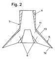
- Fig. 2
- einen Schnitt durch einen bekannten Verteiler für eine Separatortrommel;
- Fig. 3
- eine perspektivische Ansicht eines Strömungskanals eines erfindungsgemäßen Verteilers.
-
Fig. 1 zeigt eine Separatortrommel 1 mit einer vertikalen Drehachse D, die ein zentrisches Zulaufrohr 2 aufweist, das in einen Verteiler 3 mündet. Der Verteiler 3 weist an seinem Eintritt einen zentrischen Eintrittsrohrabschnitt 4 in axialer Verlängerung des Zulaufrohrs 2 auf, der in einen Fußabschnitt 5 übergeht. - An den zentrischen Eintrittsrohrabschnitt 4 schließen im Fußabschnitt 5 umfangsverteilt winklig, vorzugsweise spitzwinklig oder rechtwinklig zur Drehachse radial nach außen erstreckende Strömungskanäle 6 an. Die Strömungskanäle 6 verlaufen im Bezug auf die Drehachse hier schräg nach unten, sie könnten aber auch spitzwinklig vom Zulaufrohrabschnitt 4 schräg nach oben gerichtet sein.
- In der Trommel 1 ist ein Trenntellerstapel 7 aus Trennteller 8 angeordnet. Ableitungen 9, 10 für wenigstens eine oder mehrere flüssige und vorzugsweise eine feste Phase dienen zur Ableitung der getrennten und/oder geklärten Phasen aus der Trommel 1. Der Verteiler 4 ist mit geeigneten Mitteln an der Trommel 1 befestigt. Der Produktfluss ist mit Pfeilen angedeutet.
- Die Strömungskanäle 6 erstrecken sich in dem Verteilerfuß 5 von Eintrittsöffnungen 11 in die Strömungskanäle bis zu Austrittsöffnungen 12 aus den Strömungskanälen 6 in den Innenraum der Schleudertrommel.
- Nach oben hin werden die Strömungskanäle von einer hier konischen Verteilerfußabdeckung 13 abgedeckt. Seitlich bzw. in Umfangsrichtung werden die Strömungskanäle 6 von Wandabschnitten 14 begrenzt. Jedenfalls an der Unterseite ist die Verteilerfußabdeckung tellerartig ausgebildet.
- In dem Bereich zwischen den Eintrittsöffnungen 11 und den Austrittsöffnungen 12 sind in den Strömungskanälen, von denen
Fig. 3 einen nach Art eines Blickes unter den Verteilerfuß 13 veranschaulicht, mehrere Stauwehre 15 angeordnet, welche den Querschnitt des Strömungskanals in diesem Bereich verengen. - Vorzugsweise sind die Stauwehre 15 als Rippen ausgebildet. Diese Rippen 15 sind vorzugsweise im Übergangsbereich jeweils zwischen einer der Seitenwände 14 und der Verteilerfußabdeckung 13 angeordnet bzw. ausgebildet, und zwar insbesondere in dem Übergangsbereich zwischen der im Betrieb in Drehrichtung U hinteren Wandabschnitt 14 und der Verteilerfußabdeckung 13. In Umfangsrichtung sind die Strömungskanäle 6 hier durch die Wandabschnitte 14 voneinander getrennt.
- Besonders bevorzugt weisen die Rippen in diesem Bereich einen dreiecksförmigen Abschnitt 16 auf, der sich an der Unterseite der Verteilerfußabdeckung 13 über einen Teil der Umfangslänge des Strömungskanals 6 erstreckt und dann in einen Stegabschnitt 17 übergeht. Der im Wesentlichen dreieckige Abschnitt 16 kann im Bereich seiner Grundseite 18 auch beispielsweise eine Bogenform aufweisen. Die Höhe H der Abschnitte 15 und 16 beträgt wenigstens 2 mm oder mehr. Der Abschnitt 16 erstreckt sich vorzugsweise bis zur in Umfangsrichtung nächsten Seitenwand 14. Vorzugsweise werden mehr als drei Wehre in jedem Strömungskanal 6 verteilt. Ziel ist es, dass sich möglichst mit der Zeit eine durchgehende verschleißschützende Beschichtung an der Unterseite der Verteilerfußabdeckung 13 ausbildet.
- In Strömungsrichtung - die radial von innen nach außen verläuft - betrachtet bilden sich bei Strömungsrichtung von innen nach außen vor den Rippen 15 in den Strömungskanälen Materialanhäufungen bzw. eine Materialschicht aus dem Feststoff aus, die bei der Verarbeitung von hygienisch nicht kritischen Produkten einerseits unproblematisch ist und die andererseits vorteilhaft als Verschleißschutz und damit lebensdauererhöhend wirkt.
-
Separatortrommel 1 Zulaufrohr 2 Verteiler 3 Eintrittsrohrabschnitt 4 Fußabschnitt 5 Strömungskanäle 6 Trenntellerstapel 7 Trennteller 8 Ableitungen 9, 10 Eintrittsöffnungen 11 Austrittsöffnungen 12 Verteilerfußabdeckung 13 Wandabschnitte 14 Stauwehre 15 dreieckiger Abschnitt 16 Stegabschnitt 17 Fußabschnitt 18 Drehachse D Höhe H
Claims (11)
- Drehbare Separatortrommel (1) mit einer vertikalen Drehachse (D), die wenigstens einen Strömungskanal mit einer Eintrittsöffnung und einer Austrittsöffnung aufweist, dadurch gekennzeichnet, dass in dem Bereich zwischen der Eintrittsöffnung (11) und der Austrittsöffnung (12) in dem wenigstens einen Strömungskanal wenigstens ein Stauwehr (15) angeordnet ist, vor dem sich im Betrieb bei der Verarbeitung eines feststoffhaltigen Produktes eine Feststoffanhäufung ausbildet.
- Drehbare Separatortrommel (1) nach Anspruch 1, dadurch gekennzeichnet, dass sie ein an wenigstens einer seiner Flächen tellerartiges Bauteil aufweist, an dem der Strömungskanal mit der Eintrittsöffnung und dem wenigstens einen Strömungskanal mit dem wenigstens einen Stauwehr (15) angeordnet ist, vor dem sich im Betrieb bei der Verarbeitung des feststoffhaltigen Produktes die Feststoffanhäufung ausbildet.
- Separatortrommel nach Anspruch 2, dadurch gekennzeichnet, dass das tellerartige Bauteil ein Fußabschnitt (5), insbesondere eine Verteilerfußabdeckung (13) eines Verteilers (3) ist, der mit der Trommel (1) drehfest verbunden ist, wobei der Fußabschnitt (5) mit wenigstens einem oder mehreren der Strömungskanäle (6) versehen ist, die sich winklig zur Drehachse vorzugsweise radial nach außen erstrecken und wobei in dem Bereich zwischen der Eintrittsöffnung (11) und der Austrittsöffnung (12) in dem wenigstens einen Strömungskanal (6) wenigstens eines der Stauwehre (15) angeordnet ist.
- Drehbare Separatortrommel (1) nach Anspruch 2, dadurch gekennzeichnet, dass das tellerartige Bauelement ein Scheideteller, ein Trommelteil oder ein Blech ist, welches an einer Innenfläche eines Trommelteils angebracht ist.
- Separatortrommel nach einem der vorstehenden Ansprüche, dadurch gekennzeichnet, dass in den Strömungskanälen (6) jeweils mehrere der Stauwehre (15) angeordnet sind.
- Separatortrommel nach Anspruch 5, dadurch gekennzeichnet, dass in den Strömungskanälen (6) jeweils mehrere der Stauwehre (15) radial nach außen hintereinander angeordnet sind.
- Separatortrommel nach einem der vorstehenden Ansprüche, dadurch gekennzeichnet, dass das/die Stauwehr(e) (15) als Rippe(n) ausgebildet ist/sind.
- Separatortrommel nach Anspruch 7, dadurch gekennzeichnet, dass die wenigstens eine Rippe im Übergangsbereich zwischen einer der Seitenwände (14) und einer Verteilerfußabdeckung (13) eines Verteilers ausgebildet ist.
- Separatortrommel nach einem der vorstehenden Ansprüche 7 oder 8, dadurch gekennzeichnet, dass die wenigstens eine Rippe an der Unterseite der Verteilerfußabdeckung (13) ausgebildet ist.
- Separatortrommel nach einem der vorstehenden Ansprüche 7 bis 9, dadurch gekennzeichnet, dass die wenigstens eine Rippe im Übergangsbereich zwischen dem im Betrieb in Drehrichtung (u) hinteren Wandabschnitt (14) und der Verteilerfußabdeckung (13) ausgebildet ist.
- Separatortrommel nach einem der vorstehenden Ansprüche 7 bis 10, dadurch gekennzeichnet, dass die wenigstens eine Rippe einen dreieckigen Abschnitt (16) aufweist, der an der Unterseite der Verteilerfußabdeckung in einen Stegabschnitt (17) übergeht.
Applications Claiming Priority (1)
| Application Number | Priority Date | Filing Date | Title |
|---|---|---|---|
| PCT/EP2008/005152 WO2009155943A1 (de) | 2008-06-25 | 2008-06-25 | Separatortrommel mit verteiler |
Publications (2)
| Publication Number | Publication Date |
|---|---|
| EP2321056A1 EP2321056A1 (de) | 2011-05-18 |
| EP2321056B1 true EP2321056B1 (de) | 2013-05-22 |
Family
ID=40409797
Family Applications (1)
| Application Number | Title | Priority Date | Filing Date |
|---|---|---|---|
| EP08773657.5A Not-in-force EP2321056B1 (de) | 2008-06-25 | 2008-06-25 | Separatortrommel mit verteiler |
Country Status (6)
| Country | Link |
|---|---|
| US (1) | US8585566B2 (de) |
| EP (1) | EP2321056B1 (de) |
| CN (1) | CN102076420B (de) |
| BR (1) | BRPI0822908B1 (de) |
| CA (1) | CA2727279C (de) |
| WO (1) | WO2009155943A1 (de) |
Families Citing this family (7)
| Publication number | Priority date | Publication date | Assignee | Title |
|---|---|---|---|---|
| US8585566B2 (en) * | 2008-06-25 | 2013-11-19 | Gea Mechanical Equipment Gmbh | Separator drum having a distributor flow channel with a dam |
| DE102009032617A1 (de) * | 2009-07-10 | 2011-01-13 | Gea Westfalia Separator Gmbh | Separator mit vertikaler Drehachse |
| BR112014009743A2 (pt) * | 2011-11-04 | 2017-05-02 | Cummins Filtration Ip Inc | separador giratório para separar líquido de mistura fluida |
| EP2628544B1 (de) * | 2012-02-15 | 2015-03-25 | Alfa Laval Corporate AB | Zentrifugaltrenner mit Einlassanordnung |
| EP2664383A1 (de) * | 2012-05-15 | 2013-11-20 | Miltenyi Biotec GmbH | Zentrifugationskammer mit Deflektorabschirmungen |
| CN105413894A (zh) * | 2015-12-15 | 2016-03-23 | 宜兴市华鼎粮食机械有限公司 | 一种带新型分配器的碟式离心机转鼓 |
| CN113058319B (zh) * | 2021-04-13 | 2022-07-29 | 四川红土地农业开发有限公司 | 一种紫薯红酒加工用过滤装置及使用方法 |
Family Cites Families (26)
| Publication number | Priority date | Publication date | Assignee | Title |
|---|---|---|---|---|
| US801068A (en) * | 1904-06-25 | 1905-10-03 | James H Fleming | Centrifugal cream-separator. |
| US801069A (en) * | 1904-07-01 | 1905-10-03 | James H Fleming | Centrifugal cream-separator. |
| US1760071A (en) * | 1926-09-17 | 1930-05-27 | Standard Brands Inc | Centrifugal separator |
| US2104683A (en) * | 1933-07-06 | 1938-01-04 | Rosen Van | Dust separator |
| US2243697A (en) * | 1938-11-28 | 1941-05-27 | Laval Separator Co De | Liquid supply means for centrifugal separators |
| US2302381A (en) * | 1940-04-12 | 1942-11-17 | Sharples Corp | Centrifugal separator |
| US2645415A (en) * | 1950-03-07 | 1953-07-14 | Laval Separator Co De | Centrifugal bowl |
| NL136377C (de) | 1961-08-01 | 1900-01-01 | ||
| DE1896480U (de) | 1964-05-15 | 1964-07-09 | Krauss Maffei Ag | Stehend gelagerte schleudertrommel fuer selbstaustragende siebzentrifugen. |
| SE334847B (de) * | 1969-05-08 | 1971-05-03 | Alfa Laval Ab | |
| US3963175A (en) * | 1974-07-31 | 1976-06-15 | Ametek, Inc. | Feedcone with accelerator vanes for imperforate basket |
| DE3019737C2 (de) * | 1980-05-23 | 1982-09-02 | Westfalia Separator Ag, 4740 Oelde | Schleudertrommel zum Klären und Trennen von Schleuderflüssigkeiten |
| DE3042948A1 (de) | 1980-11-14 | 1982-07-08 | Salzgitter Maschinen Und Anlagen Ag, 3320 Salzgitter | Schubzentrifuge |
| US4430071A (en) * | 1982-05-27 | 1984-02-07 | Dorr-Oliver Incorporated | Feed seal for bottom feed centrifuge |
| DE3305215C2 (de) * | 1983-02-16 | 1986-04-10 | Westfalia Separator Ag, 4740 Oelde | Schleudertrommel zum Klären und Trennen von Schleuderflüssigkeiten |
| SE450093B (sv) * | 1985-10-30 | 1987-06-09 | Alfa Laval Separation Ab | Inloppsanordning vid centrifugalseparator |
| DE3805016A1 (de) * | 1987-04-24 | 1988-11-03 | Westfalia Separator Ag | Schleudertrommel |
| DE3713719C1 (en) * | 1987-04-24 | 1988-04-07 | Westfalia Separator Ag | Centrifuged drum |
| SE465501B (sv) * | 1990-02-15 | 1991-09-23 | Alfa Laval Separation Ab | Centrifugalseparator med inloppskammare |
| CA2131738C (en) * | 1993-11-17 | 2001-09-04 | Lonny R. Kelley | Flow enhanced one-pass centrifuge separator |
| DE19519693C1 (de) | 1995-05-30 | 1996-08-22 | Westfalia Separator Ag | Verfahren und Vorrichtung zum Füllen einer selbstentleerenden Schleudertrommel |
| SE524921C2 (sv) * | 2003-11-07 | 2004-10-26 | Alfa Laval Corp Ab | En medbringningsanordning för en centrifugator |
| DE102006047478A1 (de) * | 2005-10-06 | 2007-04-12 | Westfalia Separator Ag | Separatortrommel mit optimiertem Verteiler |
| DE102007028102A1 (de) * | 2007-06-19 | 2008-12-24 | Westfalia Separator Gmbh | Separatortrommel mit Verteiler |
| US8585566B2 (en) * | 2008-06-25 | 2013-11-19 | Gea Mechanical Equipment Gmbh | Separator drum having a distributor flow channel with a dam |
| DE102009032617A1 (de) * | 2009-07-10 | 2011-01-13 | Gea Westfalia Separator Gmbh | Separator mit vertikaler Drehachse |
-
2008
- 2008-06-25 US US13/000,762 patent/US8585566B2/en not_active Expired - Fee Related
- 2008-06-25 WO PCT/EP2008/005152 patent/WO2009155943A1/de not_active Ceased
- 2008-06-25 EP EP08773657.5A patent/EP2321056B1/de not_active Not-in-force
- 2008-06-25 CN CN2008801299899A patent/CN102076420B/zh not_active Expired - Fee Related
- 2008-06-25 CA CA2727279A patent/CA2727279C/en not_active Expired - Fee Related
- 2008-06-25 BR BRPI0822908A patent/BRPI0822908B1/pt not_active IP Right Cessation
Also Published As
| Publication number | Publication date |
|---|---|
| CA2727279C (en) | 2015-02-24 |
| BRPI0822908B1 (pt) | 2020-04-28 |
| BRPI0822908A2 (pt) | 2015-06-30 |
| US8585566B2 (en) | 2013-11-19 |
| CN102076420A (zh) | 2011-05-25 |
| EP2321056A1 (de) | 2011-05-18 |
| CN102076420B (zh) | 2012-06-27 |
| US20110215044A1 (en) | 2011-09-08 |
| WO2009155943A1 (de) | 2009-12-30 |
| CA2727279A1 (en) | 2009-12-30 |
Similar Documents
| Publication | Publication Date | Title |
|---|---|---|
| EP2598251B1 (de) | Vollmantel-schneckenzentrifuge mit überlaufwehr | |
| EP2872256B1 (de) | Vollmantel-schneckenzentrifuge mit überlaufwehr | |
| WO2009155943A1 (de) | Separatortrommel mit verteiler | |
| DE69530977T2 (de) | Rotierender scheibenfilter | |
| DE102004037925A1 (de) | Separator mit einer Schleudertrommel mit einem Tellerpaket | |
| EP2062650B1 (de) | Zentrifuge mit einem Trenntellerpaket und Trennteller | |
| EP2451585B1 (de) | Separator mit vertikaler drehachse | |
| EP2352598B1 (de) | Zentrifuge mit einstückiger abscheideeinrichtung | |
| EP3618968A1 (de) | Dekanterzentrifuge | |
| EP1345700A1 (de) | Vollmantel-schneckenzentrifuge mit tellereinsatz | |
| DE20010743U1 (de) | Zentrifuge mit doppeltem Zulauf | |
| EP0710504A1 (de) | Schubzentrifuge | |
| DE102008038645A1 (de) | Grobgutseparator zum Trennen von Grobgut aus einem Schüttgut | |
| EP1786565B1 (de) | Selbstentleerender separator mit tellerpaket | |
| EP2050505B1 (de) | Zentrifuge und Trennteller | |
| WO2011117090A1 (de) | Vollmantel-schneckenzentrifuge | |
| DE102018114841A1 (de) | Zentrifuge mit einer Schälscheibe | |
| DE202021104728U1 (de) | Trennteller, Trenntellerstapel sowie Zentrifuge mit dem Trenntellerstapel | |
| DE102007028102A1 (de) | Separatortrommel mit Verteiler | |
| DE3800843A1 (de) | Turbo-windsichter | |
| EP0678583B1 (de) | Verfahren zur Fest-Flüssig-Extrahierung und Extraktionsturm zur Durchführung des Verfahrens | |
| DE2349941A1 (de) | Verfahren und vorrichtung zur nassfeinsiebung | |
| EP2571621B1 (de) | Vollmantel-schneckenzentrifuge | |
| DE3041210C2 (de) | Selbstentleerende Zentrifuge | |
| EP2566626B2 (de) | Düsenseparator und verfahren zum ableiten einer feststoffphase aus dem düsenseparator |
Legal Events
| Date | Code | Title | Description |
|---|---|---|---|
| PUAI | Public reference made under article 153(3) epc to a published international application that has entered the european phase |
Free format text: ORIGINAL CODE: 0009012 |
|
| 17P | Request for examination filed |
Effective date: 20110113 |
|
| AK | Designated contracting states |
Kind code of ref document: A1 Designated state(s): AT BE BG CH CY CZ DE DK EE ES FI FR GB GR HR HU IE IS IT LI LT LU LV MC MT NL NO PL PT RO SE SI SK TR |
|
| AX | Request for extension of the european patent |
Extension state: AL BA MK RS |
|
| 17Q | First examination report despatched |
Effective date: 20110715 |
|
| DAX | Request for extension of the european patent (deleted) | ||
| REG | Reference to a national code |
Ref country code: DE Ref legal event code: R079 Ref document number: 502008009986 Country of ref document: DE Free format text: PREVIOUS MAIN CLASS: B04B0001060000 Ipc: B04B0011060000 |
|
| RIC1 | Information provided on ipc code assigned before grant |
Ipc: B04B 1/08 20060101ALI20121130BHEP Ipc: B04B 11/06 20060101AFI20121130BHEP |
|
| GRAP | Despatch of communication of intention to grant a patent |
Free format text: ORIGINAL CODE: EPIDOSNIGR1 |
|
| GRAS | Grant fee paid |
Free format text: ORIGINAL CODE: EPIDOSNIGR3 |
|
| GRAA | (expected) grant |
Free format text: ORIGINAL CODE: 0009210 |
|
| AK | Designated contracting states |
Kind code of ref document: B1 Designated state(s): AT BE BG CH CY CZ DE DK EE ES FI FR GB GR HR HU IE IS IT LI LT LU LV MC MT NL NO PL PT RO SE SI SK TR |
|
| REG | Reference to a national code |
Ref country code: GB Ref legal event code: FG4D Free format text: NOT ENGLISH |
|
| REG | Reference to a national code |
Ref country code: CH Ref legal event code: EP |
|
| REG | Reference to a national code |
Ref country code: AT Ref legal event code: REF Ref document number: 612916 Country of ref document: AT Kind code of ref document: T Effective date: 20130615 |
|
| REG | Reference to a national code |
Ref country code: IE Ref legal event code: FG4D Free format text: LANGUAGE OF EP DOCUMENT: GERMAN |
|
| REG | Reference to a national code |
Ref country code: DE Ref legal event code: R096 Ref document number: 502008009986 Country of ref document: DE Effective date: 20130718 |
|
| REG | Reference to a national code |
Ref country code: SE Ref legal event code: TRGR |
|
| REG | Reference to a national code |
Ref country code: LT Ref legal event code: MG4D |
|
| PG25 | Lapsed in a contracting state [announced via postgrant information from national office to epo] |
Ref country code: FI Free format text: LAPSE BECAUSE OF FAILURE TO SUBMIT A TRANSLATION OF THE DESCRIPTION OR TO PAY THE FEE WITHIN THE PRESCRIBED TIME-LIMIT Effective date: 20130522 Ref country code: ES Free format text: LAPSE BECAUSE OF FAILURE TO SUBMIT A TRANSLATION OF THE DESCRIPTION OR TO PAY THE FEE WITHIN THE PRESCRIBED TIME-LIMIT Effective date: 20130902 Ref country code: LT Free format text: LAPSE BECAUSE OF FAILURE TO SUBMIT A TRANSLATION OF THE DESCRIPTION OR TO PAY THE FEE WITHIN THE PRESCRIBED TIME-LIMIT Effective date: 20130522 Ref country code: SI Free format text: LAPSE BECAUSE OF FAILURE TO SUBMIT A TRANSLATION OF THE DESCRIPTION OR TO PAY THE FEE WITHIN THE PRESCRIBED TIME-LIMIT Effective date: 20130522 Ref country code: GR Free format text: LAPSE BECAUSE OF FAILURE TO SUBMIT A TRANSLATION OF THE DESCRIPTION OR TO PAY THE FEE WITHIN THE PRESCRIBED TIME-LIMIT Effective date: 20130823 Ref country code: IS Free format text: LAPSE BECAUSE OF FAILURE TO SUBMIT A TRANSLATION OF THE DESCRIPTION OR TO PAY THE FEE WITHIN THE PRESCRIBED TIME-LIMIT Effective date: 20130922 Ref country code: PT Free format text: LAPSE BECAUSE OF FAILURE TO SUBMIT A TRANSLATION OF THE DESCRIPTION OR TO PAY THE FEE WITHIN THE PRESCRIBED TIME-LIMIT Effective date: 20130923 Ref country code: NO Free format text: LAPSE BECAUSE OF FAILURE TO SUBMIT A TRANSLATION OF THE DESCRIPTION OR TO PAY THE FEE WITHIN THE PRESCRIBED TIME-LIMIT Effective date: 20130822 |
|
| REG | Reference to a national code |
Ref country code: NL Ref legal event code: VDEP Effective date: 20130522 |
|
| PG25 | Lapsed in a contracting state [announced via postgrant information from national office to epo] |
Ref country code: PL Free format text: LAPSE BECAUSE OF FAILURE TO SUBMIT A TRANSLATION OF THE DESCRIPTION OR TO PAY THE FEE WITHIN THE PRESCRIBED TIME-LIMIT Effective date: 20130522 Ref country code: HR Free format text: LAPSE BECAUSE OF FAILURE TO SUBMIT A TRANSLATION OF THE DESCRIPTION OR TO PAY THE FEE WITHIN THE PRESCRIBED TIME-LIMIT Effective date: 20130522 Ref country code: BG Free format text: LAPSE BECAUSE OF FAILURE TO SUBMIT A TRANSLATION OF THE DESCRIPTION OR TO PAY THE FEE WITHIN THE PRESCRIBED TIME-LIMIT Effective date: 20130822 |
|
| BERE | Be: lapsed |
Owner name: GEA MECHANICAL EQUIPMENT G.M.B.H. Effective date: 20130630 |
|
| PG25 | Lapsed in a contracting state [announced via postgrant information from national office to epo] |
Ref country code: LV Free format text: LAPSE BECAUSE OF FAILURE TO SUBMIT A TRANSLATION OF THE DESCRIPTION OR TO PAY THE FEE WITHIN THE PRESCRIBED TIME-LIMIT Effective date: 20130522 |
|
| PG25 | Lapsed in a contracting state [announced via postgrant information from national office to epo] |
Ref country code: EE Free format text: LAPSE BECAUSE OF FAILURE TO SUBMIT A TRANSLATION OF THE DESCRIPTION OR TO PAY THE FEE WITHIN THE PRESCRIBED TIME-LIMIT Effective date: 20130522 Ref country code: DK Free format text: LAPSE BECAUSE OF FAILURE TO SUBMIT A TRANSLATION OF THE DESCRIPTION OR TO PAY THE FEE WITHIN THE PRESCRIBED TIME-LIMIT Effective date: 20130522 Ref country code: CZ Free format text: LAPSE BECAUSE OF FAILURE TO SUBMIT A TRANSLATION OF THE DESCRIPTION OR TO PAY THE FEE WITHIN THE PRESCRIBED TIME-LIMIT Effective date: 20130522 Ref country code: SK Free format text: LAPSE BECAUSE OF FAILURE TO SUBMIT A TRANSLATION OF THE DESCRIPTION OR TO PAY THE FEE WITHIN THE PRESCRIBED TIME-LIMIT Effective date: 20130522 |
|
| REG | Reference to a national code |
Ref country code: CH Ref legal event code: PL |
|
| PG25 | Lapsed in a contracting state [announced via postgrant information from national office to epo] |
Ref country code: RO Free format text: LAPSE BECAUSE OF FAILURE TO SUBMIT A TRANSLATION OF THE DESCRIPTION OR TO PAY THE FEE WITHIN THE PRESCRIBED TIME-LIMIT Effective date: 20130522 Ref country code: MC Free format text: LAPSE BECAUSE OF FAILURE TO SUBMIT A TRANSLATION OF THE DESCRIPTION OR TO PAY THE FEE WITHIN THE PRESCRIBED TIME-LIMIT Effective date: 20130522 Ref country code: NL Free format text: LAPSE BECAUSE OF FAILURE TO SUBMIT A TRANSLATION OF THE DESCRIPTION OR TO PAY THE FEE WITHIN THE PRESCRIBED TIME-LIMIT Effective date: 20130522 Ref country code: IT Free format text: LAPSE BECAUSE OF FAILURE TO SUBMIT A TRANSLATION OF THE DESCRIPTION OR TO PAY THE FEE WITHIN THE PRESCRIBED TIME-LIMIT Effective date: 20130522 |
|
| REG | Reference to a national code |
Ref country code: IE Ref legal event code: MM4A |
|
| PLBE | No opposition filed within time limit |
Free format text: ORIGINAL CODE: 0009261 |
|
| STAA | Information on the status of an ep patent application or granted ep patent |
Free format text: STATUS: NO OPPOSITION FILED WITHIN TIME LIMIT |
|
| PG25 | Lapsed in a contracting state [announced via postgrant information from national office to epo] |
Ref country code: BE Free format text: LAPSE BECAUSE OF NON-PAYMENT OF DUE FEES Effective date: 20130630 |
|
| GBPC | Gb: european patent ceased through non-payment of renewal fee |
Effective date: 20130822 |
|
| 26N | No opposition filed |
Effective date: 20140225 |
|
| PG25 | Lapsed in a contracting state [announced via postgrant information from national office to epo] |
Ref country code: CH Free format text: LAPSE BECAUSE OF NON-PAYMENT OF DUE FEES Effective date: 20130630 Ref country code: IE Free format text: LAPSE BECAUSE OF NON-PAYMENT OF DUE FEES Effective date: 20130625 Ref country code: LI Free format text: LAPSE BECAUSE OF NON-PAYMENT OF DUE FEES Effective date: 20130630 |
|
| REG | Reference to a national code |
Ref country code: DE Ref legal event code: R097 Ref document number: 502008009986 Country of ref document: DE Effective date: 20140225 |
|
| PG25 | Lapsed in a contracting state [announced via postgrant information from national office to epo] |
Ref country code: GB Free format text: LAPSE BECAUSE OF NON-PAYMENT OF DUE FEES Effective date: 20130822 |
|
| REG | Reference to a national code |
Ref country code: AT Ref legal event code: MM01 Ref document number: 612916 Country of ref document: AT Kind code of ref document: T Effective date: 20130625 |
|
| PG25 | Lapsed in a contracting state [announced via postgrant information from national office to epo] |
Ref country code: AT Free format text: LAPSE BECAUSE OF NON-PAYMENT OF DUE FEES Effective date: 20130625 |
|
| PG25 | Lapsed in a contracting state [announced via postgrant information from national office to epo] |
Ref country code: MT Free format text: LAPSE BECAUSE OF FAILURE TO SUBMIT A TRANSLATION OF THE DESCRIPTION OR TO PAY THE FEE WITHIN THE PRESCRIBED TIME-LIMIT Effective date: 20130522 |
|
| PG25 | Lapsed in a contracting state [announced via postgrant information from national office to epo] |
Ref country code: CY Free format text: LAPSE BECAUSE OF FAILURE TO SUBMIT A TRANSLATION OF THE DESCRIPTION OR TO PAY THE FEE WITHIN THE PRESCRIBED TIME-LIMIT Effective date: 20130522 Ref country code: TR Free format text: LAPSE BECAUSE OF FAILURE TO SUBMIT A TRANSLATION OF THE DESCRIPTION OR TO PAY THE FEE WITHIN THE PRESCRIBED TIME-LIMIT Effective date: 20130522 |
|
| PG25 | Lapsed in a contracting state [announced via postgrant information from national office to epo] |
Ref country code: LU Free format text: LAPSE BECAUSE OF NON-PAYMENT OF DUE FEES Effective date: 20130625 Ref country code: HU Free format text: LAPSE BECAUSE OF FAILURE TO SUBMIT A TRANSLATION OF THE DESCRIPTION OR TO PAY THE FEE WITHIN THE PRESCRIBED TIME-LIMIT; INVALID AB INITIO Effective date: 20080625 |
|
| REG | Reference to a national code |
Ref country code: FR Ref legal event code: PLFP Year of fee payment: 9 |
|
| REG | Reference to a national code |
Ref country code: FR Ref legal event code: PLFP Year of fee payment: 10 |
|
| REG | Reference to a national code |
Ref country code: FR Ref legal event code: PLFP Year of fee payment: 11 |
|
| PGFP | Annual fee paid to national office [announced via postgrant information from national office to epo] |
Ref country code: FR Payment date: 20210630 Year of fee payment: 14 Ref country code: DE Payment date: 20210628 Year of fee payment: 14 |
|
| PGFP | Annual fee paid to national office [announced via postgrant information from national office to epo] |
Ref country code: SE Payment date: 20210625 Year of fee payment: 14 |
|
| REG | Reference to a national code |
Ref country code: DE Ref legal event code: R119 Ref document number: 502008009986 Country of ref document: DE |
|
| REG | Reference to a national code |
Ref country code: SE Ref legal event code: EUG |
|
| PG25 | Lapsed in a contracting state [announced via postgrant information from national office to epo] |
Ref country code: SE Free format text: LAPSE BECAUSE OF NON-PAYMENT OF DUE FEES Effective date: 20220626 Ref country code: FR Free format text: LAPSE BECAUSE OF NON-PAYMENT OF DUE FEES Effective date: 20220630 |
|
| PG25 | Lapsed in a contracting state [announced via postgrant information from national office to epo] |
Ref country code: DE Free format text: LAPSE BECAUSE OF NON-PAYMENT OF DUE FEES Effective date: 20230103 |