EP2566626B2 - Düsenseparator und verfahren zum ableiten einer feststoffphase aus dem düsenseparator - Google Patents
Düsenseparator und verfahren zum ableiten einer feststoffphase aus dem düsenseparator Download PDFInfo
- Publication number
- EP2566626B2 EP2566626B2 EP11715533.3A EP11715533A EP2566626B2 EP 2566626 B2 EP2566626 B2 EP 2566626B2 EP 11715533 A EP11715533 A EP 11715533A EP 2566626 B2 EP2566626 B2 EP 2566626B2
- Authority
- EP
- European Patent Office
- Prior art keywords
- drum
- washing liquid
- supply pipes
- nozzle separator
- nozzle
- Prior art date
- Legal status (The legal status is an assumption and is not a legal conclusion. Google has not performed a legal analysis and makes no representation as to the accuracy of the status listed.)
- Active
Links
- 238000000034 method Methods 0.000 title claims description 5
- 239000007790 solid phase Substances 0.000 title claims description 5
- 238000005406 washing Methods 0.000 claims description 41
- 239000007788 liquid Substances 0.000 claims description 38
- 239000007787 solid Substances 0.000 claims description 12
- 239000000725 suspension Substances 0.000 claims description 9
- 230000002093 peripheral effect Effects 0.000 claims description 8
- 238000012856 packing Methods 0.000 claims description 3
- 239000012071 phase Substances 0.000 description 6
- 239000000047 product Substances 0.000 description 6
- 230000000694 effects Effects 0.000 description 3
- 239000002253 acid Substances 0.000 description 2
- 230000001419 dependent effect Effects 0.000 description 2
- 239000012263 liquid product Substances 0.000 description 2
- 150000003839 salts Chemical class 0.000 description 2
- 239000000243 solution Substances 0.000 description 2
- 238000009795 derivation Methods 0.000 description 1
- 239000003599 detergent Substances 0.000 description 1
- 238000010586 diagram Methods 0.000 description 1
- 239000010432 diamond Substances 0.000 description 1
- 238000007599 discharging Methods 0.000 description 1
- 238000002474 experimental method Methods 0.000 description 1
- 230000001771 impaired effect Effects 0.000 description 1
- 239000007791 liquid phase Substances 0.000 description 1
- 239000012452 mother liquor Substances 0.000 description 1
- 239000000700 radioactive tracer Substances 0.000 description 1
- 230000002787 reinforcement Effects 0.000 description 1
- 239000012266 salt solution Substances 0.000 description 1
- 238000005201 scrubbing Methods 0.000 description 1
- 238000004062 sedimentation Methods 0.000 description 1
- 238000005507 spraying Methods 0.000 description 1
Images


Classifications
-
- B—PERFORMING OPERATIONS; TRANSPORTING
- B04—CENTRIFUGAL APPARATUS OR MACHINES FOR CARRYING-OUT PHYSICAL OR CHEMICAL PROCESSES
- B04B—CENTRIFUGES
- B04B1/00—Centrifuges with rotary bowls provided with solid jackets for separating predominantly liquid mixtures with or without solid particles
- B04B1/10—Centrifuges with rotary bowls provided with solid jackets for separating predominantly liquid mixtures with or without solid particles with discharging outlets in the plane of the maximum diameter of the bowl
-
- B—PERFORMING OPERATIONS; TRANSPORTING
- B04—CENTRIFUGAL APPARATUS OR MACHINES FOR CARRYING-OUT PHYSICAL OR CHEMICAL PROCESSES
- B04B—CENTRIFUGES
- B04B11/00—Feeding, charging, or discharging bowls
- B04B11/02—Continuous feeding or discharging; Control arrangements therefor
-
- B—PERFORMING OPERATIONS; TRANSPORTING
- B04—CENTRIFUGAL APPARATUS OR MACHINES FOR CARRYING-OUT PHYSICAL OR CHEMICAL PROCESSES
- B04B—CENTRIFUGES
- B04B15/00—Other accessories for centrifuges
- B04B15/12—Other accessories for centrifuges for drying or washing the separated solid particles
-
- B—PERFORMING OPERATIONS; TRANSPORTING
- B04—CENTRIFUGAL APPARATUS OR MACHINES FOR CARRYING-OUT PHYSICAL OR CHEMICAL PROCESSES
- B04B—CENTRIFUGES
- B04B3/00—Centrifuges with rotary bowls in which solid particles or bodies become separated by centrifugal force and simultaneous sifting or filtering
- B04B3/02—Centrifuges with rotary bowls in which solid particles or bodies become separated by centrifugal force and simultaneous sifting or filtering discharging solid particles from the bowl by means coaxial with the bowl axis and moving to and fro, i.e. push-type centrifuges
Definitions
- the invention relates to a nozzle separator according to the preamble of claim 1 and a method according to the preamble of claim 6.
- the US 4 286 748 A called, which discloses a centrifuge-type washing device.
- the technological background of spraying devices is also the US 1 714 232 A cited.
- replacement wash in which a washing liquid is conducted into the interior of the drum with recirculation lines extending radially outward in the interior of the drum, so that these enter into the interior of the drum radially and radially having an axial velocity component.
- the separated from the mother liquor solid phase is taken up by the washing solution and ejected as a washed washing suspension from the drum via nozzles as a nozzle phase from the drum ( Fig. 2 ).
- the invention aims to reduce this problem.
- the g-field is amplified by the additional peripheral speed.
- the outlet openings of the supply pipes are located in the circumferential direction between the Feststoffaustragsö réelleen to achieve a particularly good effect of the type described above.
- they can also lie radially in the extension of the outlet openings.
- Fig. 2 shows a section through a lower part 1 designed as a nozzle drum for continuous operation Separatortrommel 2 with a vertical axis of rotation.
- the separator drum 2 has solids discharge nozzles 3 in the region of its largest diameter.
- the nozzle drum is rotatable by means of a drive, not shown here and has next to the in Fig. 2 components shown an inlet for a suspension to be processed, preferably a plate package of separating plates and one or more devices for the derivation of at least one liquid phase. Such devices are familiar to the skilled worker and require no further explanation here.
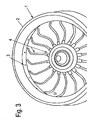
- the separator drum has an arrangement 4 for adding washing liquid into the interior of the drum (see also for a better understanding Fig. 3 ).
- This arrangement has an inlet for washing liquid (not visible here), which may be formed, for example, concentrically to the inlet (pipe) for the suspension to be processed.
- the inlet for washing liquid opens into a distributor 5 (see also Fig. 3 ), which has a plurality of circumferentially distributed outlet openings which open into radially in the drum outwardly extending supply pipes 6 for distribution and supply of the washing liquid into the drum interior.
- the distribution pipes 6 extend in the prior art in the drum radially outward until just before the Feststoffaustragsdüsen 3 in the drum wall 8. Between adjacent Feststoffaustragsdüsen 4 wall reinforcements in the form of packing 9 are arranged circumferentially distributed here, in the interior of the separator drum. 2 protrude and which direct out of the inlet pipes 1 washing liquid in the direction of the solids discharge nozzles 3.
- the supply pipes 6 for the washing liquid serve to guide the washing liquid, usually a specifically lighter washing acid, into the interior of the drum in the region shortly before the solids discharge nozzles 3.
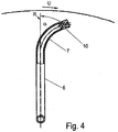
- inlet pipes 6, which extend radially outward in the interior of the drum, in their radially outer region with an arcuate deflection section 7 which serves to redirect the washing liquid from the radial direction in the circumferential direction U (in the direction of rotation).
- This deflection section 7 is after Fig.1 formed as a 90 ° -Rohrbogen, wherein the outlet opening of the pipe bend is directed in the circumferential direction of rotation U, so that the washing liquid leaves the deflection device in the direction of rotation U.
- an outlet nozzle 10 may be arranged at the end of each supply pipe 6.
- the deflection angle ⁇ in the circumferential direction U from the radial direction R is preferably between 45 ° and 120 ° (see also Fig. 4 ).
- the Separatortrommel 2 on its inner wall preferably no more filling, so that the inner circumference is circular or cylindrical.
- first washing liquid preferably a specific lighter scrubbing acid
- first washing liquid is passed through the inlet pipes 6 in the edge region of the interior of the separator drum 2, where it exits in the circumferential direction U from the feed pipes 6 into the drum interior.
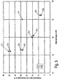
- Fig. 5 shows a graph of product loss in the nozzle phase in% over the wash in m 3 / h.
Landscapes
- Centrifugal Separators (AREA)
- Detail Structures Of Washing Machines And Dryers (AREA)
- Accessory Of Washing/Drying Machine, Commercial Washing/Drying Machine, Other Washing/Drying Machine (AREA)
Description
- Die Erfindung betrifft einen Düsenseparator nach dem Oberbegriff des Anspruchs 1 und ein Verfahren nach dem Oberbegriff des Anspruchs 6.
- In Hinsicht auf den Oberbegriff des Anspruchs 1 wird die
US 4 286 748 A genannt, die eine zentrifugenartige Waschvorrichtung offenbart. Zum technologischen Hintergrund von Sprühvorrichtungen sei ferner dieUS 1 714 232 A angeführt. - Aus dem Stand der Technik sind zudem Verfahren unter dem Begriff "Replacement-Wash" bekannt, bei welchen mit sich radial im Trommelinnenraum nach außen erstreckenden Rezirkulations-Leitungen eine Waschflüssigkeit in den Trommelinnenraum geleitet wird, so dass diese beim Eintritt in den Trommelinnenraum eine radiale und eine axiale Geschwindigkeitskomponente aufweist. Die aus der Mutterlösung abgetrennte Feststoffphase wird durch die Waschlösung aufgenommen und als gewaschene Waschsuspension aus der Trommel über Düsen als Düsenphase aus der Trommel ausgeworfen (
Fig. 2 ). - Dieses Vorgehen hat sich grundsätzlich bewährt, allerdings ergeben sich Vermischungserscheinungen der Waschmittelphase mit der umgebenden feststoffbeladenen Flüssigkeit bzw. Suspension, da die frisch "injizierte" Waschflüssigkeit leichter ist als die umgebende feststoffbeladene Flüssigkeit und deshalb radial nach innen abgelenkt wird.
- Die Erfindung zielt darauf ab, dieses Problem zu verringern.
- Die Erfindung erreicht dieses Ziel durch die Merkmale der Ansprüche 1 und 6.
- Durch den Schritt des Umlenkens der Waschflüssigkeit in Umfangsrichtung und das damit verbundene Aufprägen einer Geschwindigkeitskomponente in Umfangsrichtung werden mehrere vorteilhafte Effekte erzielt, welche das eingangs beschriebene Problem verringern.
- So wird dem radialen Austausch von frischer Waschlösung und Suspension ein erhöhter Widerstand entgegengebracht. Aufgrund der zusätzlichen Umfangsgeschwindigkeit wird die Zentrifugalkraft auf die Waschflüssigkeit vergrößert. Die spezifisch schwerere Flüssigkeit kann die Waschflüssigkeit nicht mehr ganz oder teilweise nach innen verdrängen.
- Durch die Umlenkung des Waschflüssigkeitsstroms in Umfangsrichtung können u.U. Füllkörper und dergleichen an der Innenwandung der Trommel entfallen, was eine konstruktive Vereinfachung der Zentrifuge zur Folge hat und zugleich das nutzbare Trommelvolumen vergrößert.
- Sedimentationen von Feststoffen zwischen den Feststoffaustragsdüsen werden in Richtung dieser Düsen gespült.
- Es ist sogar denkbar, dass auf einen Teil der erforderlichen Feststoffaustragsdüsen verzichtet werden kann, was die Maschinenkosten und die Verstopfungsgefahr verringert.
- Das g-Feld wird durch die zusätzliche Umfangsgeschwindigkeit verstärkt.
- Vorzugsweise liegen die Austrittsöffnungen der Zuleitungsrohre in Umfangsrichtung zwischen den Feststoffaustragsöffnungen, um eine besonders gute Wirkung der vorstehend beschrieben Art zu erzielen. Alternativ können sie aber auch radial in Verlängerung der Austrittsöffnungen liegen.
- Vorteilhafte Ausgestaltungen der Erfindung sind Gegenstand der Unteransprüche.
- Nachfolgend wird in mehreren Ausführungsbeispielen die Erfindung anhand der beigefügten Zeichnungen näher beschrieben. Es zeigen:
-
Fig. 1 einen Schnitt durch einen Abschnitt einer erfindungsgemäßen Zentrifugentrommel senkrecht zur Drehachse; -
Fig. 2 eine zuFig. 1 analoge Ansicht einer bekannten Zentrifugentrommel; -
Fig. 3 eine perspektivische Ansicht eines Abschnitts einer nach Art derFig. 1 aufgebauten Zentrifugentrommel; -
Fig. 4 eine teilgeschnittene Ansicht eines Zulaufrohres; und -
Fig. 5 eine Diagramm, welches einen Produktverlust in % über einer Waschmenge in m3/h veranschaulicht. -
Fig. 2 zeigt einen Schnitt durch ein Unterteil 1 einer als Düsentrommel für einen kontinuierlichen Betrieb ausgelegten Separatortrommel 2 mit vertikaler Drehachse. - Zur Ableitung einer Feststoffphase weist die Separatortrommel 2 im Bereich ihres größten Durchmessers Feststoffaustragsdüsen 3 auf.
- Die Düsentrommel ist mittels eines hier nicht dargestellten Antriebs drehbar und weist neben den in
Fig. 2 dargestellten Komponenten einen Zulauf für eine zu verarbeitende Suspension auf, vorzugsweise ein Tellerpaket aus Trenntellern und eine oder mehrere Einrichtungen zur Ableitung wenigstens einer Flüssigkeitsphase. Derartige Einrichtungen sind dem Fachmann an sich geläufig und bedürfen hier keiner weiteren Erläuterung. - Neben dem Zulauf für die zu verarbeitende Suspension weist die Separatortrommel eine Anordnung 4 zur Zugabe von Waschflüssigkeit in das Trommelinnere auf (siehe zum besseren Verständnis auch
Fig. 3 ). - Diese Anordnung weist einen Zulauf für Waschflüssigkeit (hier nicht zu erkennen) auf, der beispielsweise konzentrisch zum Zulauf(-rohr) für die zu verarbeitende Supension ausgebildet sein kann.
- Der Zulauf für Waschflüssigkeit mündet in einen Verteiler 5 (siehe hierzu auch
Fig. 3 ), der eine Mehrzahl von umfangsverteilten Austrittsöffnungen aufweist, die in sich radial in der Trommel nach außen erstreckende Zuleitungsrohre 6 zur Verteilung und Zuleitung der Waschflüssigkeit in das Trommelinnere münden. - Die Verteilerrohre 6 erstrecken sich nach dem Stand der Technik in der Trommel radial nach außen bis kurz vor die Feststoffaustragsdüsen 3 in der Trommelwand 8. Zwischen benachbarten Feststoffaustragsdüsen 4 sind hier jeweils Wandverstärkungen in Form von Füllkörpern 9 umfangsverteilt angeordnet, die in den Innenraum der Separatortrommel 2 hineinragen und welche aus den Zulaufrohren 1 austretende Waschflüssigkeit in Richtung der Feststoffaustragsdüsen 3 lenken.
- Die Zuleitungsrohre 6 für die Waschflüssigkeit dienen dazu, die Waschflüssigkeit, zumeist eine spezifisch leichtere Waschsäure, in das Trommelinnere in den Bereich kurz vor die Feststoffaustragsdüsen 3 zu leiten.
- Wie bereits einleitend erläutert, kann es neben der zu erwartenden Ablenkung des Strahls der Waschflüssigkeit auch zu einer unerwünscht starken Vermischung mit der in der Separatortrommel 2 enthaltenen Suspension kommen, da die frisch zugegebene Waschflüssigkeit leichter ist als die umgebende, feststoffbeladene Flüssigkeit bzw. die Suspension, so dass die Waschflüssigkeit nach innen abgelenkt wird. Daraus resultiert ein Übertritt der Waschflüssigkeit in den Oberlauf, wodurch die Effektivität der Waschung beeinträchtigt ist.
- Um diesem Effekt entgegenzuwirken, wird vorgeschlagen, wie in
Fig. 1 und3 zu erkennen, die Waschflüssigkeit derart in den Trommelinnenraum zu leiten, dass sie beim Austritt aus dem Zulaufrohr eine Geschwindigkeitskomponente in Umfangsrichtung U - in Umfangsdrehrichtung - aufweist. - Hierzu ist es zweckmäßig, die sich zunächst im Trommelinnenraum radial nach außen erstreckenden Zuleitungsrohre 6 in ihrem radial äußeren Bereich mit einem bogenförmigen Umlenkabschnitt 7 zu versehen, der dazu dient, die Waschflüssigkeit aus der Radialrichtung in Umfangsrichtung U (in Drehrichtung) umzulenken.
- Dieser Umlenkungsabschnitt 7 ist nach
Fig.1 als ein 90°-Rohrbogen ausgebildet, wobei die Austrittsöffnung des Rohrbogens in Umfangsdrehrichtung U gerichtet ist, so dass die Waschflüssigkeit die Umlenkvorrichtung in Drehrichtung U verlässt. - Wie
Fig. 4 zeigt, kann eine Austrittsdüse 10 am Ende jedes Zuleitungsrohres 6 angeordnet sein. - Der Umlenkungswinkel α in Umfangsrichtung U aus der Radialrichtung R beträgt vorzugsweise zwischen 45° und 120° (siehe auch
Fig. 4 ). - Anders als nach
Fig. 2 weist die Separatortrommel 2 an ihrer Innenwand vorzugsweise keine Füllkörper mehr auf, so dass der Innenumfang kreisförmig bzw. zylindrisch ausgebildet ist. - Bei dem Waschverfahren, wird zunächst Waschflüssigkeit, vorzugsweise eine spezifisch leichtere Waschsäure, durch die Zulaufrohre 6 in den Randbereich des Innenraums der Separatortrommel 2 geführt, wo sie in Umfangsrichtung U aus den Zulaufrohren 6 in das Trommelinnere austritt.
-
Fig. 5 zeigt ein Diagramm zum Produktverlust in der Düsenphase in % über der Waschmenge in m3/h. - Die Versuche wurden im Separator DC 130 der Anmelderin durchgeführt. Dabei wurde dem Produktzulauf eine hochkonzentrierte Salzlösung als Tracer beigemischt und anschließend die Salzkonzentration im Oberlauf, bzw. der Greiferphase und Unterlauf, bzw. der Düsenphase, bestimmt. Somit konnte eine vollständige Massenbilanz im Separator durchgeführt werden.
- Dabei wird die bislang bekannte Anordnung zur Zugabe von Waschflüssigkeit (gemäß
Fig.1 ) I und die erfindungsgemäße Anordnung II verglichen, wobei die Messwerte für die bekannte Anordnung durch Rauten I.1-I.3 und die Messwerte für die erfindungsgemäße Anordnung durch Quadrate II1-II6 dargestellt sind. - Bei der bisher bekannten Anordnung zur Zugabe von Waschflüssigkeit (nach
Fig.1 ) wurde das Verhältnis, in dem sich die jeweiligen Mengen auf Ober- und Unterlauf aufteilten, stark von den Dichten der Waschflüssigkeit und des Produktstroms beeinflusst. Diese sind abhängig vom Salzgehalt. Ist die Waschflüssigkeit schwerer als die Produktflüssigkeit, so kommt es bei der bekannten Anordnung zu keiner nennenswerten Vermischung. - Bei der Betrachtung der Messwerte der erfindungsgemäßen Anordnung konnte festgestellt werden, dass der Verlust an flüssigem Produkt, wie er durch die Vermischung der schwereren flüssigen Produktphase mit der leichteren Waschflüssigkeit eintreten kann, bei zunehmender Waschmenge verringert wird.
- Obwohl auch bei der Zugabe der leichteren Waschflüssigkeit in Umfangsrichtung die radiale Vermischung nicht vollständig ausgeschlossen werden konnte, geht weniger an Produkt beim Abführen der Feststoffphase mit der Waschflüssigkeit verloren.
-
Unterteil 1 Separatortrommel 2 Feststoffaustragsdüsen 3 Anordnung 4 Verteiler 5 Zuleitungsrohre 6 Umlenkabschnitt 7 Trommelwand 8 Füllkörper 9 Austrittsdüse 10 Umfangsrichtung U
Claims (6)
- Düsenseparator mit einer vertikalen Drehachse A, mit einer drehbaren Trommel (2) zur Verarbeitung einer zulaufenden Suspension, wobei die Trommel (2) mit einer Anordnung (4) zur Zuleitung von Waschflüssigkeit in den Trommelinnenraum versehen ist, die mehrere Zulaufrohre (6) aufweist, wobei die mehreren Zulaufrohre (6) derart ausgebildet und in der Trommel (2) angeordnet sind, dass die Waschflüssigkeit mit einer Geschwindigkeitskomponente in Umfangsrichtung aus ihnen austritt, dadurch gekennzeichnet, dass die Trommel (2) mit einer Mehrzahl von umfangsverteilten Feststoffaustragsdüsen (3) versehen ist, wobei die Anzahl an Zuleitungsrohren (6) der Anzahl an Feststoffaustragsöffnungen (3) entspricht, und dass die Zuleitungsrohre (6) für Waschflüssigkeit jeweils einen sich in der Trommel radial erstreckenden Abschnitt aufweisen und einen sich daran nach außen anschließenden bogenförmigen Abschnitt (7) zur Umlenkung der Waschflüssigkeit in Umfangsdrehrichtung.
- Düsenseparator nach Anspruch 1, dadurch gekennzeichnet, dass die Zuleitungsrohre (6) jeweils eine Austrittsöffnung aufweisen, die mit einer Austrittsdüse (10) versehen ist.
- Düsenseparator nach einem der vorstehenden Ansprüche, dadurch gekennzeichnet, dass zwischen in Umfangsrichtung benachbarten Feststoffaustrittsdüsen (3) keine Füllkörper an der Trommelinnenwand ausgebildet sind.
- Düsenseparator nach einem der vorstehenden Ansprüche, dadurch gekennzeichnet, dass die Austrittsöffnungen der Zuleitungsrohre (6) in Umfangsrichtung zwischen den Feststoffaustragsöffnungen (3) liegen.
- Düsenseparator nach einem der vorstehenden Ansprüche, dadurch gekennzeichnet, dass die Austrittsöffnungen der Zuleitungsrohre (6) in Umfangsrichtung jeweils mittig zwischen zueinander benachbarten Feststoffaustragsöffnungen (3) liegen.
- Verfahren zum Ableiten einer Feststoffphase aus einer Düsenseparator, die nach einem der vorstehenden Ansprüche ausgebildet ist, dadurch gekennzeichnet, dass die Waschflüssigkeit mit einer Geschwindigkeitskomponente in Umfangsrichtung (U) in den Trommelinnenraum geleitet wird
Priority Applications (1)
| Application Number | Priority Date | Filing Date | Title |
|---|---|---|---|
| PL11715533T PL2566626T5 (pl) | 2010-05-03 | 2011-04-19 | Separator dyszowy i sposób odprowadzania fazy stałej z separatora dyszowego |
Applications Claiming Priority (2)
| Application Number | Priority Date | Filing Date | Title |
|---|---|---|---|
| DE102010016740.1A DE102010016740B4 (de) | 2010-05-03 | 2010-05-03 | Düsenseparator und Verfahren zum Ableiten einer Feststoffphase aus dem Düsenseparator |
| PCT/EP2011/056275 WO2011138167A1 (de) | 2010-05-03 | 2011-04-19 | Düsenseparator und verfahren zum ableiten einer feststoffphase aus dem düsenseparator |
Publications (3)
| Publication Number | Publication Date |
|---|---|
| EP2566626A1 EP2566626A1 (de) | 2013-03-13 |
| EP2566626B1 EP2566626B1 (de) | 2014-03-19 |
| EP2566626B2 true EP2566626B2 (de) | 2017-10-25 |
Family
ID=44275665
Family Applications (1)
| Application Number | Title | Priority Date | Filing Date |
|---|---|---|---|
| EP11715533.3A Active EP2566626B2 (de) | 2010-05-03 | 2011-04-19 | Düsenseparator und verfahren zum ableiten einer feststoffphase aus dem düsenseparator |
Country Status (9)
| Country | Link |
|---|---|
| US (1) | US8753254B2 (de) |
| EP (1) | EP2566626B2 (de) |
| KR (1) | KR101761119B1 (de) |
| CN (1) | CN102858463B (de) |
| BR (1) | BR112012027879B1 (de) |
| DE (1) | DE102010016740B4 (de) |
| DK (1) | DK2566626T4 (de) |
| PL (1) | PL2566626T5 (de) |
| WO (1) | WO2011138167A1 (de) |
Families Citing this family (1)
| Publication number | Priority date | Publication date | Assignee | Title |
|---|---|---|---|---|
| DE102010016740B4 (de) * | 2010-05-03 | 2021-02-18 | Gea Mechanical Equipment Gmbh | Düsenseparator und Verfahren zum Ableiten einer Feststoffphase aus dem Düsenseparator |
Citations (7)
| Publication number | Priority date | Publication date | Assignee | Title |
|---|---|---|---|---|
| US1847751A (en) † | 1930-03-31 | 1932-03-01 | Merco Centrifugal Separator Co | Centrifuge method and apparatus |
| US1886111A (en) † | 1930-11-25 | 1932-11-01 | Laurits I Lorentsen | Centrifugal mineral separator |
| US1926402A (en) † | 1930-10-27 | 1933-09-12 | Railway Service & Supply Corp | Extractor |
| EP0486260A2 (de) † | 1990-11-13 | 1992-05-20 | Dorr-Oliver Incorporated | Hochleistungswaschzentrifuge |
| US5403486A (en) † | 1991-12-31 | 1995-04-04 | Baker Hughes Incorporated | Accelerator system in a centrifuge |
| WO2002076621A1 (en) † | 2001-03-23 | 2002-10-03 | Aventis Pharma Deutschland Gmbh | Horizontal solid-bowl centrifuge with cleaning-in-place nozzles |
| US20050192173A1 (en) † | 2004-02-07 | 2005-09-01 | Thomas Broadbent & Sons Limited | Washing of separated solids in solid bowl and screen bowl decanting centrifuges |
Family Cites Families (16)
| Publication number | Priority date | Publication date | Assignee | Title |
|---|---|---|---|---|
| US1714232A (en) * | 1923-03-22 | 1929-05-21 | Cresson Morris Company | Spraying device |
| US2518436A (en) * | 1947-12-30 | 1950-08-08 | Laval Separator Co De | Flushing assembly for centrifugal separators |
| US2612314A (en) * | 1949-03-28 | 1952-09-30 | Lewis L Huelsdonk | Centrifuge |
| DE1120261B (de) * | 1958-06-28 | 1961-12-21 | Doerries A G O | Schleuder zum Reinigen von Faserstoffaufschwemmungen |
| US3302873A (en) * | 1964-02-21 | 1967-02-07 | Pennsalt Chemicals Corp | Centrifugal solids deliquefying and treating process and apparatus |
| US4299352A (en) * | 1979-03-23 | 1981-11-10 | Kobe, Inc. | Centrifuge apparatus |
| US4286748A (en) * | 1980-05-19 | 1981-09-01 | Bailey Albert C | Centrifugal concentrator |
| US4406651A (en) * | 1982-04-15 | 1983-09-27 | Donaldson Company, Inc. | Multi-phase self purging centrifuge |
| GB2121325A (en) * | 1982-06-07 | 1983-12-21 | Fsp | Cleaning centrifuge |
| JPS5932967A (ja) * | 1982-08-16 | 1984-02-22 | Toshiba Corp | 遠心清澄機 |
| GB8517762D0 (en) * | 1985-07-15 | 1985-08-21 | British Nuclear Fuels Plc | Centrifuges |
| US4846780A (en) * | 1988-08-10 | 1989-07-11 | Exxon Production Research Company | Centrifuge processor and liquid level control system |
| CA2131738C (en) * | 1993-11-17 | 2001-09-04 | Lonny R. Kelley | Flow enhanced one-pass centrifuge separator |
| US5908376A (en) * | 1997-09-11 | 1999-06-01 | Costner Industries Nevada, Inc. | Self-cleaning rotor for a centrifugal separator |
| CN2390698Y (zh) * | 1999-08-25 | 2000-08-09 | 邵国柱 | 变频型碟式分离机 |
| DE102010016740B4 (de) * | 2010-05-03 | 2021-02-18 | Gea Mechanical Equipment Gmbh | Düsenseparator und Verfahren zum Ableiten einer Feststoffphase aus dem Düsenseparator |
-
2010
- 2010-05-03 DE DE102010016740.1A patent/DE102010016740B4/de active Active
-
2011
- 2011-04-19 PL PL11715533T patent/PL2566626T5/pl unknown
- 2011-04-19 KR KR1020127031503A patent/KR101761119B1/ko active IP Right Grant
- 2011-04-19 WO PCT/EP2011/056275 patent/WO2011138167A1/de active Application Filing
- 2011-04-19 US US13/642,037 patent/US8753254B2/en active Active
- 2011-04-19 BR BR112012027879-7A patent/BR112012027879B1/pt active IP Right Grant
- 2011-04-19 CN CN201180021668.9A patent/CN102858463B/zh active Active
- 2011-04-19 DK DK11715533.3T patent/DK2566626T4/en active
- 2011-04-19 EP EP11715533.3A patent/EP2566626B2/de active Active
Patent Citations (7)
| Publication number | Priority date | Publication date | Assignee | Title |
|---|---|---|---|---|
| US1847751A (en) † | 1930-03-31 | 1932-03-01 | Merco Centrifugal Separator Co | Centrifuge method and apparatus |
| US1926402A (en) † | 1930-10-27 | 1933-09-12 | Railway Service & Supply Corp | Extractor |
| US1886111A (en) † | 1930-11-25 | 1932-11-01 | Laurits I Lorentsen | Centrifugal mineral separator |
| EP0486260A2 (de) † | 1990-11-13 | 1992-05-20 | Dorr-Oliver Incorporated | Hochleistungswaschzentrifuge |
| US5403486A (en) † | 1991-12-31 | 1995-04-04 | Baker Hughes Incorporated | Accelerator system in a centrifuge |
| WO2002076621A1 (en) † | 2001-03-23 | 2002-10-03 | Aventis Pharma Deutschland Gmbh | Horizontal solid-bowl centrifuge with cleaning-in-place nozzles |
| US20050192173A1 (en) † | 2004-02-07 | 2005-09-01 | Thomas Broadbent & Sons Limited | Washing of separated solids in solid bowl and screen bowl decanting centrifuges |
Also Published As
| Publication number | Publication date |
|---|---|
| DE102010016740B4 (de) | 2021-02-18 |
| DE102010016740A1 (de) | 2011-11-03 |
| WO2011138167A1 (de) | 2011-11-10 |
| BR112012027879A2 (pt) | 2017-09-26 |
| US20130053231A1 (en) | 2013-02-28 |
| EP2566626B1 (de) | 2014-03-19 |
| CN102858463A (zh) | 2013-01-02 |
| CN102858463B (zh) | 2015-04-01 |
| KR20130053412A (ko) | 2013-05-23 |
| BR112012027879B1 (pt) | 2020-10-13 |
| US8753254B2 (en) | 2014-06-17 |
| PL2566626T3 (pl) | 2014-08-29 |
| EP2566626A1 (de) | 2013-03-13 |
| DK2566626T4 (en) | 2018-01-15 |
| KR101761119B1 (ko) | 2017-07-25 |
| DK2566626T3 (da) | 2014-06-16 |
| PL2566626T5 (pl) | 2018-04-30 |
Similar Documents
| Publication | Publication Date | Title |
|---|---|---|
| EP2512684B1 (de) | Abscheidevorrichtung mit einem gravitationsvorabscheider gefolgt von einem zentrifugalabscheider | |
| EP2598251B1 (de) | Vollmantel-schneckenzentrifuge mit überlaufwehr | |
| EP0541759B1 (de) | Fliessbettapparatur zum behandeln partikelförmigen gutes | |
| WO2012013654A2 (de) | Separator mit einer schleudertrommel | |
| EP2321056B1 (de) | Separatortrommel mit verteiler | |
| EP4096836A1 (de) | Verfahren zum hochgeschwindigkeitsbeschichten der innenfläche eines rohlings | |
| EP2566626B2 (de) | Düsenseparator und verfahren zum ableiten einer feststoffphase aus dem düsenseparator | |
| DE2542236C2 (de) | Dünnschichtapparat | |
| DE102006011452B4 (de) | Zentrifuge mit einem Einlaufrohr | |
| EP2910355B1 (de) | Vorrichtung zum Waschen von Schüttgut | |
| EP0430985B1 (de) | Vorrichtung zur aufbereitung flüssiger bis dünnbreiiger medien | |
| WO2012163511A2 (de) | Rotierende sprühvorrichtung | |
| EP0163112B1 (de) | Verfahren und Vorrichtung zum Trennschleudern von Feinkornmineralgemischen | |
| DE3910349A1 (de) | Papiermaterial-aufbereitungsvorrichtung | |
| DE102009021588B4 (de) | Kontinuierlich arbeitende Zentrifuge | |
| DE10247646B4 (de) | Zentrifuge mit Not-Aus-System | |
| EP3320976B1 (de) | Einlaufvorrichtung für eine dekanterzentrifuge | |
| DE202010005476U1 (de) | Separator | |
| EP2146167B1 (de) | Vorrichtung und Verfahren zum Entfernen von Fluiden | |
| EP4249100A1 (de) | Druckbandfilter | |
| EP2586514B1 (de) | Sausystem mit Filtereinheit | |
| WO2007144339A1 (de) | Zentrifuge, insbesondere separator, mit einer zuleitung für steuerfluid | |
| DE1008660B (de) | Zentrifuge mit einer sieblosen Trommel und Austrittduesen fuer den Ablauf der schweren Bestandteile | |
| DE1252635B (de) | ||
| DE102007003071A1 (de) | Verfahren zur Phasentrennung eines Produktes mit einer Zentrifuge und Separator |
Legal Events
| Date | Code | Title | Description |
|---|---|---|---|
| PUAI | Public reference made under article 153(3) epc to a published international application that has entered the european phase |
Free format text: ORIGINAL CODE: 0009012 |
|
| 17P | Request for examination filed |
Effective date: 20121112 |
|
| AK | Designated contracting states |
Kind code of ref document: A1 Designated state(s): AL AT BE BG CH CY CZ DE DK EE ES FI FR GB GR HR HU IE IS IT LI LT LU LV MC MK MT NL NO PL PT RO RS SE SI SK SM TR |
|
| DAX | Request for extension of the european patent (deleted) | ||
| GRAP | Despatch of communication of intention to grant a patent |
Free format text: ORIGINAL CODE: EPIDOSNIGR1 |
|
| INTG | Intention to grant announced |
Effective date: 20131129 |
|
| GRAS | Grant fee paid |
Free format text: ORIGINAL CODE: EPIDOSNIGR3 |
|
| GRAA | (expected) grant |
Free format text: ORIGINAL CODE: 0009210 |
|
| AK | Designated contracting states |
Kind code of ref document: B1 Designated state(s): AL AT BE BG CH CY CZ DE DK EE ES FI FR GB GR HR HU IE IS IT LI LT LU LV MC MK MT NL NO PL PT RO RS SE SI SK SM TR |
|
| REG | Reference to a national code |
Ref country code: GB Ref legal event code: FG4D Free format text: NOT ENGLISH |
|
| REG | Reference to a national code |
Ref country code: CH Ref legal event code: EP |
|
| REG | Reference to a national code |
Ref country code: AT Ref legal event code: REF Ref document number: 657287 Country of ref document: AT Kind code of ref document: T Effective date: 20140415 |
|
| REG | Reference to a national code |
Ref country code: IE Ref legal event code: FG4D Free format text: LANGUAGE OF EP DOCUMENT: GERMAN |
|
| REG | Reference to a national code |
Ref country code: DE Ref legal event code: R096 Ref document number: 502011002468 Country of ref document: DE Effective date: 20140430 Ref country code: NL Ref legal event code: T3 |
|
| REG | Reference to a national code |
Ref country code: DK Ref legal event code: T3 Effective date: 20140612 |
|
| PG25 | Lapsed in a contracting state [announced via postgrant information from national office to epo] |
Ref country code: LT Free format text: LAPSE BECAUSE OF FAILURE TO SUBMIT A TRANSLATION OF THE DESCRIPTION OR TO PAY THE FEE WITHIN THE PRESCRIBED TIME-LIMIT Effective date: 20140319 Ref country code: NO Free format text: LAPSE BECAUSE OF FAILURE TO SUBMIT A TRANSLATION OF THE DESCRIPTION OR TO PAY THE FEE WITHIN THE PRESCRIBED TIME-LIMIT Effective date: 20140619 |
|
| REG | Reference to a national code |
Ref country code: LT Ref legal event code: MG4D |
|
| PG25 | Lapsed in a contracting state [announced via postgrant information from national office to epo] |
Ref country code: CY Free format text: LAPSE BECAUSE OF FAILURE TO SUBMIT A TRANSLATION OF THE DESCRIPTION OR TO PAY THE FEE WITHIN THE PRESCRIBED TIME-LIMIT Effective date: 20140319 Ref country code: SE Free format text: LAPSE BECAUSE OF FAILURE TO SUBMIT A TRANSLATION OF THE DESCRIPTION OR TO PAY THE FEE WITHIN THE PRESCRIBED TIME-LIMIT Effective date: 20140319 Ref country code: FI Free format text: LAPSE BECAUSE OF FAILURE TO SUBMIT A TRANSLATION OF THE DESCRIPTION OR TO PAY THE FEE WITHIN THE PRESCRIBED TIME-LIMIT Effective date: 20140319 |
|
| REG | Reference to a national code |
Ref country code: PL Ref legal event code: T3 |
|
| PG25 | Lapsed in a contracting state [announced via postgrant information from national office to epo] |
Ref country code: HR Free format text: LAPSE BECAUSE OF FAILURE TO SUBMIT A TRANSLATION OF THE DESCRIPTION OR TO PAY THE FEE WITHIN THE PRESCRIBED TIME-LIMIT Effective date: 20140319 Ref country code: LV Free format text: LAPSE BECAUSE OF FAILURE TO SUBMIT A TRANSLATION OF THE DESCRIPTION OR TO PAY THE FEE WITHIN THE PRESCRIBED TIME-LIMIT Effective date: 20140319 Ref country code: RS Free format text: LAPSE BECAUSE OF FAILURE TO SUBMIT A TRANSLATION OF THE DESCRIPTION OR TO PAY THE FEE WITHIN THE PRESCRIBED TIME-LIMIT Effective date: 20140319 |
|
| PG25 | Lapsed in a contracting state [announced via postgrant information from national office to epo] |
Ref country code: IS Free format text: LAPSE BECAUSE OF FAILURE TO SUBMIT A TRANSLATION OF THE DESCRIPTION OR TO PAY THE FEE WITHIN THE PRESCRIBED TIME-LIMIT Effective date: 20140719 Ref country code: RO Free format text: LAPSE BECAUSE OF FAILURE TO SUBMIT A TRANSLATION OF THE DESCRIPTION OR TO PAY THE FEE WITHIN THE PRESCRIBED TIME-LIMIT Effective date: 20140319 Ref country code: CZ Free format text: LAPSE BECAUSE OF FAILURE TO SUBMIT A TRANSLATION OF THE DESCRIPTION OR TO PAY THE FEE WITHIN THE PRESCRIBED TIME-LIMIT Effective date: 20140319 Ref country code: BG Free format text: LAPSE BECAUSE OF FAILURE TO SUBMIT A TRANSLATION OF THE DESCRIPTION OR TO PAY THE FEE WITHIN THE PRESCRIBED TIME-LIMIT Effective date: 20140619 Ref country code: EE Free format text: LAPSE BECAUSE OF FAILURE TO SUBMIT A TRANSLATION OF THE DESCRIPTION OR TO PAY THE FEE WITHIN THE PRESCRIBED TIME-LIMIT Effective date: 20140319 |
|
| PG25 | Lapsed in a contracting state [announced via postgrant information from national office to epo] |
Ref country code: SK Free format text: LAPSE BECAUSE OF FAILURE TO SUBMIT A TRANSLATION OF THE DESCRIPTION OR TO PAY THE FEE WITHIN THE PRESCRIBED TIME-LIMIT Effective date: 20140319 Ref country code: MC Free format text: LAPSE BECAUSE OF FAILURE TO SUBMIT A TRANSLATION OF THE DESCRIPTION OR TO PAY THE FEE WITHIN THE PRESCRIBED TIME-LIMIT Effective date: 20140319 Ref country code: ES Free format text: LAPSE BECAUSE OF FAILURE TO SUBMIT A TRANSLATION OF THE DESCRIPTION OR TO PAY THE FEE WITHIN THE PRESCRIBED TIME-LIMIT Effective date: 20140319 |
|
| REG | Reference to a national code |
Ref country code: CH Ref legal event code: PL |
|
| REG | Reference to a national code |
Ref country code: DE Ref legal event code: R026 Ref document number: 502011002468 Country of ref document: DE |
|
| PLBI | Opposition filed |
Free format text: ORIGINAL CODE: 0009260 |
|
| PG25 | Lapsed in a contracting state [announced via postgrant information from national office to epo] |
Ref country code: PT Free format text: LAPSE BECAUSE OF FAILURE TO SUBMIT A TRANSLATION OF THE DESCRIPTION OR TO PAY THE FEE WITHIN THE PRESCRIBED TIME-LIMIT Effective date: 20140721 |
|
| 26 | Opposition filed |
Opponent name: ALFA LAVAL CORPORATE AB Effective date: 20141216 |
|
| PLAX | Notice of opposition and request to file observation + time limit sent |
Free format text: ORIGINAL CODE: EPIDOSNOBS2 |
|
| REG | Reference to a national code |
Ref country code: IE Ref legal event code: MM4A |
|
| PG25 | Lapsed in a contracting state [announced via postgrant information from national office to epo] |
Ref country code: CH Free format text: LAPSE BECAUSE OF NON-PAYMENT OF DUE FEES Effective date: 20140430 Ref country code: LI Free format text: LAPSE BECAUSE OF NON-PAYMENT OF DUE FEES Effective date: 20140430 |
|
| REG | Reference to a national code |
Ref country code: DE Ref legal event code: R026 Ref document number: 502011002468 Country of ref document: DE Effective date: 20141216 |
|
| PG25 | Lapsed in a contracting state [announced via postgrant information from national office to epo] |
Ref country code: IT Free format text: LAPSE BECAUSE OF FAILURE TO SUBMIT A TRANSLATION OF THE DESCRIPTION OR TO PAY THE FEE WITHIN THE PRESCRIBED TIME-LIMIT Effective date: 20140319 |
|
| PG25 | Lapsed in a contracting state [announced via postgrant information from national office to epo] |
Ref country code: IE Free format text: LAPSE BECAUSE OF NON-PAYMENT OF DUE FEES Effective date: 20140419 |
|
| PLAF | Information modified related to communication of a notice of opposition and request to file observations + time limit |
Free format text: ORIGINAL CODE: EPIDOSCOBS2 |
|
| PLBB | Reply of patent proprietor to notice(s) of opposition received |
Free format text: ORIGINAL CODE: EPIDOSNOBS3 |
|
| PG25 | Lapsed in a contracting state [announced via postgrant information from national office to epo] |
Ref country code: SI Free format text: LAPSE BECAUSE OF FAILURE TO SUBMIT A TRANSLATION OF THE DESCRIPTION OR TO PAY THE FEE WITHIN THE PRESCRIBED TIME-LIMIT Effective date: 20140319 |
|
| PG25 | Lapsed in a contracting state [announced via postgrant information from national office to epo] |
Ref country code: MT Free format text: LAPSE BECAUSE OF FAILURE TO SUBMIT A TRANSLATION OF THE DESCRIPTION OR TO PAY THE FEE WITHIN THE PRESCRIBED TIME-LIMIT Effective date: 20140319 |
|
| REG | Reference to a national code |
Ref country code: FR Ref legal event code: PLFP Year of fee payment: 6 |
|
| PG25 | Lapsed in a contracting state [announced via postgrant information from national office to epo] |
Ref country code: SM Free format text: LAPSE BECAUSE OF FAILURE TO SUBMIT A TRANSLATION OF THE DESCRIPTION OR TO PAY THE FEE WITHIN THE PRESCRIBED TIME-LIMIT Effective date: 20140319 |
|
| PG25 | Lapsed in a contracting state [announced via postgrant information from national office to epo] |
Ref country code: GR Free format text: LAPSE BECAUSE OF FAILURE TO SUBMIT A TRANSLATION OF THE DESCRIPTION OR TO PAY THE FEE WITHIN THE PRESCRIBED TIME-LIMIT Effective date: 20140620 |
|
| PG25 | Lapsed in a contracting state [announced via postgrant information from national office to epo] |
Ref country code: HU Free format text: LAPSE BECAUSE OF FAILURE TO SUBMIT A TRANSLATION OF THE DESCRIPTION OR TO PAY THE FEE WITHIN THE PRESCRIBED TIME-LIMIT; INVALID AB INITIO Effective date: 20110419 Ref country code: LU Free format text: LAPSE BECAUSE OF NON-PAYMENT OF DUE FEES Effective date: 20140419 |
|
| REG | Reference to a national code |
Ref country code: FR Ref legal event code: PLFP Year of fee payment: 7 |
|
| RIC2 | Information provided on ipc code assigned after grant |
Ipc: B04B 1/10 20060101AFI20170602BHEP Ipc: B04B 15/12 20060101ALI20170602BHEP |
|
| PUAH | Patent maintained in amended form |
Free format text: ORIGINAL CODE: 0009272 |
|
| STAA | Information on the status of an ep patent application or granted ep patent |
Free format text: STATUS: PATENT MAINTAINED AS AMENDED |
|
| 27A | Patent maintained in amended form |
Effective date: 20171025 |
|
| AK | Designated contracting states |
Kind code of ref document: B2 Designated state(s): AL AT BE BG CH CY CZ DE DK EE ES FI FR GB GR HR HU IE IS IT LI LT LU LV MC MK MT NL NO PL PT RO RS SE SI SK SM TR |
|
| REG | Reference to a national code |
Ref country code: DE Ref legal event code: R102 Ref document number: 502011002468 Country of ref document: DE |
|
| REG | Reference to a national code |
Ref country code: DK Ref legal event code: T4 Effective date: 20180111 |
|
| REG | Reference to a national code |
Ref country code: NL Ref legal event code: FP |
|
| REG | Reference to a national code |
Ref country code: FR Ref legal event code: PLFP Year of fee payment: 8 |
|
| PG25 | Lapsed in a contracting state [announced via postgrant information from national office to epo] |
Ref country code: LV Free format text: LAPSE BECAUSE OF FAILURE TO SUBMIT A TRANSLATION OF THE DESCRIPTION OR TO PAY THE FEE WITHIN THE PRESCRIBED TIME-LIMIT Effective date: 20140319 |
|
| PG25 | Lapsed in a contracting state [announced via postgrant information from national office to epo] |
Ref country code: MK Free format text: LAPSE BECAUSE OF FAILURE TO SUBMIT A TRANSLATION OF THE DESCRIPTION OR TO PAY THE FEE WITHIN THE PRESCRIBED TIME-LIMIT Effective date: 20140319 |
|
| PG25 | Lapsed in a contracting state [announced via postgrant information from national office to epo] |
Ref country code: AL Free format text: LAPSE BECAUSE OF FAILURE TO SUBMIT A TRANSLATION OF THE DESCRIPTION OR TO PAY THE FEE WITHIN THE PRESCRIBED TIME-LIMIT Effective date: 20140319 |
|
| PGFP | Annual fee paid to national office [announced via postgrant information from national office to epo] |
Ref country code: PL Payment date: 20230324 Year of fee payment: 13 |
|
| P01 | Opt-out of the competence of the unified patent court (upc) registered |
Effective date: 20230402 |
|
| PGFP | Annual fee paid to national office [announced via postgrant information from national office to epo] |
Ref country code: FR Payment date: 20230425 Year of fee payment: 13 Ref country code: DK Payment date: 20230420 Year of fee payment: 13 Ref country code: DE Payment date: 20230426 Year of fee payment: 13 |
|
| PGFP | Annual fee paid to national office [announced via postgrant information from national office to epo] |
Ref country code: TR Payment date: 20230412 Year of fee payment: 13 Ref country code: AT Payment date: 20230426 Year of fee payment: 13 |
|
| PGFP | Annual fee paid to national office [announced via postgrant information from national office to epo] |
Ref country code: BE Payment date: 20230420 Year of fee payment: 13 |
|
| PGFP | Annual fee paid to national office [announced via postgrant information from national office to epo] |
Ref country code: GB Payment date: 20230420 Year of fee payment: 13 |
|
| PGFP | Annual fee paid to national office [announced via postgrant information from national office to epo] |
Ref country code: NL Payment date: 20240425 Year of fee payment: 14 |