EP2315065B1 - Mikroskop - Google Patents
Mikroskop Download PDFInfo
- Publication number
- EP2315065B1 EP2315065B1 EP20100013563 EP10013563A EP2315065B1 EP 2315065 B1 EP2315065 B1 EP 2315065B1 EP 20100013563 EP20100013563 EP 20100013563 EP 10013563 A EP10013563 A EP 10013563A EP 2315065 B1 EP2315065 B1 EP 2315065B1
- Authority
- EP
- European Patent Office
- Prior art keywords
- light
- incoherent light
- microscope
- incoherent
- specimen
- Prior art date
- Legal status (The legal status is an assumption and is not a legal conclusion. Google has not performed a legal analysis and makes no representation as to the accuracy of the status listed.)
- Not-in-force
Links
- 238000005286 illumination Methods 0.000 claims description 84
- 230000003287 optical effect Effects 0.000 claims description 67
- 230000007246 mechanism Effects 0.000 claims description 38
- 239000013307 optical fiber Substances 0.000 claims description 26
- 239000000835 fiber Substances 0.000 claims description 11
- 239000010453 quartz Substances 0.000 claims description 8
- VYPSYNLAJGMNEJ-UHFFFAOYSA-N silicon dioxide Inorganic materials O=[Si]=O VYPSYNLAJGMNEJ-UHFFFAOYSA-N 0.000 claims description 8
- 230000008859 change Effects 0.000 claims description 3
- 230000004048 modification Effects 0.000 description 30
- 238000012986 modification Methods 0.000 description 30
- 230000005284 excitation Effects 0.000 description 11
- 230000001678 irradiating effect Effects 0.000 description 11
- 238000001514 detection method Methods 0.000 description 8
- 238000010586 diagram Methods 0.000 description 6
- 241000276498 Pollachius virens Species 0.000 description 5
- 230000004888 barrier function Effects 0.000 description 5
- 230000003247 decreasing effect Effects 0.000 description 5
- 230000004936 stimulating effect Effects 0.000 description 5
- 238000003384 imaging method Methods 0.000 description 4
- 230000001427 coherent effect Effects 0.000 description 3
- 238000002073 fluorescence micrograph Methods 0.000 description 3
- 239000000126 substance Substances 0.000 description 3
- 238000002834 transmittance Methods 0.000 description 3
- 230000005540 biological transmission Effects 0.000 description 2
- 230000015556 catabolic process Effects 0.000 description 2
- 238000006731 degradation reaction Methods 0.000 description 2
- 239000000428 dust Substances 0.000 description 2
- 239000004973 liquid crystal related substance Substances 0.000 description 2
- QSHDDOUJBYECFT-UHFFFAOYSA-N mercury Chemical compound [Hg] QSHDDOUJBYECFT-UHFFFAOYSA-N 0.000 description 2
- 229910052753 mercury Inorganic materials 0.000 description 2
- 230000002093 peripheral effect Effects 0.000 description 2
- 230000008901 benefit Effects 0.000 description 1
- 230000000694 effects Effects 0.000 description 1
- 229910052736 halogen Inorganic materials 0.000 description 1
- 150000002367 halogens Chemical class 0.000 description 1
- 238000004519 manufacturing process Methods 0.000 description 1
Images


Classifications
-
- G—PHYSICS
- G02—OPTICS
- G02B—OPTICAL ELEMENTS, SYSTEMS OR APPARATUS
- G02B21/00—Microscopes
- G02B21/06—Means for illuminating specimens
- G02B21/08—Condensers
- G02B21/088—Condensers for both incident illumination and transillumination
-
- G—PHYSICS
- G02—OPTICS
- G02B—OPTICAL ELEMENTS, SYSTEMS OR APPARATUS
- G02B21/00—Microscopes
- G02B21/06—Means for illuminating specimens
-
- G—PHYSICS
- G02—OPTICS
- G02B—OPTICAL ELEMENTS, SYSTEMS OR APPARATUS
- G02B21/00—Microscopes
- G02B21/16—Microscopes adapted for ultraviolet illumination ; Fluorescence microscopes
-
- G—PHYSICS
- G02—OPTICS
- G02B—OPTICAL ELEMENTS, SYSTEMS OR APPARATUS
- G02B21/00—Microscopes
- G02B21/32—Micromanipulators structurally combined with microscopes
Definitions
- the present invention relates to microscopes.
- a known microscope that includes a light source for irradiating a specimen with coherent light or incoherent light, a photodetector for detecting fluorescence coming from the specimen, and a digital micromirror device (hereinafter referred to as "DMD") disposed between the light source and the photodetector and having a plurality of micromirrors (see, for example, the Publication of Japanese Patent No. 3634343 , the Publication of Japanese Patent No. 4084303 , and Japanese Unexamined Patent Application, Publication No. 2004-109348 ).
- DMD digital micromirror device
- Document US 2003/0086145 A1 concerns a spatial light modulator apparatus for an optical microscope system including an optical head with a mounting flange for mounting the optical head to a port of the microscope, a DMD for generating a pattern image of light, a light source mount for receiving a source of illumination, and one or more optical elements for directing light from the source of illumination to the DMD and to direct the pattern image generated by the DMD to the microscope.
- a microscope disclosed in the Publication of Japanese Patent No. 3634343 causes coherent light (laser light) to be incident on a DMD to form a pattern to be projected on a specimen with the DMD before projecting the light on the specimen.
- this microscope has a problem in that the DMD diffracts the coherent light incident thereon, thus leaving unevenness in the intensity of the illumination light.
- a microscope disclosed in the Publication of Japanese Patent No. 4084303 generates a pattern image of light with a DMD and directs it to the microscope, and the light source used is a halogen light source, an arc light source, or a laser light source.
- this microscope has a problem in that it has no element for allowing the illumination to be incident on the DMD in a uniform state and cannot therefore make the incoherent light uniform, thus leaving unevenness in the intensity of the illumination light.
- a microscope disclosed in Japanese Unexamined Patent Application, Publication No. 2004-109348 has a diffuser between a white light source and a DMD to reduce unevenness in the intensity of illumination light.
- this microscope has a problem in that the amount of light is decreased depending on the transmittance of the diffuser.
- An object of the present invention which has been made in light of the circumstances described above, is to provide a microscope that allows irradiation with uniform illumination light without decreasing the amount of light.
- the present invention employs the solution as defined in claim 1.
- the present invention employs a microscope including an incoherent light source that emits incoherent light; a light-guiding member on which the incoherent light coming from the incoherent light source is incident and which guides the incident incoherent light by repeated total reflection; a microdevice array having an array of microdevices each reflecting or transmitting the incoherent light guided by the light-guiding member; a pattern illumination optical system that irradiates a specimen with the incoherent light reflected or transmitted by the microdevice array; an objective lens that collects light coming from the specimen; and a photodetector that is disposed at a position conjugate to the position of the microdevice array and that detects the light coming from the specimen and collected by the objective lens.
- the incoherent light emitted from the incoherent light source is incident on the light-guiding member and is made uniform in the light-guiding member by repeated total reflection.
- the uniform incoherent light is reflected or transmitted by the microdevices of the microdevice array, and the specimen is irradiated therewith by the objective lens.
- a fluorescent substance present in the specimen is excited to emit fluorescence, and the emitted fluorescence is collected by the objective lens and is detected by the photodetector.
- the microdevices for reflection or transmission on the microdevice array can be switched to vary the region irradiated with the incoherent light on the specimen, thus obtaining an image of the specimen in any region.
- the incoherent light with which the specimen is irradiated is made uniform by the light-guiding member.
- the specimen can be irradiated with uniform incoherent light without decreasing the amount of light, thus obtaining an image without unevenness.
- the pattern illumination optical system may include the objective lens, and the microscope may further include a splitting section that splits off the light coming from the specimen and collected by the objective lens from the incoherent light and that directs the light to the photodetector.
- the pattern illumination optical system may include a condenser lens disposed opposite the objective lens with the specimen therebetween.
- the light-guiding member may be a quartz fiber.
- the light-guiding member is a quartz fiber, the incoherent light can be guided while being efficiently made uniform.
- a quartz fiber is suitable as the light-guiding member because it has high transmittance for visible light (400 to 600 nm).
- the microscope further includes an irradiation optical system that irradiates the microdevice array with the incoherent light guided by the light-guiding member, and the irradiation optical system may project an exit surface of the light-guiding member onto the microdevice array.
- the incoherent light can be efficiently made uniform.
- the irradiation optical system is a critical optical system, the specimen can be irradiated with uniform incoherent light while ensuring incoherence.
- the irradiation optical system may irradiate a region larger than a region where the microdevices of the microdevice array are arranged with the incoherent light guided by the light-guiding member.
- the overfill level may be set such that uneven illumination can be compensated for at the end surface of the light-guiding member, and is preferably set such that, for example, a region about 1.2 times the area of the examination field is illuminated.
- the microscope further includes a zoom mechanism that is disposed between the light-guiding member and the microdevice array and that changes the focal distance of the incoherent light.
- the focal distance of the incoherent light can be changed to change the area of the region irradiated with the incoherent light on the microdevice array. Accordingly, for example, the incoherent light can be collected in a particular region (for example, near the center of the microdevice array) to more intensely illuminate the center of the field of view, thus obtaining a brighter image.
- the microscope may further include a shift mechanism that is disposed between the zoom mechanism and the microdevice array and that shifts the incoherent light in a direction perpendicular to an optical axis thereof.
- the incoherent light can be shifted in a direction perpendicular to the optical axis to shift the irradiation region collected by the zoom mechanism to any region (for example, the peripheral region of the field of view). This allows any region to be intensely irradiated with the incoherent light, thus obtaining a bright image in that region.
- the incoherent light source may be independently provided, and the microscope may further include an optical fiber between the incoherent light source and the microdevice array.
- the incoherent light source acting as a source of heat and vibration, can be separated from the main body of the microscope, thus improving the stability of illumination.
- the microscope may further include an illumination light source that emits illumination light having a wavelength band different from that of the incoherent light and a combining section that is disposed between the microdevice array and the objective lens and that combines the illumination light coming from the illumination light source and the incoherent light coming from the incoherent light source.
- the illumination light source is preferably a mercury lamp.
- the microscope may further include a second microdevice array that is disposed between the illumination light source and the combining section and that has an array of microdevices that reflect or transmit the illumination light coming from the illumination light source.
- the microscope may further include a splitting section that is disposed between the incoherent light source and the light-guiding member and that splits off part of the incoherent light coming from the incoherent light source from the path of light incident on the light-guiding member; and a combining section that is disposed between the microdevice array and the objective lens and that combines the incoherent light split off by the splitting section and the incoherent light coming from the microdevice array.
- the microscope may further include a second microdevice array that is disposed between the splitting section and the combining section and that has an array of microdevices that reflect or transmit the incoherent light split off by the splitting section.
- the microdevice array may be disposed such that a surface on which the microdevices are arranged faces sideward or downward.
- the surface of the microdevice array on which the microdevices are arranged that is, the surface that selectively reflects or transmits the incoherent light, can be made resistant to adhesion of foreign matter such as dust, thus preventing a degradation in the uniformity of the incoherent light.
- the microscope may further include an illumination light source that emits illumination light having a wavelength band different from that of the incoherent light, and the photodetector may detect light emitted from the specimen by irradiation with the illumination light coming from the illumination light source.
- the present invention provides the advantage of allowing irradiation with uniform illumination light without decreasing the amount of light.
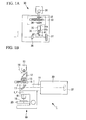
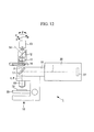
- the microscope 1 includes an illumination unit 30 for emitting incoherent light I, a detection optical system 10 for irradiating a specimen 19 with the incoherent light I coming from the illumination unit 30 and detecting fluorescence F emitted from the specimen 19, and a light-projecting section 11 optically connecting the illumination unit 30 and the detection optical system 10.
- the detection optical system 10 includes a stage 20 on which the specimen 19 is placed, an objective lens 18 disposed opposite the specimen 19 on the stage 20, a dichroic mirror (splitting section) 17 disposed on the optical axes of the illumination unit 30 and the objective lens 18, a barrier filter 16 for transmitting only light in a particular wavelength band, an imaging lens 15 for imaging the light passing through the barrier filter 16, an eyepiece 14 for the observer to observe the specimen 19, a prism 12 for reflecting part of the light imaged by the imaging lens 15 toward the eyepiece 14, and a CCD camera (photodetector) 13 for detecting the light passing through the prism 12.
- a CCD camera photodetector
- the objective lens 18 irradiates the specimen 19 on the stage 20 with the incoherent light I coming from the illumination unit 30 and collects the fluorescence F emitted from the specimen 19.
- the dichroic mirror 17 reflects the incoherent light I coming from the illumination unit 30 toward the objective lens 18 and transmits the fluorescence F coming from the specimen 19. With such properties, the dichroic mirror 17 splits off the fluorescence F emitted from the specimen 19 and collected by the objective lens 18 from the optical path of the incoherent light I.
- the barrier filter 16 blocks the incoherent light I coming from the illumination unit 30 and transmits only the fluorescence F coming from the specimen 19 and split off by the dichroic mirror 17.
- the CCD camera 13 is disposed at a position conjugate to the position of a DMD 37, described later, to detect the fluorescence F coming from the specimen 19 and split off by the dichroic mirror 17.
- the illumination unit 30 includes an incoherent light source 31 for emitting the incoherent light I, a shutter 32 disposed on the optical axis of the incoherent light source 31, an excitation filter 33 for transmitting only a component in a particular wavelength band, a light control mechanism 34 for adjusting the intensity of the incoherent light I passing through the excitation filter 33, an optical fiber (light-guiding member) 35 for guiding the incoherent light I adjusted by the light control mechanism 34, an irradiation optical system 36 for directing the incoherent light I guided by the optical fiber 35 toward the DMD 37 side, a DMD (microdevice array) 37 for selectively reflecting the incoherent light I directed by the irradiation optical system 36, and a projection lens 39 for projecting the incoherent light I selectively reflected by the DMD 37.
- an incoherent light source 31 for emitting the incoherent light I
- a shutter 32 disposed on the optical axis of the incoherent light source 31
- the shutter 32 has a drive mechanism for an opening/closing operation that closes the shutter 32 to block the incoherent light I emitted from the incoherent light source 31 and that opens the shutter 32 to allow the incoherent light I to pass therethrough.
- the excitation filter 33 transmits light having the wavelength necessary for excitation of a fluorescent substance in the specimen 19.
- the barrier filter 16 and the excitation filter 33 have a plurality of filters having different wavelength characteristics and a switching mechanism for switching among the plurality of filters, allowing the wavelength of the incoherent light I to be selected by switching among the filters.
- the optical fiber 35 such as a quartz fiber, has an entrance surface 35a on which the incoherent light I adjusted by the light control mechanism 34 is incident and an exit surface 35b to which the incident incoherent light I is guided by repeated total reflection.
- the irradiation optical system 36 includes a condensing lens 41 for collecting the incoherent light I guided by the optical fiber 35 and a mirror 42 disposed between the condensing lens 41 and the DMD 37 and reflecting the incoherent light I collected by the condensing lens 41 toward the DMD 37.
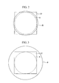
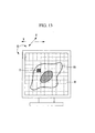
- the condensing lens 41 projects the exit surface 35b of the optical fiber 35 onto the DMD 37. As shown in Fig. 2 , additionally, the condensing lens 41 irradiates an irradiation region B larger than a microscope field A on the DMD 37 with the incoherent light I guided by the optical fiber 35.
- the DMD 37 has an array of movable micromirrors (microdevices) (not shown) for reflecting the incoherent light I directed by the irradiation optical system 36. With such a structure, the DMD 37 operates (turns on and off) the movable micromirrors to selectively reflect part or all of the incoherent light I directed by the irradiation optical system 36 toward the projection lens 39.
- the incoherent light I emitted from the incoherent light source 31 passes through the shutter 32 and the excitation filter 33, is adjusted by the light control mechanism 34, and is incident on the optical fiber 35.
- the incoherent light I incident on the optical fiber 35 is made uniform in the optical fiber 35 by repeated total reflection.
- the uniform incoherent light I is collected by the condensing lens 41 and is reflected by the mirror 42 toward the DMD 37.
- the incoherent light I reflected by the mirror 42 is imaged on the DMD 37.
- the incoherent light I imaged on the DMD 37 only the incoherent light I reflected by on-state movable micromirrors of the DMD 37 is reflected toward the projection lens 39.
- the incoherent light I projected by the projection lens 39 is reflected by the dichroic mirror 17 and is focused at a focal position on the specimen 19 by the objective lens 18.
- the fluorescent substance in the specimen 19 is excited to emit the fluorescence F.
- the emitted fluorescence F is collected by the objective lens 18, passes through the dichroic mirror 17, the barrier filter 16, the imaging lens 15, and the prism 12 in the above order, and is detected by the CCD camera 13, thus generating a fluorescence image.
- the movable micromirrors for reflecting the incoherent light I on the DMD 37 can be switched to vary the region irradiated with the incoherent light I on the specimen 19, thus obtaining an image of the specimen 19 in any region.
- the incoherent light I with which the specimen 19 is irradiated is made uniform by the optical fiber 35.
- the microscope 1 according to this embodiment can irradiate the specimen 19 with uniform incoherent light I without decreasing the amount of light, thus obtaining a fluorescence image without unevenness.
- the optical fiber 35 is a quartz fiber, the incoherent light I can be guided while being efficiently made uniform.
- a quartz fiber is suitable as the optical fiber 35 because it has high transmittance for visible light (400 to 600 nm).
- a diffuser an optical element such as a fiber rod, or Koehler (telecentric) illumination can be used; to maintain incoherence and efficiently make the incoherent light I uniform, as in this embodiment, an optical element such as a fiber rod is best suited.
- optical fiber 35 As the optical fiber 35, a large-diameter fiber matching the NA of the incoherent light source 31 is required.
- the incoherent light I can be efficiently made uniform.
- the specimen 19 can be irradiated with uniform incoherent light I while ensuring incoherence.
- Koehler illumination has problems such as unevenness because it has angular properties (light distribution properties).
- an area larger than the DMD 37 needs to be irradiated.
- critical illumination is advantageous in preserving incoherence. Accordingly, the irradiation optical system 36 is preferably a critical optical system rather than Koehler illumination.
- the irradiation optical system 36 may irradiate a region larger than the region where the movable micromirrors of the DMD 37 are arranged, with the incoherent light I guided by the optical fiber 35.
- NA of an optical fiber varies when the optical fiber is bent, which causes unevenness in the amount of light on the periphery of the irradiated region. Such unevenness in the amount of light is also caused by, for example, variations in NA due to the manufacturing process of the optical fiber.
- the overfill level may be set such that uneven illumination can be compensated for at the end surface of the optical fiber 35, and is preferably set such that, for example, a region about 1.2 times the area of the microscope field A is illuminated.
- the DMD 37 is preferably disposed such that the surface on which the movable micromirrors are arranged extends vertically, more preferably, such that the surface faces downward.
- the surface of the DMD 37 on which the movable micromirrors are arranged that is, the surface that selectively reflects or transmits the incoherent light I, can be made resistant to adhesion of foreign matter such as dust, thus preventing a degradation in the uniformity of the incoherent light I.
- a zoom mechanism 51 for changing the focal distance of the incoherent light I may be provided between the optical fiber 35 and the DMD 37.
- the focal distance of the incoherent light I can be changed to change the area of the region B irradiated with the incoherent light I on the specimen 19, thus obtaining an enlarged or reduced image of the specimen 19.
- the incoherent light I can be collected near the center of the DMD 37 to more intensely illuminate the center of the microscope field A, thus obtaining a brighter image.
- a shift mechanism 52 for shifting the incoherent light I in a direction perpendicular to the optical axis may be provided between the zoom mechanism 51 and the DMD 37.
- the incoherent light I can be shifted in a direction perpendicular to the optical axis to shift the irradiation region B collected by the zoom mechanism 51 to any region (for example, the peripheral region of the microscope field A). This allows any region to be intensely irradiated with the incoherent light I, thus obtaining a bright image in that region.
- the illumination unit 30 may be divided into a light source unit 45 including the incoherent light source 31, the shutter 32, the excitation filter 33, and the light control mechanism 34 and an optical unit 46 including the zoom mechanism 51, the shift mechanism 52, the irradiation optical system 36, the DMD 37, and the projection lens 39, and an optical fiber 53 optically connecting the light source unit 45 and the optical unit 46 may be provided.
- the incoherent light source 31 acting as a source of heat and vibration, can be separated from the detection optical system 10, thus improving the stability of illumination.
- the optical fiber 53 can be elongated to efficiently make the incoherent light I uniform, thus obtaining a fluorescence image without unevenness.
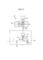
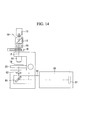
- a light source unit 60 that emits illumination light L having a wavelength band different from that of the incoherent light I may be provided, and a combining dichroic mirror (combining section) 65 may be provided between the projection lens 39 and the dichroic mirror 17.
- the light source unit 60 has the same configuration as the light source unit 45 described above except for the light source and includes an illumination light source 61 such as a mercury lamp, a shutter 62, an excitation filter 63, and a light control mechanism 64.
- an illumination light source 61 such as a mercury lamp
- a shutter 62 such as a shutter
- an excitation filter 63 such as a light control mechanism 64.
- the combining dichroic mirror 65 reflects the illumination light L coming from the light source unit 60 toward the dichroic mirror 17 and transmits the incoherent light I reflected by the DMD 37. With such properties, the combining dichroic mirror 65 combines the illumination light L coming from the illumination light source 61 and the incoherent light I coming from the incoherent light source 31.
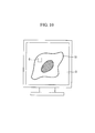
- the microscope 1 allows examination of the specimen 19 (examination region D) with the illumination light L having a wavelength band different from that of the incoherent light I while stimulating the specimen 19 by selectively irradiating a region C on the specimen 19 with the incoherent light I via the DMD 37.
- a second DMD (not shown) having an array of movable micromirrors for reflecting the illumination light L coming from the illumination light source 61 may be provided between the illumination light source 61 and the combining dichroic mirror 65.
- the incoherent light I coming from the incoherent light source 31 may be split into incoherent light I1 and incoherent light I2, and the specimen 19 may be irradiated with the light I1 and I2.
- the illumination unit 30 includes a dichroic mirror (splitting section) 71 disposed on the optical axis of the incoherent light source 31.
- the dichroic mirror 71 reflects a predetermined wavelength component (incoherent light I1) and transmits another wavelength component (incoherent light I2). With such properties, the dichroic mirror 71 splits the incoherent light I coming from the incoherent light source 31 into the incoherent light I1 and the incoherent light I2.
- a mirror 78 for deflecting the incoherent light I1, the shutter 32, the excitation filter 33, the light control mechanism 34, the optical fiber 35, the zoom mechanism 51, the shift mechanism 52, the irradiation optical system 36, the DMD 37, the projection lens 39, and a dichroic mirror (splitting section) 76, described later.
- a shutter 72 disposed on the optical axis of the incoherent light source 31, an excitation filter 73 for transmitting only a component in a particular wavelength band, a light control mechanism 74 for adjusting the intensity of the incoherent light I2 passing through the excitation filter 73, a projection lens 75 for projecting the incoherent light I2 adjusted by the light control mechanism 74, and the dichroic mirror 76.
- the projection lens 75 for example, a Koehler illumination optical system is used so that the entire field of view can be evenly illuminated.
- the dichroic mirror 76 reflects the incoherent light I1 reflected by the DMD 37 and transmits the incoherent light I2 passing through the dichroic mirror 71. With such properties, the dichroic mirror 76 combines the incoherent light I1 and the incoherent light I2.
- the dichroic mirror 71 reflects a component having a wavelength shorter than 450 nm and transmits a component having a wavelength of 450 nm or longer. This allows a wavelength around 405 nm to be selected as the central wavelength of the incoherent light I1 passing along the reflection optical path and a wavelength around 488 nm to be selected as the central wavelength of the incoherent light I2 passing along the transmission optical path. By doing so, GFP can be examined over the entire field of view with the incoherent light I2 while stimulating the specimen 19 with the incoherent light I1.
- the dichroic mirrors 71 and 76 have a plurality of filters having different wavelength characteristics and a switching mechanism for switching among the plurality of filters, allowing the wavelengths of the incoherent light I1 and I2 to be selected by switching among the filters.
- the microscope 1 according to this modification provides the same advantageous effects as the microscope 1 according to the fourth modification described above without using two light sources, that is, only using the incoherent light source 31. That is, as shown in Fig. 10 , the microscope 1 according to this modification allows examination of the specimen 19 (examination region D) with the incoherent light I2 having a wavelength band different from that of the incoherent light I1 while stimulating the specimen 19 by selectively irradiating the region C on the specimen 19 with the incoherent light I1 via the DMD 37.
- a second DMD (not shown) having an array of movable micromirrors for reflecting the incoherent light I2 may be provided between the light control mechanism 74 and the projection lens 75.
- a mechanism for adjusting the position of the CCD camera 13 in the X and Y directions (not shown) and a mechanism for adjusting the angle of rotation of the CCD camera 13 about the optical axis (not shown) may be provided on the mount of the CCD camera 13.
- the specimen 19 can be examined at any position by operating the position adjustment mechanism and can be examined at any angle by operating the angle-of-rotation adjustment mechanism.
- the position adjustment mechanism and the angle-of-rotation adjustment mechanism may instead be provided on the DMD 37 side.
- the illumination unit 30 for emitting the incoherent light I may be disposed opposite the objective lens 18 with the specimen 19 therebetween.
- reference numeral 81 denotes a mirror for reflecting the incoherent light I coming from the illumination unit 30 toward the specimen 19
- reference numeral 82 denotes a condenser lens for irradiating the specimen 19 with the incoherent light I reflected by the mirror 81.
- This structure eliminates the need for the splitting section, namely, the dichroic mirror 17 (see Fig. 1B ).
- the illumination unit 30 used in this modification may be any type of illumination unit 30 used in the embodiment and modifications described above.
- the DMD 37 has been described in the embodiments as selectively reflecting the incoherent light I, it may selectively transmit the incoherent light I.
- the light-guiding member has been described by taking an optical fiber, such as a quartz fiber, as an example, any member capable of guiding the incoherent light I by repeated total reflection, such as a light guide rod, can be used.
- the DMD 37 having a plurality of movable micromirrors has been described as an example of a microdevice array, it may instead be a liquid crystal array having a plurality of liquid crystal devices.
Claims (10)
- Mikroskop (1) aufweisend:eine inkohärente Lichtquelle (31), die dazu eingerichtet ist, inkohärentes Licht zu emittieren;ein Lichtführungselement (35), auf das das von der inkohärenten Lichtquelle (31) kommendes inkohärenten Licht einfällt und das dazu eingerichtet ist, das einfallende inkohärente Licht durch wiederholte Totalreflexion zu führen;eine Mikrovorrichtungsanordnung (37) mit einer Anordnung von Mikrovorrichtungen, von denen jede dazu eingerichtet ist, das durch das Lichtführungselement (35) geführte inkohärente Licht zu reflektieren oder zu transmittieren;ein optisches System zur Musterbeleuchtung, das dazu eingerichtet ist, eine Probe mit dem inkohärenten Licht, das von der Mikrovorrichtungsanordnung (37) reflektiert oder transmittiert wurde, zu bestrahlen;eine Objektivlinse (18), die dazu eingerichtet ist, das von der Probe kommende Licht zu sammeln;einen Fotodetektor (13), der an einer Position konjugiert zu der Position der Mikrovorrichtungsanordnung (37) angeordnet ist und der dazu eingerichtet ist, das von der Probe kommende und durch die Objektivlinse (18) gesammelte Licht zu erfassen;ein optisches System zur Bestrahlung (36), das dazu eingerichtet ist, die Mikrovorrichtungseinrichtung (37) mit dem durch das Lichtführungselement (35) geführte inkohärente Licht zu bestrahlen,dadurch gekennzeichnet, dassdas optische System zur Bestrahlung (36) dazu eingerichtet ist, eine Ausgangsfläche (35b) des Lichtführungselements (35) auf die Mikrovorrichtungsanordnung (37) zu projizieren, wobeidas Mikroskop (1) ferner einen Zoom-Mechanismus (51) aufweist, der zwischen dem Lichtführungselement (35) und der Mikrovorrichtungsanordnung (37) angeordnet ist, und der dazu eingerichtet ist, die Größe eines Bereichs, der mit dem inkohärenten Licht bestrahlt wurde, durch Ändern der Brennweite des inkohärenten Lichts auf der Mikrovorrichtungsanordnung (37) zu ändern.
- Mikroskop (1) nach Anspruch 1, bei dem das optische System zur Musterbeleuchtung die Objektivlinse (18) enthält, und
das Mikroskop (1) ferner einen Teilungsabschnitt (71) aufweist, der dazu eingerichtet ist, das von der Probe kommende und durch die Objektivlinse (18) gesammelte Licht von dem inkohärenten Licht abzuspalten und das Licht zu dem Fotodetektor (13) zu richten. - Mikroskop (1) nach Anspruch 1 oder 2, bei dem das optische System zur Musterbeleuchtung eine Kondensorlinse (41) enthält, die gegenüber der Objektivlinse (18) mit der Probe dazwischen angeordnet ist.
- Mikroskop (1) nach einem der Ansprüche 1 bis 3, bei dem das Lichtführungselement (35) eine Quarzfaser ist.
- Mikroskop (1) nach einem der Ansprüche 1 bis 4, bei dem das optische System zur Beleuchtung (36) dazu eingerichtet ist, einen Bereich, der größer als ein Bereich ist, in dem die Mikrovorrichtungen der Mikrovorrichtungsanordnung (37) angeordnet sind, mit dem durch das Lichtführungselement (35) geführte inkohärente Licht zu bestrahlen.
- Mikroskop (1) nach Anspruch 1, ferner aufweisend einen Verlagerungsmechanismus (52), der zwischen dem Zoom-Mechanismus (51) und der Mikrovorrichtungsanordnung (37) angeordnet ist, und der dazu eingerichtet ist, das inkohärente Licht in eine Richtung senkrecht zu einer optischen Achse von diesem zu verlagern.
- Mikroskop (1) nach einem der Ansprüche 1 bis 6, bei dem die inkohärente Lichtquelle (31) unabhängig bereitgestellt ist, und das Mikroskop (1) ferner eine optische Faser zwischen der inkohärenten Lichtquelle (31) und der Mikrovorrichtungsanordnung (37) aufweist.
- Mikroskop (1) nach einem der Ansprüche 1 bis 7, ferner aufweisend:eine Beleuchtungslichtquelle (61), die dazu eingerichtet ist, Beleuchtungslicht mit einem Wellenlängenband, das sich von dem des inkohärenten Lichts unterscheidet, zu emittieren; undeinen Kombinationsabschnitt (65), der zwischen der Mikrovorrichtungsanordnung (37) und der Objektivlinse (18) angeordnet ist, und der dazu eingerichtet ist, das von der Beleuchtungslichtquelle (61) kommende Beleuchtungslicht und das von der inkohärenten Lichtquelle (31) kommende inkohärente Licht zu kombinieren.
- Mikroskop (1) nach einem der Ansprüche 1 bis 8, bei dem die Mikrovorrichtungsanordnung (37) so angeordnet ist, dass eine Fläche, auf der die Mikrovorrichtungen angeordnet sind, seitwärts oder nach unten zeigt.
- Mikroskop (1) nach einem der Ansprüche 1 bis 9, ferner aufweisend eine Beleuchtungslichtquelle (61), die dazu eingerichtet ist, Beleuchtungslicht mit einem Wellenlängenband, das sich von dem des inkohärenten Lichts unterscheidet, zu emittieren,
wobei der Fotodetektor (13) dazu eingerichtet ist, Licht, das von der Probe emittiert wurde durch Bestrahlung mit dem von der Beleuchtungslichtquelle (61) kommenden Beleuchtungslicht, zu erfassen.
Applications Claiming Priority (1)
| Application Number | Priority Date | Filing Date | Title |
|---|---|---|---|
| JP2009245279 | 2009-10-26 |
Publications (3)
| Publication Number | Publication Date |
|---|---|
| EP2315065A2 EP2315065A2 (de) | 2011-04-27 |
| EP2315065A3 EP2315065A3 (de) | 2011-07-06 |
| EP2315065B1 true EP2315065B1 (de) | 2015-05-13 |
Family
ID=43500598
Family Applications (1)
| Application Number | Title | Priority Date | Filing Date |
|---|---|---|---|
| EP20100013563 Not-in-force EP2315065B1 (de) | 2009-10-26 | 2010-10-12 | Mikroskop |
Country Status (3)
| Country | Link |
|---|---|
| US (1) | US20110102888A1 (de) |
| EP (1) | EP2315065B1 (de) |
| JP (1) | JP5649911B2 (de) |
Families Citing this family (12)
| Publication number | Priority date | Publication date | Assignee | Title |
|---|---|---|---|---|
| US9743020B2 (en) | 2010-03-23 | 2017-08-22 | California Institute Of Technology | Super resolution optofluidic microscopes for 2D and 3D imaging |
| US9643184B2 (en) | 2010-10-26 | 2017-05-09 | California Institute Of Technology | e-Petri dishes, devices, and systems having a light detector for sampling a sequence of sub-pixel shifted projection images |
| US9569664B2 (en) * | 2010-10-26 | 2017-02-14 | California Institute Of Technology | Methods for rapid distinction between debris and growing cells |
| WO2012058233A2 (en) | 2010-10-26 | 2012-05-03 | California Institute Of Technology | Scanning projective lensless microscope system |
| CN103534627A (zh) | 2011-03-03 | 2014-01-22 | 加州理工学院 | 光导像素 |
| JP6042887B2 (ja) * | 2011-07-24 | 2016-12-14 | ジーイー・ヘルスケア・バイオサイエンス・コーポレイション | ポリクロイックミラーチェンジャー付き蛍光顕微鏡 |
| CA2871658C (en) * | 2012-04-23 | 2015-09-15 | Siemens Healthcare Diagnostics Inc. | Biological assay sample analyzer |
| JP2014092682A (ja) | 2012-11-02 | 2014-05-19 | Olympus Corp | 顕微鏡用照明装置及びそれを備えた顕微鏡 |
| DE102012111452B3 (de) * | 2012-11-27 | 2014-03-20 | Karlsruher Institut für Technologie | Optische Anordnung, ihre Verwendung und Verfahren zur Aufnahme eines Bildes |
| WO2014152845A1 (en) | 2013-03-20 | 2014-09-25 | Siemens Healthcare Diagnostics Inc. | Light and shutter for a sample analyzer |
| JP6430532B2 (ja) * | 2013-12-27 | 2018-11-28 | センソファー メディカル, エセ.エレ. | ステント状物体を光学的に検査・分析する装置および方法 |
| DE102017100262A1 (de) * | 2017-01-09 | 2018-07-12 | Carl Zeiss Microscopy Gmbh | Verfahren zur Erzeugung eines dreidimensionalen Modells einer Probe in einem digitalen Mikroskop und digitales Mikroskop |
Family Cites Families (23)
| Publication number | Priority date | Publication date | Assignee | Title |
|---|---|---|---|---|
| JPH0530823U (ja) * | 1991-10-03 | 1993-04-23 | オリンパス光学工業株式会社 | システム顕微鏡 |
| US6121984A (en) * | 1995-01-11 | 2000-09-19 | Texas Instruments Incorporated | DMD modulated continuous wave light source for imaging systems |
| DE19644662C2 (de) * | 1996-10-25 | 2000-04-13 | Leica Microsystems | Beleuchtungseinrichtung für ein Mikroskop |
| DE19835072A1 (de) * | 1998-08-04 | 2000-02-10 | Zeiss Carl Jena Gmbh | Anordnung zur Beleuchtung und/oder Detektion in einem Mikroskop |
| US7019376B2 (en) * | 2000-08-11 | 2006-03-28 | Reflectivity, Inc | Micromirror array device with a small pitch size |
| US6545758B1 (en) * | 2000-08-17 | 2003-04-08 | Perry Sandstrom | Microarray detector and synthesizer |
| JP3634343B2 (ja) | 2001-09-03 | 2005-03-30 | 株式会社林創研 | デジタル制御走査方法および装置 |
| US6885492B2 (en) * | 2001-11-08 | 2005-04-26 | Imaginative Optics, Inc. | Spatial light modulator apparatus |
| JP2003156698A (ja) * | 2001-11-22 | 2003-05-30 | Toshiba Corp | レーザ光源装置 |
| US7196843B2 (en) * | 2002-03-27 | 2007-03-27 | Olympus Optical Co., Ltd. | Confocal microscope apparatus |
| JP3731073B2 (ja) | 2002-09-17 | 2006-01-05 | 独立行政法人理化学研究所 | 顕微鏡装置 |
| DE102004015587A1 (de) * | 2003-04-04 | 2004-11-11 | Olympus Corporation | Fluoreszenzmikroskop mit totaler interner Reflexion |
| DE10317615B4 (de) * | 2003-04-11 | 2005-10-06 | Carl Zeiss Jena Gmbh | Fluoreszenzmikroskopanordnung |
| DE102004011770B4 (de) * | 2004-03-09 | 2005-12-15 | Leica Microsystems Heidelberg Gmbh | Mikroskop |
| DE102004034959A1 (de) * | 2004-07-16 | 2006-02-16 | Carl Zeiss Jena Gmbh | Lichtrastermikroskop mit punktförmiger Lichtquellenverteilung und Verwendung |
| JP2006154239A (ja) * | 2004-11-29 | 2006-06-15 | Olympus Corp | 顕微鏡 |
| EP1857851A4 (de) * | 2005-03-11 | 2008-07-16 | Sony Corp | Zoomobjektiv und abbildungsvorrichtung |
| JP3755888B2 (ja) * | 2005-06-14 | 2006-03-15 | 株式会社林創研 | バイオチップオンライン分析システム |
| JP2007121590A (ja) * | 2005-10-27 | 2007-05-17 | Yokogawa Electric Corp | 共焦点スキャナ |
| JP4869749B2 (ja) * | 2006-03-14 | 2012-02-08 | オリンパス株式会社 | 走査型顕微鏡 |
| JP2008203813A (ja) * | 2007-01-24 | 2008-09-04 | Olympus Corp | 走査型顕微鏡 |
| DE102007009551B3 (de) * | 2007-02-27 | 2008-08-21 | Ludwig-Maximilian-Universität | Vorrichtung für die konfokale Beleuchtung einer Probe |
| JP2009245279A (ja) | 2008-03-31 | 2009-10-22 | Nifty Corp | 広告配信方法及び広告配信プログラム |
-
2010
- 2010-10-12 EP EP20100013563 patent/EP2315065B1/de not_active Not-in-force
- 2010-10-19 US US12/907,196 patent/US20110102888A1/en not_active Abandoned
- 2010-10-25 JP JP2010238860A patent/JP5649911B2/ja not_active Expired - Fee Related
Also Published As
| Publication number | Publication date |
|---|---|
| US20110102888A1 (en) | 2011-05-05 |
| EP2315065A3 (de) | 2011-07-06 |
| JP5649911B2 (ja) | 2015-01-07 |
| EP2315065A2 (de) | 2011-04-27 |
| JP2011118371A (ja) | 2011-06-16 |
Similar Documents
| Publication | Publication Date | Title |
|---|---|---|
| EP2315065B1 (de) | Mikroskop | |
| JP5244605B2 (ja) | 顕微鏡 | |
| EP1857853B1 (de) | Beleuchtungsvorrichtung | |
| JP5621259B2 (ja) | 顕微鏡装置 | |
| JP4671463B2 (ja) | 照明光学系及び照明光学系を備えた顕微鏡 | |
| US7782529B2 (en) | Scanning microscope and method for examining a sample by using scanning microscopy | |
| US6823079B1 (en) | Device for examining samples | |
| JP2004086009A (ja) | 走査型レーザ顕微鏡システム | |
| JP2007506955A (ja) | エバネッセント波照明を備えた走査顕微鏡 | |
| US7170676B2 (en) | Illumination switching apparatus and method | |
| JP2011118264A (ja) | 顕微鏡装置 | |
| JP6805126B2 (ja) | 微小試料の光学的な検査および/または操作のための方法、顕微鏡、顕微鏡および/または方法の使用、照明装置 | |
| JP2006243723A (ja) | 対物レンズおよび顕微鏡 | |
| US8294984B2 (en) | Microscope | |
| JP5461527B2 (ja) | 試料をエバネッセント照明する装置および方法 | |
| JPWO2009142312A1 (ja) | 顕微鏡装置 | |
| JPWO2008087992A1 (ja) | 焦点検出装置、顕微鏡 | |
| JP5623654B2 (ja) | 共焦点レーザー走査顕微鏡 | |
| US20170153433A1 (en) | Confocal scanner, confocal microscope, and illumination method | |
| US9069167B2 (en) | Illumination apparatus for microscope and microscope using the same | |
| JP2005140956A (ja) | 焦点検出装置および蛍光顕微鏡 | |
| JP5583515B2 (ja) | レーザ顕微鏡用照明装置およびレーザ顕微鏡 | |
| JP2012141452A (ja) | 自動合焦機構および顕微鏡装置 | |
| JP2008175884A (ja) | レーザ顕微鏡 | |
| JP2004012702A (ja) | 蛍光観察用の落射照明装置およびそれを備えた蛍光顕微鏡 |
Legal Events
| Date | Code | Title | Description |
|---|---|---|---|
| PUAI | Public reference made under article 153(3) epc to a published international application that has entered the european phase |
Free format text: ORIGINAL CODE: 0009012 |
|
| 17P | Request for examination filed |
Effective date: 20101012 |
|
| AK | Designated contracting states |
Kind code of ref document: A2 Designated state(s): AL AT BE BG CH CY CZ DE DK EE ES FI FR GB GR HR HU IE IS IT LI LT LU LV MC MK MT NL NO PL PT RO RS SE SI SK SM TR |
|
| AX | Request for extension of the european patent |
Extension state: BA ME |
|
| PUAL | Search report despatched |
Free format text: ORIGINAL CODE: 0009013 |
|
| AK | Designated contracting states |
Kind code of ref document: A3 Designated state(s): AL AT BE BG CH CY CZ DE DK EE ES FI FR GB GR HR HU IE IS IT LI LT LU LV MC MK MT NL NO PL PT RO RS SE SI SK SM TR |
|
| AX | Request for extension of the european patent |
Extension state: BA ME |
|
| 17Q | First examination report despatched |
Effective date: 20131205 |
|
| GRAP | Despatch of communication of intention to grant a patent |
Free format text: ORIGINAL CODE: EPIDOSNIGR1 |
|
| INTG | Intention to grant announced |
Effective date: 20150105 |
|
| RIN1 | Information on inventor provided before grant (corrected) |
Inventor name: HONDA, SUSUMU Inventor name: NAKATA, TATSUO |
|
| GRAS | Grant fee paid |
Free format text: ORIGINAL CODE: EPIDOSNIGR3 |
|
| GRAA | (expected) grant |
Free format text: ORIGINAL CODE: 0009210 |
|
| AK | Designated contracting states |
Kind code of ref document: B1 Designated state(s): AL AT BE BG CH CY CZ DE DK EE ES FI FR GB GR HR HU IE IS IT LI LT LU LV MC MK MT NL NO PL PT RO RS SE SI SK SM TR |
|
| REG | Reference to a national code |
Ref country code: GB Ref legal event code: FG4D |
|
| REG | Reference to a national code |
Ref country code: CH Ref legal event code: EP |
|
| REG | Reference to a national code |
Ref country code: IE Ref legal event code: FG4D |
|
| REG | Reference to a national code |
Ref country code: AT Ref legal event code: REF Ref document number: 727045 Country of ref document: AT Kind code of ref document: T Effective date: 20150615 |
|
| REG | Reference to a national code |
Ref country code: DE Ref legal event code: R096 Ref document number: 602010024601 Country of ref document: DE Effective date: 20150625 |
|
| REG | Reference to a national code |
Ref country code: AT Ref legal event code: MK05 Ref document number: 727045 Country of ref document: AT Kind code of ref document: T Effective date: 20150513 |
|
| REG | Reference to a national code |
Ref country code: NL Ref legal event code: MP Effective date: 20150513 |
|
| REG | Reference to a national code |
Ref country code: LT Ref legal event code: MG4D |
|
| PG25 | Lapsed in a contracting state [announced via postgrant information from national office to epo] |
Ref country code: FI Free format text: LAPSE BECAUSE OF FAILURE TO SUBMIT A TRANSLATION OF THE DESCRIPTION OR TO PAY THE FEE WITHIN THE PRESCRIBED TIME-LIMIT Effective date: 20150513 Ref country code: ES Free format text: LAPSE BECAUSE OF FAILURE TO SUBMIT A TRANSLATION OF THE DESCRIPTION OR TO PAY THE FEE WITHIN THE PRESCRIBED TIME-LIMIT Effective date: 20150513 Ref country code: PT Free format text: LAPSE BECAUSE OF FAILURE TO SUBMIT A TRANSLATION OF THE DESCRIPTION OR TO PAY THE FEE WITHIN THE PRESCRIBED TIME-LIMIT Effective date: 20150914 Ref country code: HR Free format text: LAPSE BECAUSE OF FAILURE TO SUBMIT A TRANSLATION OF THE DESCRIPTION OR TO PAY THE FEE WITHIN THE PRESCRIBED TIME-LIMIT Effective date: 20150513 Ref country code: NO Free format text: LAPSE BECAUSE OF FAILURE TO SUBMIT A TRANSLATION OF THE DESCRIPTION OR TO PAY THE FEE WITHIN THE PRESCRIBED TIME-LIMIT Effective date: 20150813 Ref country code: LT Free format text: LAPSE BECAUSE OF FAILURE TO SUBMIT A TRANSLATION OF THE DESCRIPTION OR TO PAY THE FEE WITHIN THE PRESCRIBED TIME-LIMIT Effective date: 20150513 |
|
| PG25 | Lapsed in a contracting state [announced via postgrant information from national office to epo] |
Ref country code: RS Free format text: LAPSE BECAUSE OF FAILURE TO SUBMIT A TRANSLATION OF THE DESCRIPTION OR TO PAY THE FEE WITHIN THE PRESCRIBED TIME-LIMIT Effective date: 20150513 Ref country code: IS Free format text: LAPSE BECAUSE OF FAILURE TO SUBMIT A TRANSLATION OF THE DESCRIPTION OR TO PAY THE FEE WITHIN THE PRESCRIBED TIME-LIMIT Effective date: 20150913 Ref country code: GR Free format text: LAPSE BECAUSE OF FAILURE TO SUBMIT A TRANSLATION OF THE DESCRIPTION OR TO PAY THE FEE WITHIN THE PRESCRIBED TIME-LIMIT Effective date: 20150814 Ref country code: LV Free format text: LAPSE BECAUSE OF FAILURE TO SUBMIT A TRANSLATION OF THE DESCRIPTION OR TO PAY THE FEE WITHIN THE PRESCRIBED TIME-LIMIT Effective date: 20150513 Ref country code: BG Free format text: LAPSE BECAUSE OF FAILURE TO SUBMIT A TRANSLATION OF THE DESCRIPTION OR TO PAY THE FEE WITHIN THE PRESCRIBED TIME-LIMIT Effective date: 20150813 Ref country code: AT Free format text: LAPSE BECAUSE OF FAILURE TO SUBMIT A TRANSLATION OF THE DESCRIPTION OR TO PAY THE FEE WITHIN THE PRESCRIBED TIME-LIMIT Effective date: 20150513 |
|
| PG25 | Lapsed in a contracting state [announced via postgrant information from national office to epo] |
Ref country code: EE Free format text: LAPSE BECAUSE OF FAILURE TO SUBMIT A TRANSLATION OF THE DESCRIPTION OR TO PAY THE FEE WITHIN THE PRESCRIBED TIME-LIMIT Effective date: 20150513 Ref country code: DK Free format text: LAPSE BECAUSE OF FAILURE TO SUBMIT A TRANSLATION OF THE DESCRIPTION OR TO PAY THE FEE WITHIN THE PRESCRIBED TIME-LIMIT Effective date: 20150513 |
|
| REG | Reference to a national code |
Ref country code: DE Ref legal event code: R097 Ref document number: 602010024601 Country of ref document: DE |
|
| PG25 | Lapsed in a contracting state [announced via postgrant information from national office to epo] |
Ref country code: SK Free format text: LAPSE BECAUSE OF FAILURE TO SUBMIT A TRANSLATION OF THE DESCRIPTION OR TO PAY THE FEE WITHIN THE PRESCRIBED TIME-LIMIT Effective date: 20150513 Ref country code: RO Free format text: LAPSE BECAUSE OF NON-PAYMENT OF DUE FEES Effective date: 20150513 Ref country code: PL Free format text: LAPSE BECAUSE OF FAILURE TO SUBMIT A TRANSLATION OF THE DESCRIPTION OR TO PAY THE FEE WITHIN THE PRESCRIBED TIME-LIMIT Effective date: 20150513 Ref country code: CZ Free format text: LAPSE BECAUSE OF FAILURE TO SUBMIT A TRANSLATION OF THE DESCRIPTION OR TO PAY THE FEE WITHIN THE PRESCRIBED TIME-LIMIT Effective date: 20150513 |
|
| PLBE | No opposition filed within time limit |
Free format text: ORIGINAL CODE: 0009261 |
|
| STAA | Information on the status of an ep patent application or granted ep patent |
Free format text: STATUS: NO OPPOSITION FILED WITHIN TIME LIMIT |
|
| 26N | No opposition filed |
Effective date: 20160216 |
|
| PG25 | Lapsed in a contracting state [announced via postgrant information from national office to epo] |
Ref country code: IT Free format text: LAPSE BECAUSE OF FAILURE TO SUBMIT A TRANSLATION OF THE DESCRIPTION OR TO PAY THE FEE WITHIN THE PRESCRIBED TIME-LIMIT Effective date: 20150513 |
|
| PG25 | Lapsed in a contracting state [announced via postgrant information from national office to epo] |
Ref country code: LU Free format text: LAPSE BECAUSE OF FAILURE TO SUBMIT A TRANSLATION OF THE DESCRIPTION OR TO PAY THE FEE WITHIN THE PRESCRIBED TIME-LIMIT Effective date: 20151012 Ref country code: SI Free format text: LAPSE BECAUSE OF FAILURE TO SUBMIT A TRANSLATION OF THE DESCRIPTION OR TO PAY THE FEE WITHIN THE PRESCRIBED TIME-LIMIT Effective date: 20150513 |
|
| REG | Reference to a national code |
Ref country code: CH Ref legal event code: PL |
|
| GBPC | Gb: european patent ceased through non-payment of renewal fee |
Effective date: 20151012 |
|
| PG25 | Lapsed in a contracting state [announced via postgrant information from national office to epo] |
Ref country code: MC Free format text: LAPSE BECAUSE OF FAILURE TO SUBMIT A TRANSLATION OF THE DESCRIPTION OR TO PAY THE FEE WITHIN THE PRESCRIBED TIME-LIMIT Effective date: 20150513 |
|
| REG | Reference to a national code |
Ref country code: IE Ref legal event code: MM4A |
|
| PG25 | Lapsed in a contracting state [announced via postgrant information from national office to epo] |
Ref country code: CH Free format text: LAPSE BECAUSE OF NON-PAYMENT OF DUE FEES Effective date: 20151031 Ref country code: LI Free format text: LAPSE BECAUSE OF NON-PAYMENT OF DUE FEES Effective date: 20151031 Ref country code: GB Free format text: LAPSE BECAUSE OF NON-PAYMENT OF DUE FEES Effective date: 20151012 |
|
| REG | Reference to a national code |
Ref country code: FR Ref legal event code: ST Effective date: 20160630 |
|
| PG25 | Lapsed in a contracting state [announced via postgrant information from national office to epo] |
Ref country code: FR Free format text: LAPSE BECAUSE OF NON-PAYMENT OF DUE FEES Effective date: 20151102 Ref country code: BE Free format text: LAPSE BECAUSE OF FAILURE TO SUBMIT A TRANSLATION OF THE DESCRIPTION OR TO PAY THE FEE WITHIN THE PRESCRIBED TIME-LIMIT Effective date: 20150513 |
|
| PG25 | Lapsed in a contracting state [announced via postgrant information from national office to epo] |
Ref country code: IE Free format text: LAPSE BECAUSE OF NON-PAYMENT OF DUE FEES Effective date: 20151012 |
|
| PG25 | Lapsed in a contracting state [announced via postgrant information from national office to epo] |
Ref country code: HU Free format text: LAPSE BECAUSE OF FAILURE TO SUBMIT A TRANSLATION OF THE DESCRIPTION OR TO PAY THE FEE WITHIN THE PRESCRIBED TIME-LIMIT; INVALID AB INITIO Effective date: 20101012 Ref country code: SM Free format text: LAPSE BECAUSE OF FAILURE TO SUBMIT A TRANSLATION OF THE DESCRIPTION OR TO PAY THE FEE WITHIN THE PRESCRIBED TIME-LIMIT Effective date: 20150513 |
|
| PG25 | Lapsed in a contracting state [announced via postgrant information from national office to epo] |
Ref country code: CY Free format text: LAPSE BECAUSE OF FAILURE TO SUBMIT A TRANSLATION OF THE DESCRIPTION OR TO PAY THE FEE WITHIN THE PRESCRIBED TIME-LIMIT Effective date: 20150513 Ref country code: SE Free format text: LAPSE BECAUSE OF FAILURE TO SUBMIT A TRANSLATION OF THE DESCRIPTION OR TO PAY THE FEE WITHIN THE PRESCRIBED TIME-LIMIT Effective date: 20150513 Ref country code: NL Free format text: LAPSE BECAUSE OF FAILURE TO SUBMIT A TRANSLATION OF THE DESCRIPTION OR TO PAY THE FEE WITHIN THE PRESCRIBED TIME-LIMIT Effective date: 20150513 |
|
| PG25 | Lapsed in a contracting state [announced via postgrant information from national office to epo] |
Ref country code: MT Free format text: LAPSE BECAUSE OF FAILURE TO SUBMIT A TRANSLATION OF THE DESCRIPTION OR TO PAY THE FEE WITHIN THE PRESCRIBED TIME-LIMIT Effective date: 20150513 Ref country code: TR Free format text: LAPSE BECAUSE OF FAILURE TO SUBMIT A TRANSLATION OF THE DESCRIPTION OR TO PAY THE FEE WITHIN THE PRESCRIBED TIME-LIMIT Effective date: 20150513 |
|
| PG25 | Lapsed in a contracting state [announced via postgrant information from national office to epo] |
Ref country code: MK Free format text: LAPSE BECAUSE OF FAILURE TO SUBMIT A TRANSLATION OF THE DESCRIPTION OR TO PAY THE FEE WITHIN THE PRESCRIBED TIME-LIMIT Effective date: 20150513 |
|
| PG25 | Lapsed in a contracting state [announced via postgrant information from national office to epo] |
Ref country code: AL Free format text: LAPSE BECAUSE OF FAILURE TO SUBMIT A TRANSLATION OF THE DESCRIPTION OR TO PAY THE FEE WITHIN THE PRESCRIBED TIME-LIMIT Effective date: 20150513 |
|
| PGFP | Annual fee paid to national office [announced via postgrant information from national office to epo] |
Ref country code: DE Payment date: 20191021 Year of fee payment: 10 |
|
| REG | Reference to a national code |
Ref country code: DE Ref legal event code: R119 Ref document number: 602010024601 Country of ref document: DE |
|
| PG25 | Lapsed in a contracting state [announced via postgrant information from national office to epo] |
Ref country code: DE Free format text: LAPSE BECAUSE OF NON-PAYMENT OF DUE FEES Effective date: 20210501 |