EP2311552B1 - Flüssigkeitsmischer und verwendung des flüssigkeitsmischers - Google Patents
Flüssigkeitsmischer und verwendung des flüssigkeitsmischers Download PDFInfo
- Publication number
- EP2311552B1 EP2311552B1 EP09804931.5A EP09804931A EP2311552B1 EP 2311552 B1 EP2311552 B1 EP 2311552B1 EP 09804931 A EP09804931 A EP 09804931A EP 2311552 B1 EP2311552 B1 EP 2311552B1
- Authority
- EP
- European Patent Office
- Prior art keywords
- flow path
- fluid
- fluid mixer
- set forth
- substance
- Prior art date
- Legal status (The legal status is an assumption and is not a legal conclusion. Google has not performed a legal analysis and makes no representation as to the accuracy of the status listed.)
- Not-in-force
Links
Images


Classifications
-
- B—PERFORMING OPERATIONS; TRANSPORTING
- B01—PHYSICAL OR CHEMICAL PROCESSES OR APPARATUS IN GENERAL
- B01F—MIXING, e.g. DISSOLVING, EMULSIFYING OR DISPERSING
- B01F25/00—Flow mixers; Mixers for falling materials, e.g. solid particles
-
- C—CHEMISTRY; METALLURGY
- C10—PETROLEUM, GAS OR COKE INDUSTRIES; TECHNICAL GASES CONTAINING CARBON MONOXIDE; FUELS; LUBRICANTS; PEAT
- C10L—FUELS NOT OTHERWISE PROVIDED FOR; NATURAL GAS; SYNTHETIC NATURAL GAS OBTAINED BY PROCESSES NOT COVERED BY SUBCLASSES C10G OR C10K; LIQUIFIED PETROLEUM GAS; USE OF ADDITIVES TO FUELS OR FIRES; FIRE-LIGHTERS
- C10L3/00—Gaseous fuels; Natural gas; Synthetic natural gas obtained by processes not covered by subclass C10G, C10K; Liquefied petroleum gas
-
- B—PERFORMING OPERATIONS; TRANSPORTING
- B01—PHYSICAL OR CHEMICAL PROCESSES OR APPARATUS IN GENERAL
- B01F—MIXING, e.g. DISSOLVING, EMULSIFYING OR DISPERSING
- B01F23/00—Mixing according to the phases to be mixed, e.g. dispersing or emulsifying
-
- B—PERFORMING OPERATIONS; TRANSPORTING
- B01—PHYSICAL OR CHEMICAL PROCESSES OR APPARATUS IN GENERAL
- B01F—MIXING, e.g. DISSOLVING, EMULSIFYING OR DISPERSING
- B01F25/00—Flow mixers; Mixers for falling materials, e.g. solid particles
- B01F25/40—Static mixers
- B01F25/42—Static mixers in which the mixing is affected by moving the components jointly in changing directions, e.g. in tubes provided with baffles or obstructions
- B01F25/43—Mixing tubes, e.g. wherein the material is moved in a radial or partly reversed direction
- B01F25/431—Straight mixing tubes with baffles or obstructions that do not cause substantial pressure drop; Baffles therefor
- B01F25/4314—Straight mixing tubes with baffles or obstructions that do not cause substantial pressure drop; Baffles therefor with helical baffles
-
- B—PERFORMING OPERATIONS; TRANSPORTING
- B01—PHYSICAL OR CHEMICAL PROCESSES OR APPARATUS IN GENERAL
- B01F—MIXING, e.g. DISSOLVING, EMULSIFYING OR DISPERSING
- B01F25/00—Flow mixers; Mixers for falling materials, e.g. solid particles
- B01F25/40—Static mixers
- B01F25/42—Static mixers in which the mixing is affected by moving the components jointly in changing directions, e.g. in tubes provided with baffles or obstructions
- B01F25/43—Mixing tubes, e.g. wherein the material is moved in a radial or partly reversed direction
- B01F25/432—Mixing tubes, e.g. wherein the material is moved in a radial or partly reversed direction with means for dividing the material flow into separate sub-flows and for repositioning and recombining these sub-flows; Cross-mixing, e.g. conducting the outer layer of the material nearer to the axis of the tube or vice-versa
- B01F25/4323—Mixing tubes, e.g. wherein the material is moved in a radial or partly reversed direction with means for dividing the material flow into separate sub-flows and for repositioning and recombining these sub-flows; Cross-mixing, e.g. conducting the outer layer of the material nearer to the axis of the tube or vice-versa using elements provided with a plurality of channels or using a plurality of tubes which can either be placed between common spaces or collectors
-
- B—PERFORMING OPERATIONS; TRANSPORTING
- B01—PHYSICAL OR CHEMICAL PROCESSES OR APPARATUS IN GENERAL
- B01F—MIXING, e.g. DISSOLVING, EMULSIFYING OR DISPERSING
- B01F25/00—Flow mixers; Mixers for falling materials, e.g. solid particles
- B01F25/40—Static mixers
- B01F25/42—Static mixers in which the mixing is affected by moving the components jointly in changing directions, e.g. in tubes provided with baffles or obstructions
- B01F25/43—Mixing tubes, e.g. wherein the material is moved in a radial or partly reversed direction
- B01F25/433—Mixing tubes wherein the shape of the tube influences the mixing, e.g. mixing tubes with varying cross-section or provided with inwardly extending profiles
- B01F25/4331—Mixers with bended, curved, coiled, wounded mixing tubes or comprising elements for bending the flow
-
- C—CHEMISTRY; METALLURGY
- C10—PETROLEUM, GAS OR COKE INDUSTRIES; TECHNICAL GASES CONTAINING CARBON MONOXIDE; FUELS; LUBRICANTS; PEAT
- C10L—FUELS NOT OTHERWISE PROVIDED FOR; NATURAL GAS; SYNTHETIC NATURAL GAS OBTAINED BY PROCESSES NOT COVERED BY SUBCLASSES C10G OR C10K; LIQUIFIED PETROLEUM GAS; USE OF ADDITIVES TO FUELS OR FIRES; FIRE-LIGHTERS
- C10L1/00—Liquid carbonaceous fuels
- C10L1/32—Liquid carbonaceous fuels consisting of coal-oil suspensions or aqueous emulsions or oil emulsions
Definitions
- the present invention was made in consideration of the above problem in the prior art and has as its object the provision of a fluid mixer and a use of a fluid mixer which can mix fluid while making a distribution of concentration or distribution of temperature of the fluid in the direction of flow uniform without any unevenness and which are both compact and facilitate piping work.
- the fluid mixer is provided with a main body part formed so that the fluid inlet is arranged at one end face, the fluid outlet is arranged at the other end face, a spiral groove is formed at an outer circumference, the second flow path is arranged coaxially with a center axis of a spiral of the spiral groove, and a plurality of communicating holes communicate the second flow path and the spiral groove and is provided with a housing fitting with an outer circumferential surface of the main body part, the spiral groove and the inner circumferential surface of the housing forming the spiral flow path and the communicating holes becoming the branch flow paths, as a second characterizing feature.
- the spiral flow path is formed so that a flow section area becomes gradually smaller from one end connected with the first flow path to the other end part, as a fourth characterizing feature.
- the substance is a gas or liquid, as a 12th characterizing feature.
- the fluid mixer is used to make a mixing ratio of at least two substances uniform in a line in which a mixing ratio of the substances changes over time, as a 13th characterizing feature.
- the substance is at least a first liquid chemical and a second liquid chemical or a metal, as a 17th characterizing feature.
- the substance is an at least first nonflammable gas and a second nonflammable gas or steam, as a 24th characterizing feature.
- the substance is any one of a first synthesis intermediate, second synthesis intermediate, additive, liquid chemical, or metal, as a 26th characterizing feature.
- the water and chemical are mixed and temporarily become weaker in chemical concentration.
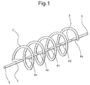
- the partially denser concentration chemical flowing through the flow path flows in from the fluid inlet 5 to the first flow path 1 and flows to the spiral flow path 2.
- part of that flows through the branch flow path 4a passes through the second flow path 3, and flows to the fluid outlet 6.
- the remaining chemical flows to the downstream side of the spiral flow path 2.
- part of the denser concentration remaining chemical flows through the location where the branch flow path 4b is connected, part of that flows through the branch flow path 4b, passes through the second flow path 3, and flows to the fluid outlet 6.
- the remaining chemical flows to the downstream side of the spiral flow path 2. Further, when the part of the denser concentration remaining chemical flows through the location where the branch flow path 4c is connected in the same way as the chemical flowing through the branch flow path 4b, part of that flows through the branch flow path 4c, passes through the second flow path 3, and flows to the fluid outlet 6. Below, in the same way as in 4a, 4b, and 4c, the part of the denser concentration remaining chemical flows through the 4d and 4e, passes through the second flow path 3, and flows to the fluid outlet 6.
- the branch flow paths 4a to 4e are provided so as to be at positions at equal intervals along the axis of the second flow path 3, but to adjust the time difference of the fluid flowing through the branch flow paths 4a to 4e, it is possible to freely set the positions of connection or to form the spiral flow path 2 to become gradually smaller in flow section area from the one end part connected to the first flow path 1 toward the other end part.
- the number of the branch flow paths 4a to 4e is not particularly limited. Provision of a large number of branch flow paths 4a to 4e enables the distribution of concentration of the fluid in the direction of flow to be made finely uniform without any unevenness.
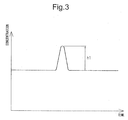
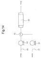
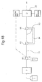
- concentration meters 100 and 101 are set at the upstream side and downstream side of the fluid mixer of FIG. 1 to create an apparatus for mixing and passing on pure water and a chemical from the upstream side.
- FIG. 3 is a graph of the upstream side of the concentration meter 100 set at the fluid mixer, but here the abscissa shows the elapsed time, while the ordinate shows the concentration.
- a peak (h1) such as in the figure appears.
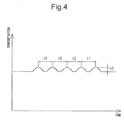
- FIG. 4 is a graph of a concentration member 101 set at the downstream side of the fluid mixer, but the peak of concentration is dispersed into five. The heights of the peaks (h2) become about one-fifth the previous case.
- the interval t1 between the peaks of the concentration corresponds to the time from when the fluid passes the position of the branch flow path 4a inside the spiral flow path 2 to when it reaches the branch flow path 4b.
- t2 corresponds to the time from the branch flow path 4b to the branch flow path 4c
- t3 to the time from the branch flow path 4c to the branch flow path 4d
- t4 to the time from the branch flow path 4d to the branch flow path 4e.
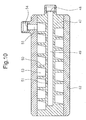
- Reference numeral 7 is a PTFE main body part.
- the main body part 7 is formed into a columnar shape.
- a fluid inlet 8 and a first flow path 9 connected to the fluid inlet 8 are connected.
- a fluid outlet 10 and a second flow path 11 connected to the fluid outlet 10 is provided.
- the first and second flow paths 9 and 11 are arranged at positions on the center axis of the main body part 7.
- a spiral groove 12 is provided at the outer circumferential surface of the main body part 7.
- One end part of the spiral groove 12 is connected to the first flow path 9.
- Communicating holes 13 forming a plurality of branch flow paths are provided communicating the inner circumferential surface of the second flow path 11 and the bottom surface of the spiral groove 12. Further, the communicating hole 13 positioned at the location nearest the fluid outlet 10 side is communicated with the other end part of the spiral groove 12.
- Reference numeral 14 is a cylindrical member forming a PFA tube housing.
- the cylindrical member 14 is formed into a substantially cylindrical shape.
- the inside diameter of the cylindrical member 14 is formed to approximately the same diameter as the outside diameter of the main body part 7.
- the member is fit over the outer circumferential surface of the main body part 7 in a sealed state.
- a spiral flow path 15 is formed between the spiral groove 12 of the main body part 7 and the inner circumferential surface of the cylindrical member 14.
- the communicating holes 13 which communicate the inner circumferential surface of the second flow path 11 and the bottom surface of the spiral groove 12 can be easily formed, so it is possible to freely determine the positions of provision and number of provision of the communicating holes 13, possible to finely and evenly adjust the offset times of flow, and possible to more finely make the distribution of concentration of the fluid in the direction of flow uniform without any unevenness.
- the flow path is complicated, the work involved is relatively easy and the number of parts is also small, so production is easy.
- the structure of the flow path is kept small, so the fluid mixer can be made small in size and can be installed without taking up piping space. Further, even when connecting the fluid mixer to a pipeline, installation is completed by just connecting couplings to the fluid inlet 8 and the fluid outlet 10, so the piping work is easy and can be performed in a short time.
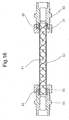
- the spiral flow path 23 is preferably formed so as to become gradually smaller in flow section area from the one end part connected with the first flow path 24 toward the other end part. This is preferable since the fluid flowing through the spiral flow path 23 experiences a pressure loss due to fluid being divided off and flowing from the communicating holes 25 and the flow rate at the downstream side of the spiral flow path 23 falls, so by making the spiral flow path 23 gradually smaller in flow section area, it is possible to make the fluid flow by a constant rate even if pressure loss occurs and to stabilize the time difference of the flow of the fluid divided off. Note that, as the method of reducing the flow section area of the spiral flow path 23, as shown in FIG.
- the main body part 19 it is possible to provide the main body part 19 to gradually be reduced in diameter of its outer circumferential surface from the fluid inlet 26 toward the fluid outlet 27 and fit a cylindrical member 20 matched with the outer circumferential surface shape so as to form a spiral flow path 23 or, in addition, form the spiral groove to become gradually shallower in depth (not shown), form the spiral groove to become gradually narrower in width (not shown), or to form it by a combination of these.
- the inner circumferential surface of the second flow path 28 is formed to gradually expand in diameter from the upstream part (fluid inlet 29 side) to the fluid outlet 30. This is preferable so as to make the fluid flowing through the spiral flow path 31 first divided off and flowing from the communicating hole 32a to the second flow path 28 flow through the second flow path 28 and flow out from the fluid outlet 30 the fastest, then gradually slow the flow rates of fluid successively divided off and flowing from the communicating holes 32 through the second flow path 28 so as to better clarify the time differences of the flowing fluid.
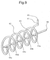
- the fluid mixer is provided with a fluid outlet 46 from which the fluid flows out, a second flow path 43 connected to the fluid outlet 46, and a spiral flow path 42 having the second flow path 43 as the center axis of the spiral.
- a fluid inlet 45 into which the fluid flows and a first flow path 41 connected to the fluid inlet 45 are provided connected with one end part of the spiral flow path 42 at the fluid outlet side.
- five branch flow paths 44a to 44e are provided connected with the second flow path 43.
- the branch flow path 443 positioned at the location furthest from the fluid outlet 46 side is provided connected to the other end part of the spiral flow path 42.
- tubes etc. may be used for pipe connections.
- the remaining chemical flows to the downstream side of the spiral flow path 42. Further, when the part of the denser concentration remaining chemical, in the same way as the chemical flowing through the branch flow path 44b, flows through the location connected to the branch flow path 44c, part of that flows through the branch flow path 44c, passes through the second flow path 43, and flows to the fluid outlet 46. Below, in the same way as 44a, 44b, and 44c, the part of the denser concentration remaining chemical flows through 44d and 44e, passes through the second flow path 43, and flows out to the fluid outlet 46.
- part of the denser concentration chemical flowing through the branch flow path 44a passes through the second flow path 49 by the shortest route and flows out from the fluid outlet 48 faster than the other denser concentration chemical.
- parts of denser concentration chemical running over routes gradually becoming longer flow out in the order of the branch flow path 44b, branch flow path 44c, branch flow path 44d, and branch flow path 44e. That is, the partially denser concentration chemical flowing through the flow path fluid is divided into five parts by the mixer.
- the non-denser concentration chemical being mixed with them, the fluid can be mixed uniformly in the flow direction.
- the distance from the branch flow paths 44a to 44e to the fluid outlet 46 becomes longer by each constant distance in the order of division, it is possible to make the time difference clearer.
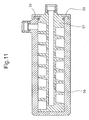
- Reference numeral 52 is a cylindrical member forming a polypropylene housing.
- the cylindrical member 52 is formed into a substantial cylindrical shape.
- the inside diameter of the cylindrical member 52 is formed to about the same diameter as the outside diameter of the main body part 47. By being shrink fit by the main body part 7, this is fit in a state sealed with the outer circumferential surface of the main body part 47.
- the spiral groove 50 of the main body part 47 and the inner circumferential surface of the cylindrical member 52 form the spiral flow path 53.
- a fluid inlet 54 is provided at the side surface of the cylindrical member 52 at the fluid outlet 48 side.
- a first flow path 55 is provided connecting the fluid inlet 54 and one end of the spiral groove 50 of the main body part 47 at the fluid outlet 48 side.
- the fourth embodiment is similar to the second embodiment in its action of making the distribution of concentration of the fluid in the flow direction uniform without any unevenness, so the explanation will be omitted.
- the communicating holes 51 are preferably formed so that the flow section areas become substantially identical.
- the spiral flow path 53 is preferably formed the flow section area gradually becomes smaller from one end connected with the first flow path 55 toward the other end side.
- the inner circumferential surface of the second flow path 49 is formed to gradually expand in diameter from the upstream part toward the fluid outlet 48.
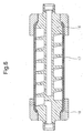
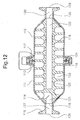
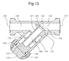
- Communicating holes 125 forming a plurality of branch flow paths communicating the inner circumferential surface of the second flow path 122 and the bottom surface of the spiral groove 123 are provided. Further, the communicating hole 125 positioned at the location nearest to the fluid outlet 120 side is communicated with the other end part of the spiral groove 123.
- the two end parts of the main body part 116 are reduced in diameters to shapes matching the inner circumferential surfaces of the first and second cylindrical parts 111 and 112.
- the outer circumferences are formed to approximately the same diameters as the first and second cylindrical parts 111 and 112.
- the main body part 116 is inserted into the opening parts of the flange parts 113 and 117 of the sides of the first and second cylindrical parts 111 and 112 not reduced in diameter.
- a gasket 124 is provided between the end faces of the flange parts 113 and 117.
- the flange parts 113 and 117 are fastened by a clamp 118.
- the inlet flow path 127 of the first cylindrical part 111 is communicated with the first flow path 121 of the main body part 116, while the outlet flow path 129 of the second cylindrical part 112 is communicated with the second flow path 122 of the main body part 116.
- the first and second cylindrical parts 111 and 112 form a housing.
- the flange parts 113 and 117 of the present embodiment are connected in the same way as the method of connection of a ferrule coupling.
- a ferrule coupling may also be used.
- a ferrule coupling can be used for facilitating assembly for forming a fluid mixer.
- the flow path of the main body part may be made the same shape as the fourth embodiment.
- the closed-bottom cylindrical shape first cylindrical part and the second cylindrical part provided with the fluid inlet and fluid outlet are connected by a ferrule coupling part (not shown).
- the cap nut 142 it is also possible to not use the cap nut 142, but to form a female thread on the lid member 140 and screw it to the body 131. It is also possible to provide the opening part 135 of the body 131 with a female thread and screw a lid member 140 having a male thread over it. Further, the method of fastening is not particularly limited so long as being able to fasten the body 131 and the lid member 140 and may be a bayonet, ferrule, screw, or other type in addition to screwing.
- a fluid mixer is installed in a line in which the temperature or concentration of the flowing substance changes along with time.
- the substance which flows as a fluid is not limited so long as being a gas or liquid.
- the substance run as a fluid at this time may be any of a gas, liquid, solid, or powder.
- the solid or powder has to be able to be run through a line. It may be mixed with a gas or liquid in advance. Note that, it is also possible to make the apparatus one in which lines through which three or more substances flow are merged and in which three or more substances are thereby mixed by the fluid mixer.
- the liquid fertilizer may be any liquid fertilizer for agricultural use. Manure or a chemical fertilizer etc. may be mentioned.
- liquid chemicals which does not fall under the above categories may also be used.
- Hydrochloric acid, sulfuric acid, acetic acid, nitric acid, formic acid, fluoric acid, sodium hydroxide, potassium hydroxide, calcium hydroxide, barium hydroxide, ammonium hydroxide, sodium silicate, oil, etc. may be mentioned.
- the liquid chemicals mentioned here are also used chemicals corresponding to the above categories.
- the pH adjuster used may be the above pH adjuster.
- the flocculant is not particularly limited so long as causing flocculation of the waste liquor. Ammonium sulfate, polyferrous sulfate, polyaluminum chloride, polysilica iron, calcium sulfate, ferrous chloride, slaked lime, etc. may be mentioned.
- the microorganism need only be one which promotes fermentation or breakdown of waste liquor. A mold, yeast, or other fungi, bacteria or other microorganisms etc. may be mentioned.
- a detergent dispersant As a lubrication oil additive, a detergent dispersant, antioxidant, viscosity index improver/pour point depressant, oiliness agent/extreme pressure additive, antiwear agent, antirust/anticorrosive agent, etc. may be mentioned, while as a grease additive, a structural stabilizer, filler, or other fuel oil additive etc. may be mentioned.
- the water referred to here may be pure water, distilled water, tap water, industrial water, etc. It is not particularly limited so long as water meeting the conditions of the substances to be mixed. Further, the temperature of the water is not particularly limited. Hot water or cold water may be used.
- the "resin” referred to here is a molten resin, liquid resin, or other main ingredient of an adhesive or coat forming ingredient of a coating.
- the molten resin is not particularly limited so long as a resin which can be injection molded or extruded.
- Polyethylene polypropylene, polyvinyl chloride, polystyrene, tetrafluoroethylene-perfluoroalkyl vinyl ether copolymer, ABS resin, acryl resin, polyamide, nylon, polyacetal, polycarbonate, modified polyphenylene ether, polybutylene terephthalate, polyethylene terephthalate, polyphenylene sulfide, polyether ether ketone, etc. may be mentioned.
- coloring agents zinc white, lead white, lithopone, titanium dioxide, precipitated barium sulfate, barite powder, red lead, iron oxide red, yellow lead, zinc yellow, ultramarine blue, potassium ferrocyanide, carbon black, and other pigments may be mentioned.
- the above resin is a molten resin
- the fluid mixer 65 between the nozzle of the molding machine and mold for injection molding or, in the case of an extruder, arrange the fluid mixer 65 between the extruder and die for extrusion.
- the first and second food materials need only be beverages or foods which can flow through pipelines.
- Flour potato starch, strong wheat flour, weak wheat flour, buckwheat flour, powdered milk, coffee, cocoa, and other powder materials or meat, wakame seaweed, sesame seeds, green laver, kezuribushi dried fish shavings, bread crumbs, minced or grated food or other small solid foods etc. may be mentioned.
- the measuring device may be any which can measure a parameter of the fluid required such as a flowmeter, current meter, densitometer, or pH meter.
- a static mixer in the flow path at the downstream side of the merging part of the lines. The fluid mixer may be used to make flow uniform in the axial direction of the flow path, while the static mixer may be used to make the flow uniform in the diametrical direction of the flow path, so the fluid can be mixed more uniformly.
Landscapes
- Chemical & Material Sciences (AREA)
- Chemical Kinetics & Catalysis (AREA)
- Dispersion Chemistry (AREA)
- Oil, Petroleum & Natural Gas (AREA)
- Engineering & Computer Science (AREA)
- General Chemical & Material Sciences (AREA)
- Organic Chemistry (AREA)
- Liquid Carbonaceous Fuels (AREA)
Claims (26)
- Fluidmischer, dadurch gekennzeichnet, dass er einen Fluideinlass (5, 8, 45, 54, 119), einen ersten Strömungspfad (1, 9, 41, 55, 121), der mit dem Fluideinlass (5, 8, 45, 54, 119) verbunden ist, einen spiralförmigen Strömungspfad (2, 15, 23, 42, 53), der mit dem ersten Strömungspfad (1, 9, 24, 41, 55, 121) verbunden ist, eine Mehrzahl von Verzweigungsströmungspfaden (4a bis 4e, 44a bis 44e), die von dem spiralförmigen Strömungspfad (2, 15, 23, 42, 53) abzweigen, einen zweiten Strömungspfad (3, 11, 28, 43, 49, 122), mit dem die Mehrzahl von Verzweigungsströmungspfaden (4a bis 4e, 44a bis 44e) verbunden ist, und einen Fluidauslass (6, 10, 29, 46, 48, 120) aufweist, der mit dem zweiten Strömungspfad (3, 11, 28, 43, 49, 122) verbunden ist,wobei die Mehrzahl von Verzweigungsströmungspfaden (4a bis 4e, 44a bis 44e) von verschiedenen Positionen des spiralförmigen Strömungspfades (2, 15, 23, 42, 53) abzweigt und mit dem zweiten Strömungspfad (3, 11, 28, 43, 49, 122) an verschiedenen Positionen des zweiten Strömungspfads (3, 11, 28, 43, 49, 122) verbunden ist.
- Fluidmischer nach Anspruch 1, gekennzeichnet durch das Vorsehen miteinem Hauptkörperteil (7, 47, 116), welcher so ausgebildet ist, dass der Fluideinlass (8, 119) an einer Stirnseite angeordnet ist, wobei der Fluidauslass (10, 120) an der anderen Stirnseite angeordnet ist, wobei eine Spiralnut (12, 123) an einem Außenumfang ausgebildet ist, wobei der zweite Strömungspfad (3, 11, 43, 122) koaxial zu einer Mittelachse einer Spirale der Spiralnut (12, 123) angeordnet ist und wobei eine Mehrzahl von Verbindungslöchern (13, 125) den zweiten Strömungspfad (3, 11, 43, 122) und die spiralförmige Nut (12, 123) kommunizieren lassen, undeinem Gehäuse, welches mit einer äußeren Umfangsfläche des Hauptkörperteils (7, 116) zusammenpasst,wobei die Spiralnut (12, 123) und die innere Umfangsfläche des Gehäuses den spiralförmigen Strömungspfad (2, 15, 42) ausbilden und die Verbindungslöcher (13, 125) die Verzweigungsströmungspfade (4a bis 4e, 44a bis 44e) werden.
- Fluidmischer nach Anspruch 1, gekennzeichnet durch das Vorsehen miteinem Hauptkörper (57), der so geformt ist, dass der Fluidauslass (48) an einer Stirnseite angeordnet ist, eine spiralförmige Nut (50) an einem äußeren Umfang ausgebildet ist, wobei der zweite Strömungspfad (49) koaxial zu einer Mittelachse einer Spirale der Spiralnut (50) angeordnet ist, und eine Mehrzahl von Verbindungslöchern (51) mit dem zweiten Strömungspfad (49) und der Spiralnut (50) kommuniziert, undeinem Gehäuse, welches mit einer äußeren Umfangsfläche des Hauptkörperteils (47) zusammenpasst,wobei der Fluideinlass (54) an einem Außenumfang des Gehäuses ausgebildet ist, wobei die spiralförmig Nut (50) und die innere Umfangsfläche des Gehäuses den spiralförmigen Strömungspfad (53) ausbilden und wobei die Verbindungslöcher (51) die Verzweigungsströmungspfade (4a bis 4e, 44a bis 44e) werden.
- Fluidmischer nach einem beliebigen von Anspruch 1 bis Anspruch 3, dadurch gekennzeichnet, dass der spiralförmige Strömungspfad (23) so ausgebildet ist, dass eine Strömungsquerschnittsfläche allmählich von einem Ende, das mit dem ersten Strömungspfad (24) verbunden ist, zu dem anderen Endteil kleiner wird.
- Fluidmischer nach einem beliebigen von Anspruch 2 bis Anspruch 4, dadurch gekennzeichnet, dass eine innere Umfangsfläche des zweiten Strömungspfades (28) sich im Durchmesser allmählich von einer stromaufwärtigen Seite in Richtung zum Fluidauslass (29) erweitert.
- Fluidmischer nach einem beliebigen von Anspruch 2 bis Anspruch 5, dadurch gekennzeichnet, dass die Verbindungslöcher (13, 25, 32, 51, 123) gleich wie in Strömungsabschnittflächen ausgebildet sind.
- Fluidmischer nach einem beliebigen von Anspruch 2 bis Anspruch 6, dadurch gekennzeichnet, dass das Gehäuse mit einem Ferrulenkupplungsteil versehen ist.
- Fluidmischer nach einem beliebigen von Anspruch 2 bis Anspruch 7, dadurch gekennzeichnet, dass das Gehäuse durch zwei oder mehr Elemente ausgebildet wird, wobei jedes Element mit einem Flanschteil (113, 117) versehen ist und wobei die Flanschteile (113, 117) durch Klemmen (118) befestigt sind.
- Fluidmischer nach Anspruch 8, dadurch gekennzeichnet, dass das Gehäuse aus zwei zylindrischen Teilen besteht,wobei ein Außenumfang eines Endteils jedes der zylindrischen Teile mit einem Flanschteil (113, 117) ausgestattet ist, während der andere Endteil mit einem reduzierten Durchmesserteil (114) versehen ist, der im Durchmesser reduziert ist, undwobei der Hauptkörperteil (7, 47, 116) in die Öffnungsteile der beiden zylindrischen Teile an den Flanschteilseiten eingesetzt ist und die Flanschteile (113, 117) durch Klammern (118) befestigt sind.
- Fluidmischer nach einem beliebigen von Anspruch 2 bis Anspruch 6, dadurch gekennzeichnet, dassdas Gehäuse einen Körper, der mit einer Hohlkammer vorgesehen ist, die sich am Boden öffnet, wobei die Hohlkammer einen Einlassströmungspfad und einen Auslassströmungspfad, der mit ihm kommuniziert, und einen Deckelteil, der eine Öffnung der Hohlkammer verschließt, umfasst, undwobei der Hauptkörperteil (7, 47, 116) angeordnet ist, um in die Hohlkammer des Gehäuses zu passen.
- Verwendung eines Fluidmischers nach einem beliebigen von Anspruch 1 bis Anspruch 10, um eine Temperatur oder Konzentration einer strömenden Substanz einheitlich in einer Leitung herzustellen, in der eine Temperatur oder Konzentration der Substanz sich im Laufe der Zeit ändert.
- Verwendung eines Fluidmischers nach Anspruch 11, dadurch gekennzeichnet, dass die Substanz ein Gas oder eine Flüssigkeit ist.
- Verwendung eines Fluidmischers nach einem beliebigen von Anspruch 1 bis Anspruch 10, um ein Mischverhältnis von wenigstens zwei Substanzen einheitlich in einer Leitung herzustellen, in der sich ein Mischverhältnis der Substanzen im Laufe der Zeit ändert.
- Verwendung eines Fluidmischers nach Anspruch 13, dadurch gekennzeichnet, dass der Fluidmischer an einer stromabwärtigen Seite eines Vermengungsteils einer Leitung angeordnet ist, in der wenigstens zwei Substanzen fließen.
- Verwendung eines Fluidmischers nach Anspruch 13 oder Anspruch 14, dadurch gekennzeichnet, dass die Substanz entweder ein Gas, eine Flüssigkeit, ein Feststoff oder ein Pulver ist.
- Verwendung eines Fluidmischers nach Anspruch 12 oder Anspruch 15, dadurch gekennzeichnet, dass die Substanz wenigstens Wasser und entweder ein pH-Einstellmittel, ein Flüssigdünger, ein Bleichmittel, ein Bakterizid, ein oberflächenaktives Mittel oder eine flüssige Chemikalie ist.
- Verwendung eines Fluidmischers nach Anspruch 12 oder Anspruch 15, dadurch gekennzeichnet, dass die Substanz wenigstens eine erste flüssige Chemikalie und eine zweite flüssige Chemikalie oder ein Metall ist.
- Verwendung eines Fluidmischers nach Anspruch 12 oder Anspruch 15, dadurch gekennzeichnet, dass die Substanz wenigstens eine Ablauge und ein pH-Einstellmittel, ein Flockungsmittel oder Mikroorganismen ist.
- Verwendung eines Fluidmischers nach Anspruch 12 oder Anspruch 15, dadurch gekennzeichnet, dass die Substanz wenigstens ein erstes Erdöl, ein zweites Erdöl, ein Zusatzstoff oder Wasser ist.
- Verwendung eines Fluidmischers nach Anspruch 12 oder Anspruch 15, dadurch gekennzeichnet, dass die Substanz wenigstens ein Klebstoff und ein Härter ist.
- Verwendung eines Fluidmischers nach Anspruch 12 oder Anspruch 15, dadurch gekennzeichnet, dass die Substanz entweder wenigstens ein erstes Harz, ein zweites Harz, ein Lösungsmittel, ein Härter oder ein Färbemittel ist.
- Verwendung eines Fluidmischers nach Anspruch 12 oder Anspruch 15, dadurch gekennzeichnet, dass die Substanz wenigstens entweder ein erstes Nahrungsmittelmaterial, ein zweites Nahrungsmittelmaterial, ein Nahrungsmittelzusatzstoff, ein Gewürz, Mikroorganismen oder ein nicht brennbares Gas ist.
- Verwendung eines Fluidmischers nach Anspruch 12 oder Anspruch 15, dadurch gekennzeichnet, dass die Substanz wenigstens Luft und ein brennbares Gas ist.
- Verwendung eines Fluidmischers nach Anspruch 12 oder Anspruch 15, dadurch gekennzeichnet, dass die Substanz ein wenigstens erstes nicht entflammbares Gas und ein zweites nicht brennbares Gas oder Dampf ist.
- Verwendung eines Fluidmischers nach Anspruch 12 oder Anspruch 15, dadurch gekennzeichnet, dass die Substanz eine beliebige von wenigstens Wasser, einer flüssigen Chemikalie oder einem Nahrungsmittelmaterial und Luft, einem nicht brennbaren Gas oder Dampf ist.
- Verwendung eines Fluidmischers nach Anspruch 12 oder Anspruch 15, dadurch gekennzeichnet, dass die Substanz eine beliebige von einem ersten Synthesezwischenprodukt, einem zweiten Synthesezwischenprodukt, einem Zusatzstoff, einer flüssigen Chemikalie oder Metall ist.
Applications Claiming Priority (2)
| Application Number | Priority Date | Filing Date | Title |
|---|---|---|---|
| JP2008204701 | 2008-08-07 | ||
| PCT/JP2009/063716 WO2010016448A1 (ja) | 2008-08-07 | 2009-07-28 | 流体混合器及び流体混合器を用いた装置 |
Publications (3)
| Publication Number | Publication Date |
|---|---|
| EP2311552A1 EP2311552A1 (de) | 2011-04-20 |
| EP2311552A4 EP2311552A4 (de) | 2015-05-27 |
| EP2311552B1 true EP2311552B1 (de) | 2016-09-07 |
Family
ID=41663667
Family Applications (1)
| Application Number | Title | Priority Date | Filing Date |
|---|---|---|---|
| EP09804931.5A Not-in-force EP2311552B1 (de) | 2008-08-07 | 2009-07-28 | Flüssigkeitsmischer und verwendung des flüssigkeitsmischers |
Country Status (6)
| Country | Link |
|---|---|
| US (1) | US9259694B2 (de) |
| EP (1) | EP2311552B1 (de) |
| JP (1) | JP4667539B2 (de) |
| KR (1) | KR101263412B1 (de) |
| CN (1) | CN102112215B (de) |
| WO (1) | WO2010016448A1 (de) |
Families Citing this family (55)
| Publication number | Priority date | Publication date | Assignee | Title |
|---|---|---|---|---|
| TWM385024U (en) * | 2009-10-29 | 2010-07-21 | Yao-Song Hou | Improved fluid-flow watching device |
| US9498271B2 (en) * | 2009-10-29 | 2016-11-22 | Cook Medical Technologies Llc | Coaxial needle cannula with distal spiral mixer and side ports for fluid injection |
| DE102009055320B4 (de) | 2009-12-24 | 2011-09-01 | Humedics Gmbh | Messvorrichtung und Verfahren zur Untersuchung eines Probegases mittels Infrarot-Absorptionsspektroskopie |
| CN102959394B (zh) * | 2010-06-16 | 2015-09-30 | 株式会社日立高新技术 | 液体混合装置以及液相色谱仪 |
| CN103338847B (zh) * | 2011-01-12 | 2016-08-10 | 利乐拉瓦尔集团及财务有限公司 | 用于高粘度流体的层倍增器 |
| US9458041B2 (en) * | 2011-03-10 | 2016-10-04 | Eco-Safe Systems Usa, Inc. | Ozone purification system for liquid effluent and wastewater systems |
| DE202011050903U1 (de) * | 2011-08-04 | 2011-10-11 | Holger Blum | Misch- und Dosiervorrichtung zum Mischen und Dosieren von Chemikalien |
| US9574268B1 (en) | 2011-10-28 | 2017-02-21 | Asm America, Inc. | Pulsed valve manifold for atomic layer deposition |
| WO2013111789A1 (ja) * | 2012-01-23 | 2013-08-01 | 旭有機材工業株式会社 | スタティックミキサーおよびスタティックミキサーを用いた装置 |
| WO2013121295A2 (en) * | 2012-02-17 | 2013-08-22 | Wiab Water Innovation Ab | Mixing device |
| ES2593234T3 (es) | 2012-06-07 | 2016-12-07 | General Electric Company | Dispositivo de mezcla que tiene una pluralidad de canales de mezcla y uso del mismo |
| CN102847480B (zh) * | 2012-09-19 | 2014-07-30 | 北京七星华创电子股份有限公司 | 化学液混合装置及方法 |
| CN102928265A (zh) * | 2012-10-22 | 2013-02-13 | 杭州富铭环境科技有限公司 | 烟气采样方法、装置及烟气在线监测系统 |
| CN102914453B (zh) * | 2012-10-22 | 2016-03-23 | 杭州富铭环境科技有限公司 | 烟气采样混合方法、装置及烟气在线监测系统 |
| CN102974255B (zh) * | 2012-10-31 | 2015-07-01 | 中国科学院过程工程研究所 | 一种被动式螺旋微结构混合装置及应用 |
| JP6076130B2 (ja) * | 2013-02-25 | 2017-02-08 | 旭有機材株式会社 | 流体混合器および流体混合器を用いた装置 |
| WO2014133366A1 (ko) | 2013-02-28 | 2014-09-04 | 주식회사 엘지화학 | 혼합기 |
| JP2014198324A (ja) * | 2013-03-29 | 2014-10-23 | ソニー株式会社 | マイクロ流路及びマイクロ流体デバイス |
| US20140334245A1 (en) * | 2013-05-08 | 2014-11-13 | Karlsruher Institut Fuer Technologie | Emulsifying arrangement |
| KR200470238Y1 (ko) | 2013-08-28 | 2013-12-27 | (주)대국 | 직렬 순차 가열식 전기 온수 보일러 |
| WO2015034870A2 (en) * | 2013-09-03 | 2015-03-12 | Arocha Max | Double-chamber mixing syringe and method of use |
| JP6657306B2 (ja) * | 2013-11-13 | 2020-03-04 | 東京エレクトロン株式会社 | 基板液処理装置及び基板液処理方法 |
| JP6352143B2 (ja) | 2013-11-13 | 2018-07-04 | 東京エレクトロン株式会社 | 基板液処理装置及び基板液処理方法 |
| WO2016017700A1 (ja) * | 2014-07-31 | 2016-02-04 | 株式会社オプトクリエーション | 洗浄装置 |
| US20190242413A1 (en) * | 2017-04-20 | 2019-08-08 | Somarakis Helix Elbow Piping Llc | Helix amplifier fittings |
| US10302104B2 (en) * | 2014-10-20 | 2019-05-28 | Somarakis Helix Elbow Piping Llc | Helix amplifier fittings |
| EP3034159B1 (de) * | 2014-12-18 | 2020-11-04 | The Procter and Gamble Company | Statischer Mischer und Verfahren zum Mischen von Fluiden |
| WO2016138175A1 (en) * | 2015-02-24 | 2016-09-01 | The University Of British Columbia | Continuous flow microfluidic system |
| JP6189351B2 (ja) * | 2015-03-18 | 2017-08-30 | 株式会社東芝 | 流路構造 |
| JP6543985B2 (ja) * | 2015-03-25 | 2019-07-17 | 横浜ゴム株式会社 | 混練機の内部観察方法 |
| US10729600B2 (en) | 2015-06-30 | 2020-08-04 | The Procter & Gamble Company | Absorbent structure |
| BR112018009100A8 (pt) | 2015-11-04 | 2019-02-26 | Procter & Gamble | estrutura absorvente |
| WO2017079599A1 (en) | 2015-11-04 | 2017-05-11 | The Procter & Gamble Company | Absorbent structure |
| WO2017079601A1 (en) | 2015-11-04 | 2017-05-11 | The Procter & Gamble Company | Absorbent structure |
| CN106731931B (zh) * | 2015-11-20 | 2020-01-10 | 中国石油化工股份有限公司 | 一种管道混合器 |
| US10662527B2 (en) * | 2016-06-01 | 2020-05-26 | Asm Ip Holding B.V. | Manifolds for uniform vapor deposition |
| JP6911546B2 (ja) | 2017-06-06 | 2021-07-28 | 栗田工業株式会社 | 希薄薬液製造装置 |
| CN107381988A (zh) * | 2017-08-16 | 2017-11-24 | 山东大学 | 一种盾构高浓度废弃泥浆处理系统及方法 |
| CN107593282B (zh) * | 2017-10-25 | 2018-05-18 | 翔天农业开发集团股份有限公司 | 一种食用菌液体菌种的输送设备及其方法 |
| CN108204146B (zh) * | 2018-01-03 | 2023-07-18 | 河北医科大学第二医院 | 一种生物安全实验室风险防控系统 |
| CN108636077B (zh) * | 2018-06-12 | 2020-12-15 | 江苏蓝电环保股份有限公司 | 一种工业烟气scr脱硝处理系统 |
| CN108771966B (zh) * | 2018-06-12 | 2021-03-02 | 连云港龙展环保科技有限公司 | 一种工业废气处理工艺 |
| US11492701B2 (en) | 2019-03-19 | 2022-11-08 | Asm Ip Holding B.V. | Reactor manifolds |
| US12516414B2 (en) | 2019-03-19 | 2026-01-06 | Asm Ip Holding B.V. | Reactor manifolds |
| JP7299803B2 (ja) * | 2019-08-30 | 2023-06-28 | 日機装株式会社 | 混合器 |
| KR20210048408A (ko) | 2019-10-22 | 2021-05-03 | 에이에스엠 아이피 홀딩 비.브이. | 반도체 증착 반응기 매니폴드 |
| JP2023514821A (ja) | 2020-02-28 | 2023-04-11 | テキサス メディカル センター | 癒着阻止および組織治癒向上のための噴霧可能刺激応答性マイクロヒドロゲル |
| CN111298675A (zh) * | 2020-03-30 | 2020-06-19 | 诺舟生物科技(重庆)有限公司 | 一种次氯酸水制备装置及制备工艺 |
| WO2021222049A1 (en) * | 2020-05-01 | 2021-11-04 | Merck Sharp & Dohme Corp. | Modular blender and method of using same |
| CA3200130A1 (en) * | 2020-11-30 | 2022-06-02 | Peter Alexander SMITH | Systems and methods for delivery of multi-component fluids |
| EP4267289A1 (de) * | 2020-12-22 | 2023-11-01 | Radiometer Medical ApS | Wendelmischer |
| CN113391023A (zh) * | 2021-07-12 | 2021-09-14 | 中国特种设备检测研究院 | 一种NOx排放测试平台 |
| US20230054509A1 (en) * | 2021-08-18 | 2023-02-23 | Drägerwerk AG & Co. KGaA | Passive gas mixer with a hollow screw |
| CN114767558B (zh) * | 2022-03-22 | 2023-06-30 | 无锡知妍生物科技有限公司 | 一种美白淡斑精华乳制备装置 |
| CN117566693B (zh) * | 2023-11-17 | 2024-09-27 | 安徽盛特环境科技有限公司 | 一种铜冶炼转炉烟气制酸的低温位热回收系统和回收方法 |
Family Cites Families (21)
| Publication number | Priority date | Publication date | Assignee | Title |
|---|---|---|---|---|
| GB1075315A (en) * | 1965-02-18 | 1967-07-12 | Ici Ltd | Apparatus for mixing viscous liquids |
| US3704006A (en) * | 1971-01-25 | 1972-11-28 | Kenics Corp | Dispersion producing method |
| US3977435A (en) * | 1974-02-21 | 1976-08-31 | Charles Bates | Controlled pressure drop valve |
| JPS5191175A (en) | 1975-02-06 | 1976-08-10 | Yakuzaino kinitsukongohoho | |
| DE2719956C2 (de) * | 1977-05-04 | 1982-12-02 | Bayer Ag, 5090 Leverkusen | Vorrichtung zum Mischen, Reagieren und Ausdampfen |
| JPS5839567B2 (ja) | 1978-03-30 | 1983-08-31 | 三菱重工業株式会社 | 流体混合装置 |
| JPS5921932A (ja) * | 1982-07-23 | 1984-02-04 | Matsushita Electric Works Ltd | 換気扇制御器 |
| JPS5921932U (ja) * | 1982-07-31 | 1984-02-10 | トヨタ自動車株式会社 | 反応射出成形アフタミキサ− |
| JPH02307518A (ja) * | 1989-05-19 | 1990-12-20 | Teijin Ltd | 流体混合装置 |
| CN1062481A (zh) * | 1991-12-28 | 1992-07-08 | 翠竹企业集团 | 一种静态混合器 |
| JPH08146008A (ja) | 1994-11-25 | 1996-06-07 | Hitachi Ltd | 分割希釈装置 |
| JPH08141379A (ja) | 1994-11-28 | 1996-06-04 | Nomura Micro Sci Co Ltd | 混合装置 |
| AT403349B (de) * | 1996-05-13 | 1998-01-26 | Staudinger Johann | Verfahren und vorrichtung zum eintragen eines gases- oder eines gasgemisches in eine flüssigkeit |
| AUPO566097A0 (en) * | 1997-03-17 | 1997-04-10 | Browne, John Phillip | Fluid mixer and water oxygenator incorporating same |
| JP4118418B2 (ja) | 1998-11-13 | 2008-07-16 | 株式会社テイエルブイ | フローミキサー |
| JP4009035B2 (ja) * | 1999-03-05 | 2007-11-14 | 株式会社フジキン | 静止型混合攪拌装置 |
| JP3677424B2 (ja) | 2000-01-26 | 2005-08-03 | 株式会社ノリタケカンパニーリミテド | スタティックミキサーエレメント |
| JP2002243597A (ja) | 2001-02-16 | 2002-08-28 | Japan Advanced Inst Of Science & Technology Hokuriku | 溶液の希釈方法、及び溶液の希釈装置 |
| DE10212081A1 (de) * | 2002-03-19 | 2003-10-09 | Daimler Chrysler Ag | Vorrichtung zur Zufuhr von Edukten in einen Reaktionsraum |
| US7041218B1 (en) * | 2002-06-10 | 2006-05-09 | Inflowsion, L.L.C. | Static device and method of making |
| CN1537670A (zh) * | 2003-04-14 | 2004-10-20 | 刘辉堂 | 负压进气回流滞逸气液混合装置 |
-
2009
- 2009-07-28 EP EP09804931.5A patent/EP2311552B1/de not_active Not-in-force
- 2009-07-28 JP JP2010523845A patent/JP4667539B2/ja active Active
- 2009-07-28 WO PCT/JP2009/063716 patent/WO2010016448A1/ja not_active Ceased
- 2009-07-28 CN CN200980130880.1A patent/CN102112215B/zh not_active Expired - Fee Related
- 2009-07-28 KR KR1020117001497A patent/KR101263412B1/ko not_active Expired - Fee Related
- 2009-07-28 US US13/057,087 patent/US9259694B2/en active Active
Also Published As
| Publication number | Publication date |
|---|---|
| CN102112215B (zh) | 2014-08-13 |
| KR20110043607A (ko) | 2011-04-27 |
| US20110128814A1 (en) | 2011-06-02 |
| EP2311552A4 (de) | 2015-05-27 |
| EP2311552A1 (de) | 2011-04-20 |
| CN102112215A (zh) | 2011-06-29 |
| JPWO2010016448A1 (ja) | 2012-01-26 |
| KR101263412B1 (ko) | 2013-05-10 |
| WO2010016448A1 (ja) | 2010-02-11 |
| JP4667539B2 (ja) | 2011-04-13 |
| US9259694B2 (en) | 2016-02-16 |
Similar Documents
| Publication | Publication Date | Title |
|---|---|---|
| EP2311552B1 (de) | Flüssigkeitsmischer und verwendung des flüssigkeitsmischers | |
| US9138697B2 (en) | Spiral type fluid mixer and apparatus using spiral type fluid mixer | |
| US8864367B2 (en) | Fluid mixer and apparatus using fluid mixer | |
| US10201786B2 (en) | Fluid mixer and system using the fluid mixer | |
| JP6403528B2 (ja) | 流体混合器および流体混合器を用いた装置 | |
| JP4667541B2 (ja) | 渦巻き式流体混合器及び渦巻き式流体混合器を用いた装置 | |
| JP5484008B2 (ja) | 静止型流体混合器及び静止型流体混合器を用いた装置 | |
| JP2011104483A (ja) | 静的流体混合器及び静的流体混合器を用いた装置 | |
| JP2013075281A (ja) | 流体混合器および流体混合器を用いた装置 |
Legal Events
| Date | Code | Title | Description |
|---|---|---|---|
| PUAI | Public reference made under article 153(3) epc to a published international application that has entered the european phase |
Free format text: ORIGINAL CODE: 0009012 |
|
| 17P | Request for examination filed |
Effective date: 20110204 |
|
| AK | Designated contracting states |
Kind code of ref document: A1 Designated state(s): AT BE BG CH CY CZ DE DK EE ES FI FR GB GR HR HU IE IS IT LI LT LU LV MC MK MT NL NO PL PT RO SE SI SK SM TR |
|
| AX | Request for extension of the european patent |
Extension state: AL BA RS |
|
| DAX | Request for extension of the european patent (deleted) | ||
| REG | Reference to a national code |
Ref country code: DE Ref legal event code: R079 Ref document number: 602009041023 Country of ref document: DE Free format text: PREVIOUS MAIN CLASS: B01F0005000000 Ipc: B01F0005060000 |
|
| RA4 | Supplementary search report drawn up and despatched (corrected) |
Effective date: 20150428 |
|
| RIC1 | Information provided on ipc code assigned before grant |
Ipc: B01F 5/06 20060101AFI20150421BHEP Ipc: C10L 3/00 20060101ALI20150421BHEP |
|
| GRAP | Despatch of communication of intention to grant a patent |
Free format text: ORIGINAL CODE: EPIDOSNIGR1 |
|
| INTG | Intention to grant announced |
Effective date: 20160317 |
|
| GRAS | Grant fee paid |
Free format text: ORIGINAL CODE: EPIDOSNIGR3 |
|
| GRAA | (expected) grant |
Free format text: ORIGINAL CODE: 0009210 |
|
| AK | Designated contracting states |
Kind code of ref document: B1 Designated state(s): AT BE BG CH CY CZ DE DK EE ES FI FR GB GR HR HU IE IS IT LI LT LU LV MC MK MT NL NO PL PT RO SE SI SK SM TR |
|
| REG | Reference to a national code |
Ref country code: GB Ref legal event code: FG4D |
|
| REG | Reference to a national code |
Ref country code: CH Ref legal event code: EP |
|
| REG | Reference to a national code |
Ref country code: IE Ref legal event code: FG4D |
|
| REG | Reference to a national code |
Ref country code: AT Ref legal event code: REF Ref document number: 826332 Country of ref document: AT Kind code of ref document: T Effective date: 20161015 |
|
| REG | Reference to a national code |
Ref country code: DE Ref legal event code: R096 Ref document number: 602009041023 Country of ref document: DE |
|
| REG | Reference to a national code |
Ref country code: LT Ref legal event code: MG4D |
|
| REG | Reference to a national code |
Ref country code: NL Ref legal event code: MP Effective date: 20160907 |
|
| PG25 | Lapsed in a contracting state [announced via postgrant information from national office to epo] |
Ref country code: NO Free format text: LAPSE BECAUSE OF FAILURE TO SUBMIT A TRANSLATION OF THE DESCRIPTION OR TO PAY THE FEE WITHIN THE PRESCRIBED TIME-LIMIT Effective date: 20161207 Ref country code: FI Free format text: LAPSE BECAUSE OF FAILURE TO SUBMIT A TRANSLATION OF THE DESCRIPTION OR TO PAY THE FEE WITHIN THE PRESCRIBED TIME-LIMIT Effective date: 20160907 Ref country code: HR Free format text: LAPSE BECAUSE OF FAILURE TO SUBMIT A TRANSLATION OF THE DESCRIPTION OR TO PAY THE FEE WITHIN THE PRESCRIBED TIME-LIMIT Effective date: 20160907 Ref country code: LT Free format text: LAPSE BECAUSE OF FAILURE TO SUBMIT A TRANSLATION OF THE DESCRIPTION OR TO PAY THE FEE WITHIN THE PRESCRIBED TIME-LIMIT Effective date: 20160907 |
|
| PG25 | Lapsed in a contracting state [announced via postgrant information from national office to epo] |
Ref country code: SE Free format text: LAPSE BECAUSE OF FAILURE TO SUBMIT A TRANSLATION OF THE DESCRIPTION OR TO PAY THE FEE WITHIN THE PRESCRIBED TIME-LIMIT Effective date: 20160907 Ref country code: NL Free format text: LAPSE BECAUSE OF FAILURE TO SUBMIT A TRANSLATION OF THE DESCRIPTION OR TO PAY THE FEE WITHIN THE PRESCRIBED TIME-LIMIT Effective date: 20160907 Ref country code: LV Free format text: LAPSE BECAUSE OF FAILURE TO SUBMIT A TRANSLATION OF THE DESCRIPTION OR TO PAY THE FEE WITHIN THE PRESCRIBED TIME-LIMIT Effective date: 20160907 Ref country code: GR Free format text: LAPSE BECAUSE OF FAILURE TO SUBMIT A TRANSLATION OF THE DESCRIPTION OR TO PAY THE FEE WITHIN THE PRESCRIBED TIME-LIMIT Effective date: 20161208 Ref country code: ES Free format text: LAPSE BECAUSE OF FAILURE TO SUBMIT A TRANSLATION OF THE DESCRIPTION OR TO PAY THE FEE WITHIN THE PRESCRIBED TIME-LIMIT Effective date: 20160907 |
|
| PG25 | Lapsed in a contracting state [announced via postgrant information from national office to epo] |
Ref country code: EE Free format text: LAPSE BECAUSE OF FAILURE TO SUBMIT A TRANSLATION OF THE DESCRIPTION OR TO PAY THE FEE WITHIN THE PRESCRIBED TIME-LIMIT Effective date: 20160907 Ref country code: RO Free format text: LAPSE BECAUSE OF FAILURE TO SUBMIT A TRANSLATION OF THE DESCRIPTION OR TO PAY THE FEE WITHIN THE PRESCRIBED TIME-LIMIT Effective date: 20160907 |
|
| PG25 | Lapsed in a contracting state [announced via postgrant information from national office to epo] |
Ref country code: PL Free format text: LAPSE BECAUSE OF FAILURE TO SUBMIT A TRANSLATION OF THE DESCRIPTION OR TO PAY THE FEE WITHIN THE PRESCRIBED TIME-LIMIT Effective date: 20160907 Ref country code: SK Free format text: LAPSE BECAUSE OF FAILURE TO SUBMIT A TRANSLATION OF THE DESCRIPTION OR TO PAY THE FEE WITHIN THE PRESCRIBED TIME-LIMIT Effective date: 20160907 Ref country code: SM Free format text: LAPSE BECAUSE OF FAILURE TO SUBMIT A TRANSLATION OF THE DESCRIPTION OR TO PAY THE FEE WITHIN THE PRESCRIBED TIME-LIMIT Effective date: 20160907 Ref country code: BE Free format text: LAPSE BECAUSE OF FAILURE TO SUBMIT A TRANSLATION OF THE DESCRIPTION OR TO PAY THE FEE WITHIN THE PRESCRIBED TIME-LIMIT Effective date: 20160907 Ref country code: BG Free format text: LAPSE BECAUSE OF FAILURE TO SUBMIT A TRANSLATION OF THE DESCRIPTION OR TO PAY THE FEE WITHIN THE PRESCRIBED TIME-LIMIT Effective date: 20161207 Ref country code: CZ Free format text: LAPSE BECAUSE OF FAILURE TO SUBMIT A TRANSLATION OF THE DESCRIPTION OR TO PAY THE FEE WITHIN THE PRESCRIBED TIME-LIMIT Effective date: 20160907 Ref country code: IS Free format text: LAPSE BECAUSE OF FAILURE TO SUBMIT A TRANSLATION OF THE DESCRIPTION OR TO PAY THE FEE WITHIN THE PRESCRIBED TIME-LIMIT Effective date: 20170107 Ref country code: PT Free format text: LAPSE BECAUSE OF FAILURE TO SUBMIT A TRANSLATION OF THE DESCRIPTION OR TO PAY THE FEE WITHIN THE PRESCRIBED TIME-LIMIT Effective date: 20170109 |
|
| REG | Reference to a national code |
Ref country code: DE Ref legal event code: R097 Ref document number: 602009041023 Country of ref document: DE |
|
| PG25 | Lapsed in a contracting state [announced via postgrant information from national office to epo] |
Ref country code: IT Free format text: LAPSE BECAUSE OF FAILURE TO SUBMIT A TRANSLATION OF THE DESCRIPTION OR TO PAY THE FEE WITHIN THE PRESCRIBED TIME-LIMIT Effective date: 20160907 |
|
| PLBE | No opposition filed within time limit |
Free format text: ORIGINAL CODE: 0009261 |
|
| STAA | Information on the status of an ep patent application or granted ep patent |
Free format text: STATUS: NO OPPOSITION FILED WITHIN TIME LIMIT |
|
| PG25 | Lapsed in a contracting state [announced via postgrant information from national office to epo] |
Ref country code: DK Free format text: LAPSE BECAUSE OF FAILURE TO SUBMIT A TRANSLATION OF THE DESCRIPTION OR TO PAY THE FEE WITHIN THE PRESCRIBED TIME-LIMIT Effective date: 20160907 |
|
| 26N | No opposition filed |
Effective date: 20170608 |
|
| PG25 | Lapsed in a contracting state [announced via postgrant information from national office to epo] |
Ref country code: SI Free format text: LAPSE BECAUSE OF FAILURE TO SUBMIT A TRANSLATION OF THE DESCRIPTION OR TO PAY THE FEE WITHIN THE PRESCRIBED TIME-LIMIT Effective date: 20160907 |
|
| REG | Reference to a national code |
Ref country code: DE Ref legal event code: R119 Ref document number: 602009041023 Country of ref document: DE |
|
| REG | Reference to a national code |
Ref country code: CH Ref legal event code: PL |
|
| GBPC | Gb: european patent ceased through non-payment of renewal fee |
Effective date: 20170728 |
|
| REG | Reference to a national code |
Ref country code: IE Ref legal event code: MM4A |
|
| REG | Reference to a national code |
Ref country code: FR Ref legal event code: ST Effective date: 20180330 |
|
| PG25 | Lapsed in a contracting state [announced via postgrant information from national office to epo] |
Ref country code: GB Free format text: LAPSE BECAUSE OF NON-PAYMENT OF DUE FEES Effective date: 20170728 Ref country code: CH Free format text: LAPSE BECAUSE OF NON-PAYMENT OF DUE FEES Effective date: 20170731 Ref country code: DE Free format text: LAPSE BECAUSE OF NON-PAYMENT OF DUE FEES Effective date: 20180201 Ref country code: IE Free format text: LAPSE BECAUSE OF NON-PAYMENT OF DUE FEES Effective date: 20170728 Ref country code: LI Free format text: LAPSE BECAUSE OF NON-PAYMENT OF DUE FEES Effective date: 20170731 |
|
| PG25 | Lapsed in a contracting state [announced via postgrant information from national office to epo] |
Ref country code: FR Free format text: LAPSE BECAUSE OF NON-PAYMENT OF DUE FEES Effective date: 20170731 |
|
| PG25 | Lapsed in a contracting state [announced via postgrant information from national office to epo] |
Ref country code: LU Free format text: LAPSE BECAUSE OF NON-PAYMENT OF DUE FEES Effective date: 20170728 |
|
| REG | Reference to a national code |
Ref country code: AT Ref legal event code: MM01 Ref document number: 826332 Country of ref document: AT Kind code of ref document: T Effective date: 20170728 |
|
| PG25 | Lapsed in a contracting state [announced via postgrant information from national office to epo] |
Ref country code: MT Free format text: LAPSE BECAUSE OF NON-PAYMENT OF DUE FEES Effective date: 20170728 |
|
| PG25 | Lapsed in a contracting state [announced via postgrant information from national office to epo] |
Ref country code: AT Free format text: LAPSE BECAUSE OF NON-PAYMENT OF DUE FEES Effective date: 20170728 |
|
| PG25 | Lapsed in a contracting state [announced via postgrant information from national office to epo] |
Ref country code: MC Free format text: LAPSE BECAUSE OF FAILURE TO SUBMIT A TRANSLATION OF THE DESCRIPTION OR TO PAY THE FEE WITHIN THE PRESCRIBED TIME-LIMIT Effective date: 20160907 Ref country code: HU Free format text: LAPSE BECAUSE OF FAILURE TO SUBMIT A TRANSLATION OF THE DESCRIPTION OR TO PAY THE FEE WITHIN THE PRESCRIBED TIME-LIMIT; INVALID AB INITIO Effective date: 20090728 |
|
| REG | Reference to a national code |
Ref country code: AT Ref legal event code: UEP Ref document number: 826332 Country of ref document: AT Kind code of ref document: T Effective date: 20160907 |
|
| PG25 | Lapsed in a contracting state [announced via postgrant information from national office to epo] |
Ref country code: CY Free format text: LAPSE BECAUSE OF NON-PAYMENT OF DUE FEES Effective date: 20160907 |
|
| PG25 | Lapsed in a contracting state [announced via postgrant information from national office to epo] |
Ref country code: MK Free format text: LAPSE BECAUSE OF FAILURE TO SUBMIT A TRANSLATION OF THE DESCRIPTION OR TO PAY THE FEE WITHIN THE PRESCRIBED TIME-LIMIT Effective date: 20160907 |
|
| PG25 | Lapsed in a contracting state [announced via postgrant information from national office to epo] |
Ref country code: TR Free format text: LAPSE BECAUSE OF FAILURE TO SUBMIT A TRANSLATION OF THE DESCRIPTION OR TO PAY THE FEE WITHIN THE PRESCRIBED TIME-LIMIT Effective date: 20160907 |