EP2299412A2 - Blattstapelvorrichtung - Google Patents
Blattstapelvorrichtung Download PDFInfo
- Publication number
- EP2299412A2 EP2299412A2 EP20100008812 EP10008812A EP2299412A2 EP 2299412 A2 EP2299412 A2 EP 2299412A2 EP 20100008812 EP20100008812 EP 20100008812 EP 10008812 A EP10008812 A EP 10008812A EP 2299412 A2 EP2299412 A2 EP 2299412A2
- Authority
- EP
- European Patent Office
- Prior art keywords
- banknote
- sheet
- end portion
- stacking apparatus
- press member
- Prior art date
- Legal status (The legal status is an assumption and is not a legal conclusion. Google has not performed a legal analysis and makes no representation as to the accuracy of the status listed.)
- Granted
Links
- 238000011144 upstream manufacturing Methods 0.000 claims abstract description 128
- 229920003002 synthetic resin Polymers 0.000 claims abstract description 24
- 239000000057 synthetic resin Substances 0.000 claims abstract description 24
- 238000001514 detection method Methods 0.000 claims description 28
- 239000000463 material Substances 0.000 claims description 3
- 239000002184 metal Substances 0.000 claims description 3
- -1 polyethylene terephthalate Polymers 0.000 description 13
- 229920000139 polyethylene terephthalate Polymers 0.000 description 13
- 239000005020 polyethylene terephthalate Substances 0.000 description 13
- 238000010586 diagram Methods 0.000 description 10
- 230000003287 optical effect Effects 0.000 description 2
- 230000000704 physical effect Effects 0.000 description 2
- 238000007790 scraping Methods 0.000 description 2
- 238000004519 manufacturing process Methods 0.000 description 1
- 238000012986 modification Methods 0.000 description 1
- 230000004048 modification Effects 0.000 description 1
Images


Classifications
-
- B—PERFORMING OPERATIONS; TRANSPORTING
- B65—CONVEYING; PACKING; STORING; HANDLING THIN OR FILAMENTARY MATERIAL
- B65H—HANDLING THIN OR FILAMENTARY MATERIAL, e.g. SHEETS, WEBS, CABLES
- B65H31/00—Pile receivers
- B65H31/02—Pile receivers with stationary end support against which pile accumulates
-
- B—PERFORMING OPERATIONS; TRANSPORTING
- B65—CONVEYING; PACKING; STORING; HANDLING THIN OR FILAMENTARY MATERIAL
- B65H—HANDLING THIN OR FILAMENTARY MATERIAL, e.g. SHEETS, WEBS, CABLES
- B65H29/00—Delivering or advancing articles from machines; Advancing articles to or into piles
- B65H29/52—Stationary guides or smoothers
-
- B—PERFORMING OPERATIONS; TRANSPORTING
- B65—CONVEYING; PACKING; STORING; HANDLING THIN OR FILAMENTARY MATERIAL
- B65H—HANDLING THIN OR FILAMENTARY MATERIAL, e.g. SHEETS, WEBS, CABLES
- B65H31/00—Pile receivers
- B65H31/26—Auxiliary devices for retaining articles in the pile
-
- B—PERFORMING OPERATIONS; TRANSPORTING
- B65—CONVEYING; PACKING; STORING; HANDLING THIN OR FILAMENTARY MATERIAL
- B65H—HANDLING THIN OR FILAMENTARY MATERIAL, e.g. SHEETS, WEBS, CABLES
- B65H2401/00—Materials used for the handling apparatus or parts thereof; Properties thereof
- B65H2401/10—Materials
- B65H2401/11—Polymer compositions
-
- B—PERFORMING OPERATIONS; TRANSPORTING
- B65—CONVEYING; PACKING; STORING; HANDLING THIN OR FILAMENTARY MATERIAL
- B65H—HANDLING THIN OR FILAMENTARY MATERIAL, e.g. SHEETS, WEBS, CABLES
- B65H2404/00—Parts for transporting or guiding the handled material
- B65H2404/60—Other elements in face contact with handled material
- B65H2404/63—Oscillating, pivoting around an axis parallel to face of material, e.g. diverting means
-
- B—PERFORMING OPERATIONS; TRANSPORTING
- B65—CONVEYING; PACKING; STORING; HANDLING THIN OR FILAMENTARY MATERIAL
- B65H—HANDLING THIN OR FILAMENTARY MATERIAL, e.g. SHEETS, WEBS, CABLES
- B65H2404/00—Parts for transporting or guiding the handled material
- B65H2404/60—Other elements in face contact with handled material
- B65H2404/69—Other means designated for special purpose
- B65H2404/693—Retractable guiding means, i.e. between guiding and non guiding position
-
- B—PERFORMING OPERATIONS; TRANSPORTING
- B65—CONVEYING; PACKING; STORING; HANDLING THIN OR FILAMENTARY MATERIAL
- B65H—HANDLING THIN OR FILAMENTARY MATERIAL, e.g. SHEETS, WEBS, CABLES
- B65H2405/00—Parts for holding the handled material
- B65H2405/10—Cassettes, holders, bins, decks, trays, supports or magazines for sheets stacked substantially horizontally
- B65H2405/11—Parts and details thereof
- B65H2405/115—Cover
-
- B—PERFORMING OPERATIONS; TRANSPORTING
- B65—CONVEYING; PACKING; STORING; HANDLING THIN OR FILAMENTARY MATERIAL
- B65H—HANDLING THIN OR FILAMENTARY MATERIAL, e.g. SHEETS, WEBS, CABLES
- B65H2511/00—Dimensions; Position; Numbers; Identification; Occurrences
- B65H2511/10—Size; Dimensions
- B65H2511/17—Deformation, e.g. stretching
-
- B—PERFORMING OPERATIONS; TRANSPORTING
- B65—CONVEYING; PACKING; STORING; HANDLING THIN OR FILAMENTARY MATERIAL
- B65H—HANDLING THIN OR FILAMENTARY MATERIAL, e.g. SHEETS, WEBS, CABLES
- B65H2511/00—Dimensions; Position; Numbers; Identification; Occurrences
- B65H2511/50—Occurence
- B65H2511/51—Presence
- B65H2511/514—Particular portion of element
-
- B—PERFORMING OPERATIONS; TRANSPORTING
- B65—CONVEYING; PACKING; STORING; HANDLING THIN OR FILAMENTARY MATERIAL
- B65H—HANDLING THIN OR FILAMENTARY MATERIAL, e.g. SHEETS, WEBS, CABLES
- B65H2513/00—Dynamic entities; Timing aspects
- B65H2513/50—Timing
-
- B—PERFORMING OPERATIONS; TRANSPORTING
- B65—CONVEYING; PACKING; STORING; HANDLING THIN OR FILAMENTARY MATERIAL
- B65H—HANDLING THIN OR FILAMENTARY MATERIAL, e.g. SHEETS, WEBS, CABLES
- B65H2701/00—Handled material; Storage means
- B65H2701/10—Handled articles or webs
- B65H2701/13—Parts concerned of the handled material
- B65H2701/131—Edges
- B65H2701/1313—Edges trailing edge
-
- B—PERFORMING OPERATIONS; TRANSPORTING
- B65—CONVEYING; PACKING; STORING; HANDLING THIN OR FILAMENTARY MATERIAL
- B65H—HANDLING THIN OR FILAMENTARY MATERIAL, e.g. SHEETS, WEBS, CABLES
- B65H2701/00—Handled material; Storage means
- B65H2701/10—Handled articles or webs
- B65H2701/19—Specific article or web
- B65H2701/1912—Banknotes, bills and cheques or the like
Definitions
- the present invention relates to an apparatus for stacking sheets such as banknotes and, in particular, to an apparatus for stacking sheets in a desired manner by means of a simple structure even in the case where a sheet is folded at substantially the central portion thereof, where a sheet is curled at the tip end portion thereof, where a sheet can be easily bent or where a sheet is wrinkled.
- Japanese Patent No. 3,336,210 discloses a banknote handling machine equipped with a banknote stacking apparatus including a banknote stacking plate on which banknotes are to be stacked, a banknote press plate whose rear end portion is supported to be swingable and which is adapted for leading banknotes downwardly, a torsion spring for biasing the front end portion upwardly, a solenoid for pressing the front end portion of the banknote press plate toward the banknote stacking plate against the spring force of the torsion spring, a sensor for detecting the rear end portion of each banknote to be stacked, and a control means for actuating the solenoid based on a detection signal output from the sensor when a predetermined time period has passed after the sensor detected the rear end portion of the banknote.
- the banknote press plate since the banknote press plate is held at a location above the banknote stacking plate when a banknote has been fed to the banknote stacking apparatus, the front end portion of the banknote press plate is pressed toward the banknote stacking plate when a predetermined time period has passed after the sensor detected the rear end portion of the banknote, and the front end portion of the banknote is pressed by the banknote press plate toward the banknote stacking plate, whereby the banknote is held between the banknote press plate and the surface of the banknote stacking plate, even in the case where banknotes tend to be folded or banknotes are wrinkled, the banknotes can be stacked in the desired manner.
- banknote stacking apparatus in the case where banknotes including a banknote folded at substantially a central portion by a wallet or a banknote curled at its tip end portion are to be transported so that the long edge of the banknote coincides with the transporting direction of banknotes and stacked, a portion of the banknote on the rear side of the portion pressed by the banknote press plate sometimes projects upwardly. In such a case, it is difficult for the banknote press plate to press the so that the banknotes are aligned with the surface of the banknote stacking plate and therefore, the banknotes sometimes cannot be stacked in the desired manner.
- Japanese Patent Application Laid Open No. 2005-247524 proposes a banknote stacking apparatus including a banknote stacking plate on which banknotes are to be stacked, a first banknote press plate and a second banknote press plate each being constituted so that a rear end portion thereof is swingably supported and a front end portion thereof is biased upwardly by a biasing means, a third banknote press plate the rear end portion of which is swingably supported, the front portion of which abuts against the banknote stacking plate under its own weight and the weight of which is so light that even in the case where a banknote apt to be easily folded or a wrinkled banknote is fed into the banknote stacking apparatus or even in the case where a banknote folded at substantially a central portion thereof or a banknote whose front end portion is curled upwardly is fed into the banknote stacking apparatus with the front end portion thereof projecting upwardly, the third banknote press plate is assuredly push up by the front end portion of the banknote, a banknote
- the banknote stacking apparatus even in the case where a banknote apt to be easily folded or a wrinkled banknote is transported so that the long edge thereof coincides with the transporting direction of the banknotes and fed into the banknote stacking apparatus or even in the case where a banknote folded at substantially a central portion thereof or a banknote whose front end portion is curled upwardly is fed into the banknote stacking apparatus with the front end portion thereof projecting upwardly, the banknote is fed onto the surface of the banknote stacking plate while it is guided along the other end portion of the third banknote press plate and, the first banknote press plate and the second banknote press plate are driven so that the other end portion of the first banknote press plate presses a portion of the banknote spaced apart from the rear end portion thereof by a distance equal to about one-third (1/3) of the length of the banknote and the other end portion of the second banknote press plate presses substantially a central portion of the banknote in the longitudinal direction of the banknote, whereby the banknote is stopped and
- this banknote stacking apparatus is provided with the first banknote press plate the front end portion of which presses a banknote to be stacked on the banknote stacking plate at a portion spaced apart from the rear end portion thereof by a distance equal to about one-third (1/3) of the length of the banknote when it is driven by the banknote press plate driving means and the second banknote press plate the other end portion of which presses the banknote to be stacked on the banknote stacking plate at substantially a central portion thereof when it is driven by the banknote press plate driving means, the structure of the banknote stacking apparatus is inevitably complicated and manufacturing cost inevitably becomes high.
- the front end portion of the third banknote press plate abuts against the banknote stacking plate under its own weight and is pushed up by the front end portion of a banknote, thereby guiding the banknote on the banknote stacking plate. Therefore, in the case where very thin banknotes apt to be easily folded are to be stacked on the banknote stacking plate, the third banknote press plate cannot be pushed up by the front end portion of the banknote, so that it is sometimes impossible to stack banknotes on the banknote stacking plate in the desired manner.
- a sheet stacking apparatus comprising a sheet stacking plate on the surface of which sheets are to be stacked, a first sheet press member whose upstream end portion with respect to a transporting direction of the sheets is firmly fixed to a support shaft so as to be swingable as the support shaft is rotated, a biasing means for biasing the first sheet press member so as to come off from the sheet stacking plate and holding the first sheet press member at a waiting position thereof, a single sheet press member driving means for driving the first sheet press member against a biasing force of the biasing means and pressing the downstream end portion of the first sheet press member toward the sheet stacking plate, at least one second sheet press member whose upstream end portion is mounted on a body of the sheet stacking apparatus and whose downstream end portion is mounted on the first sheet press member, a sensor means for detecting the rear end portion of a sheet to be stacked on the sheet stacking plate, and a control means for actuating the single sheet press member driving means based on a
- the at least one second sheet press member is made of a flexible material and the upstream end portion of the at least one second sheet press member is connected with the body of the sheet stacking apparatus and the downstream end portion of the at least one second sheet press member is connected with the first sheet press member in such a manner that when the single sheet press member driving means drives the first sheet press member and presses the downstream end portion of the first sheet press member against the biasing force of the biasing means toward the sheet stacking plate, the distance between the upstream end portion of the at least one second sheet press member and the downstream end portion thereof is shorted, so that when the single sheet press member driving means drives the first sheet press member to press the downstream end portion of the first sheet press member against the biasing force of the biasing means in order to stack sheets on the sheet stacking plate, the at least one second sheet press member is deformed convexly toward the sheet stacking plate, whereby a portion in the vicinity of the leading end portion (downstream end portion) of a sheet fed onto the sheet stacking plate is pressed by the first sheet press member in such
- the upstream end portion of the at least one second sheet press member is mounted on a portion of the body of the sheet stacking apparatus on the upstream side of the support shaft.
- the upstream end portion of the at least one second sheet press member is mounted on the portion of the body of the sheet stacking apparatus on the upstream side of the support shaft, so that when the single sheet press member driving means drives the first sheet press member so as to press the downstream end portion of the first sheet press member toward the sheet stacking plate against the biasing force of the biasing means, the distance between the upstream end portion of the at least one second sheet press member and the downstream end portion thereof is consequently shorted and, therefore, even in the case where the sheet is folded at substantially a central portion thereof, where the sheet is curled upwardly at the leading end portion thereof, where the sheet is apt to be very easily folded, or where the sheet is wrinkled, it is possible to stack sheets in the desired manner only by driving the single sheet press member driving means.
- the upstream end portion of the at least one second sheet press member is mounted on the body of the sheet stacking apparatus at a position on the side toward the sheet stacking plate from a plane including the support shaft and parallel with a plane including a main portion of the first sheet press member located at the waiting position thereof.
- the upstream end portion of the at least one second sheet press member is mounted on the body of the sheet stacking apparatus at a position on the side toward the sheet stacking plate from a plane including the support shaft and parallel with a plane including a main portion of the first sheet press member located at the waiting position thereof, so that when the single sheet press member driving means drives the first sheet press member so as to press the downstream end portion of the first sheet press member toward the sheet stacking plate against the biasing force of the biasing means, the distance between the upstream end portion of the at least one second sheet press member and the downstream end portion thereof is consequently shortened and therefore, even in the case where the sheet is folded at substantially a central portion thereof, where the sheet is curled upwardly at the leading end portion thereof, where the sheet is apt to be very easily folded, or where the sheet is wrinkled, it is possible to stack sheets in the desired manner only by driving the single sheet press member driving means.
- the upstream end portion of the at least one second sheet press member is mounted on the body of the sheet stacking apparatus at a position on the side toward the sheet stacking plate from a plane including a main portion of the first sheet press member located at the waiting position thereof and the support shaft.
- the upstream end portion of the at least one second sheet press member is mounted on the body of the sheet stacking apparatus at a position on the side toward the sheet stacking plate from a plane including the a main portion of the first sheet press member located at the waiting position thereof and the support shaft, so that when the single sheet press member driving means drives the first sheet press member so as to press the downstream end portion of the first sheet press member toward the sheet stacking plate against the biasing force of the biasing means, the distance between the upstream end portion of the at least one second sheet press member and the downstream end portion thereof is consequently shortened and, therefore, even in the case where the sheet is folded at substantially a central portion thereof, where the sheet is curled upwardly at the leading end portion thereof, where the sheet is apt to be very easily folded, or where the sheet is wrinkled, it is possible to stack sheets in the desired manner only by driving the single sheet press member driving means.
- a surface of the at least one second sheet press member in the vicinity of the upstream end portion thereof is firmly fixed to the body of the sheet stacking apparatus, whereby the upstream end portion of the at least one second sheet press member is mounted on the body of the sheet stacking apparatus.
- the upstream end portion of the at least one second sheet press member is firmly fixed to a linear region of the body of the sheet stacking apparatus, whereby the upstream end portion of the at least one second sheet press member is mounted on the body of the sheet stacking apparatus.
- the upstream end portion of the at least one second sheet press member is firmly fixed to an inner surface of a slit formed in the body of the sheet stacking apparatus, whereby the upstream end portion of the at least one second sheet press member is mounted on the body of the sheet stacking apparatus.
- the upstream end portion of the at least one second sheet press member is mounted on the body of the sheet stacking apparatus so as to be swingable about a support shaft provided in the body of the sheet stacking apparatus.
- a surface of the at least one second sheet press member in the vicinity of the downstream end portion thereof is firmly fixed to the first sheet press member, whereby the at least one second sheet press member is mounted on the body of the sheet stacking apparatus.
- downstream end portion of the at least one second sheet press member is firmly fixed to a linear region of the body of the sheet stacking apparatus.
- downstream end portion of the at least one second sheet press member is mounted on the first sheet press member so as to be swingable about a support shaft provided in the first sheet press member.
- the first sheet press member has a fork-like shape and has a plurality of teeth formed by furcating a downstream portion of the first sheet press member, and the downstream end portion of the at least one second sheet press member is mounted on at least one of the plurality of teeth of the first sheet press member.
- the sheet stacking apparatus further comprises a plurality of the second sheet press members and the downstream portion of each of the plurality of the second sheet press members is mounted on one of the plurality of teeth of the first sheet press member.
- the upstream portion of at least one of the plurality of second sheet press members is mounted on the body of the sheet stacking apparatus in a different manner from a manner of mounting the other upstream portions of the plurality of second sheet press members on the body of the sheet stacking apparatus.
- downstream portion of at least one of the plurality of second sheet press members is mounted on the plurality of teeth of the first sheet press member in a different manner from a manner of mounting the other downstream portions of the plurality of second sheet press members on the plurality of teeth of the first sheet press member.
- the second sheet press member is made of a synthetic resin sheet having flexibility.
- the second sheet press member is made of a metal sheet having flexibility.
- the sheet stacking apparatus further comprises a vane wheel for scraping off rear end portions of sheets toward the upper surface of the sheet stacking plate.
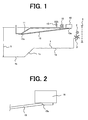
- Figure 1 is a schematic side view of a banknote stacking apparatus which is a preferred embodiment of the present invention.
- a banknote stacking apparatus constitutes a part of a banknote receiving and dispensing machine and is constituted so as to stack those banknotes among banknotes deposited into the banknote receiving and dispensing machine that are discriminated as acceptable banknotes by a banknote discriminating section.
- Bills stacked by the banknote stacking apparatus are deposited in the banknote receiving and dispensing machine once and for all or returned to an operator or a customer in accordance with instructions of the operator or the customer.
- the banknote stacking apparatus is constituted so as to stack substantially horizontally-oriented banknotes vertically and, as shown in Figure 1 , the banknote stacking apparatus according to this preferred embodiment includes a banknote stacking plate 1 for stacking banknotes on the upper surface thereof, a pair of rollers 2 and a vane wheel 3 disposed below the pair of rollers 2 and adapted for scraping off rear end portions of banknotes toward the upper surface of the banknote stacking plate, namely, downwardly.
- a sensor 5 adapted for detecting rear end portions of banknotes and disposed upstream of the vane wheel 3 with respect to a banknote transporting direction.
- a shutter 6 is provided at an outlet portion disposed at the most downstream end portion of the banknote stacking apparatus with respect to the banknote transporting direction.
- the banknote stacking plate 1 includes a first horizontal surface portion 1a extending from a portion in the vicinity of the vane wheel 3 in substantially a horizontal direction, an inclined surface portion 1c extending from the downstream end portion of the first horizontal surface portion 1a obliquely downward and a second horizontal surface portion 1b extending from the downstream end portion of the inclined surface portion 1c in substantially a horizontal direction.
- the banknote stacking apparatus further includes a first banknote press plate 11 whose upstream end portion is firmly fixed to a support shaft 10 so as to be swingable as the support shaft 10 is rotated and which can press banknotes fed onto the banknote stacking plate 1.
- the first banknote press plate 11 includes a main portion parallel with the first horizontal surface portion 1a of the banknote stacking plate 1 when it is positioned at the waiting position thereof, an inclined portion parallel with the inclined surface portion 1c of the banknote stacking plate 1 when it is positioned at the waiting position thereof and a mounting portion mounted on the support shaft 10.
- the first banknote press plate 11 is biased by a tension spring 13 in the clockwise direction about the support shaft 10 so that the main portion of the first banknote press plate 11 is kept substantially horizontal at the waiting position thereof shown in Figure 1 .
- the banknote stacking apparatus further includes a second banknote press plate 15 whose surface in the vicinity of the downstream end portion thereof is firmly fixed to the first banknote press plate 11 and whose surface in the vicinity of the upstream end portion thereof is firmly fixed to a mounting member 16 at a position upstream of the support shaft 10 and on the side toward the banknote stacking plate 1 from the support shaft 10.
- the second banknote press plate 15 is formed of a synthetic resin sheet having flexibility such as a polyethylene terephthalate sheet.
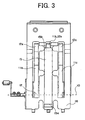
- FIG 2 is a schematic enlarged side view showing details of a portion of the second banknote press plate 15 in the vicinity of the upstream end portion thereof.
- the second banknote press plate 15 is formed with a crease 15a in contact with a portion where the second banknote press plate 15 is firmly fixed to the mounting member 16 and the second banknote press plate 15 is constituted so as to be swingable about the crease 15a.
- the downstream end portion of the second banknote press plate 15 is firmly fixed to the first banknote press plate 11 and is formed with a crease 15b in contact with a portion where the second banknote press plate 15 is firmly fixed to the first banknote press plate 11 so that the second banknote press plate 15 is swingable about the crease 15b.
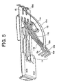
- Figure 3 is a schematic plan view showing the arrangement of the first banknote press plate 11 and the second banknote press plate 15.
- the first banknote press plate 11 includes a base end portion 12 firmly fixed to the support shaft 10 and a substantially a fork-shaped plate member having three teeth 11a, 11b and 11c extending toward a downstream side with respect to the banknote transporting direction and parallel with each other and the downstream end portion of each of the teeth 11a, 11b and 11c of the first banknote press plate 11 constitutes one of press surfaces 12a, 12b and 12c for pressing banknotes fed to above the banknote stacking plate 1 toward the inclined surface portion 1c of the banknote stacking plate 1.
- the surface of the second banknote press plate 15 in the vicinity of the upstream end portion thereof is firmly fixed to the mounting member 16 at a position upstream of the support shaft 10 and on the side toward the banknote stacking plate 1 from the support shaft 10.
- the surface of the second banknote press plate 15 in the vicinity of the downstream end portion thereof is firmly fixed to the press surface 12b of the tooth 11b positioned at a central position among the three teeth 11a, 11b and 11c of the first banknote stacking plate 11.
- the second banknote press plate 15 is formed with a crease 15b in contact with a portion where the second banknote press plate 15 is firmly fixed to the first banknote press plate 11 and the second banknote press plate 15 is constituted so as to be swingable about the crease 15b.
- Figure 4 is a block diagram of an input system, a driving system, a detection system and a control system of the banknote stacking apparatus according to this preferred embodiment.
- an input system of the banknote stacking apparatus includes an input means 20 which is operated by the operator or the customer and through which instruction signals can be input.
- a driving system of the banknote stacking apparatus includes a motor 25 for rotating the vane wheel 3, a solenoid 27 for driving the first banknote press plate 11 and a solenoid 28 for opening and closing the shutter 6.
- a detection system of the banknote stacking apparatus includes a banknote discriminating sensor 30 provided in a banknote transporting passage and adapted for detecting an optical pattern of a banknote and the like and outputting a banknote detection signal and the sensor 5 provided upstream of the vane wheel 3 and adapted for detecting rear end potions of banknotes fed to the banknote stacking plate 1.
- a control system of the banknote stacking apparatus includes a control unit 40 for discriminating, based on a detection signal input from the banknote discriminating sensor 30, whether the banknote detected by the banknote discriminating sensor 30 is an actually circulated genuine banknote and acceptable or an unacceptable banknote such as a counterfeit banknote, a foreign banknote or the like and discriminating the denomination of the banknote when the banknote is acceptable and driving the motor 25 and the solenoid 27 based on a detection signal input from the sensor 5.
- the thus constituted banknote stacking apparatus stacks banknotes on the banknote stacking plate 1 in the following manner.
- the instruction signal is input to the control unit 40 and when the control unit 40 receives the instruction signal from the input means 20, it outputs a drive signal to the motor 25 to rotate the vane wheel 3.
- the first banknote press plate 11 is biased by the tension spring 13 in the clockwise direction and is held at the waiting position thereof apart from the upper surface of the banknote stacking plate 1. Therefore, the second banknote press plate 15 whose surface in the vicinity of the downstream end portion thereof is firmly fixed to the press surface 12b of the central tooth 11b of the first banknote press plate 11 is also held at the waiting position thereof apart from the upper surface of the banknote stacking plate 1.
- banknote discriminating sensor 30 When a banknote deposited into the banknote receiving and dispensing machine is transported in a banknote transporting passage (not shown) and an optical pattern of the banknote and the like is detected by the banknote discriminating sensor 30 provided in the banknote transporting passage, a banknote detection signal is output from the banknote discriminating sensor 30 to the control unit 40.
- control unit 40 judges based on the banknote detection signal input from the banknote discriminating sensor 30 that the banknote detected by the banknote discriminating sensor 30 is acceptable, the control unit 40 feeds the banknote toward the banknote stacking apparatus and the banknote is fed by the pair of rollers 2 to above the banknote stacking plate 1.
- a banknote detection signal is output from the sensor 5 to the control unit 40.
- control unit 40 When the control unit 40 receives the banknote detection signal from the sensor 5, the control unit 40 outputs a drive signal to the solenoid 27 when a predetermined time period has passed after it received the banknote detection signal.
- the solenoid 27 swings the first banknote press plate 11 in the counterclockwise direction in Figure 1 about the support shaft 10 against the spring force of the tension spring 13, whereby the banknote fed above the banknote stacking plate 1 is pressed toward the inclined surface portion 1c of the banknote stacking plate 1 by the press surfaces 12a, 12b, 12c of the teeth 11a, 11b, 11c.
- Figure 5 is a schematic perspective view showing the first banknote press plate 11 and the second banknote press plate 15 when the first banknote press plate 11 is swung about the support shaft 10 in the counterclockwise direction in Figure 1 .
- the surface of the second banknote press plate 15 in the vicinity of the downstream end portion thereof is firmly fixed to the press surface 12b of the tooth 11b of the first banknote press plate 11 and the second banknote press plate 15 is formed with the crease 15b in contact with the portion where the second banknote press plate 15 is firmly fixed to the press surface 12b of the tooth 11b.
- the surface of the second banknote press plate 15 in the vicinity of the upstream end portion thereof is firmly fixed to the mounting member 16 at a position upstream of the support shaft 10 and on the side toward the banknote stacking plate 1 from the support shaft 10 and the second banknote press plate 15 is formed with a crease 15a in contact with the portion where the second banknote press plate 15 is firmly fixed to the mounting member 16. Therefore, when the first banknote press plate 11 is swung counterclockwise about the support shaft 10, as shown in Figure 5 , the second banknote press plate 15 is forcibly swung.
- the distance between the upstream end portion and downstream end portion of the second banknote press plate 15 is shortened and the second banknote press plate 15 formed of a synthetic resin sheet having flexibility such as a polyethylene terephthalate sheet is consequently deformed, whereby a convex portion 15c is formed to project toward the banknote stacking plate 1.
- a portion of the banknote fed to above the banknote stacking plate 1 between the front end portion (downstream end portion) thereof and a portion thereof spaced apart from the front end portion by a distance equal to about one-fifth (1/5) of the length of the banknote is pressed by the first banknote press plate 11 toward the inclined surface portion 1c of the banknote stacking plate 1 and a portion of the banknote fed to above the banknote stacking plate 1 between substantially a center portion of the banknote in the longitudinal direction thereof and the rear end portion (upstream end portion) thereof is pressed by the convex portion 15c of the second banknote press plate 15 produced by the deformation of the second banknote press plate 15 toward the first horizontal surface portion 1a of the banknote stacking plate 1.
- the portion of the banknote fed to above the banknote stacking plate 1 between the front end portion (downstream end portion) thereof and a portion thereof spaced apart from the front end portion by a distance equal to about one-fifth (1/5) of the length of the banknote is pressed by the first banknote press plate 11 toward the inclined surface portion 1c of the banknote stacking plate 1 and the portion of the banknote fed onto the banknote stacking plate 1 between substantially the center portion of the banknote in the longitudinal direction thereof and the rear end portion (upstream end portion) thereof is pressed by the convex portion 15c of the second banknote press plate 15 produced by the deformation of the second banknote press plate 15 formed of a synthetic resin sheet having flexibility toward the first horizontal surface portion 1a.
- the banknote can be stacked on the upper surface of the banknote stacking plate 1 in the desired manner.
- control unit 40 When the banknote has been stacked on the upper surface of the banknote stacking plate 1, the control unit 40 outputs a drive stop signal to the solenoid 27, whereby the solenoid 27 is turned off.
- the first banknote press plate 11 is returned by the spring force of the tension spring 13 to the waiting position thereof shown in Figure 1 and the second banknote press plate 15 whose downstream end portion is firmly fixed to the first banknote press plate 11 is also returned to the waiting position thereof shown in Figure 1 .
- control unit 40 Every time the sensor 5 detects the rear end portion of a banknote and a banknote detection signal is input to the control unit 40, the control unit 40 repeats the same operation and when the control unit 40 judges that all banknotes deposited into the banknote receiving and dispensing machine and discriminated to be acceptable have been fed into the banknote stacking apparatus, the control unit 40 terminates the banknote stacking operation for stacking banknotes in the banknote stacking apparatus.
- the portion of the banknote fed to above the banknote stacking plate 1 between the front end portion (downstream end portion) thereof and a portion thereof spaced apart from the front end portion by a distance equal to about one-fifth (1/5) of the length of the banknote is pressed by the first banknote press plate 11 toward the inclined surface portion 1c of the banknote stacking plate 1 and the portion of the banknote fed to above the banknote stacking plate 1 between substantially the center portion of the banknote in a longitudinal direction thereof and the rear end portion (upstream end portion) thereof is pressed by the convex portion 15c of the second banknote press plate 15 produced by the deformation of the second banknote press plate 15 formed of a synthetic resin sheet having flexibility toward the first horizontal surface portion 1a of the banknote stacking plate 1, so that even in the case where a banknote whose substantially central portion is folded or a banknote whose front end portion is curled upwardly is fed into the banknote stacking apparatus or even in the case where a banknote apt to be very easily folded
- the downstream end portion of the second banknote press plate 15 is firmly fixed to the press surface 12b of the tooth 11b of the first banknote press plate 11, when the solenoid 27 is driven to swing the first banknote press plate 11 about the support shaft 10, the second banknote press plate 15 is simultaneously swung. Therefore, since the first banknote press plate 11 and the second banknote press plate 15 can be swung in the desired manner only by driving the solenoid 27 and the banknotes fed into the banknote stacking apparatus can be stacked on the banknote stacking plate 1 in the desired manner, the structure of the banknote stacking apparatus can be markedly simplified.
- Figure 6 is a schematic side view of a banknote stacking apparatus which is another preferred embodiment of the present invention and Figure 7 is a schematic enlarged side view showing the details of a portion of the second banknote press plate 15 in the vicinity of the upstream end portion thereof.
- a banknote stacking apparatus has the same configuration as that of the banknote stacking apparatus shown in Figures 1 to 5 except that the surface of the second banknote press plate 15 in the vicinity of the upstream end portion thereof is firmly fixed to a mounting member 17 at a position upstream of the support shaft 10 and in a plane parallel with a plane including the main portion of the first banknote press plate 11 located at the waiting position thereof and including the support shaft 10.
- the banknote stacking apparatus is also constituted so that an acceptable banknote is fed by the pair of rollers 2 to above the banknote stacking plate 1 and the rear end portion of the banknote is scraped off by the vane wheel 3 toward the upper surface of the banknote stacking plate 1.
- a banknote detection signal is output from the sensor 5 to the control unit 40.
- the control unit 40 outputs a drive signal to the solenoid 27 when a predetermined time period has passed after it received the banknote detection signal from the sensor 5.
- the first banknote press plate 11 is swung about the support shaft 10 in the counterclockwise direction in Figure 6 against a spring force of the tension spring 13, whereby the banknote fed to above the banknote stacking plate 1 is pressed by the press surfaces 12a, 12b and 12c of the teeth 11a, 11b and 11c toward the inclined surface portion 1c of the banknote stacking plate 1.
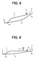
- Figure 8 is a diagram schematically showing the positions of the first banknote stacking plate 11 and the second banknote stacking plate 15 when the first banknote stacking plate 11 is swung about the support shaft 10 in the counterclockwise direction in Figure 6 .
- the second banknote press plate 15 formed of a synthetic resin sheet having flexibility such as a polyethylene terephthalate sheet is deformed convexly toward the banknote stacking plate 1 as the first banknote press plate 11 is swung about the support shaft 10 in the counterclockwise direction, whereby the banknote fed to above the upper surface of the banknote stacking plate 1 is pressed by the first banknote press plate 11 at a portion of the banknote between the front end portion thereof and a portion thereof spaced from the front end portion by a distance equal to about one-fifth (1/5) of the length of the banknote toward the inclined surface portion 1c of the banknote stacking plate 1 and the banknote is pressed by the convex portion 15c of the second banknote press plate 15 at a portion of the banknote between substantially a center portion thereof in the longitudinal direction of the banknote and
- the portion of the banknote fed to above the banknote stacking plate 1 between the front end portion (downstream end portion) thereof and the portion thereof spaced apart from the front end portion by a distance equal to about one-fifth (1/5) of the length of the banknote is pressed by the first banknote press plate 11 toward the inclined surface portion 1c of the banknote stacking plate 1 and the portion of the banknote fed to above the banknote stacking plate 1 between substantially the center portion of the banknote in a longitudinal direction thereof and the rear end portion (upstream end portion) thereof is pressed by the convex portion 15c of the second banknote press plate 15 produced by the deformation of the second banknote press plate 15 formed of a synthetic resin sheet having flexibility toward the first horizontal surface portion 1a of the banknote stacking plate 1, so that even in the case where a banknote whose substantially a central portion is folded or a banknote whose front end portion is curled upwardly is fed into the banknote
- control unit 40 When the banknote has been stacked on the upper surface of the banknote stacking plate 1, the control unit 40 outputs a drive stop signal to the solenoid 27, whereby the solenoid 27 is turned off.
- the first banknote press plate 11 is returned by a spring force of the tension spring 13 to the waiting position thereof shown in Figure 6 and the second banknote press plate 15 whose downstream end portion is firmly fixed to the first banknote press plate 11 is also returned to the waiting position thereof shown in Figure 6 .
- control unit 40 Every time the sensor 5 detects the rear end portion of a banknote and a banknote detection signal is input to the control unit 40, the control unit 40 repeats the same operation and when the control unit 40 judges that all banknotes deposited into the banknote receiving and dispensing machine and discriminated to be acceptable have been fed into the banknote stacking apparatus, the control unit 40 terminates the banknote stacking operation for stacking banknotes in the banknote stacking apparatus.
- the portion of the banknote fed to above the banknote stacking plate 1 between the front end portion (downstream end portion) thereof and a portion thereof spaced apart from the front end portion by a distance equal to about one-fifth (1/5) of the length of the banknote is pressed by the first banknote press plate 11 toward the inclined surface portion 1c of the banknote stacking plate 1 and the portion of the banknote fed to above the banknote stacking plate 1 between substantially the center portion of the banknote in a longitudinal direction thereof and the rear end portion (upstream end portion) thereof is pressed by the convex portion 15c of the second banknote press plate 15 produced by the deformation of the second banknote press plate 15 formed of a synthetic resin sheet having flexibility toward the first horizontal surface portion 1a of the banknote stacking plate 1, so that even in the case where a banknote whose substantially central portion is folded or a banknote whose front end portion is curled upwardly is fed into the banknote stacking apparatus or even in the case where a banknote apt to be very easily folded
- the downstream end portion of the second banknote press plate 15 is firmly fixed to the press surface 12b of the tooth 11b of the first banknote press plate 11, when the solenoid 27 is driven to swing the first banknote press plate 11 about the support shaft 10, the second banknote press plate 15 is simultaneously swung. Therefore, since the first banknote press plate 11 and the second banknote press plate 15 can be swung in the desired manner only by driving the solenoid 27 and the banknotes fed into the banknote stacking apparatus can be stacked on the banknote stacking plate 1 in a desired manner, the structure of the banknote stacking apparatus can be markedly simplified.
- Figure 9 is a schematic side view of a banknote stacking apparatus which is a further preferred embodiment of the present invention.
- a banknote stacking apparatus has the same configuration as that of the banknote stacking apparatus shown in Figures 1 to 5 except that the surface of the second banknote press plate 15 in the vicinity of the upstream portion thereof is firmly fixed to a mounting member 17 at a position upstream of the support shaft 10 and in a plane including the support shaft 10 and the main portion of the first banknote press plate 11.
- the banknote stacking apparatus is also constituted so that an acceptable banknote is fed by the pair of rollers 2 to above the banknote stacking plate 1 and the rear end portion of the banknote is scraped off by the vane wheel 3 toward the upper surface of the banknote stacking plate 1.
- a banknote detection signal is output from the sensor 5 to the control unit 40.
- the control unit 40 outputs a drive signal to the solenoid 27 when a predetermined time period has passed after it received the banknote detection signal from the sensor 5.
- the first banknote press plate 11 is swung about the support shaft 10 in the counterclockwise direction in Figure 6 against a spring force of the tension spring 13, whereby the banknote fed to above the banknote stacking plate 1 is pressed by the press surfaces 12a, 12b and 12c of the teeth 11a, 11b and 11c toward the inclined surface portion 1c of the banknote stacking plate 1.
- Figure 10 is a diagram showing positions and shapes of the first banknote press plate 11 and the second banknote press plate 15 when the first banknote press plate 11 is swung about the support shaft 10 in the counterclockwise direction in Figure 9 .
- the second banknote press plate 15 formed of a synthetic resin sheet having flexibility such as a polyethylene terephthalate sheet is consequently deformed convexly toward the banknote stacking plate 1 as the first banknote press plate 11 is swung about the support shaft 10 in the counterclockwise direction, whereby the banknote fed to above the upper surface of the banknote stacking plate 1 is pressed by the first banknote press plate 11 at a portion of the banknote between the front end portion thereof and a portion thereof spaced from the front end portion by a distance equal to about one-fifth (1/5) of the length of the banknote toward the inclined surface portion 1c of the banknote stacking plate 1 and the banknote is pressed by the convex portion 15c of the second banknote press plate 15 at a portion of the banknote between substantially a center portion thereof in the longitudinal direction of the bank
- the portion of the banknote fed to above the banknote stacking plate 1 between the front end portion (downstream end portion) thereof and the portion thereof spaced apart from the front end portion by a distance equal to about one-fifth (1/5) of the length of the banknote is pressed by the first banknote press plate 11 toward the inclined surface portion 1c of the banknote stacking plate 1 and the portion of the banknote fed to above the banknote stacking plate 1 between substantially the center portion of the banknote in the longitudinal direction thereof and the rear end portion (upstream end portion) thereof is pressed by the convex portion 15c of the second banknote press plate 15 produced by the deformation of the second banknote press plate 15 formed of a synthetic resin sheet having flexibility toward the first horizontal surface portion 1a of the banknote stacking plate 1, so that even in the case where a banknote whose substantially central portion is folded or a banknote whose front end portion is curled upwardly is fed into the banknote stacking apparatus
- control unit 40 When the banknote has been stacked on the upper surface of the banknote stacking plate 1, the control unit 40 outputs a drive stop signal to the solenoid 27, whereby the solenoid 27 is turned off.
- the first banknote press plate 11 is returned by the spring force of the tension spring 13 to the waiting position thereof shown in Figure 6 and the second banknote press plate 15 whose downstream end portion is firmly fixed to the first banknote press plate 11 is also returned to the waiting position thereof shown in Figure 9 .
- control unit 40 Every time the sensor 5 detects the rear end portion of a banknote and a banknote detection signal is input to the control unit 40, the control unit 40 repeats the same operation and when the control unit 40 judges that all banknotes deposited into the banknote receiving and dispensing machine and discriminated to be acceptable have been fed into the banknote stacking apparatus, the control unit 40 terminates the banknote stacking operation for stacking banknotes in the banknote stacking apparatus.
- the portion of the banknote fed to above the banknote stacking plate 1 between the front end portion (downstream end portion) thereof and a portion thereof spaced apart from the front end portion by a distance equal to about one-fifth (1/5) of the length of the banknote is pressed by the first banknote press plate 11 toward the inclined surface portion 1c of the banknote stacking plate 1 and the portion of the banknote fed to above the banknote stacking plate 1 between substantially the center portion of the banknote in a longitudinal direction thereof and the rear end portion (upstream end portion) thereof is pressed by the convex portion 15c of the second banknote press plate 15 produced by the deformation of the second banknote press plate 15 formed of a synthetic resin sheet having flexibility toward the first horizontal surface portion 1a of the banknote stacking plate 1, so that even in the case where a banknote whose substantially central portion is folded or a banknote whose front end portion is curled upwardly is fed into the banknote stacking apparatus or even in the case where a banknote apt to be very easily folded
- the downstream end portion of the second banknote press plate 15 is firmly fixed to the press surface 12b of the tooth 11b of the first banknote press plate 11, when the solenoid 27 is driven to swing the first banknote press plate 11 about the support shaft 10, the second banknote press plate 15 is simultaneously swung. Therefore, since the first banknote press plate 11 and the second banknote press plate 15 can be swung in the desired manner only by driving the solenoid 27 and the banknotes fed into the banknote stacking apparatus can be stacked on the banknote stacking plate 1 in the desired manner, the structure of the banknote stacking apparatus can be markedly simplified.
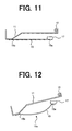
- Figure 11 is a schematic side view of a banknote stacking apparatus which is a further preferred embodiment of the present invention.
- a banknote stacking apparatus has the same configuration as the banknote stacking apparatus shown in Figures 1 to 5 except that the surface of the second banknote press plate 15 in the vicinity of the upstream end portion thereof is firmly fixed to a mounting member 17 secured to the body of the banknote stacking apparatus at a position downstream of the support shaft 10 and on the side toward the banknote stacking plate 1 from a plane parallel with a plane including the main portion of the first banknote press plate 11 and including the support shaft 10.
- the banknote stacking apparatus is also constituted so that an acceptable banknote is fed by the pair of rollers 2 to above the banknote stacking plate 1 and the rear end portion of the banknote is scraped off by the vane wheel 3 toward the upper surface of the banknote stacking plate 1.
- a banknote detection signal is output from the sensor 5 to the control unit 40.
- the control unit 40 outputs a drive signal to the solenoid 27 when a predetermined time period has passed after it received the banknote detection signal from the sensor 5.
- the first banknote press plate 11 is swung about the support shaft 10 in the counterclockwise direction in Figure 6 against a spring force of the tension spring 13, whereby the banknote fed onto the banknote stacking plate 1 is pressed by the press surfaces 12a, 12b and 12c of the teeth 11a, 11b and 11c toward the inclined surface portion 1c of the banknote stacking plate 1.
- Figure 12 is a side view schematically showing the positions and shapes of the first banknote press plate 11 and the second banknote press plate 15 when the first banknote press plate 11 is swung about the support shaft 10 in the counterclockwise direction in Figure 11 .
- the second banknote press plate 15 formed of a synthetic resin sheet having flexibility such as a polyethylene terephthalate sheet is deformed convexly toward the banknote stacking plate 1 as the first banknote press plate 11 is swung about the support shaft 10 in the counterclockwise direction, whereby the banknote fed onto the upper surface of the banknote stacking plate 1 is pressed by the first banknote press plate 11 at a portion of the banknote between the front end portion thereof and a portion spaced from the front end portion thereof by a distance equal to about one-fifth (1/5) of the length of the banknote toward the inclined surface portion 1c of the banknote stacking plate 1 and the banknote is pressed by the convex portion 15c of the second banknote press plate 15 at a portion of the banknote between substantially a center portion thereof in the longitudinal direction of the banknote and the
- the portion of the banknote fed onto the upper surface of the banknote stacking plate 1 between the front end portion (downstream end portion) thereof and the portion thereof spaced apart from the front end portion by a distance equal to about one-fifth (1/5) of the length of the banknote is pressed by the first banknote press plate 11 toward the inclined surface portion 1c of the banknote stacking plate 1 and the portion of the banknote fed onto the banknote stacking plate 1 between substantially the center portion of the banknote in a longitudinal direction thereof and the rear end portion (upstream end portion) thereof is pressed by the convex portion 15c of the second banknote press plate 15 produced by the deformation of the second banknote press plate 15 formed of a synthetic resin sheet having flexibility toward the first horizontal surface portion 1a of the banknote stacking plate 1, so that even in the case where a banknote whose substantially a central portion is folded or a banknote whose front end portion is curled upwardly is fed into the
- the downstream end portion of the second banknote press plate 15 is firmly fixed to the press surface 12b of the tooth 11b of the first banknote press plate 11, when the solenoid 27 is driven to swing the first banknote press plate 11 about the support shaft 10, the second banknote press plate 15 is simultaneously swung. Therefore, since the first banknote press plate 11 and the second banknote press plate 15 can be swung in the desired manner only by driving the solenoid 27 and the banknotes fed into the banknote stacking apparatus can be stacked on the banknote stacking plate 1 in the desired manner, the structure of the banknote stacking apparatus can be markedly simplified.
- control unit 40 When the banknote has been stacked on the upper surface of the banknote stacking plate 1, the control unit 40 outputs a drive stop signal to the solenoid 27, whereby the solenoid 27 is turned off.
- the first banknote press plate 11 is returned by the spring force of the tension spring 13 to the waiting position thereof shown in Figure 6 and the second banknote press plate 15 whose downstream end portion is firmly fixed to the first banknote press plate 11 is also returned to the waiting position thereof shown in Figure 11 .
- control unit 40 Every time the sensor 5 detects the rear end portion of a banknote and a banknote detection signal is input to the control unit 40, the control unit 40 repeats the same operation and when the control unit 40 judges that all banknotes deposited into the banknote receiving and dispensing machine and discriminated to be acceptable have been fed into the banknote stacking apparatus, the control unit 40 terminates the banknote stacking operation for stacking banknotes in the banknote stacking apparatus.
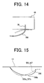
- Figure 13 is a schematic front view showing the arrangement of a first banknote press plate 11 and second banknote press plates 55, 56 and 57 of a banknote stacking apparatus which is a further preferred embodiment of the present invention
- Figure 14 is a diagram schematically showing a portion of a second banknote press plate in the vicinity of an upstream end portion located at a central position of the banknote stacking apparatus shown in Figure 13 .
- three second banknote press plates 55, 56, 57 have the same length and each of the second banknote press plates 55, 56 and 57 is attached to one of the three parallel teeth 11a, 11b and 11c extending from the base end portion 12 of the first banknote stacking plate 11.
- Each of the three second banknote press plates 55, 56 and 57 is firmly fixed to one of the press surfaces 12a, 12b and 12c of the teeth 11a, 11b and 11c of the first banknote press plate 11 at the surface in the vicinity of the downstream end portion thereof and each of the three second banknote press plates 55, 56 and 57 is formed with a crease 55b, 56b, 57b in contact with the portion where it is firmly fixed to one of the press surfaces 12a, 12b and 12c.
- each of the second banknote press plates 55 and 57 disposed on the opposite sides among the three second banknote press plates 55, 56 and 57 is firmly fixed to the mounting member 16 so that the surface in the vicinity of the upstream end portion thereof is firmly fixed to the mounting member 16 at a position upstream of the support shaft 10 and on the side toward the banknote stacking plate 1 from the support shaft 10 and each of the second banknote press plates 55 and 57 is formed with a crease 55a, 57a in contact with the portion where it is firmly fixed to the mounting member 16.
- the upstream end portion of the second banknote press plate 56 disposed at a central portion is inserted into a slit 18 formed in the mounting member 16 upstream of the support shaft 10 and firmly fixed to a linear region on an inner surface of the slit 18.
- the banknote stacking apparatus is also constituted so that a banknote discriminated to be acceptable is fed by the pair of rollers 2 to above the banknote stacking plate 1 and the rear end portion of the banknote is scraped off by the vane wheel 3 toward the upper surface of the banknote stacking plate 1.
- a banknote detection signal is output from the sensor 5 to the control unit 40.
- the control unit 40 outputs a drive signal to the solenoid 27 when a predetermined time period has passed after it received the banknote detection signal from the sensor 5.
- the first banknote press plate 11 is swung about the support shaft 10 in the counterclockwise direction in Figure 1 against the spring force of the tension spring 13, whereby the banknote fed to above the banknote stacking plate 1 is pressed by the press surfaces 12a, 12b and 12c of the teeth 11a, 11b and 11c of the first banknote press plate 11 toward the inclined surface portion 1c of the banknote stacking plate 1.
- Figure 15 is a diagram schematically showing the deformed shape of the second banknote press plate 56 disposed at a central portion and the deformed shapes of the second banknote press plates 55 and 57 disposed on the opposite sides when the solenoid 27 is driven, whereby the first banknote press plate 11 is swung about the support shaft 10 in the counterclockwise direction in Figure 1 against a spring force of the tension spring 13.
- each of the second banknote press plates 55 and 57 in the vicinity of the downstream end portion thereof is firmly fixed to one of the teeth 11a, 11c of the first banknote press plate 11 disposed on the opposite sides and each of the second banknote press plates 55 and 57 is formed with one of the creases 55b, 57b in contact with a portion where the surface in the vicinity of the downstream end portion thereof is firmly fixed to the first banknote press plate 11.
- each of the second banknote press plates 55 and 57 in the vicinity of the upstream end portion thereof is firmly fixed to the mounting member 16 at a position upstream of the support shaft 10 and on the side toward the banknote stacking plate 1 from the support shaft 10 and each of the second banknote press plates 55 and 57 is formed with one of the creases 55a, 57a in contact with a portion where the surface in the vicinity of the upstream end portion thereof is fixed to the mounting member 16.
- each of the second banknote press plates 55 and 57 is deformed in such a manner that the deformed shape of each of the second banknote press plates 55 and 57 is line symmetric with respect to a straight line passing through the center portion thereof in the longitudinal direction and the convex portions 55c, 57c formed in each of the second banknote press plates 55 and 57 becomes maximum at the center portion thereof in the longitudinal direction.
- the surface of the second banknote press plate 56 in the vicinity of the downstream end portion thereof is firmly fixed to the central tooth 11b of the first banknote press plate 11 and the second banknote press plate 56 is formed with a crease 56b in contact with a portion where the surface in the vicinity of the downstream end portion thereof is firmly fixed to the first banknote press plate 11.
- the upstream end portion of the second banknote press plate 56 is inserted into the slit 18 formed in the mounting member 16 at a position upstream of the support shaft 10 and on the side toward the banknote stacking plate 1 from the support shaft 10 and firmly fixed to the inner surface of the slit 18.
- the deformed shape of the second banknote press plate 56 is not line symmetric with respect to a straight line passing through a center portion of the second banknote press plate 56 in the longitudinal direction and the position of the convex portion 56c where the deformation of the second banknote press plate 56 becomes maximum is deviated toward the upstream end portion thereof.
- the second banknote press plates 55, 57 press a portion of the banknote fed to above the banknote stacking plate 1 between substantially the center portion of the banknote in the longitudinal direction thereof and the rear end portion (upstream portion) thereof and relatively closer to the center portion and the second banknote press plate 56 presses a portion of the banknote fed to above the banknote stacking plate 1 between substantially the center portion of the banknote in the longitudinal direction thereof and the rear end portion (upstream portion) thereof and relatively closer to the rear end portion. Therefore, it is possible to stack banknotes fed to above the banknote stacking plate 1 on the banknote stacking plate 1 in the desired manner.
- control unit 40 When the banknote has been stacked on the upper surface of the banknote stacking plate 1, the control unit 40 outputs a drive stop signal to the solenoid 27, whereby the solenoid 27 is turned off.
- the first banknote press plate 11 is returned by the spring force of the tension spring 13 to the waiting position thereof shown in Figure 1 and the second banknote press plates 55, 56, 57 whose downstream end portions are firmly fixed to the first banknote press plate 11 are also returned to the waiting position thereof shown in Figure 1 .
- control unit 40 Every time the sensor 5 detects the rear end portion of a banknote and a banknote detection signal is input to the control unit 40, the control unit 40 repeats the same operation and when the control unit 40 judges that all banknotes deposited into the banknote receiving and dispensing machine and discriminated to be acceptable have been fed into the banknote stacking apparatus, the control unit 40 terminates the banknote stacking operation for stacking banknotes in the banknote stacking apparatus.
- the portion of the banknote fed to above the banknote stacking plate 1 between the front end portion (downstream end portion) thereof and a portion thereof spaced apart from the front end portion by a distance equal to about one-fifth (1/5) of the length of the banknote is pressed by the first banknote press plate 11 toward the inclined surface portion 1c of the banknote stacking plate 1.
- the portion of the banknote fed to above the banknote stacking plate 1 between substantially the center portion of the banknote in the longitudinal direction thereof and the rear end of the banknote is pressed by the second banknote press plates 55 and 57 disposed on the opposite ends toward the first horizontal surface portion 1a of the banknote stacking plate 1 and a portion of the banknote fed to the portion above the banknote stacking plate 1 between substantially the center portion of the banknote in the longitudinal direction thereof and the rear end portion thereof and relatively closer to the rear end portion is pressed by the central second banknote press plate 56 toward the first horizontal surface portion 1a.
- banknotes can be stacked on the upper surface of the banknote stacking plate 1 in the desired manner.
- each of the downstream end portions of the second banknote press plates 55, 56, 57 is firmly fixed to one of the teeth 11a, 11b, 11c of the first banknote press plate 11, when the solenoid 27 is driven to swing the first banknote press plate 11 about the support shaft 10, the second banknote press plates 55, 56, 57 are also swung. Therefore, since not only the first banknote press plate 11 but also the second banknote press plates 55, 56, 57 can be swung only by driving the solenoid 27 and banknotes fed into the banknote stacking apparatus can be stacked on the upper surface of the banknote stacking plate 1 in the banknote stacking apparatus in the desired manner, it is possible to markedly simplify the structure of the banknote stacking apparatus.
- the present invention is not limited to a banknote stacking apparatus for stacking horizontally-oriented banknotes but the present invention can be applied to a banknote stacking apparatus for stacking obliquely-oriented banknotes.
- a synthetic resin sheet having flexibility such as a polyethylene terephthalate sheet
- a synthetic resin sheet having flexibility such as a polyethylene terephthalate sheet
- a thin metal sheet having flexibility can be employed, for example.
- the surface of the second banknote press plate 15 in the vicinity of the upstream end portion thereof is firmly fixed to a mounting member 17 secured to the body of the banknote stacking apparatus at a position downstream of the support shaft 10 and on the side toward the banknote stacking plate 1 from a plane parallel with a plane including the main portion
- the surface of the second banknote press plate 15 in the vicinity of the upstream end portion thereof may be firmly fixed to a mounting member 17 secured to the body of the banknote stacking apparatus at a position downstream of the support shaft 10 and on the side toward the banknote stacking plate 1 from a plane parallel with a plane including the main portion and the support shaft 10.
- the surface of the second banknote press plate 15 formed of a synthetic resin sheet having flexibility such as a polyethylene terephthalate sheet in the vicinity of the upstream end portion thereof is firmly fixed to the mounting member 16 at a position upstream of the support shaft 10 and on the side toward the banknote stacking plate 1 from the support shaft 10, and in the preferred embodiment shown in Figures 6 to 8 , the surface of the second banknote press plate 15 formed of a synthetic resin sheet having flexibility such as a polyethylene terephthalate sheet in the vicinity of the upstream end portion thereof is firmly fixed to the mounting member 17 at a position in the plane parallel with the plane including the main portion of the first banknote press plate 11 positioned at the waiting position thereof and including the support shaft 10 and upstream of the support shaft 10.
- the surface of the second banknote press plate 15 formed of a synthetic resin sheet having flexibility such as a polyethylene terephthalate sheet in the vicinity of the upstream end portion thereof is firmly fixed to the mounting member 17 at a position in the plane including the support shaft 10 and the main portion of the first banknote press plate 11 positioned at the waiting position thereof and, in the preferred embodiment shown in Figures 11 and 12 , the surface of the second banknote press plate 15 formed of a synthetic resin sheet having flexibility such as a polyethylene terephthalate sheet in the vicinity of the upstream end portion thereof is firmly fixed to the mounting member 17 secured to the body of the banknote stacking apparatus at a position downstream of the support shaft 10 and on the side toward the banknote stacking plate 1 from a plane parallel with the plane including the main portion of the first banknote press plate 11 and including the support shaft 10.
- each of the upstream end portions of the second banknote press plates 55, 56, 57 each being formed of a synthetic resin sheet having flexibility such as a polyethylene terephthalate sheet is firmly fixed to the mounting member 16 at a position upstream of the support shaft 10 and on the side toward the banknote stacking plate 1 from the support shaft 10.
- each of the second banknote press plates 15, 55, 56, 57 formed of a synthetic resin sheet having flexibility such as a polyethylene terephthalate sheet is also swung, whereby the distance between the downstream end portion of each of the second banknote press plates 15, 55, 56, 57 mounted on the first banknote press plate 11 and the upstream end portion thereof mounted on the body of the banknote stacking apparatus is shortened and it is not absolutely necessary to firmly fix the surface of the second banknote press plate 15 in the vicinity of the upstream end portion thereof to the mounting member 16 at a position upstream of the support shaft 10 and on the side toward the banknote stacking plate 1 from the support shaft 10, firmly fix the surface of the second banknote press plate 15 in the vicinity of the upstream end portion thereof to the mounting member 17 at a position in the plane parallel with a plane including the main portion of the first banknote press plate 11 positioned at the waiting position thereof and including the support
- the first banknote press plate 11 has a fork-shape and includes the three teeth 11a, 11b, 11c, it is not absolutely necessary for the first banknote press plate 11 to include three teeth 11a, 11b, 11c and the number of the teeth of the first banknote press plate 11 can be arbitrarily determined. Further, it is not absolutely necessary for the first banknote press plate 11 to be fork-shaped and it is possible to form the first banknote press plate 11 of a single flat plate.
- downstream end portion of the second banknote press plate 15 is mounted only on the central tooth 11b of the fork-shaped first banknote press plate 11 in the preferred embodiment shown in Figures 1 to 5 , the preferred embodiment shown in Figures 6 to 8 , the preferred embodiment shown in Figures 9 and 10 and the preferred embodiment shown in Figures 11 and 12 and the downstream end portion of each of the second banknote press plates 55, 56, 57 having the same length is mounted on one of the teeth 11a, 11b, 11c of the fork-shaped first banknote press plate 11 in the preferred embodiment shown in Figures 13 to 15 .
- downstream end portions of only the two second banknote press plates 55 and 57 having the same length may be mounted on the teeth 11a and 11c of the first banknote press plate 11 located on the opposite sides and the number of the second banknote press plates 15, 55, 56, 57 may be determined depending upon physical properties of the banknotes to be stacked.
- each of the surfaces of the three second banknote press plates 55, 56, 57 in the vicinity of the downstream end portions thereof is firmly fixed to one of the teeth 11a, 11b, 11c of the first banknote press plate 11 and each of the second banknote press plates 55, 56, 57 is formed with one of the creases 55b, 56b, 57b in contact with the portion where it is fixed to the first banknote press plate 11.
- each of the surfaces of the second banknote press plates 55, 57 disposed on the opposite sides in the vicinity of the upstream end portions thereof is firmly fixed to the mounting member 16 at a position upstream of the support shaft 10 and on the side toward the first banknote press plate 11 from the support shaft 10 and each of the second banknote press plates 55, 57 is formed with the crease 55a or 57a in contact with the portion where it is firmly fixed to the mounting member 16.
- the upstream end portion of the second banknote press plate 56 disposed at the central portion is inserted into the slit 18 formed in the mounting member 16 at a position upstream of the support shaft 10 and on the side toward the first banknote press plate 11 from the support shaft 10 and is firmly fixed to the inner surface of the slit 18.
- the banknote stacking plate 1 includes the first horizontal surface portion 1a extending substantially horizontally from the portion in the vicinity of the vane wheel 3, the inclined surface portion 1c extending obliquely downward from the downstream end portion of the first horizontal surface portion 1a and the second horizontal surface portion 1b extending substantially horizontally from the downstream end portion of the inclined surface portion 1c and the banknote stacking apparatus is constituted so that the first banknote press plate 11 presses a banknote toward the inclined surface portion 1c and the second banknote press plates 15, 55, 56, 57 press a banknote toward the first horizontal surface portion 1a.
- banknote stacking plate 1 having such a configuration and to constitute so that the first banknote press plate 11 presses a banknote toward the inclined surface portion 1c of the banknote stacking plate 1 and the second banknote press plates 15, 55, 56, 57 press a banknote toward the first horizontal surface portion 1a of the banknote stacking plate 1 and a banknote stacking plate 1 having another configuration such as a flat banknote stacking plate extending only in the horizontal direction can be used instead of the banknote stacking plate 1 including the first horizontal surface portion 1a extending substantially horizontally from the portion in the vicinity of the vane wheel 3, the inclined surface portion 1c extending obliquely downward from the downstream end portion of the first horizontal surface portion 1a and the second horizontal surface portion 1b extending substantially horizontally from the downstream end portion of the inclined surface portion 1c.
- the banknote stacking apparatus is constituted so that the portion of the banknote fed to above the banknote stacking plate 1 between substantially the central portion in the longitudinal direction thereof and the rear end portion (upstream end portion) thereof is pressed toward the banknote stacking plate 1 by the convex portion 15c of the second banknote press plate 15 formed by the deformation of the second banknote press plate 15.
- the banknote stacking apparatus it is not absolutely necessary to constitute the banknote stacking apparatus so that the portion of the banknote between substantially the central portion in the longitudinal direction thereof and the rear end portion (upstream end portion) thereof is pressed toward the banknote stacking plate 1 by the convex portion 15c of the second banknote press plate 15 formed by the deformation of the second banknote press plate 15 and it is possible to constitute the banknote stacking apparatus so that the convex portion 15c of the second banknote press plate 15 formed by the deformation of the second banknote press plate 15 presses a different portion of the banknote by changing the length of the second banknote press plate 15, the position of the first banknote press plate 11 to which the second banknote press plate 15 is fixed, how the second banknote press plate 15 is fixed to the first banknote press plate 11, the portion of the banknote stacking apparatus to which the second banknote press plate 15 is fixed, how the second banknote press plate 15 is fixed to the banknote stacking apparatus and the like.
- the banknote handling machine is adapted for handling a banknote such as a foreign banknote whose size is larger than that of a banknote intended to be stacked in the preferred embodiment shown in Figures 1 to 5
- the preferred embodiment shown in Figures 6 to 8 the preferred embodiment shown in Figures 9 and 10 or the preferred embodiment shown in Figures 11 and 12
- the length of the first banknote press plate 11, the position of the inclined surface portion 1c of the banknote stacking plate 1 to be pressed by the first banknote press plate 11 and the like may be changed depending upon the size of a banknote to be stacked so that the portion of the banknote between the front end portion (downstream end portion) thereof and a portion spaced apart from the front end portion thereof by a distance equal to about one-fifth (1/5) of the length of the banknote can be pressed by first banknote press plate 11, and the length of the second banknote press plate 15, the portion of the first banknote press plate 11 to which the second banknote press plate 15 is fixed, how the second banknote press plate 11
- the banknote stacking apparatus is constituted so that the portion of the banknote fed to above the banknote stacking plate 1 between substantially the center portion of the banknote in the longitudinal direction thereof and the rear end portion (upstream portion) of the banknote and relatively closer to the center portion can be pressed by the second banknote press plates 55, 57 disposed on the opposite sides and the portion of the banknote fed to above the banknote stacking plate 1 between substantially the center portion of the banknote in the longitudinal direction thereof and the rear end portion thereof and relatively closer to the rear end portion (upstream end portion) is pressed by the second banknote press plate 56 disposed at a central portion.
- an arbitrarily portion of the banknote may be pressed by the second banknote press plates 55, 56, 57 by changing the lengths of the second banknote press plates 55, 56, 57, the portions of the first banknote press plate 11 to which the second banknote press plates 55, 57 are fixed, how the second banknote press plates 55, 57 is fixed to the first banknote press plate 11, the portions of the banknote stacking apparatus to which the second banknote press plates 55, 57 are fixed, how the second banknote press plates 55, 57 is fixed to the banknote stacking apparatus, the portion of the first banknote press plate 11 to which the second banknote press plate 56 is fixed, how the second banknote press plate 56 is fixed to the first banknote press plate 11, the portion of the banknote stacking apparatus to which the second banknote press plate 56 is fixed, how the second banknote press plate 56 is fixed to the banknote stacking apparatus or the like.
- the present invention it is possible to provide an apparatus for stacking sheets in the desired manner by means of a simple structure even in the case where a sheet is folded at substantially a central portion thereof, where a sheet is curled at the front end portion thereof, where a sheet can be easily folded or where a sheet is wrinkled.
Landscapes
- Engineering & Computer Science (AREA)
- Mechanical Engineering (AREA)
- Pile Receivers (AREA)
Applications Claiming Priority (1)
| Application Number | Priority Date | Filing Date | Title |
|---|---|---|---|
| JP2009198192 | 2009-08-28 |
Publications (3)
| Publication Number | Publication Date |
|---|---|
| EP2299412A2 true EP2299412A2 (de) | 2011-03-23 |
| EP2299412A3 EP2299412A3 (de) | 2014-11-26 |
| EP2299412B1 EP2299412B1 (de) | 2015-10-14 |
Family
ID=43532630
Family Applications (1)
| Application Number | Title | Priority Date | Filing Date |
|---|---|---|---|
| EP10008812.9A Not-in-force EP2299412B1 (de) | 2009-08-28 | 2010-08-24 | Blattstapelvorrichtung |
Country Status (6)
| Country | Link |
|---|---|
| US (1) | US8083225B2 (de) |
| EP (1) | EP2299412B1 (de) |
| JP (1) | JP5469554B2 (de) |
| KR (1) | KR101080910B1 (de) |
| CN (1) | CN102001546B (de) |
| TW (1) | TWI419084B (de) |
Families Citing this family (6)
| Publication number | Priority date | Publication date | Assignee | Title |
|---|---|---|---|---|
| CN102249111A (zh) * | 2011-04-21 | 2011-11-23 | 广州广电运通金融电子股份有限公司 | 钞票压紧装置 |
| CN103150810B (zh) * | 2013-03-29 | 2015-11-25 | 广州广电运通金融电子股份有限公司 | 纸币处理设备及其出入钞机构 |
| CN103803330B (zh) * | 2014-01-21 | 2016-06-15 | 成都三泰控股集团股份有限公司 | 纸张收集装置 |
| JP6339405B2 (ja) * | 2014-04-28 | 2018-06-06 | キヤノンファインテックニスカ株式会社 | 駆動装置、シート搬送装置及びシート集積装置 |
| EP3230186B1 (de) * | 2014-12-10 | 2019-10-23 | Hewlett-Packard Development Company, L.P. | Stapelzungenvorrichtung, medienstapelvorrichtung und verfahren zum betreiben einer medienstapelvorrichtung |
| CN107393129B (zh) * | 2017-07-20 | 2023-08-11 | 浙江维融电子科技股份有限公司 | 一种配钞系统 |
Citations (2)
| Publication number | Priority date | Publication date | Assignee | Title |
|---|---|---|---|---|
| JP3336210B2 (ja) | 1996-02-29 | 2002-10-21 | ローレルバンクマシン株式会社 | 紙幣処理機 |
| JP2005247524A (ja) | 2004-03-05 | 2005-09-15 | Laurel Seiki Kk | 紙幣処理機 |
Family Cites Families (15)
| Publication number | Priority date | Publication date | Assignee | Title |
|---|---|---|---|---|
| US2991999A (en) * | 1959-01-16 | 1961-07-11 | Royal Mcbee Corp | Record holding device |
| DE2757849A1 (de) * | 1977-12-23 | 1979-06-28 | Agfa Gevaert Ag | Einrichtung zum sammeln und stapeln von fotografischen papierbildern |
| JPH0811655B2 (ja) * | 1993-06-11 | 1996-02-07 | 日本電気株式会社 | 紙葉類集積機構 |
| US5419545A (en) * | 1994-03-10 | 1995-05-30 | Unisys Corporation | High speed document stacking assembly |
| JPH08301503A (ja) * | 1995-04-27 | 1996-11-19 | Ncr Internatl Inc | 冊子収納装置 |
| JP4626902B2 (ja) * | 2000-05-02 | 2011-02-09 | リコーエレメックス株式会社 | シート後処理装置 |
| DE10043393A1 (de) * | 2000-09-04 | 2002-03-14 | Heidelberger Druckmasch Ag | Vorrichtung zur Aufnahme von Blattstapel |
| JP4160362B2 (ja) * | 2002-10-30 | 2008-10-01 | グローリー株式会社 | 集積装置および循環式紙幣入出金機 |
| JP4138722B2 (ja) * | 2004-09-22 | 2008-08-27 | シャープ株式会社 | シート堆積装置 |
| JP4326441B2 (ja) * | 2004-09-27 | 2009-09-09 | マミヤ・オーピー株式会社 | 紙幣処理装置 |
| CN100591601C (zh) * | 2005-08-05 | 2010-02-24 | 光荣株式会社 | 纸页类收纳输出装置 |
| KR100711316B1 (ko) | 2006-02-03 | 2007-04-27 | 노틸러스효성 주식회사 | 지폐류 자동수납처리기의 카세트장치 |
| KR100737130B1 (ko) | 2006-06-30 | 2007-07-06 | 노틸러스효성 주식회사 | 분리가능한 푸쉬플레이트모듈을 갖는 리사이클박스 |
| JP5045164B2 (ja) * | 2007-03-13 | 2012-10-10 | 沖電気工業株式会社 | 紙幣自動入出金機 |
| JP5390164B2 (ja) * | 2008-10-17 | 2014-01-15 | 富士通フロンテック株式会社 | 紙葉類排出集積装置 |
-
2010
- 2010-07-13 JP JP2010158856A patent/JP5469554B2/ja not_active Expired - Fee Related
- 2010-08-24 TW TW099128271A patent/TWI419084B/zh not_active IP Right Cessation
- 2010-08-24 EP EP10008812.9A patent/EP2299412B1/de not_active Not-in-force
- 2010-08-27 CN CN201010267339XA patent/CN102001546B/zh not_active Expired - Fee Related
- 2010-08-27 KR KR1020100083493A patent/KR101080910B1/ko not_active Expired - Fee Related
- 2010-08-27 US US12/869,989 patent/US8083225B2/en not_active Expired - Fee Related
Patent Citations (2)
| Publication number | Priority date | Publication date | Assignee | Title |
|---|---|---|---|---|
| JP3336210B2 (ja) | 1996-02-29 | 2002-10-21 | ローレルバンクマシン株式会社 | 紙幣処理機 |
| JP2005247524A (ja) | 2004-03-05 | 2005-09-15 | Laurel Seiki Kk | 紙幣処理機 |
Also Published As
| Publication number | Publication date |
|---|---|
| CN102001546A (zh) | 2011-04-06 |
| HK1152695A1 (en) | 2012-03-09 |
| EP2299412A3 (de) | 2014-11-26 |
| JP5469554B2 (ja) | 2014-04-16 |
| EP2299412B1 (de) | 2015-10-14 |
| TW201115509A (en) | 2011-05-01 |
| TWI419084B (zh) | 2013-12-11 |
| US8083225B2 (en) | 2011-12-27 |
| KR101080910B1 (ko) | 2011-11-08 |
| KR20110023810A (ko) | 2011-03-08 |
| CN102001546B (zh) | 2013-09-11 |
| US20110049797A1 (en) | 2011-03-03 |
| JP2011068495A (ja) | 2011-04-07 |
Similar Documents
| Publication | Publication Date | Title |
|---|---|---|
| JP5184104B2 (ja) | 紙葉類処理装置 | |
| EP2299412B1 (de) | Blattstapelvorrichtung | |
| JP5191035B2 (ja) | 紙葉類処理装置 | |
| JPH09237365A (ja) | 紙幣処理機 | |
| JPH09237371A (ja) | 紙幣処理機 | |
| JP5184062B2 (ja) | 紙葉類処理装置 | |
| JPH09237366A (ja) | 紙幣処理機 | |
| JP5164255B2 (ja) | 紙葉処理装置 | |
| JP5091619B2 (ja) | 紙幣処理装置 | |
| JP2773497B2 (ja) | 紙葉類厚さ検出機構 | |
| JP5608814B2 (ja) | 紙葉類識別装置 | |
| JP5791464B2 (ja) | 紙幣保留分離機構とこれを用いた還流式紙幣処理装置 | |
| JP4049476B2 (ja) | 紙葉搬送装置 | |
| HK1152695B (en) | Sheet stacking apparatus | |
| JP5091593B2 (ja) | 紙幣処理装置 | |
| JP4419328B2 (ja) | 紙幣識別機の紙幣収納装置 | |
| WO2025108345A1 (zh) | 纸币集积装置、现金循环处理设备和纸币集积控制方法 | |
| WO2010004845A1 (ja) | 媒体収納操出装置 | |
| JP2002163702A (ja) | 紙幣識別機の紙幣収納装置 | |
| JP2755727B2 (ja) | 紙葉類集積装置 | |
| JP3384607B2 (ja) | 紙葉類収納装置 | |
| JP3545242B2 (ja) | 集積紙幣搬送装置 | |
| JPH09235045A (ja) | 紙幣処理機 | |
| JP2007018147A (ja) | 紙幣集積装置及び取引処理装置 |
Legal Events
| Date | Code | Title | Description |
|---|---|---|---|
| PUAI | Public reference made under article 153(3) epc to a published international application that has entered the european phase |
Free format text: ORIGINAL CODE: 0009012 |
|
| AK | Designated contracting states |
Kind code of ref document: A2 Designated state(s): AL AT BE BG CH CY CZ DE DK EE ES FI FR GB GR HR HU IE IS IT LI LT LU LV MC MK MT NL NO PL PT RO SE SI SK SM TR |
|
| AX | Request for extension of the european patent |
Extension state: BA ME RS |
|
| PUAL | Search report despatched |
Free format text: ORIGINAL CODE: 0009013 |
|
| AK | Designated contracting states |
Kind code of ref document: A3 Designated state(s): AL AT BE BG CH CY CZ DE DK EE ES FI FR GB GR HR HU IE IS IT LI LT LU LV MC MK MT NL NO PL PT RO SE SI SK SM TR |
|
| AX | Request for extension of the european patent |
Extension state: BA ME RS |
|
| RIC1 | Information provided on ipc code assigned before grant |
Ipc: G07D 11/00 20060101AFI20141022BHEP Ipc: B65H 29/52 20060101ALI20141022BHEP Ipc: B65H 31/26 20060101ALI20141022BHEP Ipc: B65H 31/02 20060101ALI20141022BHEP |
|
| 17P | Request for examination filed |
Effective date: 20150428 |
|
| RBV | Designated contracting states (corrected) |
Designated state(s): AL AT BE BG CH CY CZ DE DK EE ES FI FR GB GR HR HU IE IS IT LI LT LU LV MC MK MT NL NO PL PT RO SE SI SK SM TR |
|
| GRAP | Despatch of communication of intention to grant a patent |
Free format text: ORIGINAL CODE: EPIDOSNIGR1 |
|
| INTG | Intention to grant announced |
Effective date: 20150616 |
|
| GRAS | Grant fee paid |
Free format text: ORIGINAL CODE: EPIDOSNIGR3 |
|
| GRAA | (expected) grant |
Free format text: ORIGINAL CODE: 0009210 |
|
| AK | Designated contracting states |
Kind code of ref document: B1 Designated state(s): AL AT BE BG CH CY CZ DE DK EE ES FI FR GB GR HR HU IE IS IT LI LT LU LV MC MK MT NL NO PL PT RO SE SI SK SM TR |
|
| REG | Reference to a national code |
Ref country code: GB Ref legal event code: FG4D |
|
| REG | Reference to a national code |
Ref country code: AT Ref legal event code: REF Ref document number: 755634 Country of ref document: AT Kind code of ref document: T Effective date: 20151015 Ref country code: CH Ref legal event code: EP |
|
| REG | Reference to a national code |
Ref country code: IE Ref legal event code: FG4D |
|
| REG | Reference to a national code |
Ref country code: DE Ref legal event code: R096 Ref document number: 602010028172 Country of ref document: DE |
|
| REG | Reference to a national code |
Ref country code: NL Ref legal event code: MP Effective date: 20151014 |
|
| REG | Reference to a national code |
Ref country code: LT Ref legal event code: MG4D |
|
| REG | Reference to a national code |
Ref country code: AT Ref legal event code: MK05 Ref document number: 755634 Country of ref document: AT Kind code of ref document: T Effective date: 20151014 |
|
| PG25 | Lapsed in a contracting state [announced via postgrant information from national office to epo] |
Ref country code: NO Free format text: LAPSE BECAUSE OF FAILURE TO SUBMIT A TRANSLATION OF THE DESCRIPTION OR TO PAY THE FEE WITHIN THE PRESCRIBED TIME-LIMIT Effective date: 20160114 Ref country code: NL Free format text: LAPSE BECAUSE OF FAILURE TO SUBMIT A TRANSLATION OF THE DESCRIPTION OR TO PAY THE FEE WITHIN THE PRESCRIBED TIME-LIMIT Effective date: 20151014 Ref country code: LT Free format text: LAPSE BECAUSE OF FAILURE TO SUBMIT A TRANSLATION OF THE DESCRIPTION OR TO PAY THE FEE WITHIN THE PRESCRIBED TIME-LIMIT Effective date: 20151014 Ref country code: IS Free format text: LAPSE BECAUSE OF FAILURE TO SUBMIT A TRANSLATION OF THE DESCRIPTION OR TO PAY THE FEE WITHIN THE PRESCRIBED TIME-LIMIT Effective date: 20160214 Ref country code: ES Free format text: LAPSE BECAUSE OF FAILURE TO SUBMIT A TRANSLATION OF THE DESCRIPTION OR TO PAY THE FEE WITHIN THE PRESCRIBED TIME-LIMIT Effective date: 20151014 Ref country code: HR Free format text: LAPSE BECAUSE OF FAILURE TO SUBMIT A TRANSLATION OF THE DESCRIPTION OR TO PAY THE FEE WITHIN THE PRESCRIBED TIME-LIMIT Effective date: 20151014 Ref country code: IT Free format text: LAPSE BECAUSE OF FAILURE TO SUBMIT A TRANSLATION OF THE DESCRIPTION OR TO PAY THE FEE WITHIN THE PRESCRIBED TIME-LIMIT Effective date: 20151014 |
|
| PG25 | Lapsed in a contracting state [announced via postgrant information from national office to epo] |
Ref country code: FI Free format text: LAPSE BECAUSE OF FAILURE TO SUBMIT A TRANSLATION OF THE DESCRIPTION OR TO PAY THE FEE WITHIN THE PRESCRIBED TIME-LIMIT Effective date: 20151014 Ref country code: PT Free format text: LAPSE BECAUSE OF FAILURE TO SUBMIT A TRANSLATION OF THE DESCRIPTION OR TO PAY THE FEE WITHIN THE PRESCRIBED TIME-LIMIT Effective date: 20160215 Ref country code: GR Free format text: LAPSE BECAUSE OF FAILURE TO SUBMIT A TRANSLATION OF THE DESCRIPTION OR TO PAY THE FEE WITHIN THE PRESCRIBED TIME-LIMIT Effective date: 20160115 Ref country code: LV Free format text: LAPSE BECAUSE OF FAILURE TO SUBMIT A TRANSLATION OF THE DESCRIPTION OR TO PAY THE FEE WITHIN THE PRESCRIBED TIME-LIMIT Effective date: 20151014 Ref country code: PL Free format text: LAPSE BECAUSE OF FAILURE TO SUBMIT A TRANSLATION OF THE DESCRIPTION OR TO PAY THE FEE WITHIN THE PRESCRIBED TIME-LIMIT Effective date: 20151014 Ref country code: SE Free format text: LAPSE BECAUSE OF FAILURE TO SUBMIT A TRANSLATION OF THE DESCRIPTION OR TO PAY THE FEE WITHIN THE PRESCRIBED TIME-LIMIT Effective date: 20151014 Ref country code: AT Free format text: LAPSE BECAUSE OF FAILURE TO SUBMIT A TRANSLATION OF THE DESCRIPTION OR TO PAY THE FEE WITHIN THE PRESCRIBED TIME-LIMIT Effective date: 20151014 |
|
| REG | Reference to a national code |
Ref country code: FR Ref legal event code: PLFP Year of fee payment: 7 |
|
| REG | Reference to a national code |
Ref country code: DE Ref legal event code: R097 Ref document number: 602010028172 Country of ref document: DE |
|
| PG25 | Lapsed in a contracting state [announced via postgrant information from national office to epo] |
Ref country code: CZ Free format text: LAPSE BECAUSE OF FAILURE TO SUBMIT A TRANSLATION OF THE DESCRIPTION OR TO PAY THE FEE WITHIN THE PRESCRIBED TIME-LIMIT Effective date: 20151014 |
|
| PLBE | No opposition filed within time limit |
Free format text: ORIGINAL CODE: 0009261 |
|
| STAA | Information on the status of an ep patent application or granted ep patent |
Free format text: STATUS: NO OPPOSITION FILED WITHIN TIME LIMIT |
|
| PG25 | Lapsed in a contracting state [announced via postgrant information from national office to epo] |
Ref country code: RO Free format text: LAPSE BECAUSE OF FAILURE TO SUBMIT A TRANSLATION OF THE DESCRIPTION OR TO PAY THE FEE WITHIN THE PRESCRIBED TIME-LIMIT Effective date: 20151014 Ref country code: SK Free format text: LAPSE BECAUSE OF FAILURE TO SUBMIT A TRANSLATION OF THE DESCRIPTION OR TO PAY THE FEE WITHIN THE PRESCRIBED TIME-LIMIT Effective date: 20151014 Ref country code: EE Free format text: LAPSE BECAUSE OF FAILURE TO SUBMIT A TRANSLATION OF THE DESCRIPTION OR TO PAY THE FEE WITHIN THE PRESCRIBED TIME-LIMIT Effective date: 20151014 Ref country code: SM Free format text: LAPSE BECAUSE OF FAILURE TO SUBMIT A TRANSLATION OF THE DESCRIPTION OR TO PAY THE FEE WITHIN THE PRESCRIBED TIME-LIMIT Effective date: 20151014 Ref country code: DK Free format text: LAPSE BECAUSE OF FAILURE TO SUBMIT A TRANSLATION OF THE DESCRIPTION OR TO PAY THE FEE WITHIN THE PRESCRIBED TIME-LIMIT Effective date: 20151014 |
|
| 26N | No opposition filed |
Effective date: 20160715 |
|
| PG25 | Lapsed in a contracting state [announced via postgrant information from national office to epo] |
Ref country code: SI Free format text: LAPSE BECAUSE OF FAILURE TO SUBMIT A TRANSLATION OF THE DESCRIPTION OR TO PAY THE FEE WITHIN THE PRESCRIBED TIME-LIMIT Effective date: 20151014 |
|
| PG25 | Lapsed in a contracting state [announced via postgrant information from national office to epo] |
Ref country code: BE Free format text: LAPSE BECAUSE OF FAILURE TO SUBMIT A TRANSLATION OF THE DESCRIPTION OR TO PAY THE FEE WITHIN THE PRESCRIBED TIME-LIMIT Effective date: 20151014 |
|
| PG25 | Lapsed in a contracting state [announced via postgrant information from national office to epo] |
Ref country code: MC Free format text: LAPSE BECAUSE OF FAILURE TO SUBMIT A TRANSLATION OF THE DESCRIPTION OR TO PAY THE FEE WITHIN THE PRESCRIBED TIME-LIMIT Effective date: 20151014 |
|
| REG | Reference to a national code |
Ref country code: CH Ref legal event code: PL |
|
| PG25 | Lapsed in a contracting state [announced via postgrant information from national office to epo] |
Ref country code: LI Free format text: LAPSE BECAUSE OF NON-PAYMENT OF DUE FEES Effective date: 20160831 Ref country code: CH Free format text: LAPSE BECAUSE OF NON-PAYMENT OF DUE FEES Effective date: 20160831 |
|
| REG | Reference to a national code |
Ref country code: FR Ref legal event code: PLFP Year of fee payment: 8 |
|
| REG | Reference to a national code |
Ref country code: IE Ref legal event code: MM4A |
|
| PG25 | Lapsed in a contracting state [announced via postgrant information from national office to epo] |
Ref country code: IE Free format text: LAPSE BECAUSE OF NON-PAYMENT OF DUE FEES Effective date: 20160824 |
|
| PG25 | Lapsed in a contracting state [announced via postgrant information from national office to epo] |
Ref country code: LU Free format text: LAPSE BECAUSE OF NON-PAYMENT OF DUE FEES Effective date: 20160824 |
|
| REG | Reference to a national code |
Ref country code: FR Ref legal event code: PLFP Year of fee payment: 9 |
|
| PG25 | Lapsed in a contracting state [announced via postgrant information from national office to epo] |
Ref country code: CY Free format text: LAPSE BECAUSE OF FAILURE TO SUBMIT A TRANSLATION OF THE DESCRIPTION OR TO PAY THE FEE WITHIN THE PRESCRIBED TIME-LIMIT Effective date: 20151014 Ref country code: HU Free format text: LAPSE BECAUSE OF FAILURE TO SUBMIT A TRANSLATION OF THE DESCRIPTION OR TO PAY THE FEE WITHIN THE PRESCRIBED TIME-LIMIT; INVALID AB INITIO Effective date: 20100824 |
|
| PG25 | Lapsed in a contracting state [announced via postgrant information from national office to epo] |
Ref country code: TR Free format text: LAPSE BECAUSE OF FAILURE TO SUBMIT A TRANSLATION OF THE DESCRIPTION OR TO PAY THE FEE WITHIN THE PRESCRIBED TIME-LIMIT Effective date: 20151014 Ref country code: MT Free format text: LAPSE BECAUSE OF NON-PAYMENT OF DUE FEES Effective date: 20160831 Ref country code: MK Free format text: LAPSE BECAUSE OF FAILURE TO SUBMIT A TRANSLATION OF THE DESCRIPTION OR TO PAY THE FEE WITHIN THE PRESCRIBED TIME-LIMIT Effective date: 20151014 |
|
| PG25 | Lapsed in a contracting state [announced via postgrant information from national office to epo] |
Ref country code: BG Free format text: LAPSE BECAUSE OF FAILURE TO SUBMIT A TRANSLATION OF THE DESCRIPTION OR TO PAY THE FEE WITHIN THE PRESCRIBED TIME-LIMIT Effective date: 20151014 |
|
| PG25 | Lapsed in a contracting state [announced via postgrant information from national office to epo] |
Ref country code: AL Free format text: LAPSE BECAUSE OF FAILURE TO SUBMIT A TRANSLATION OF THE DESCRIPTION OR TO PAY THE FEE WITHIN THE PRESCRIBED TIME-LIMIT Effective date: 20151014 |
|
| PGFP | Annual fee paid to national office [announced via postgrant information from national office to epo] |
Ref country code: FR Payment date: 20190524 Year of fee payment: 10 |
|
| PGFP | Annual fee paid to national office [announced via postgrant information from national office to epo] |
Ref country code: DE Payment date: 20190828 Year of fee payment: 10 |
|
| PGFP | Annual fee paid to national office [announced via postgrant information from national office to epo] |
Ref country code: GB Payment date: 20190827 Year of fee payment: 10 |
|
| REG | Reference to a national code |
Ref country code: DE Ref legal event code: R119 Ref document number: 602010028172 Country of ref document: DE |
|
| GBPC | Gb: european patent ceased through non-payment of renewal fee |
Effective date: 20200824 |
|
| PG25 | Lapsed in a contracting state [announced via postgrant information from national office to epo] |
Ref country code: DE Free format text: LAPSE BECAUSE OF NON-PAYMENT OF DUE FEES Effective date: 20210302 Ref country code: FR Free format text: LAPSE BECAUSE OF NON-PAYMENT OF DUE FEES Effective date: 20200831 |
|
| PG25 | Lapsed in a contracting state [announced via postgrant information from national office to epo] |
Ref country code: GB Free format text: LAPSE BECAUSE OF NON-PAYMENT OF DUE FEES Effective date: 20200824 |