EP2297827B1 - Augensichere beleuchtung auf laserbasis - Google Patents
Augensichere beleuchtung auf laserbasis Download PDFInfo
- Publication number
- EP2297827B1 EP2297827B1 EP09786488A EP09786488A EP2297827B1 EP 2297827 B1 EP2297827 B1 EP 2297827B1 EP 09786488 A EP09786488 A EP 09786488A EP 09786488 A EP09786488 A EP 09786488A EP 2297827 B1 EP2297827 B1 EP 2297827B1
- Authority
- EP
- European Patent Office
- Prior art keywords
- laser
- light
- converted
- output
- safe
- Prior art date
- Legal status (The legal status is an assumption and is not a legal conclusion. Google has not performed a legal analysis and makes no representation as to the accuracy of the status listed.)
- Active
Links
Images

Classifications
-
- F—MECHANICAL ENGINEERING; LIGHTING; HEATING; WEAPONS; BLASTING
- F21—LIGHTING
- F21K—NON-ELECTRIC LIGHT SOURCES USING LUMINESCENCE; LIGHT SOURCES USING ELECTROCHEMILUMINESCENCE; LIGHT SOURCES USING CHARGES OF COMBUSTIBLE MATERIAL; LIGHT SOURCES USING SEMICONDUCTOR DEVICES AS LIGHT-GENERATING ELEMENTS; LIGHT SOURCES NOT OTHERWISE PROVIDED FOR
- F21K9/00—Light sources using semiconductor devices as light-generating elements, e.g. using light-emitting diodes [LED] or lasers
- F21K9/60—Optical arrangements integrated in the light source, e.g. for improving the colour rendering index or the light extraction
- F21K9/64—Optical arrangements integrated in the light source, e.g. for improving the colour rendering index or the light extraction using wavelength conversion means distinct or spaced from the light-generating element, e.g. a remote phosphor layer
-
- F—MECHANICAL ENGINEERING; LIGHTING; HEATING; WEAPONS; BLASTING
- F21—LIGHTING
- F21S—NON-PORTABLE LIGHTING DEVICES; SYSTEMS THEREOF; VEHICLE LIGHTING DEVICES SPECIALLY ADAPTED FOR VEHICLE EXTERIORS
- F21S41/00—Illuminating devices specially adapted for vehicle exteriors, e.g. headlamps
- F21S41/10—Illuminating devices specially adapted for vehicle exteriors, e.g. headlamps characterised by the light source
- F21S41/14—Illuminating devices specially adapted for vehicle exteriors, e.g. headlamps characterised by the light source characterised by the type of light source
- F21S41/16—Laser light sources
-
- F—MECHANICAL ENGINEERING; LIGHTING; HEATING; WEAPONS; BLASTING
- F21—LIGHTING
- F21S—NON-PORTABLE LIGHTING DEVICES; SYSTEMS THEREOF; VEHICLE LIGHTING DEVICES SPECIALLY ADAPTED FOR VEHICLE EXTERIORS
- F21S45/00—Arrangements within vehicle lighting devices specially adapted for vehicle exteriors, for purposes other than emission or distribution of light
- F21S45/70—Prevention of harmful light leakage
-
- F—MECHANICAL ENGINEERING; LIGHTING; HEATING; WEAPONS; BLASTING
- F21—LIGHTING
- F21V—FUNCTIONAL FEATURES OR DETAILS OF LIGHTING DEVICES OR SYSTEMS THEREOF; STRUCTURAL COMBINATIONS OF LIGHTING DEVICES WITH OTHER ARTICLES, NOT OTHERWISE PROVIDED FOR
- F21V23/00—Arrangement of electric circuit elements in or on lighting devices
- F21V23/04—Arrangement of electric circuit elements in or on lighting devices the elements being switches
- F21V23/0442—Arrangement of electric circuit elements in or on lighting devices the elements being switches activated by means of a sensor, e.g. motion or photodetectors
- F21V23/0457—Arrangement of electric circuit elements in or on lighting devices the elements being switches activated by means of a sensor, e.g. motion or photodetectors the sensor sensing the operating status of the lighting device, e.g. to detect failure of a light source or to provide feedback to the device
-
- F—MECHANICAL ENGINEERING; LIGHTING; HEATING; WEAPONS; BLASTING
- F21—LIGHTING
- F21V—FUNCTIONAL FEATURES OR DETAILS OF LIGHTING DEVICES OR SYSTEMS THEREOF; STRUCTURAL COMBINATIONS OF LIGHTING DEVICES WITH OTHER ARTICLES, NOT OTHERWISE PROVIDED FOR
- F21V25/00—Safety devices structurally associated with lighting devices
- F21V25/02—Safety devices structurally associated with lighting devices coming into action when lighting device is disturbed, dismounted, or broken
-
- H—ELECTRICITY
- H01—ELECTRIC ELEMENTS
- H01S—DEVICES USING THE PROCESS OF LIGHT AMPLIFICATION BY STIMULATED EMISSION OF RADIATION [LASER] TO AMPLIFY OR GENERATE LIGHT; DEVICES USING STIMULATED EMISSION OF ELECTROMAGNETIC RADIATION IN WAVE RANGES OTHER THAN OPTICAL
- H01S5/00—Semiconductor lasers
- H01S5/005—Optical components external to the laser cavity, specially adapted therefor, e.g. for homogenisation or merging of the beams or for manipulating laser pulses, e.g. pulse shaping
- H01S5/0078—Optical components external to the laser cavity, specially adapted therefor, e.g. for homogenisation or merging of the beams or for manipulating laser pulses, e.g. pulse shaping for frequency filtering
-
- H—ELECTRICITY
- H01—ELECTRIC ELEMENTS
- H01S—DEVICES USING THE PROCESS OF LIGHT AMPLIFICATION BY STIMULATED EMISSION OF RADIATION [LASER] TO AMPLIFY OR GENERATE LIGHT; DEVICES USING STIMULATED EMISSION OF ELECTROMAGNETIC RADIATION IN WAVE RANGES OTHER THAN OPTICAL
- H01S5/00—Semiconductor lasers
- H01S5/005—Optical components external to the laser cavity, specially adapted therefor, e.g. for homogenisation or merging of the beams or for manipulating laser pulses, e.g. pulse shaping
- H01S5/0087—Optical components external to the laser cavity, specially adapted therefor, e.g. for homogenisation or merging of the beams or for manipulating laser pulses, e.g. pulse shaping for illuminating phosphorescent or fluorescent materials, e.g. using optical arrangements specifically adapted for guiding or shaping laser beams illuminating these materials
-
- H—ELECTRICITY
- H01—ELECTRIC ELEMENTS
- H01S—DEVICES USING THE PROCESS OF LIGHT AMPLIFICATION BY STIMULATED EMISSION OF RADIATION [LASER] TO AMPLIFY OR GENERATE LIGHT; DEVICES USING STIMULATED EMISSION OF ELECTROMAGNETIC RADIATION IN WAVE RANGES OTHER THAN OPTICAL
- H01S5/00—Semiconductor lasers
- H01S5/06—Arrangements for controlling the laser output parameters, e.g. by operating on the active medium
- H01S5/068—Stabilisation of laser output parameters
- H01S5/06825—Protecting the laser, e.g. during switch-on/off, detection of malfunctioning or degradation
-
- H—ELECTRICITY
- H01—ELECTRIC ELEMENTS
- H01S—DEVICES USING THE PROCESS OF LIGHT AMPLIFICATION BY STIMULATED EMISSION OF RADIATION [LASER] TO AMPLIFY OR GENERATE LIGHT; DEVICES USING STIMULATED EMISSION OF ELECTROMAGNETIC RADIATION IN WAVE RANGES OTHER THAN OPTICAL
- H01S5/00—Semiconductor lasers
- H01S5/06—Arrangements for controlling the laser output parameters, e.g. by operating on the active medium
- H01S5/068—Stabilisation of laser output parameters
- H01S5/0683—Stabilisation of laser output parameters by monitoring the optical output parameters
-
- F—MECHANICAL ENGINEERING; LIGHTING; HEATING; WEAPONS; BLASTING
- F21—LIGHTING
- F21Y—INDEXING SCHEME ASSOCIATED WITH SUBCLASSES F21K, F21L, F21S and F21V, RELATING TO THE FORM OR THE KIND OF THE LIGHT SOURCES OR OF THE COLOUR OF THE LIGHT EMITTED
- F21Y2115/00—Light-generating elements of semiconductor light sources
- F21Y2115/30—Semiconductor lasers
-
- H—ELECTRICITY
- H01—ELECTRIC ELEMENTS
- H01S—DEVICES USING THE PROCESS OF LIGHT AMPLIFICATION BY STIMULATED EMISSION OF RADIATION [LASER] TO AMPLIFY OR GENERATE LIGHT; DEVICES USING STIMULATED EMISSION OF ELECTROMAGNETIC RADIATION IN WAVE RANGES OTHER THAN OPTICAL
- H01S5/00—Semiconductor lasers
- H01S5/06—Arrangements for controlling the laser output parameters, e.g. by operating on the active medium
- H01S5/068—Stabilisation of laser output parameters
- H01S5/06808—Stabilisation of laser output parameters by monitoring the electrical laser parameters, e.g. voltage or current
Definitions
- the invention relates to the field of a laser-based light source and a method of operating the same, and especially to eye-safe laser-based lighting.
- LEDs Light Emitting Diodes
- Technological breakthroughs in high-power LEDs have opened the door to new lighting concepts driven by miniaturization, lifetime, efficiency and sustainability.
- lasers Compared to LEDs, the advantage of lasers is their much higher brightness. Semiconductor lasers have started to become available in output powers of several Watts, thus enabling a high lumen output. Laser light by itself will not be of much use for illumination since the laser beam is too bright to be eye-safe, too monochromatic for faithful colour reproduction and will result in annoying speckle due to its coherence. A convenient way to resolve these issues is to produce a light source by converting part of the laser light into broadband light via phosphor conversion.
- a blue emitter is combined with a yellow-light emitting phosphor.
- a blue emitter By pumping the yellow phosphor with blue light, part of the blue light is converted into broadband yellow light. This yellow light in combination with the remaining blue light renders white light.
- the colour temperature can be tuned by tuning the phosphor composition and by tuning the ratio of phosphor converted light and remaining blue pump light.
- a blue light emitting laser diode can be used to pump a yellow phosphor to generate white light.
- a near-UV diode laser can be used to pump a phosphor that emits white light or light of a specific colour.
- a red or near-IR laser diode in combination with an upconversion phosphor to generate white light or light of a specific colour.
- Such laser-based light sources relying on phosphor conversion have the advantage that they can be much brighter than the brightness achievable with LEDs: with a laser one can achieve a much higher optical power density at the phosphor than with LEDs.
- Such light sources are ideal for automotive headlamps and spot-lights.
- one critical issue with laser-based lighting is the fact that the light source should adhere to strict legislation and be eye-safe under all circumstances, even when tampered with.
- a laser-based light source comprising
- the invention is applicable for different types of light-conversion devices.
- light-conversion devices phosphors as described above, but also upconversion materials, are preferred, i.e. devices which convert the light to light of another wavelength.
- materials that do not alter the wavelength but the beam properties e.g. scattering devices, are preferred.
- scattering devices are preferred.
- a scattering device is advantageous, since this allows reducing the coherence of the beam and, thus, reduces speckle.
- the invention is based on monitoring a signal being correlated with the laser output and a signal being correlated with the amount of converted light.
- the correlation between the signals and the laser output and/or the amount of converted light may be linear, exponential, logarithmic or the like.
- the operation of the laser-based light source is automatically adapted accordingly.
- the laser-output sensor is formed by a laser-light photodiode adapted for receiving at least a part of the laser light.
- a beam splitter in order to direct a part of the laser light emitted by the laser device to the laser-light photodiode.
- the laser-output sensor is preferably formed by a laser driving current monitor adapted for monitoring the laser driving current. With respect to this, it is especially preferred to monitor the laser driving current, which is typically proportional to a laser output, apart from a threshold current.
- the converted-light sensor is adapted to receive at least a part of the converted light.
- the converted light sensor may be a photodiode or the like. For that reason, preferably light emitted by the light-conversion device in a direction back to the laser is used. Further, it is preferred to use a beam splitter, preferably the same beam splitter as used for the laser light, in order to direct part of the light emitted by the light-conversion device to the converted-light sensor.
- the laser light can be directly coupled into the light-conversion device.
- at least one optical fiber is provided which is adapted for guiding the laser light to the light-convcrsion device. This makes it possible to place the light-conversion device at a greater distance from the laser device.
- an optical fiber is provided which is adapted for guiding at least part of the converted light in a direction back from the light-conversion device to the converted-light sensor.
- the same optical fiber can be used for guiding the light to the light-conversion device and back, or a separate return fiber can be used for the way back.
- a single fiber or a plurality of fibers can be used to form a fiber.
- the converted-light sensor can be arranged at different positions. According to a preferred embodiment of the invention, the converted-light sensor is arranged at the end of the fiber which is remote from the light-conversion device. Alternatively, according to a preferred embodiment of the invention, the converted-light sensor is arranged at a position along the fiber, and an outcoupling device is provided for coupling the converted light out of the fiber and into the converted-light sensor. Furthermore, it is preferred to tap laser light at at least one point along the fiber and guide this light to a remote light-conversion device.
- the optical fiber is provided with electrical wiring for detecting damage of the optical fiber.
- electrical wiring for detecting damage of the optical fiber.
- conducting wires are wound around the optical fiber, and when a wire is cut or when the capacity changes, it is detected that the fiber might be broken. In this case, a warning can be given and/or the laser device and, thus, the complete light source are preferably shut down.
- the light source is enclosed to prevent tamperingand to preclude as much as possible that external straylight, e.g. daylight or artificial light, enters and influences the output signals of the laser-output sensor and the converted-light sensor.
- external straylight e.g. daylight or artificial light
- the converted light is light of another wavelength or/and light with other beam characteristics.
- this method further comprises the step of comparing the safe-to-operate parameter with a second predefined threshold. In other words, according to this preferred embodiment of the invention, it is checked whether the safe-to-operate parameter lies within or outside a predefined range.
- the method comprises the step of determining the safe-to-operate parameter, based on a ratio between the laser-output signal and the converted-light signal. Furthermore, it is preferred that the step of determining the safe-to-operate parameter is based on the derivative with respect to time of the ratio between the laser-output signal and the converted-light signal. With these ratios it can be ascertained in an easy and reliable way whether the light source is safe to operate.
- the laser light can be emitted in a constant and continuous way.
- the method comprises the steps of modulating the emitted laser light in time, and determining the safe-to-operate parameter based on a ratio of the laser-output signal and the converted-light signal at different points in time.
- the step of controlling the operation of the laser-based light source comprises shutting down laser emission or/and generating a warning.
- a user of the light source is at least warned that handling the damaged light source might be dangerous, and if laser emission is shut down, there is no longer a risk of eye-injury due to the laser beam .
- the laser-output signal and the converted-light signal are determined, it is especially preferred that the light output of the laser-based light source is stabilized on the basis of the determined laser-output signal or/and the determined converted-light signal. This can especially be done using a closed control loop for controlling the laser-output in dependence on the determined laser-output signal or/and the determined converted-light signal, i. e. the conversion rate.
- the laser device is a diode laser. Furthermore, since many diode lasers have a built-in photodiode to monitor the laser output, this built-in photodiode is preferably used as the laser-output sensor, which means that no additional sensor is necessary for this purpose.
- a first embodiment according to the invention is schematically depicted in Fig. 1 .
- Laser light is generated by a laser device 1, i.e. a diode laser, e.g. in an edge-emitting geometry or a vertical-cavity surface-emitting geometry (VCSEL).
- This laser light is directed via optics 3 to a volume of phosphorous material of a light-conversion device 2 which is in a powderous or crystalline, preferably polycrystalline, state.
- the laser device 1 emits blue light, preferably around 445 nm.
- the light-conversion device 2 converts the blue laser light into broadband yellow light. The combination of this yellow light and the remainder of the blue light results in white light.
- the white light generated in this way is shaped into a beam by means of collimating optics 4.
- a beam splitter 5 at an angle of 45° is used to direct a fraction of this light towards a converted-light sensor 6 which is formed by a photodiode.
- a small fraction of the blue laser light is directed towards a laser-output sensor 7 which is formed by another photodiode.
- the beam splitter 5 may be a simple thin piece of glass or a dichroic filter reflecting the yellow light generated by the light-conversion device 2 and transmitting the blue light of the laser device 1.
- the photodiodes may be equipped with colour filters in order to enhance the selectivity for either the laser-converted light or the phosphor-converted light.
- the laser device 1 By monitoring the signal generated by converted-light sensor 6 and laser-output sensor 7, preferably after further filtering and amplifying, it is determined whether the light-source is safe to operate or not. For example, as long as the ratio of the phosphor output and the laser output lies within a lower and an upper predefined threshold, respectively, the laser device 1 can be considered to be safe to operate. Similarly, when the modulus of the derivative in time of the ratio of the phosphor output and the laser output exceeds a predefined threshold, the laser device 1 might be considered to be unsafe to operate and is switched off.
- FIG. 2 Another embodiment according to the invention is schematically depicted in Fig. 2 .
- the location of laser light generation is decoupled from the location of light conversion.
- An optical fiber 8 is used to transport the laser light towards the remote light-conversion device 2. Part of the light generated by the remote light-conversion device 2 is sent back through the fiber towards converted-light sensor 6. Alternatively, a separate return fiber (not shown) can be used.
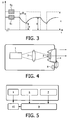
- the principle of operation of a still other embodiment is explained in the following with reference to Fig. 3 .
- the light output from the laser device 1 as measured by laser-output sensor 7 is modulated in time, which is shown by the dotted line (signal S 2 in Fig. 3 ).
- the signal measured by the phosphor-output detector looks like the solid line (signal S 1) in Fig. 3 since a phosphor has a finite response time, given by a decay time.
- the detected phosphor output is proportional to the phosphor-converted yellow light generated and might contain a fraction of the blue laser light.
- the laser output can be modulated in a periodic fashion. Due to the finite response time of the phosphor, the signal measured by the converted-light sensor 6 is delayed in phase relative to the signal measured by the laser-output sensor 7. Monitoring the modulation depth of the detected signals as well as the phase delay between them provides sufficient information to ascertain whether the light source is safe to operate.
- FIG. 4 Still another embodiment according to the invention is shown in Fig. 4 .
- only one photodiode is provided which forms the converted-light sensor 6.
- the role of the other photodiode in the embodiments described above is taken over by monitoring the driving current of the laser device 1. This current is proportional to the laser output, apart from a threshold current.
- a general schematic block diagram of the laser-based light source is shown in Fig. 5 .
- Part of the light emitted by the laser device 1 and part of the light converted by the light-conversion device 2 is detected by a laser-output sensor 7 and a converted-light sensor 6, respectively, as has been described above.
- These signals are read by a controller 9, which controls a laser driver 10.
- the laser driver 10 sets the laser power and can switch the beam on and off, or can switch it to an eye-safe intermediate state.
Landscapes
- Physics & Mathematics (AREA)
- Engineering & Computer Science (AREA)
- Optics & Photonics (AREA)
- General Engineering & Computer Science (AREA)
- Condensed Matter Physics & Semiconductors (AREA)
- General Physics & Mathematics (AREA)
- Electromagnetism (AREA)
- Microelectronics & Electronic Packaging (AREA)
- Semiconductor Lasers (AREA)
- Lasers (AREA)
Claims (15)
- Laserbasierte Lichtquelle mit
einer Lasereinrichtung (1), die so eingerichtet ist, dass sie Laserlicht einer zuvor festgelegten Laserwellenlänge erzeugt und dieses Laserlicht als einen Laserstrahl emittiert;
einer Lichtumwandlungseinrichtung (2), um zumindest einen Teil des Laserlichts in umgewandeltes Licht umzuwandeln;
einem Laserausgangssensor (7), um ein Laserausgangssignal zu ermitteln, das mit der Leistung des von der Lasereinrichtung (1) emittierten Laserlichts in Beziehung gesetzt wird;
einem auf das umgewandelte Licht ansprechenden Sensor (6), um ein mit der Leistung des von der Lichtumwandlungseinrichtung (7) emittierten umgewandelten Lichts in Beziehung gesetztes Signal für das umgewandelte Licht zu ermitteln; sowie
einer Steuereinrichtung (9), die so konfiguriert ist, dass sie das Laserausgangssignal empfängt und das Signal für das umgewandelte Licht empfängt, einen für den Betrieb sicheren Parameter aufgrund des Laserausgangssignals und des Signals für das umgewandelte Licht ermittelt und den Betrieb der laserbasierten Lichtquelle auf der Grundlage eines Vergleichs zwischen dem für den Betrieb sicheren Parameter und mindestens einem vorher definierten Schwellenwert steuert. - Laserbasierte Lichtquelle nach Anspruch 1, wobei der Laserausgangssensor (7) durch eine Laserlicht-Photodiode gebildet wird, die so ausgebildet ist, dass sie zumindest einen Teil des Laserlichts empfängt.
- Laserbasierte Lichtquelle nach Anspruch 1, wobei der Laserausgangssensor (7) durch einen Lasertreiberstrommonitor gebildet wird, der so eingerichtet ist, dass er den Lasertreiberstrom überwacht.
- Laserbasierte Lichtquelle nach einem der Ansprüche 1 bis 3, wobei der auf das umgewandelte Licht ansprechende Sensor (6) so eingerichtet ist, dass er zumindest einen Teil des umgewandelten Lichts empfängt.
- Laserbasierte Lichtquelle nach einem der Ansprüche 1 bis 4, wobei mindestens eine optische Faser (8) vorgesehen ist, die so ausgebildet ist, dass sie das Laserlicht zu der Lichtumwandlungseinrichtung (2) leitet.
- Laserbasierte Lichtquelle nach Anspruch 5, wobei eine optische Faser (8) vorgesehen ist, die so ausgebildet ist, dass sie zumindest einen Teil des umgewandelten Lichts in eine Richtung von der Lichtumwandlungseinrichtung (2) zurück zu dem auf das umgewandelte Licht ansprechenden Sensor (6) leitet.
- Laserbasierte Lichtquelle nach Anspruch 6, wobei der auf das umgewandelte Licht ansprechende Sensor (6) am Ende der optischen Faser (6), d.h. von der Lichtumwandlungseinrichtung (2) entfernt, angeordnet ist.
- Laserbasierte Lichtquelle nach Anspruch 6, wobei der auf das umgewandelte Licht ansprechende Sensor (6) an einer Stelle entlang der optischen Faser (8) angeordnet ist und eine Auskopplungseinrichtung vorgesehen ist, um das umgewandelte Licht aus der optischen Faser (8) auszukoppeln und in den auf das umgewandelte Licht ansprechenden Sensor einzukoppeln.
- Laserbasierte Lichtquelle nach einem der Ansprüche 5 bis 8, wobei die optische Faser (8) mit einer elektrischen Verdrahtung versehen ist, um Schäden an der optischen Faser (8) zu detektieren.
- Verfahren zum Betreiben einer laserbasierten Lichtquelle, das die folgenden Schritte umfasst, wonach:ein Laserlicht einer vorgegebenen Laserwellenlänge erzeugt und dieses Laserlicht als ein Laserstrahl emittiert wird;zumindest ein Teil des Laserlichts in umgewandeltes Licht umgewandelt wird;ein Signal für das umgewandelte Licht, das mit der Leistung des emittierten Laserlichts in Beziehung gesetzt wird, ermittelt wird; undein für den Betrieb sicherer Parameter aufgrund des Laserausgangssignals und des Signals für das umgewandelte Licht ermittelt wird;der für den Betrieb sichere Parameter mit mindestens einem vorher definierten Schwellenwert verglichen wird; undder Betrieb der laserbasierten Lichtquelle auf der Grundlage des Vergleichs des für den Betrieb sicheren Parameters mit dem vorher definierten Schwellenwert gesteuert wird.
- Verfahren nach Anspruch 10, das den Schritt des Vergleichens des für den Betrieb sicheren Parameters mit einem zweiten, vorher definierten Schwellenwert umfasst.
- Verfahren nach Anspruch 10 oder 11, das den Schritt des Ermittelns des für den Betrieb sicheren Parameters aufgrund eines Verhältnisses zwischen dem Laserausgangssignal und dem Signal für das umgewandelte Licht umfasst.
- Verfahren nach Anspruch 10 oder 11, das den Schritt des Ermittelns des für den Betrieb sicheren Parameters aufgrund der zeitlichen Ableitung des Verhältnisses zwischen dem Laserausgangssignal und dem Signal für das umgewandelte Licht umfasst.
- Verfahren nach Anspruch 10 oder 1l, das den Schritt des zeitlichen Modulierens des emittierten Laserstrahls sowie des
Ermittelns des für den Betrieb sicheren Parameters zu verschiedenen Zeitpunkten aufgrund eines Verhältnisses zwischen dem Laserausgangssignal und dem Signal für das umgewandelte Licht umfasst. - Verfahren nach Anspruch 10 oder 11, wobei der Schritt des Steuerns des Betriebs der laserbasierten Lichtquelle auf der Grundlage des Vergleichs des für den Betrieb sicheren Parameters mit dem vorher definierten Schwellenwert das Abschalten der Laseremission oder das Umschalten derselben auf ein sicheres Zwischenniveau und/oder Erzeugen eines Warnsignals umfasst.
Priority Applications (1)
| Application Number | Priority Date | Filing Date | Title |
|---|---|---|---|
| EP09786488A EP2297827B1 (de) | 2008-07-07 | 2009-06-30 | Augensichere beleuchtung auf laserbasis |
Applications Claiming Priority (3)
| Application Number | Priority Date | Filing Date | Title |
|---|---|---|---|
| EP08104656 | 2008-07-07 | ||
| EP09786488A EP2297827B1 (de) | 2008-07-07 | 2009-06-30 | Augensichere beleuchtung auf laserbasis |
| PCT/IB2009/052837 WO2010004477A2 (en) | 2008-07-07 | 2009-06-30 | Eye-safe laser-based lighting |
Publications (2)
| Publication Number | Publication Date |
|---|---|
| EP2297827A2 EP2297827A2 (de) | 2011-03-23 |
| EP2297827B1 true EP2297827B1 (de) | 2012-06-13 |
Family
ID=41278402
Family Applications (1)
| Application Number | Title | Priority Date | Filing Date |
|---|---|---|---|
| EP09786488A Active EP2297827B1 (de) | 2008-07-07 | 2009-06-30 | Augensichere beleuchtung auf laserbasis |
Country Status (6)
| Country | Link |
|---|---|
| US (3) | US20110116520A1 (de) |
| EP (1) | EP2297827B1 (de) |
| JP (1) | JP5677293B2 (de) |
| CN (1) | CN102089945B (de) |
| TW (1) | TW201010218A (de) |
| WO (1) | WO2010004477A2 (de) |
Cited By (4)
| Publication number | Priority date | Publication date | Assignee | Title |
|---|---|---|---|---|
| DE102015007748A1 (de) * | 2015-06-17 | 2016-12-22 | Osram Gmbh | Beleuchtungsvorrichtung mit Beleuchtungseinheit |
| DE102016207759A1 (de) | 2016-05-04 | 2017-11-09 | Osram Gmbh | Detektieren einer Beschädigung einer Konvertereinrichtung |
| EP3219547A4 (de) * | 2014-11-10 | 2017-11-15 | Panasonic Intellectual Property Management Co., Ltd. | Beleuchtungsvorrichtung und damit ausgestattetes kraftfahrzeug |
| WO2022117422A1 (en) | 2020-12-01 | 2022-06-09 | Signify Holding B.V. | A laser-based lighting device |
Families Citing this family (60)
| Publication number | Priority date | Publication date | Assignee | Title |
|---|---|---|---|---|
| JP5488908B2 (ja) * | 2010-06-14 | 2014-05-14 | カシオ計算機株式会社 | プロジェクタ |
| EP2461090B1 (de) * | 2010-12-01 | 2020-07-01 | Stanley Electric Co., Ltd. | Fahrzeuglicht |
| JP5657357B2 (ja) * | 2010-12-01 | 2015-01-21 | スタンレー電気株式会社 | 車両用灯具 |
| US20130041357A1 (en) * | 2011-08-12 | 2013-02-14 | Ceramoptec Industries Inc. | Class 1 laser treatment system |
| CN102801470B (zh) * | 2012-01-14 | 2016-03-16 | 深圳市光峰光电技术有限公司 | 信号光发射装置和光通信系统 |
| DE102012215702A1 (de) * | 2012-09-05 | 2014-03-06 | Osram Gmbh | Beleuchtungseinrichtung |
| FR3007820B1 (fr) * | 2013-06-28 | 2017-09-08 | Valeo Vision | Module optique securise pour vehicule automobile comprenant une source laser |
| JP5997676B2 (ja) * | 2013-10-03 | 2016-09-28 | 富士フイルム株式会社 | 内視鏡用光源装置、およびこれを用いた内視鏡システム |
| JP2015146396A (ja) * | 2014-02-03 | 2015-08-13 | スタンレー電気株式会社 | 発光装置、車両用灯具、及び、車両用照明装置 |
| DE102014202294A1 (de) * | 2014-02-07 | 2015-08-13 | Osram Gmbh | Beleuchtungseinrichtung und Verfahren zum Betreiben einer Beleuchtungseinrichtung |
| DE102014202943A1 (de) * | 2014-02-18 | 2015-08-20 | Osram Gmbh | Beleuchtungsvorrichtung mit Primärlichtquelle und Leuchtstoffvolumen |
| EP3114737B1 (de) * | 2014-03-04 | 2024-04-17 | IPG Photonics Corporation | Sicherheitssteuerungssystem für hochleistungsfaserlaser |
| DE102014205294A1 (de) * | 2014-03-21 | 2015-09-24 | Automotive Lighting Reutlingen Gmbh | Beleuchtungseinrichtung |
| DE102014207024A1 (de) * | 2014-04-11 | 2015-10-15 | Osram Gmbh | Leuchtvorrichtung mit Lichtquelle und beabstandetem Leuchtstoffkörper |
| DE102014214601A1 (de) * | 2014-07-24 | 2016-01-28 | Osram Gmbh | Beleuchtungsvorrichtung mit mindestens einem Lichtsensor |
| US9551569B2 (en) * | 2014-10-13 | 2017-01-24 | Hermes-Epitek Corporation | Apparatus and method for curvature and thin film stress measurement |
| JP6688226B2 (ja) | 2014-12-03 | 2020-04-28 | 株式会社小糸製作所 | 車両用灯具およびその光源の異常検出器 |
| DE102014226661A1 (de) * | 2014-12-19 | 2016-06-23 | Osram Gmbh | Leuchtvorrichtung |
| FR3034170B1 (fr) * | 2015-03-24 | 2018-09-07 | Valeo Vision | Module d'eclairage laser a dispositif de securite |
| DE102015104499A1 (de) * | 2015-03-25 | 2016-09-29 | Hella Kgaa Hueck & Co. | Beleuchtungsvorrichtung für Fahrzeuge |
| DE102015104506A1 (de) * | 2015-03-25 | 2016-09-29 | Hella Kgaa Hueck & Co. | Beleuchtungsvorrichtung für Fahrzeuge |
| DE102015208576A1 (de) * | 2015-05-08 | 2016-11-10 | Osram Gmbh | Beleuchtungsvorrichtung mit Pumpstrahlungsquelle |
| FR3036775B1 (fr) * | 2015-05-29 | 2017-06-16 | Valeo Vision | Module d'eclairage securise avec source lumineuse laser |
| DE102015108876B3 (de) * | 2015-06-04 | 2016-03-03 | Otto-Von-Guericke-Universität Magdeburg, Ttz Patentwesen | Lichtemittierendes Gruppe-III-Nitrid basiertes Bauelement |
| EP3104474A1 (de) * | 2015-06-08 | 2016-12-14 | Jabil Circuit Belgium NV | Verbesserte, augensichere, laserbasierte beleuchtung |
| JP6379356B2 (ja) * | 2015-09-28 | 2018-08-29 | パナソニックIpマネジメント株式会社 | 照明装置と、それを搭載した自動車 |
| AT518010B1 (de) * | 2015-10-23 | 2017-10-15 | Zkw Group Gmbh | Überwachunsvorrichtung zur Überwachung des Betriebszustandes eines Laser-Fahzeugscheinwerfers sowie Fahrzeugscheinwerfer |
| FR3044389A1 (fr) * | 2015-11-26 | 2017-06-02 | Valeo Vision | Dispositif de gestion de la couleur d'un eclairage pour vehicule automobile |
| DE102016101192A1 (de) * | 2016-01-25 | 2017-07-27 | Hella Kgaa Hueck & Co. | Beleuchtungsvorrichtung für Fahrzeuge |
| CN205535108U (zh) * | 2016-01-28 | 2016-08-31 | 深圳市雷得科技有限公司 | 多功能保护激光灯 |
| DE102016104946A1 (de) * | 2016-03-17 | 2017-09-21 | Osram Opto Semiconductors Gmbh | Optoelektronisches Bauelement und Verfahren zum Betreiben eines optoelektronischen Bauelements |
| DE102016207757B4 (de) * | 2016-05-04 | 2023-06-01 | Osram Gmbh | Leuchtvorrichtung |
| JP6678517B2 (ja) * | 2016-05-31 | 2020-04-08 | シャープ株式会社 | 照明装置 |
| FR3054094A1 (fr) * | 2016-06-09 | 2018-01-19 | Valeo Vision | Securisation d'un module lumineux comprenant une source laser |
| DE102016214517A1 (de) | 2016-08-05 | 2018-02-08 | Osram Gmbh | Beleuchtungsvorrichtung |
| DE102016117840A1 (de) * | 2016-09-21 | 2018-03-22 | Automotive Lighting Reutlingen Gmbh | Beleuchtungseinrichtung für ein Kraftfahrzeug |
| CN108303838A (zh) * | 2016-09-27 | 2018-07-20 | 中航国画(上海)激光显示科技有限公司 | 一种蓝光光源全光纤传输激光投影机 |
| DE102016220928B4 (de) * | 2016-10-25 | 2023-02-23 | Osram Gmbh | Beleuchtungsvorrichtung |
| JP6909801B2 (ja) | 2016-11-04 | 2021-07-28 | ヌヴォトンテクノロジージャパン株式会社 | 光源装置 |
| JP6690610B2 (ja) | 2017-07-28 | 2020-04-28 | 日亜化学工業株式会社 | 発光装置 |
| JP7277841B2 (ja) * | 2017-12-25 | 2023-05-19 | 日亜化学工業株式会社 | 発光装置 |
| CN107861248B (zh) * | 2017-12-25 | 2023-12-26 | 歌尔光学科技有限公司 | 激光束扫描显示设备及增强现实眼镜 |
| US10386052B2 (en) * | 2018-01-08 | 2019-08-20 | Tridonic Gmbh & Co Kg | Method of identifying a malfunction in a laser-driven remote phosphor luminaire |
| DE112020001532B4 (de) | 2019-03-27 | 2025-07-24 | Ams Sensors Singapore Pte. Ltd. | Sicherheitsverriegelungssystem für beleuchtungssysteme |
| JP7266195B2 (ja) * | 2019-08-29 | 2023-04-28 | パナソニックIpマネジメント株式会社 | 照明システム及び照明システムの制御方法 |
| JP7266194B2 (ja) * | 2019-08-29 | 2023-04-28 | パナソニックIpマネジメント株式会社 | 照明システム及び照明システムの制御方法 |
| DE102020206180A1 (de) * | 2020-05-15 | 2021-11-18 | Fraunhofer-Gesellschaft zur Förderung der angewandten Forschung e.V. | Augensichere optisch-drahtlose kommunikation |
| JP7597996B2 (ja) | 2020-05-26 | 2024-12-11 | 日亜化学工業株式会社 | 発光装置 |
| JP2022055932A (ja) | 2020-09-29 | 2022-04-08 | パナソニックIpマネジメント株式会社 | 光源装置 |
| US12224387B2 (en) | 2020-12-24 | 2025-02-11 | Nichia Corporation | Light emitting device |
| JP7580047B2 (ja) | 2021-03-26 | 2024-11-11 | パナソニックIpマネジメント株式会社 | 光源装置 |
| US12345595B2 (en) * | 2021-10-27 | 2025-07-01 | Ii-Vi Delaware, Inc. | Eye safety interlock for fiber-coupled high power laser sources |
| EP4198480B1 (de) * | 2021-12-16 | 2025-02-26 | AIRBUS HELICOPTERS DEUTSCHLAND GmbH | Optisches integritätsüberwachungsgerät für ein optisches system |
| CN115413091B (zh) * | 2021-12-21 | 2025-02-28 | 广州光联电子科技有限公司 | 激光调节方法、装置和系统 |
| CN114500795B (zh) * | 2021-12-27 | 2024-03-15 | 奥比中光科技集团股份有限公司 | 激光安全控制方法、装置、智能门锁及存储介质 |
| US11784715B2 (en) * | 2022-02-01 | 2023-10-10 | Prime World International Holdings Ltd. | Optical communication system capable of ensuring operation safety of external laser source |
| WO2023228913A1 (ja) * | 2022-05-24 | 2023-11-30 | ニデックプレシジョン株式会社 | 照明装置 |
| WO2023228914A1 (ja) * | 2022-05-27 | 2023-11-30 | ニデックプレシジョン株式会社 | 照明装置及び照明方法 |
| CN119732175A (zh) * | 2022-08-24 | 2025-03-28 | 尼得科精密部件株式会社 | 照明装置和照明方法 |
| US12166326B1 (en) | 2023-11-30 | 2024-12-10 | InnoVoyce LLC | Fiber laser with optical feedback for contaminant detection and other functionality |
Family Cites Families (58)
| Publication number | Priority date | Publication date | Assignee | Title |
|---|---|---|---|---|
| JPS54103098U (de) * | 1977-12-29 | 1979-07-20 | ||
| US4680810A (en) * | 1985-06-28 | 1987-07-14 | American Telephone And Telegraph Company, At&T Bell Labs | Means for controlling a semiconductor device and communication system comprising the means |
| US4994059A (en) * | 1986-05-09 | 1991-02-19 | Gv Medical, Inc. | Laser catheter feedback system |
| EP0378061B1 (de) * | 1989-01-13 | 1996-02-28 | International Business Machines Corporation | Verfahren und Vorrichtung zur Erzeugung von blaugrüner Lichtstrahlung |
| US5694546A (en) * | 1994-05-31 | 1997-12-02 | Reisman; Richard R. | System for automatic unattended electronic information transport between a server and a client by a vendor provided transport software with a manifest list |
| US5552926A (en) * | 1994-10-07 | 1996-09-03 | International Business Machines Corporation | Device and method for wavelength conversion and BBO crystal for wavelength conversion |
| JPH0964445A (ja) * | 1995-08-24 | 1997-03-07 | Tokai Rika Co Ltd | レーザ光出射装置の安全装置 |
| US5835650A (en) * | 1995-11-16 | 1998-11-10 | Matsushita Electric Industrial Co., Ltd. | Optical apparatus and method for producing the same |
| US6340824B1 (en) * | 1997-09-01 | 2002-01-22 | Kabushiki Kaisha Toshiba | Semiconductor light emitting device including a fluorescent material |
| AU1262499A (en) * | 1998-03-11 | 1999-09-27 | Nikon Corporation | Ultraviolet laser apparatus and exposure apparatus comprising the ultraviolet laser apparatus |
| US6535327B1 (en) * | 2000-02-02 | 2003-03-18 | Picarro, Inc. | CGA optical parametric oscillator |
| TW463433B (en) * | 2000-03-07 | 2001-11-11 | Ind Tech Res Inst | Laser light output transmission reflecting device |
| JP2002045329A (ja) * | 2000-08-01 | 2002-02-12 | Fuji Photo Film Co Ltd | 蛍光画像表示装置 |
| US6747406B1 (en) * | 2000-08-07 | 2004-06-08 | General Electric Company | LED cross-linkable phospor coating |
| US6845113B2 (en) * | 2000-10-31 | 2005-01-18 | Matsushita Electric Industrial Co., Ltd. | Coherent light source and recording/reproducing apparatus using the same |
| JP2002329924A (ja) * | 2001-03-02 | 2002-11-15 | Ricoh Co Ltd | Ld制御装置及びldの劣化検知方法 |
| JP4290900B2 (ja) * | 2001-05-18 | 2009-07-08 | 日本ビクター株式会社 | 光源装置 |
| US7010006B2 (en) * | 2001-06-22 | 2006-03-07 | Matsushita Electric Industrial Co., Ltd. | Light source apparatus and its control method |
| US20030002109A1 (en) * | 2001-06-29 | 2003-01-02 | Jim Hochberg | Eye safety shutdown |
| JP2003072141A (ja) * | 2001-09-04 | 2003-03-12 | Konica Corp | 網点画像露光装置及び光源駆動回路 |
| US6693268B2 (en) * | 2001-09-24 | 2004-02-17 | Coretek Opto Corporation | Auto feedback and photo attenuation structure of vertical cavity surface emitting laser |
| DK1455671T3 (da) * | 2001-12-10 | 2007-10-01 | Inolase 2002 Ltd | Fremgangsmåde og apparat til forbedring af sikkerhed under eksponering for en monokromatisk lyskilde |
| JP2003279444A (ja) * | 2002-03-26 | 2003-10-02 | Mitsubishi Cable Ind Ltd | 光ファイバ損傷検知装置及びこれを備えたレーザ伝送装置 |
| JP4201167B2 (ja) * | 2002-09-26 | 2008-12-24 | シチズン電子株式会社 | 白色発光装置の製造方法 |
| JP2004184852A (ja) * | 2002-12-05 | 2004-07-02 | Olympus Corp | 表示装置、光源装置、及び照明装置 |
| JP2004281588A (ja) * | 2003-03-14 | 2004-10-07 | Ricoh Co Ltd | レーザダイオード制御装置及び画像形成装置 |
| JP4417784B2 (ja) * | 2003-09-05 | 2010-02-17 | シャープ株式会社 | 発光装置及び表示装置 |
| US6984039B2 (en) * | 2003-12-01 | 2006-01-10 | Eastman Kodak Company | Laser projector having silhouette blanking for objects in the output light path |
| JP2005208333A (ja) * | 2004-01-22 | 2005-08-04 | Sharp Corp | フラッシュ装置、フラッシュ装置を備えるカメラ、および半導体レーザ装置とその製造方法 |
| JP4459724B2 (ja) * | 2004-06-08 | 2010-04-28 | Hoya株式会社 | 内視鏡用光源装置 |
| WO2006073492A2 (en) * | 2004-07-30 | 2006-07-13 | Biovigilant Systems, Inc. | Pathogen and particle detector system and method |
| US7286581B2 (en) * | 2004-08-20 | 2007-10-23 | Avago Technologies Fiber Ip (Singapore) Pte Ltd | Self-monitoring light emitting apparatus |
| US7346087B2 (en) * | 2005-03-04 | 2008-03-18 | Finisar Corporation | Method for performing eye safety measurements on laser emitter devices |
| EP1900258A1 (de) * | 2005-06-29 | 2008-03-19 | Koninklijke Philips Electronics N.V. | Steuerungssystem zur steuerung der lichtleistung einer led-einheit |
| JP4812430B2 (ja) * | 2005-12-28 | 2011-11-09 | オリンパス株式会社 | 内視鏡装置 |
| KR101184957B1 (ko) * | 2006-02-10 | 2012-10-02 | 미쓰비시 가가꾸 가부시키가이샤 | 형광체 및 그 제조 방법, 형광체 함유 조성물, 발광 장치, 그리고 화상 표시 장치 및 조명 장치 |
| JP4880329B2 (ja) * | 2006-03-06 | 2012-02-22 | 株式会社小糸製作所 | 車両用灯具 |
| US7695164B2 (en) * | 2006-05-24 | 2010-04-13 | Osram Gesellschaft Mit Beschraenkter Haftung | Illumination system for imaging illumination with a high level of homogeneity |
| US7529281B2 (en) * | 2006-07-11 | 2009-05-05 | Mobius Photonics, Inc. | Light source with precisely controlled wavelength-converted average power |
| US7959341B2 (en) * | 2006-07-20 | 2011-06-14 | Rambus International Ltd. | LED color management and display systems |
| US7796324B2 (en) * | 2006-10-10 | 2010-09-14 | Panasonic Corporation | Wavelength converting apparatus and image displaying apparatus |
| KR20090082449A (ko) * | 2006-10-31 | 2009-07-30 | 티아이알 테크놀로지 엘피 | 광원 |
| JP5103874B2 (ja) * | 2006-11-15 | 2012-12-19 | 日亜化学工業株式会社 | 発光装置 |
| US7826502B2 (en) * | 2006-12-14 | 2010-11-02 | Jds Uniphase Corporation | Circuit and method for lessening noise in a laser system having a frequency converting element |
| US7902560B2 (en) * | 2006-12-15 | 2011-03-08 | Koninklijke Philips Electronics N.V. | Tunable white point light source using a wavelength converting element |
| JP4975797B2 (ja) * | 2009-10-14 | 2012-07-11 | シャープ株式会社 | 照明装置、車両用灯具および車両 |
| DE102012201790A1 (de) * | 2012-02-07 | 2013-08-08 | Osram Gmbh | Beleuchtungsvorrichtung mit einer pumplasermatrix und verfahren zum betreiben dieser beleuchtungsvorrichtung |
| DE102014202943A1 (de) * | 2014-02-18 | 2015-08-20 | Osram Gmbh | Beleuchtungsvorrichtung mit Primärlichtquelle und Leuchtstoffvolumen |
| DE102014207024A1 (de) * | 2014-04-11 | 2015-10-15 | Osram Gmbh | Leuchtvorrichtung mit Lichtquelle und beabstandetem Leuchtstoffkörper |
| DE102014215221A1 (de) * | 2014-08-01 | 2016-02-04 | Osram Gmbh | Beleuchtungsvorrichtung mit von einer Lichtquelle beabstandetem Leuchtstoffkörper |
| US9787963B2 (en) * | 2015-10-08 | 2017-10-10 | Soraa Laser Diode, Inc. | Laser lighting having selective resolution |
| DE102016207759A1 (de) * | 2016-05-04 | 2017-11-09 | Osram Gmbh | Detektieren einer Beschädigung einer Konvertereinrichtung |
| DE102016207757B4 (de) * | 2016-05-04 | 2023-06-01 | Osram Gmbh | Leuchtvorrichtung |
| DE102016214517A1 (de) * | 2016-08-05 | 2018-02-08 | Osram Gmbh | Beleuchtungsvorrichtung |
| DE102017101091A1 (de) * | 2017-01-20 | 2018-07-26 | Osram Gmbh | Konverter, laser activated remote phosphor (larp) system, scheinwerfer und verfahren |
| DE102017212411A1 (de) * | 2017-07-19 | 2019-01-24 | Osram Gmbh | Lichtmodul, scheinwerfer und verfahren zur bereitstellung von polychromatischem licht |
| DE102018201425A1 (de) * | 2018-01-30 | 2019-08-01 | Osram Gmbh | Konversionsbaugruppe mit anschlussrahmen |
| DE112020001131T5 (de) * | 2019-03-08 | 2022-01-27 | Osram Gmbh | Komponente für ein Lidar-Sensorsystem, Lidar-Sensorsystem, Lidar-Sensorgerät, Verfahren für ein Lidar-Sensorsystem und Verfahren für ein Lidar-Sensorgerät |
-
2008
- 2008-07-07 US US13/001,858 patent/US20110116520A1/en not_active Abandoned
-
2009
- 2009-06-30 WO PCT/IB2009/052837 patent/WO2010004477A2/en not_active Ceased
- 2009-06-30 EP EP09786488A patent/EP2297827B1/de active Active
- 2009-06-30 CN CN2009801264428A patent/CN102089945B/zh active Active
- 2009-06-30 JP JP2011517280A patent/JP5677293B2/ja active Active
- 2009-07-06 TW TW098122815A patent/TW201010218A/zh unknown
-
2015
- 2015-09-08 US US14/848,306 patent/US11549651B2/en active Active
-
2019
- 2019-01-31 US US16/263,698 patent/US20190165543A1/en active Pending
Cited By (6)
| Publication number | Priority date | Publication date | Assignee | Title |
|---|---|---|---|---|
| EP3219547A4 (de) * | 2014-11-10 | 2017-11-15 | Panasonic Intellectual Property Management Co., Ltd. | Beleuchtungsvorrichtung und damit ausgestattetes kraftfahrzeug |
| US10174897B2 (en) | 2014-11-10 | 2019-01-08 | Panasonic Intellectual Property Management Co., Ltd. | Illumination device and automobile equipped with same |
| DE102015007748A1 (de) * | 2015-06-17 | 2016-12-22 | Osram Gmbh | Beleuchtungsvorrichtung mit Beleuchtungseinheit |
| DE102016207759A1 (de) | 2016-05-04 | 2017-11-09 | Osram Gmbh | Detektieren einer Beschädigung einer Konvertereinrichtung |
| US10436714B2 (en) | 2016-05-04 | 2019-10-08 | Osram Gmbh | Detecting damage to a converter device |
| WO2022117422A1 (en) | 2020-12-01 | 2022-06-09 | Signify Holding B.V. | A laser-based lighting device |
Also Published As
| Publication number | Publication date |
|---|---|
| JP2011527518A (ja) | 2011-10-27 |
| US20110116520A1 (en) | 2011-05-19 |
| CN102089945B (zh) | 2013-03-27 |
| JP5677293B2 (ja) | 2015-02-25 |
| CN102089945A (zh) | 2011-06-08 |
| US20150380899A1 (en) | 2015-12-31 |
| TW201010218A (en) | 2010-03-01 |
| EP2297827A2 (de) | 2011-03-23 |
| US11549651B2 (en) | 2023-01-10 |
| WO2010004477A3 (en) | 2010-02-25 |
| US20190165543A1 (en) | 2019-05-30 |
| WO2010004477A2 (en) | 2010-01-14 |
Similar Documents
| Publication | Publication Date | Title |
|---|---|---|
| EP2297827B1 (de) | Augensichere beleuchtung auf laserbasis | |
| US8502695B2 (en) | Light emitting device, illumination device, and photo sensor | |
| US20080187319A1 (en) | Multi-channel optoelectronic module | |
| US20090003843A1 (en) | Optical transmitter and method for control the same | |
| CN110832646A (zh) | 紫外线发光装置 | |
| JP2006013252A (ja) | レーザダイオードの制御方法、制御回路、および光送信器 | |
| KR20220141850A (ko) | 다중 채널 프로그래밍 가능 검출 센서 | |
| CN114284841A (zh) | 一种光纤激光器及其控制方法 | |
| JP2017213980A (ja) | 照明装置、及び、レーザ素子の駆動方法 | |
| CN109831255B (zh) | 飞行时间组件的控制系统和终端 | |
| TW200939628A (en) | Photoelectric sensor | |
| US6678290B2 (en) | Optical output control circuit for obtaining stable optical output power | |
| CN118705569A (zh) | 一种量测改进行激光灯 | |
| EP3512054B1 (de) | Verfahren zur erkennung einer fehlfunktion in einer laserbetriebenen entfernten phosphorleuchte | |
| JP2015210890A (ja) | 光源装置および車両 | |
| JP7266241B2 (ja) | 光検出装置、照明点灯装置、及び照明システム | |
| CA2504691A1 (en) | Age compensation in optoelectronic modules with integrated temperature control | |
| US7505691B2 (en) | Optical emission module | |
| JP2006238185A (ja) | 光電スイッチ用投光ヘッド | |
| US9325153B2 (en) | Method to control transmitter optical module | |
| EP2955801B1 (de) | Verfahren zur beurteilung der optischen leistungsabnahme eines ausgangs bei einer optischen verstärkungsvorrichtung und optisches verstärkungssystem | |
| US6441940B1 (en) | Wavelength stabilization of light emitting components | |
| JP3023739B2 (ja) | 光送信装置 | |
| WO2025263225A1 (ja) | 投光器、測定装置、投光器の制御方法、コンピュータプログラム、および、コンピュータプログラムを記録したコンピュータ読み取り可能な記録媒体 | |
| JPH10229231A (ja) | 光送信装置 |
Legal Events
| Date | Code | Title | Description |
|---|---|---|---|
| PUAI | Public reference made under article 153(3) epc to a published international application that has entered the european phase |
Free format text: ORIGINAL CODE: 0009012 |
|
| 17P | Request for examination filed |
Effective date: 20110207 |
|
| AK | Designated contracting states |
Kind code of ref document: A2 Designated state(s): AT BE BG CH CY CZ DE DK EE ES FI FR GB GR HR HU IE IS IT LI LT LU LV MC MK MT NL NO PL PT RO SE SI SK TR |
|
| AX | Request for extension of the european patent |
Extension state: AL BA RS |
|
| DAX | Request for extension of the european patent (deleted) | ||
| GRAP | Despatch of communication of intention to grant a patent |
Free format text: ORIGINAL CODE: EPIDOSNIGR1 |
|
| GRAS | Grant fee paid |
Free format text: ORIGINAL CODE: EPIDOSNIGR3 |
|
| GRAA | (expected) grant |
Free format text: ORIGINAL CODE: 0009210 |
|
| AK | Designated contracting states |
Kind code of ref document: B1 Designated state(s): AT BE BG CH CY CZ DE DK EE ES FI FR GB GR HR HU IE IS IT LI LT LU LV MC MK MT NL NO PL PT RO SE SI SK TR |
|
| REG | Reference to a national code |
Ref country code: GB Ref legal event code: FG4D |
|
| REG | Reference to a national code |
Ref country code: AT Ref legal event code: REF Ref document number: 562359 Country of ref document: AT Kind code of ref document: T Effective date: 20120615 Ref country code: CH Ref legal event code: EP |
|
| REG | Reference to a national code |
Ref country code: IE Ref legal event code: FG4D |
|
| REG | Reference to a national code |
Ref country code: DE Ref legal event code: R096 Ref document number: 602009007577 Country of ref document: DE Effective date: 20120809 |
|
| REG | Reference to a national code |
Ref country code: NL Ref legal event code: VDEP Effective date: 20120613 |
|
| PG25 | Lapsed in a contracting state [announced via postgrant information from national office to epo] |
Ref country code: SE Free format text: LAPSE BECAUSE OF FAILURE TO SUBMIT A TRANSLATION OF THE DESCRIPTION OR TO PAY THE FEE WITHIN THE PRESCRIBED TIME-LIMIT Effective date: 20120613 Ref country code: LT Free format text: LAPSE BECAUSE OF FAILURE TO SUBMIT A TRANSLATION OF THE DESCRIPTION OR TO PAY THE FEE WITHIN THE PRESCRIBED TIME-LIMIT Effective date: 20120613 Ref country code: NO Free format text: LAPSE BECAUSE OF FAILURE TO SUBMIT A TRANSLATION OF THE DESCRIPTION OR TO PAY THE FEE WITHIN THE PRESCRIBED TIME-LIMIT Effective date: 20120913 Ref country code: CY Free format text: LAPSE BECAUSE OF FAILURE TO SUBMIT A TRANSLATION OF THE DESCRIPTION OR TO PAY THE FEE WITHIN THE PRESCRIBED TIME-LIMIT Effective date: 20120613 Ref country code: FI Free format text: LAPSE BECAUSE OF FAILURE TO SUBMIT A TRANSLATION OF THE DESCRIPTION OR TO PAY THE FEE WITHIN THE PRESCRIBED TIME-LIMIT Effective date: 20120613 |
|
| REG | Reference to a national code |
Ref country code: AT Ref legal event code: MK05 Ref document number: 562359 Country of ref document: AT Kind code of ref document: T Effective date: 20120613 |
|
| REG | Reference to a national code |
Ref country code: LT Ref legal event code: MG4D Effective date: 20120613 |
|
| PG25 | Lapsed in a contracting state [announced via postgrant information from national office to epo] |
Ref country code: HR Free format text: LAPSE BECAUSE OF FAILURE TO SUBMIT A TRANSLATION OF THE DESCRIPTION OR TO PAY THE FEE WITHIN THE PRESCRIBED TIME-LIMIT Effective date: 20120613 Ref country code: LV Free format text: LAPSE BECAUSE OF FAILURE TO SUBMIT A TRANSLATION OF THE DESCRIPTION OR TO PAY THE FEE WITHIN THE PRESCRIBED TIME-LIMIT Effective date: 20120613 Ref country code: SI Free format text: LAPSE BECAUSE OF FAILURE TO SUBMIT A TRANSLATION OF THE DESCRIPTION OR TO PAY THE FEE WITHIN THE PRESCRIBED TIME-LIMIT Effective date: 20120613 Ref country code: GR Free format text: LAPSE BECAUSE OF FAILURE TO SUBMIT A TRANSLATION OF THE DESCRIPTION OR TO PAY THE FEE WITHIN THE PRESCRIBED TIME-LIMIT Effective date: 20120914 |
|
| PG25 | Lapsed in a contracting state [announced via postgrant information from national office to epo] |
Ref country code: AT Free format text: LAPSE BECAUSE OF FAILURE TO SUBMIT A TRANSLATION OF THE DESCRIPTION OR TO PAY THE FEE WITHIN THE PRESCRIBED TIME-LIMIT Effective date: 20120613 Ref country code: IS Free format text: LAPSE BECAUSE OF FAILURE TO SUBMIT A TRANSLATION OF THE DESCRIPTION OR TO PAY THE FEE WITHIN THE PRESCRIBED TIME-LIMIT Effective date: 20121013 Ref country code: MC Free format text: LAPSE BECAUSE OF NON-PAYMENT OF DUE FEES Effective date: 20120630 Ref country code: EE Free format text: LAPSE BECAUSE OF FAILURE TO SUBMIT A TRANSLATION OF THE DESCRIPTION OR TO PAY THE FEE WITHIN THE PRESCRIBED TIME-LIMIT Effective date: 20120613 Ref country code: RO Free format text: LAPSE BECAUSE OF FAILURE TO SUBMIT A TRANSLATION OF THE DESCRIPTION OR TO PAY THE FEE WITHIN THE PRESCRIBED TIME-LIMIT Effective date: 20120613 Ref country code: CZ Free format text: LAPSE BECAUSE OF FAILURE TO SUBMIT A TRANSLATION OF THE DESCRIPTION OR TO PAY THE FEE WITHIN THE PRESCRIBED TIME-LIMIT Effective date: 20120613 Ref country code: BE Free format text: LAPSE BECAUSE OF FAILURE TO SUBMIT A TRANSLATION OF THE DESCRIPTION OR TO PAY THE FEE WITHIN THE PRESCRIBED TIME-LIMIT Effective date: 20120613 Ref country code: SK Free format text: LAPSE BECAUSE OF FAILURE TO SUBMIT A TRANSLATION OF THE DESCRIPTION OR TO PAY THE FEE WITHIN THE PRESCRIBED TIME-LIMIT Effective date: 20120613 |
|
| PG25 | Lapsed in a contracting state [announced via postgrant information from national office to epo] |
Ref country code: IT Free format text: LAPSE BECAUSE OF FAILURE TO SUBMIT A TRANSLATION OF THE DESCRIPTION OR TO PAY THE FEE WITHIN THE PRESCRIBED TIME-LIMIT Effective date: 20120613 Ref country code: MK Free format text: LAPSE BECAUSE OF FAILURE TO SUBMIT A TRANSLATION OF THE DESCRIPTION OR TO PAY THE FEE WITHIN THE PRESCRIBED TIME-LIMIT Effective date: 20120613 Ref country code: PL Free format text: LAPSE BECAUSE OF FAILURE TO SUBMIT A TRANSLATION OF THE DESCRIPTION OR TO PAY THE FEE WITHIN THE PRESCRIBED TIME-LIMIT Effective date: 20120613 Ref country code: PT Free format text: LAPSE BECAUSE OF FAILURE TO SUBMIT A TRANSLATION OF THE DESCRIPTION OR TO PAY THE FEE WITHIN THE PRESCRIBED TIME-LIMIT Effective date: 20121015 |
|
| REG | Reference to a national code |
Ref country code: IE Ref legal event code: MM4A |
|
| PG25 | Lapsed in a contracting state [announced via postgrant information from national office to epo] |
Ref country code: NL Free format text: LAPSE BECAUSE OF FAILURE TO SUBMIT A TRANSLATION OF THE DESCRIPTION OR TO PAY THE FEE WITHIN THE PRESCRIBED TIME-LIMIT Effective date: 20120613 |
|
| PLBE | No opposition filed within time limit |
Free format text: ORIGINAL CODE: 0009261 |
|
| STAA | Information on the status of an ep patent application or granted ep patent |
Free format text: STATUS: NO OPPOSITION FILED WITHIN TIME LIMIT |
|
| PG25 | Lapsed in a contracting state [announced via postgrant information from national office to epo] |
Ref country code: IE Free format text: LAPSE BECAUSE OF NON-PAYMENT OF DUE FEES Effective date: 20120630 Ref country code: DK Free format text: LAPSE BECAUSE OF FAILURE TO SUBMIT A TRANSLATION OF THE DESCRIPTION OR TO PAY THE FEE WITHIN THE PRESCRIBED TIME-LIMIT Effective date: 20120613 Ref country code: ES Free format text: LAPSE BECAUSE OF FAILURE TO SUBMIT A TRANSLATION OF THE DESCRIPTION OR TO PAY THE FEE WITHIN THE PRESCRIBED TIME-LIMIT Effective date: 20120924 |
|
| 26N | No opposition filed |
Effective date: 20130314 |
|
| REG | Reference to a national code |
Ref country code: DE Ref legal event code: R097 Ref document number: 602009007577 Country of ref document: DE Effective date: 20130314 |
|
| PG25 | Lapsed in a contracting state [announced via postgrant information from national office to epo] |
Ref country code: MT Free format text: LAPSE BECAUSE OF FAILURE TO SUBMIT A TRANSLATION OF THE DESCRIPTION OR TO PAY THE FEE WITHIN THE PRESCRIBED TIME-LIMIT Effective date: 20120613 Ref country code: BG Free format text: LAPSE BECAUSE OF FAILURE TO SUBMIT A TRANSLATION OF THE DESCRIPTION OR TO PAY THE FEE WITHIN THE PRESCRIBED TIME-LIMIT Effective date: 20120913 |
|
| REG | Reference to a national code |
Ref country code: CH Ref legal event code: PL |
|
| REG | Reference to a national code |
Ref country code: DE Ref legal event code: R082 Ref document number: 602009007577 Country of ref document: DE Representative=s name: MEISSNER, BOLTE & PARTNER GBR, DE |
|
| PG25 | Lapsed in a contracting state [announced via postgrant information from national office to epo] |
Ref country code: CH Free format text: LAPSE BECAUSE OF NON-PAYMENT OF DUE FEES Effective date: 20130630 Ref country code: TR Free format text: LAPSE BECAUSE OF FAILURE TO SUBMIT A TRANSLATION OF THE DESCRIPTION OR TO PAY THE FEE WITHIN THE PRESCRIBED TIME-LIMIT Effective date: 20120613 Ref country code: LI Free format text: LAPSE BECAUSE OF NON-PAYMENT OF DUE FEES Effective date: 20130630 |
|
| REG | Reference to a national code |
Ref country code: DE Ref legal event code: R082 Ref document number: 602009007577 Country of ref document: DE Representative=s name: MEISSNER BOLTE PATENTANWAELTE RECHTSANWAELTE P, DE Effective date: 20140328 Ref country code: DE Ref legal event code: R081 Ref document number: 602009007577 Country of ref document: DE Owner name: PHILIPS LIGHTING HOLDING B.V., NL Free format text: FORMER OWNER: KONINKLIJKE PHILIPS ELECTRONICS N.V., EINDHOVEN, NL Effective date: 20140328 Ref country code: DE Ref legal event code: R082 Ref document number: 602009007577 Country of ref document: DE Representative=s name: MEISSNER, BOLTE & PARTNER GBR, DE Effective date: 20140328 Ref country code: DE Ref legal event code: R081 Ref document number: 602009007577 Country of ref document: DE Owner name: KONINKLIJKE PHILIPS N.V., NL Free format text: FORMER OWNER: KONINKLIJKE PHILIPS ELECTRONICS N.V., EINDHOVEN, NL Effective date: 20140328 |
|
| PG25 | Lapsed in a contracting state [announced via postgrant information from national office to epo] |
Ref country code: LU Free format text: LAPSE BECAUSE OF NON-PAYMENT OF DUE FEES Effective date: 20120630 |
|
| PG25 | Lapsed in a contracting state [announced via postgrant information from national office to epo] |
Ref country code: HU Free format text: LAPSE BECAUSE OF FAILURE TO SUBMIT A TRANSLATION OF THE DESCRIPTION OR TO PAY THE FEE WITHIN THE PRESCRIBED TIME-LIMIT Effective date: 20090630 |
|
| REG | Reference to a national code |
Ref country code: FR Ref legal event code: CD Owner name: KONINKLIJKE PHILIPS ELECTRONICS N.V., NL Effective date: 20141126 Ref country code: FR Ref legal event code: CA Effective date: 20141126 |
|
| REG | Reference to a national code |
Ref country code: FR Ref legal event code: PLFP Year of fee payment: 8 |
|
| REG | Reference to a national code |
Ref country code: GB Ref legal event code: 732E Free format text: REGISTERED BETWEEN 20161006 AND 20161012 |
|
| REG | Reference to a national code |
Ref country code: DE Ref legal event code: R081 Ref document number: 602009007577 Country of ref document: DE Owner name: SIGNIFY HOLDING B.V., NL Free format text: FORMER OWNER: KONINKLIJKE PHILIPS N.V., EINDHOVEN, NL Ref country code: DE Ref legal event code: R082 Ref document number: 602009007577 Country of ref document: DE Representative=s name: MEISSNER BOLTE PATENTANWAELTE RECHTSANWAELTE P, DE Ref country code: DE Ref legal event code: R081 Ref document number: 602009007577 Country of ref document: DE Owner name: PHILIPS LIGHTING HOLDING B.V., NL Free format text: FORMER OWNER: KONINKLIJKE PHILIPS N.V., EINDHOVEN, NL |
|
| REG | Reference to a national code |
Ref country code: FR Ref legal event code: PLFP Year of fee payment: 9 |
|
| REG | Reference to a national code |
Ref country code: FR Ref legal event code: PLFP Year of fee payment: 10 |
|
| REG | Reference to a national code |
Ref country code: DE Ref legal event code: R082 Ref document number: 602009007577 Country of ref document: DE Representative=s name: MEISSNER BOLTE PATENTANWAELTE RECHTSANWAELTE P, DE Ref country code: DE Ref legal event code: R081 Ref document number: 602009007577 Country of ref document: DE Owner name: SIGNIFY HOLDING B.V., NL Free format text: FORMER OWNER: PHILIPS LIGHTING HOLDING B.V., EINDHOVEN, NL |
|
| P01 | Opt-out of the competence of the unified patent court (upc) registered |
Effective date: 20230421 |
|
| PGFP | Annual fee paid to national office [announced via postgrant information from national office to epo] |
Ref country code: GB Payment date: 20250617 Year of fee payment: 17 |
|
| PGFP | Annual fee paid to national office [announced via postgrant information from national office to epo] |
Ref country code: FR Payment date: 20250624 Year of fee payment: 17 |
|
| PGFP | Annual fee paid to national office [announced via postgrant information from national office to epo] |
Ref country code: DE Payment date: 20250827 Year of fee payment: 17 |