EP2297421B2 - Türantrieb - Google Patents
Türantrieb Download PDFInfo
- Publication number
- EP2297421B2 EP2297421B2 EP09737752.7A EP09737752A EP2297421B2 EP 2297421 B2 EP2297421 B2 EP 2297421B2 EP 09737752 A EP09737752 A EP 09737752A EP 2297421 B2 EP2297421 B2 EP 2297421B2
- Authority
- EP
- European Patent Office
- Prior art keywords
- door
- arm
- pivot
- support
- pivot arm
- Prior art date
- Legal status (The legal status is an assumption and is not a legal conclusion. Google has not performed a legal analysis and makes no representation as to the accuracy of the status listed.)
- Active
Links
- 230000004888 barrier function Effects 0.000 claims description 5
- 239000000725 suspension Substances 0.000 claims description 2
- 238000010276 construction Methods 0.000 description 2
- 238000006073 displacement reaction Methods 0.000 description 2
- 230000000694 effects Effects 0.000 description 2
- 230000008901 benefit Effects 0.000 description 1
- 230000000903 blocking effect Effects 0.000 description 1
- 230000008859 change Effects 0.000 description 1
- 230000001419 dependent effect Effects 0.000 description 1
- ZINJLDJMHCUBIP-UHFFFAOYSA-N ethametsulfuron-methyl Chemical compound CCOC1=NC(NC)=NC(NC(=O)NS(=O)(=O)C=2C(=CC=CC=2)C(=O)OC)=N1 ZINJLDJMHCUBIP-UHFFFAOYSA-N 0.000 description 1
- 230000005484 gravity Effects 0.000 description 1
- 238000003780 insertion Methods 0.000 description 1
- 230000037431 insertion Effects 0.000 description 1
- 230000009191 jumping Effects 0.000 description 1
- 238000012423 maintenance Methods 0.000 description 1
- 230000001105 regulatory effect Effects 0.000 description 1
- 230000008439 repair process Effects 0.000 description 1
- 239000007787 solid Substances 0.000 description 1
Images

Classifications
-
- E—FIXED CONSTRUCTIONS
- E06—DOORS, WINDOWS, SHUTTERS, OR ROLLER BLINDS IN GENERAL; LADDERS
- E06B—FIXED OR MOVABLE CLOSURES FOR OPENINGS IN BUILDINGS, VEHICLES, FENCES OR LIKE ENCLOSURES IN GENERAL, e.g. DOORS, WINDOWS, BLINDS, GATES
- E06B11/00—Means for allowing passage through fences, barriers or the like, e.g. stiles
- E06B11/08—Turnstiles; Gates for control of entry or exit of persons, e.g. in supermarkets
- E06B11/085—Turnstiles; Gates for control of entry or exit of persons, e.g. in supermarkets non-rotary or with a limited angle of rotation, e.g. 90°
-
- E—FIXED CONSTRUCTIONS
- E05—LOCKS; KEYS; WINDOW OR DOOR FITTINGS; SAFES
- E05F—DEVICES FOR MOVING WINGS INTO OPEN OR CLOSED POSITION; CHECKS FOR WINGS; WING FITTINGS NOT OTHERWISE PROVIDED FOR, CONCERNED WITH THE FUNCTIONING OF THE WING
- E05F15/00—Power-operated mechanisms for wings
- E05F15/50—Power-operated mechanisms for wings using fluid-pressure actuators
- E05F15/53—Power-operated mechanisms for wings using fluid-pressure actuators for swinging wings
-
- E—FIXED CONSTRUCTIONS
- E05—LOCKS; KEYS; WINDOW OR DOOR FITTINGS; SAFES
- E05F—DEVICES FOR MOVING WINGS INTO OPEN OR CLOSED POSITION; CHECKS FOR WINGS; WING FITTINGS NOT OTHERWISE PROVIDED FOR, CONCERNED WITH THE FUNCTIONING OF THE WING
- E05F15/00—Power-operated mechanisms for wings
- E05F15/60—Power-operated mechanisms for wings using electrical actuators
- E05F15/603—Power-operated mechanisms for wings using electrical actuators using rotary electromotors
- E05F15/611—Power-operated mechanisms for wings using electrical actuators using rotary electromotors for swinging wings
- E05F15/63—Power-operated mechanisms for wings using electrical actuators using rotary electromotors for swinging wings operated by swinging arms
-
- E—FIXED CONSTRUCTIONS
- E05—LOCKS; KEYS; WINDOW OR DOOR FITTINGS; SAFES
- E05Y—INDEXING SCHEME RELATING TO HINGES OR OTHER SUSPENSION DEVICES FOR DOORS, WINDOWS OR WINGS AND DEVICES FOR MOVING WINGS INTO OPEN OR CLOSED POSITION, CHECKS FOR WINGS AND WING FITTINGS NOT OTHERWISE PROVIDED FOR, CONCERNED WITH THE FUNCTIONING OF THE WING
- E05Y2900/00—Application of doors, windows, wings or fittings thereof
- E05Y2900/40—Application of doors, windows, wings or fittings thereof for gates
Definitions
- the present invention relates to a door drive with a carrier to which a pivot arm connected to a door and adjusting means are each rotatably articulated, wherein the actuating means on the pivot arm engage such that it is pivotable about a pivot axis by actuation of the adjusting means.
- Such door drives are provided for example for use in passage barriers see eg DE 20 2005 015 373 U , Such passage barriers are used in all places where the passage of people in a separated area or from a separate area to be regulated out.
- various configurations of the door elements used are known, which include various shapes, such as rectangular shapes, triangular or various other shapes.
- the various forms require and enable this in some cases different movement pattern, which in each case a specific door element and a correspondingly adapted door drive must be assigned.
- the present invention seeks to provide a door drive, which also requires very little space, but still waives the use of a rail guide. Furthermore, such a door drive should allow to use different forms of door leaves with one and the same drive.
- a door drive has a carrier which is essentially to be regarded as a frame of the construction.
- the carrier is equipped with a pivot arm, which is assigned to the carrier via a hinge.
- the swivel arm is swingable back and forth on the carrier.
- the pivoting of the swivel arm is performed by means of adjusting means, which are conceivable in different embodiments.
- a preferred embodiment of the actuating means is a pivot lever, which in turn is associated with the carrier rotatable.
- the pivot lever further associated with drive means which can rotate the pivot lever in a semicircle about a drive axis around.
- the free end of the pivot lever engages in a linear guide of the pivot arm, which can be realized for example in the form of a slot, so that the free ends of the two pivot elements are interconnected such that a rotation of the pivot lever implemented in a forward and backward movement of the pivot arm becomes.
- the pivot lever has at its end an engagement means, depending on the design of the linear guide in the form of a sliding roller or a ball-bearing carriage, so that this engagement is slidably received in the linear guide. If the pivot lever connected to the pivot arm via a hinge connection, the resulting connection would be set in a predetermined position.
- the slot is used in this context to limit the pivoting movement of the pivot lever.
- the rotation of the pivot lever ends at the point at which the engaging element has been guided to the stop of the linear guide, wherein the pivot arm and pivot lever are aligned with each other so that this position represents a front deflection position of the door element. In this front deflection position of the door element, this is in a locked position.
- the engaging element moves in the linear guide first in a lowest position and then back to the aforementioned stop position, which in turn forms the stop in the rear stop position of the door element in this case. In this rear stop position of the door element, this is in a release position.
- a linear drive or a piston drive may be provided, for example in the form of a hydraulic cylinder, which is also rotatably suspended from the carrier and is pivotally connected at its free end to the pivot arm.
- the door leaf is connected to the pivoting arm along a fastening edge, that is, it is thus immovably joined thereto.
- the door element, or the door leaf thus follows exactly the movement of the swivel arm.
- Such an arrangement is particularly suitable for the shape of the triangle for the door leaf, so that the door leaf substantially fills the area of space covered by the pivoting arm in the course of a movement sequence. Due to this shape, the door in its release position will completely release the passageway, although the door is moved in a pivoting movement out of the passageway.
- the door drive is associated with an additional support arm, which is also hingedly connected to the carrier.
- the door leaf is connected in a point-like manner to the swivel arm only in a swivel joint, whereby it can be rotated relative to the swivel arm.
- the door is attached to the support arm so that the door is kept defined.
- the rectangular shape of a door leaf is particularly suitable here after a substantially parallel trailing rear edge of the door leaf causes the effect of a sliding door is at least largely modeled.
- the door must therefore not be connected directly to the pivot arm or the support arm; Rather, it is possible to provide a retaining rail, which has the corresponding fastening means. This retaining rail can in turn be connected to the door leaf, so that in this way the door leaf is easily replaceable if necessary.
- An additional lateral guidance of the door leaves can be realized in that the swivel arm is associated with a side guide which engages around a leading edge of the carrier.
- the corresponding edge is adapted to the movement pattern of the pivot arm, so that the side guide is always in engagement with the leading edge.
- the leading edge can have a high point, which marks the point of the largest elevation of the door. This makes it possible that the door automatically runs in an off position after exceeding this high point due to their positional energy. It can be assigned to the defined positioning of the door in the event of power failure, an additional means for overcoming the high point, so that care is taken that the door always assumes the expected position in this case.
- a door which is used as a passage barrier, must muster a certain force, which is the attempt to open it, is brought.
- This is applied in a simple embodiment only by the drive of the pivot arm, which, however, can be reinforced by a magnet between the pivot arm and the carrier or between the pivot lever and support is arranged, the door in its closed position due to additional magnetic energy in their Holding position.
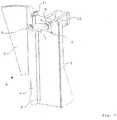
- FIG. 1 shows a door drive 1, which can move a door 2 in a locking position 12 and a release position 13.
- the door leaf 2 is attached to a pivot arm 4, which in turn is connected via a pivot axis 8 with a carrier 3 associated with the door drive 1.
- the door 2 is thereby moved to a release position 13, that the pivot arm 4 from the position shown by the door 2 is pivoted away.
- a pivot lever 5 is provided such that it in turn is pivotable about a drive shaft 9 and engages with a provided at its free end engaging means 7 in a designed as a slot 6 linear guide of the swing arm 4.
- the engagement means 7 moves in the slot 6 both downwards, as well as to the side, so that the pivot arm 4 tracks the predetermined by the pivot lever 5 rotation.
- the pivot arm 4 is moved in an arc about the pivot axis 8 around and the door 2 thus spent from a locking position 12 in a release position 13.
- the pivot arm 4 in this case additionally has a side guide 11, which surrounds a guide edge 18 of the carrier 3 and thereby prevents jumping of the pivot arm 4 of the engagement means 7 of the pivot lever 5.
- the leading edge 18 of the carrier 3 is formed for this purpose according to the arc described by the pivot arm 4. In this way, it is ensured that the side guide 11 always remains in engagement with the edge of the carrier 3.
- this side touching takes on 11 directed against the door pressure force, which is met with an intrusion.
- a division of functions between drive and guide is realized, so that the drive itself does not have to absorb the pressure force.
- a powerless open position of the door drive 1 is realized in that in the case of a power-off, the door is moved along the leading edge 18 due to its gravity in the open position.
- the leading edge 18 has a high point, which can be overcome if necessary in the event of a power failure by means of suitable means, such as a battery-powered auxiliary drive, whereby the door 2 then moves into the open position.
- the drive 10 of the pivot lever 5 is realized by an electric motor, so that an automatic operation of the door drive is made possible.
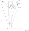
- FIG. 2 again shows the previously illustrated embodiment of the door drive 1, wherein a solid representation corresponds to a locking position 12, while another position of the door drive 1 is shown in dashed lines.
- the door leaf 2 In this second position, the door leaf 2 is in a release position 13, that is, withdrawn from the passageway to which the respective door drive 1 is assigned.
- the engagement means 7 of the pivot lever 5 is located in both extreme positions in each case in the uppermost position of the elongated hole 6, wherein the movement sequence is such that upon rotation of the pivot lever 5, the engagement means 7 initially moves in the slot 6 down, then in an intermediate position reaches the lowest point and then again in the slot 6 moves upward until it again reaches the upper stop, in which the release position 13 is reached.
- the door leaf 2 is shaped in such a way that it substantially corresponds to the area swept by the swivel arm 4, so that the door leaf 2 is flush with the support 3 in the release position 13, so that it is completely withdrawn from the passageway in this position is.
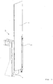
- FIG. 3 shows an embodiment of a door drive 1 according to the invention, which is equipped with a rectangular door leaf 2.
- a rectangular door panel 2 may cover a higher area after a door panel 2 has been replaced in accordance with FIGS FIGS. 1 and 2 in a higher version would have to be shaped such that an upper portion of the door leaf 2 would be very wide, a lower portion, however, would be very narrow. This would release a relatively large opening in the middle between two doors, by which an effective blocking of the area secured by the passage barrier would no longer be guaranteed.
- it makes sense to provide a rectangular door, which ideally should be able to be directly inserted and ejected due to the space required for a pivoting preferred dimensions.
- the door leaf 2 is connected in the corresponding device only at a rotary joint with the pivot arm 4. Characterized in that a connection of the door leaf 2 with the pivot arm 4 is not provided along the entire edge, a detached from the rotational movement of the pivot arm 4 movement form for the door 2 is possible.
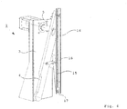
- FIG. 4 shows the door drive 1 according to FIG. 3 , With the door 2 was removed for clarity.
- the pivot arm 4 is associated with an additional support arm 15, which in turn is rotatably mounted on the carrier 3.
- a retaining rail 14 is articulated by means of a slidingly inserted in a linear guide 17 connecting means 16 movable engagement means 7, which is hingedly connected at its other end to the pivot arm 4.
- a connecting means 16 is provided, which is pivotally connected both to the pivot arm 4, and with the support arm 15.
- the pivot arm 4 is moved in the same manner in a forward position, as in connection with the embodiments according to FIGS. 1 and 2 shown, so only the connected to the pivot arm 4 point of the door leaf 2 and the support rail 14, the movement of the swing arm 4 to understand.
- the support arm 15 is pulled behind the pivot arm 4, so that the attached part of the door leaf 2 of the movement of the pivot arm 4 follows, but is offset so that the door 2 is held substantially perpendicular in the course of his movement , This creates the impression of a displacement of the door leaf 2 in a locking position 12, after the caused by the pivot arm 4 slight increase the door leaf 2 with a correspondingly long pivot arm 4 moves only on the edge of the perceptibility.
- FIG. 5 finally shows the door drive 1 in a locking position 12, in which the itself to be provided with a door 2 holding rail 14 has arrived in a forward position.
- the pivot lever 5 is in a stop position in which he holds the pivot arm 4 in turn in a disengaged position. Also in this position, the holding rail 14 is arranged substantially vertically, as it has been previously in the engaged position, ie the release position 13.
- variable door drive which on the one hand solves the problem of creating a sliding effect for the door of a turnstile, which essentially works to save space and on the other makes it possible to different door with one and the same drive unit by minor structural changes use.
Description
- Die vorliegende Erfindung betrifft einen Türantrieb mit einem Träger, an welchem ein mit einem Türflügel verbundener Schwenkarm sowie Stellmittel jeweils drehbar angelenkt sind, wobei die Stellmittel an dem Schwenkarm derart angreifen, dass dieser durch Betätigung der Stellmittel um eine Schwenkachse herum schwenkbar ist.
- Derartige Türantriebe werden beispielsweise für den Einsatz in Durchgangssperren vorgesehen siehe z.B.
DE 20 2005 015 373 U . Solche Durchgangssperren finden an allen Stellen Verwendung, an denen der Durchgang von Personen in einen abgetrennten Bereich oder aus einem abgetrennten Bereich heraus reguliert werden soll. Es sind hierbei verschiedenartige Ausgestaltungen der verwendeten Türelemente bekannt, welche verschiedene Formen, wie etwa rechteckige Formen, dreieckige oder verschiedenartige andere Formen, beinhalten. Die verschiedenen Formen erfordern und ermöglichen hierbei zum Teil unterschiedliche Bewegungsmuster, wodurch jeweils einem bestimmten Türelement auch ein entsprechend angepasster Türantrieb zugeordnet werden muss. - Ebenfalls ist der Konstrukteur eines solchen Türantriebes ergänzend bestrebt, den Türantrieb mit einem möglichst geringen Platzbedarf zu konstruieren. Ideal, da sehr wenig raumgreifend, ist eine Schiebevorrichtung, welche in den Durchgangsweg hineingeschoben bzw. herausgezogen wird, wodurch der Weg gesperrt bzw. wieder freigegeben wird. Jedoch besteht hierbei das Problem, dass die Schienenführung einer solchen Schiebetür relativ wartungs- und reparaturanfällig ist, wodurch eine derartige Lösung für den Hersteller von Türantrieben eher uninteressant erscheint.
- Vor diesem Hintergrund liegt der vorliegenden Erfindung die Aufgabe zugrunde, einen Türantrieb zu schaffen, welcher ebenfalls mit sehr wenig Platzbedarf auskommt, aber dennoch auf die Verwendung einer Schienenführung verzichtet. Ferner soll ein solcher Türantrieb es erlauben, verschiedene Formen von Türflügeln mit ein und demselben Antrieb zu verwenden.
- Dies gelingt durch einen Türantrieb gemäß den Merkmalen des Anspruchs 1. Weitere sinnvolle Ausgestaltungen des erfindungsgemäßen Türantriebs können den Unteransprüchen entnommen werden.
- Erfindungsgemäß weist ein Türantrieb einen Träger auf, welcher im Wesentlichen als Rahmen der Konstruktion anzusehen ist. Der Träger ist mit einem Schwenkarm ausgestattet, welcher dem Träger über ein Drehgelenk zugeordnet ist. Auf diese Weise ist der Schwenkarm an dem Träger hin- und herschwenkbar. Die Verschwenkung des Schwenkarm wird mithilfe von Stellmitteln geleistet, welche in unterschiedlichen Ausgestaltungen denkbar sind. So ist eine bevorzugte Ausgestaltungsform des Stellmittels ein Schwenkhebel, welcher seinerseits dem Träger drehbar zugeordnet ist. In diesem Fall sind dem Schwenkhebel ferner Antriebsmittel zugeordnet, welche den Schwenkhebel in einem Halbkreis um eine Antriebsachse herum verdrehen können. Das freie Ende des Schwenkhebels greift in eine Linearführung des Schwenkarms ein, welche beispielsweise in Form eines Langlochs realisiert sein kann, so dass die freien Enden der beiden Schwenkelemente derart miteinander verbunden sind, dass eine Drehung des Schwenkhebels in einer Vor- und Zurückbewegung des Schwenkarms umgesetzt wird. Der Schwenkhebel weist an seinem Ende ein Eingreifmittel auf, je nach Ausgestaltung der Linearführung etwa in Form einer gleitenden Rolle oder auch eines kugelgelagerten Schlittens, so dass dieses Eingreifmittel gleitend in der Linearführung aufgenommen ist. Wäre der Schwenkhebel mit dem Schwenkarm über eine Gelenkverbindung verbunden, so wäre die hierdurch entstehende Verbindung in einer vorgegebenen Position festgelegt. Aufgrund der Vorsehung einer Linearführung und der gleitenden Aufnahme des Eingreifmittels daran ist es möglich, dass die rotatorische Bewegung des Schwenkhebels in eine Vor- und Zurückbewegung des Schwenkarms umgesetzt werden kann - ein an dem Schwenkarm befestigtes Türelement wird somit für den Betrachter in den Durchgangsweg hineingeschoben bzw. aus diesem Weg herausgezogen, gleichsam so, als würde es sich um eine Schiebetür handeln. Es wird daher lediglich an Platzbedarf der Raum für das Türelement selbst, sowie für den Schwenkarm erfordert, der mit dem Türelement selbst verbunden ist. An dem Schwenkarm können Türelemente verschiedener Formen montiert werden.
- Das Langloch dient in diesem Zusammenhang dazu, die Schwenkbewegung des Schwenkhebels zu begrenzen. Die Rotation des Schwenkhebels endet an der Stelle, an der das Eingreifelement bis zum Anschlag der Linearführung geführt worden ist, wobei Schwenkarm und Schwenkhebel derart zueinander ausgerichtet sind, dass diese Position eine vordere Auslenkposition des Türelementes darstellt. In dieser vorderen Auslenkposition des Türelementes befindet sich dieses in einer Sperrposition. Durch ein Verdrehen des Schwenkelementes in die Gegenrichtung bewegt sich das Eingreifelement in der Linearführung zunächst in eine tiefste Position und sodann zurück in die vorher genannte Anschlagsposition, die in diesem Fall wiederum den Anschlag in der hinteren Anschlagsposition des Türelementes bildet. In dieser hinteren Anschlagsposition des Türelementes befindet sich dieses in einer Freigabeposition.
- Alternativ, jedoch nicht erfindungsgemäß, zu dem Schwenkhebel kann auch ein Linearantrieb oder ein Kolbenantrieb, etwa in Form eines Hydraulikzylinders, vorgesehen sein, welcher ebenfalls an dem Träger drehbar aufgehängt ist und mit seinem freien Ende mit dem Schwenkarm gelenkig verbunden ist.
- In einer ersten, nicht erfindungsgemäßen Ausgestaltungsform ist der Türflügel entlang einer Befestigungskante mit dem Schwenkarm verbunden, somit also mit diesem unbeweglich zusammengefügt. Das Türelement, bzw. der Türflügel, folgt somit exakt der Bewegung des Schwenkarms. Für eine derartige Anordnung eignet sich insbesondere die Form des Dreiecks für den Türflügel, so dass der Türflügel im Wesentlichen den von dem Schwenkarm übergriffenen Raumbereich im Laufe eines Bewegungsablaufs ausfüllt. Aufgrund dieser Form wird der Türflügel in seiner Freigabeposition den Durchgangsweg vollständig freigeben, trotzdem der Türflügel in einer Schwenkbewegung aus dem Durchgangsweg herausbewegt wird.
- In einer Ausgestaltungsform der Erfindung ist jedoch dem Türantrieb ein zusätzlicher Stützarm zugeordnet, welcher ebenfalls dem Träger gelenkig anverbunden ist. Der Türflügel ist in diesem Fall dem Schwenkarm lediglich in einem Drehgelenk punktförmig anverbunden, wodurch er gegenüber dem Schwenkarm verdrehbar ist. In einem zweiten Punkt ist der Türflügel an dem Stützarm befestigt, so dass der Türflügel definiert gehalten ist. Der Vorteil dieser Anordnung liegt darin, dass der Türflügel auf diese Art und Weise im Wesentlichen stets senkrecht gehalten werden kann, nachdem er die Drehbewegung des Schwenkarms nicht notwendiger Weise mit ausführen muss. Dies kann zudem dadurch unterstützt werden, dass der Stützarm zusätzlich gelenkig mit dem Schwenkarm verbunden wird, so dass die Bewegung des Schwenkarms auch auf den Stützarm übertragen wird. Wird ferner eine weitere Linearführung zur Befestigung des Türflügels an dem Stützarm eingesetzt, in welche ein Eingreifmittel des Stützarms gleitend eingreift, so kann die Bewegung des Schwenkarms derart auf den Stützarm übertragen werden, dass eine nahezu parallele Verschiebung der Hinterkante des Türelementes realisiert werden kann.
- Insoweit eignet sich hier insbesondere auch die rechteckige Form eines Türflügels, nachdem eine im Wesentlichen parallel verschobene Hinterkante des Türflügels dazu führt, dass der Effekt einer Schiebetür zumindest weitgehend nachempfunden wird.
- Der Türflügel muss mithin nicht direkt mit dem Schwenkarm bzw. dem Stützarm verbunden sein; vielmehr ist es möglich, eine Halteschiene vorzusehen, welche die entsprechenden Befestigungsmittel aufweist. Diese Halteschiene kann dann ihrerseits mit dem Türflügel verbunden sein, so dass auf diese Art und Weise der Türflügel bei Bedarf ohne Weiteres austauschbar ist.
- Eine zusätzliche seitliche Führung der Türflügel kann dadurch realisiert werden, dass dem Schwenkarm eine Seitenführung zugeordnet ist, welche eine Führungskante des Trägers umgreift. Hierzu ist die entsprechende Kante dem Bewegungsmuster des Schwenkarms angepasst, so dass die Seitenführung stets in Eingriff mit der Führungskante ist. Die Führungskante kann dabei einen Hochpunkt aufweisen, welcher den Punkt der größten Hebung der Tür markiert. Hierdurch ist es möglich, dass die Tür nach einem Überschreiten dieses Hochpunkts aufgrund ihrer Lageenergie selbsttätig in eine Stromlosstellung läuft. Es kann zur definierten Positionierung der Tür etwa im Fall eines Stromausfalls auch ein zusätzliches Mittel zur Überwindung des Hochpunkts zugeordnet werden, so dass dafür Sorge getragen ist, dass die Tür in diesem Fall stets die erwartete Position einnimmt. In diesem Zusammenhang ist es auch möglich, den Hochpunkts mittig bezüglich der Führungskante anzuordnen, so dass zwischen einer Stromlos-Offen-Stellung und einer Stromlos-Geschlossen-Stellung gewählt werden kann, indem die Mittel zur Überwindung des Hochpunkts in die eine und in die andere Richtung betreibbar sind. Im übrigen kann ein Türantrieb durch einfaches Umdrehen von einem Stromlos-Offen-Betrieb in einen Stromlos-Geschlossen-Betrieb umgewidmet werden. Eine gesonderte Konstruktion ist hierfür nicht erforderlich.
- Eine Tür, welche als Durchtrittssperre eingesetzt wird, muss eine gewisse Kraft aufbringen, die dem Versuch, sie zu öffnen, entgegengebracht wird. Diese wird in einer einfachen Ausgestaltungsform lediglich von dem Antrieb des Schwenkarms aufgebracht, welche allerdings dadurch verstärkt werden kann, dass ein Haftmagnet zwischen dem Schwenkarm und dem Träger oder zwischen Schwenkhebel und Träger angeordnet wird, der die Tür in ihrer Geschlossenstellung aufgrund zusätzlicher magnetischer Energie in ihrer Position hält.
- Die vorstehend beschriebene Erfindung wird im Folgenden anhand eines Ausführungsbeispiels näher erläutert.
- Es zeigen
- Fig. 1:
- eine erste nicht erfindungsgemäße Ausführungsform mit einem entlang einer Befestigungskante mit dem Schwenkarm verbundenen Türflügel in einer perspektivischen Darstellung von schräg oben,
- Fig. 2:
- der Türantrieb gemäß
Fig. 1 in einer frontalen Draufsicht, wobei neben der Sperrposition des Türflügels auch eine Freigabeposition des Türflügels angedeutet ist, - Fig. 3:
- eine Ausführungsform der Erfindung mit einer Zweipunktaufhängung eines rechteckigen Türflügels in einer perspektivischen Ansicht von schräg oben,
- Fig. 4:
- der Türantrieb gemäß
Fig. 3 , bei welchem der Türflügel entfernt wurde, in einer Freigabeposition, sowie - Fig. 5:
- der Türantrieb gemäß
Fig. 4 in einer Sperrposition. -
Figur 1 zeigt einen Türantrieb 1, welcher einen Türflügel 2 in eine Sperrposition 12 und eine Freigabeposition 13 bewegen kann. Hierzu ist der Türflügel 2 an einem Schwenkarm 4 befestigt, welcher seinerseits über eine Schwenkachse 8 mit einem dem Türantrieb 1 zugeordneten Träger 3 verbunden ist. Der Türflügel 2 wird dadurch in eine Freigabeposition 13 verbracht, dass der Schwenkarm 4 aus der gezeigten Position heraus von dem Türflügel 2 weg verschwenkt wird. Dies wird geleistet, indem ein Schwenkhebel 5 derart vorgesehen ist, dass er seinerseits um eine Antriebsachse 9 verschwenkbar ist und mit einem an seinem freien Ende vorgesehenen Eingreifmittel 7 in eine als Langloch 6 ausgeführte Linearführung des Schwenkarms 4 eingreift. Durch eine Rotation des Schwenkarms 4 bewegt sich das Eingreifmittel 7 in dem Langloch 6 sowohl nach unten, als auch zur Seite hin, so dass der Schwenkarm 4 die von dem Schwenkhebel 5 vorgegebene Drehung nachvollzieht. Auf diese Weise wird der Schwenkarm 4 in einem Bogen um die Schwenkachse 8 herum bewegt und der Türflügel 2 somit aus einer Sperrposition 12 in eine Freigabeposition 13 verbracht. Der Schwenkarm 4 weist hierbei zusätzlich eine Seitenführung 11 auf, welche eine Führungskante 18 des Trägers 3 umgreift und hierdurch ein Abspringen des Schwenkarms 4 von dem Eingreifmittel 7 des Schwenkhebels 5 verhindert. Die Führungskante 18 des Trägers 3 ist hierfür gemäß dem von dem Schwenkarm 4 beschriebenen Bogen geformt. Auf diese Weise ist sichergestellt, dass die Seitenführung 11 stets in Eingriff mit der Kante des Trägers 3 verbleibt. Zudem nimmt diese Seitenrührung 11 gegen die Tür gerichtete Druckkraft auf, welche einem Eindringen entgegengebracht wird. Dadurch ist eine Funktionsteilung zwischen Antrieb und Führung realisiert, so dass der Antrieb selbst nicht die Druckkraft abfedern muss. Ferner ist eine Stromlos-Offen-Stellung des Türantriebs 1 dadurch realisiert, dass im Fall einer Stromlosschaltung die Tür entlang der Führungskante 18 aufgrund ihrer Schwerkraft in die Offenstellung verschoben wird. Hierzu weist die Führungskante 18 einen Hochpunkts auf, welcher bei Bedarf im Falle eines Stromausfalls mithilfe geeigneter Mittel, etwa eines batteriebetriebenen Hilfsantriebs, überwunden werden kann, wodurch sich der Türflügel 2 sodann in die Offenstellung verschiebt. Der Antrieb 10 des Schwenkhebels 5 ist durch einen Elektromotor realisiert, so dass eine automatische Bedienung des Türantriebs ermöglicht ist. -
Figur 2 zeigt erneut die zuvor dargestellte Ausführungsform des Türantriebs 1, wobei eine durchgezogene Darstellung einer Sperrposition 12 entspricht, während eine weitere Stellung des Türantriebs 1 mit gestrichelten Linien dargestellt ist. In dieser zweiten Stellung befindet sich der Türflügel 2 in einer Freigabeposition 13, ist also aus dem Durchgangsweg, welchem der jeweilige Türantrieb 1 zugeordnet ist, zurückgezogen. Das Eingreifmittel 7 des Schwenkhebels 5 befindet sich in beiden Extrempositionen jeweils in der obersten Position des Langloches 6, wobei der Bewegungsablauf derart ist, dass bei einer Drehung des Schwenkhebels 5 das Eingreifmittel 7 zunächst in dem Langloch 6 nach unten wandert, dann in einer Zwischenstellung den tiefsten Punkt erreicht und danach wieder in dem Langloch 6 nach oben wandert, bis er erneut den oberen Anschlag erreicht, in welchem die Freigabeposition 13 erreicht ist. Der Türflügel 2 ist der Form nach derart gestaltet, dass er dem von dem Schwenkarm 4 überstrichenen Bereich im Wesentlichen entspricht, so dass der Türflügel 2 in der Freigabeposition 13 bündig mit dem Träger 3 abschließt, so dass er in dieser Position vollständig aus dem Durchgangsweg zurückgezogen ist. -
Figur 3 zeigt eine Ausführungsform eines erfindungsgemäßen Türantriebs 1, welche mit einem rechteckigen Türflügel 2 ausgestattet ist. Ein rechteckiger Türflügel 2 kann beispielsweise einen höheren Bereich abdecken, nachdem ein Türflügel 2 gemäß denFiguren 1 und2 in einer höheren Ausführung derart geformt sein müssten, dass ein oberer Bereich des Türflügels 2 sehr breit, ein unterer Bereich hingegen sehr schmal wäre. Dies würde eine relativ große Öffnung in der Mitte zwischen zwei Türen freigeben, durch welche eine wirksame Absperrung des durch die Durchgangssperre gesicherten Bereichs nicht mehr gewährleistet wäre. Insoweit ist es sinnvoll, eine rechteckige Tür vorzusehen, welche idealerweise aufgrund des erforderlichen Platzbedarfs für eine Verschwenkung bevorzugtermaßen direkt ein- und ausgeschoben werden können soll. Hierzu ist der Türflügel 2 in der entsprechenden Vorrichtung lediglich an einem Drehgelenk mit dem Schwenkarm 4 verbunden. Dadurch, dass eine Verbindung des Türflügels 2 mit dem Schwenkarm 4 nicht entlang der gesamten Kante vorgesehen ist, ist eine von der Drehbewegung des Schwenkarms 4 losgelöste Bewegungsform für die Türflügel 2 möglich. -
Figur 4 zeigt den Türantrieb 1 gemäßFigur 3 , wobei der Türflügel 2 zur besseren Übersicht entfernt wurde. In dieser Ausgestaltungsform ist dem Schwenkarm 4 ein zusätzlicher Stützarm 15 zugeordnet, welcher seinerseits an dem Träger 3 drehbar angeordnet ist. An diesem Stützarm 15 ist eine Halteschiene 14 mittels eines in einer Linearführung 17 gleitend eingefügte Verbindungsmittel 16 beweglichen Eingreifmittel 7 mit angelenkt, welche an ihrem anderen Ende mit dem Schwenkarm 4 gelenkig verbunden ist. In der Halteschiene 14 ist der Türflügel 2 befestigbar, was die Befestigung des Türflügels an dem Schwenkarm 4 zudem erleichtert. Um nun die Bewegung des Schwenkarms 4 auf den Stützarm 15 zu übertragen, ist ein Verbindungsmittel 16 vorgesehen, welches sowohl mit dem Schwenkarm 4, als auch mit dem Stützarm 15 gelenkig verbunden ist. Wird nun der Schwenkarm 4 auf die gleiche Weise in eine vordere Position bewegt, wie im Zusammenhang mit den Ausgestaltungsformen nachFiguren 1 und2 gezeigt, so wird lediglich der mit dem Schwenkarm 4 verbundene Punkt des Türflügels 2 bzw. der Halteschiene 14 die Bewegung des Schwenkarms 4 nachvollziehen. Aufgrund des Verbindungsmittels 16 wird der Stützarm 15 jedoch hinter dem Schwenkarm 4 hergezogen, so dass der hieran befestigte Teil des Türflügels 2 der Bewegung des Schwenkarms 4 zwar folgt, jedoch so versetzt ist, dass der Türflügel 2 im Laufe seines Bewegungsablaufes im Wesentlichen senkrecht gehalten wird. Hierdurch entsteht der Eindruck eines Verschiebens des Türflügels 2 in eine Sperrposition 12, nachdem die durch den Schwenkarm 4 verursachte leichte Anhebung des Türflügels 2 mit einem entsprechend langen Schwenkarm 4 sich nur noch am Rande der Wahrnehmbarkeit bewegt. -
Figur 5 zeigt schließlich den Türantrieb 1 in einer Sperrposition 12, in welcher die an sich mit einem Türflügel 2 zu versehende Halteschiene 14 in einer vorderen Position angelangt ist. Der Schwenkhebel 5 befindet sich dabei in einer Anschlagposition, in der er den Schwenkarm 4 seinerseits in einer Ausrückposition hält. Auch in dieser Position ist die Halteschiene 14 im Wesentlichen senkrecht angeordnet, so wie es auch zuvor in der eingerückten Position, also der Freigabeposition 13, gewesen ist. - Es ist aufgrund der zuvor beschriebenen Figuren durchaus sichtbar, dass durch eine geringe bauliche Änderung, nämlich dem Einzufügen eines Stützarm 15 und des entsprechenden Verbindungsmittels 16, der Türantrieb 1 gemäß den
Figuren 1 und2 zu einem erfindungsgemäßen Türantrieb 1 der Ausgestaltungsform nachFiguren 3 bis 5 für einen anderen Türflügel 2 vorsehbar ist. - Vorstehend ist somit ein variabler Türantrieb beschrieben, welcher zum Einen die Problematik löst, einen Schiebeeffekt für die Türflügel einer Drehsperre zu erzeugen, welcher im Wesentlichen besonders platzsparend funktioniert und der es zum Anderen ermöglicht, verschiedene Türflügel mit ein und derselben Antriebseinheit durch geringfügige bauliche Änderungen zu benutzen.
-
- 1.
- Türantrieb
- 2.
- Türflügel
- 3.
- Träger
- 4.
- Schwenkarm
- 5.
- Schwenkhebel
- 6.
- Langloch
- 7.
- Eingreifmittel
- 8.
- Schwenkachse
- 9.
- Antriebsachse
- 10.
- Antrieb
- 11.
- Seitenführung
- 12.
- Sperrposition
- 13.
- Freigabeposition
- 14.
- Halteschiene
- 15.
- Stützarm
- 16.
- Verbindungsmittel
- 17.
- Linearführung
- 18.
- Führungskante
Claims (10)
- Türantrieb mit einem Träger (3), an welchem ein mit einem Türflügel (2) verbundener Schwenkarm (4) sowie Stellmittel jeweils drehbar angelenkt sind, wobei die Stellmittel an dem Schwenkarm (4) derart angreifen, dass dieser durch Betätigung der Stellmittel um eine Schwenkachse (8) herum schwenkbar ist, wobei die Stellmittel einen Schwenkhebel (5) umfassen, welcher mittels dem Träger (3) zugeordneter Antriebsmittel (10) um eine Antriebsachse (9) herum schwenkbar ist, wobei ein freies Ende des Schwenkhebels (5) Eingreifmittel (7) aufweist, welche in eine Linearführung des Schwenkarms (4) gleitend eingreifen, dadurch gekennzeichnet, dass der Türflügel (2) eine Zweipunktaufhängung aufweist, wobei der Türflügel (2) dem Schwenkarm (4) und einem an den Träger (3) drehbar angelenkten Stützarm (15) jeweils gelenkig anverbunden ist.
- Türantrieb gemäß Anspruch 1, dadurch gekennzeichnet, dass der Stützarm (15) Verbindungsmittel (16) aufweist, welche mit dem Schwenkarm (4) und dem Stützarm (15) gelenkig verbunden sind, wobei die Verbindung zwischen Türflügel (2) und Stützarm (15) durch ein in eine Linearführung (17) des Türflügels (2) gleitend eingreifendes Eingreifmittel hergestellt ist.
- Türantrieb gemäß einem der vorhergehenden Ansprüche, dadurch gekennzeichnet, dass der Türflügel (2) im Wesentlichen rechteckig ist.
- Türantrieb gemäß einem der vorhergehenden Ansprüche, dadurch gekennzeichnet, dass der Türflügel (2) von einer Halteschiene (14) gehalten ist, welche die Befestigung mit dem Schwenkarm (14) bzw. dem Stützarm (15) realisiert.
- Türantrieb gemäß einem der vorhergehenden Ansprüche, dadurch gekennzeichnet, dass dem Schwenkarm (4) und/oder der Halteschiene (14) wenigstens eine Seitenführung (11) zugeordnet ist, welche eine dem Bewegungsbild des Schwenkarms (4) angepasste Führungskante (18) des Trägers (3) umgreift und entlang dieser verschieblich ist.
- Türantrieb gemäß Anspruch 5, dadurch gekennzeichnet, dass die wenigstens eine Führungskante (18) des Trägers (3) einen Hochpunkt aufweist und dem Türantrieb Mittel zur Überwindung des Hochpunkts im Falle einer Stromlosschaltung zugeordnet sind.
- Türantrieb gemäß Anspruch 6, dadurch gekennzeichnet, dass der Hochpunkt der wenigstens einen Führungskante (18) bezüglich dieser im Wesentlichen mittig angeordnet ist.
- Türantrieb gemäß einem der vorhergehenden Ansprüche, dadurch gekennzeichnet, dass als Antriebsmittel (10) ein Elektromotor zum Drehantrieb des Schwenkhebels (5) vorgesehen ist.
- Türantrieb gemäß einem der vorhergehenden Ansprüche, dadurch gekennzeichnet, dass in einer Geschlossenstellung des Türflügels (2) zwischen Träger (3) und Schwenkarm (4) ein Haftmagnet wirkt.
- Durchgangssperre mit zwei einander gegenüberliegend angeordneten Türantrieben (1) gemäß einem der vorhergehenden Ansprüche.
Applications Claiming Priority (3)
| Application Number | Priority Date | Filing Date | Title |
|---|---|---|---|
| DE102008021147 | 2008-04-28 | ||
| DE102008025757A DE102008025757A1 (de) | 2008-04-28 | 2008-05-29 | Türantrieb |
| PCT/DE2009/075012 WO2009132644A1 (de) | 2008-04-28 | 2009-03-12 | Türantrieb |
Publications (3)
| Publication Number | Publication Date |
|---|---|
| EP2297421A1 EP2297421A1 (de) | 2011-03-23 |
| EP2297421B1 EP2297421B1 (de) | 2015-08-12 |
| EP2297421B2 true EP2297421B2 (de) | 2019-06-19 |
Family
ID=41111911
Family Applications (1)
| Application Number | Title | Priority Date | Filing Date |
|---|---|---|---|
| EP09737752.7A Active EP2297421B2 (de) | 2008-04-28 | 2009-03-12 | Türantrieb |
Country Status (7)
| Country | Link |
|---|---|
| EP (1) | EP2297421B2 (de) |
| CN (1) | CN102016215B (de) |
| DE (1) | DE102008025757A1 (de) |
| ES (1) | ES2546947T3 (de) |
| HK (1) | HK1155500A1 (de) |
| MY (1) | MY159223A (de) |
| WO (1) | WO2009132644A1 (de) |
Families Citing this family (12)
| Publication number | Priority date | Publication date | Assignee | Title |
|---|---|---|---|---|
| DE202009005241U1 (de) | 2009-09-07 | 2009-12-10 | Kaba Gallenschütz GmbH | Durchgangssperre |
| CN103835245B (zh) * | 2012-11-23 | 2016-07-06 | 北京中软万维网络技术有限公司 | 地铁闸机剪式门 |
| CN103225464B (zh) * | 2013-05-10 | 2015-12-30 | 浙江众合科技股份有限公司 | 一种闸机通行控制机构 |
| CN103352439A (zh) * | 2013-07-19 | 2013-10-16 | 浙江众合机电股份有限公司 | 一种闸机剪式门机构 |
| FR3069867B1 (fr) | 2017-08-01 | 2021-04-09 | Thales Sa | Ensemble de portillons automatiques comprenant des ensembles moteurs sensiblement identiques et procede de production d'un tel ensemble |
| WO2020065433A1 (en) * | 2018-09-24 | 2020-04-02 | Gunnebo Entrance Control Ltd. | Wing gate turnstiles |
| DE102018125462A1 (de) | 2018-10-15 | 2020-04-16 | Dormakaba Deutschland Gmbh | Durchgangssperre sowie ein Verfahren zur Herstellung einer Durchgangssperre |
| DE102018125455A1 (de) | 2018-10-15 | 2020-04-16 | Dormakaba Deutschland Gmbh | Durchgangssperre |
| DE102018125473B4 (de) | 2018-10-15 | 2022-07-28 | Dormakaba Deutschland Gmbh | Durchgangssperre sowie ein Verfahren zur Herstellung einer Durchgangssperre |
| DE102018125448B4 (de) | 2018-10-15 | 2022-07-28 | Dormakaba Deutschland Gmbh | Durchgangssperre |
| DE102018125483B4 (de) | 2018-10-15 | 2022-07-28 | Dormakaba Deutschland Gmbh | Durchgangssperre sowie ein Verfahren zur Herstellung einer Durchgangssperre |
| DE102021111684A1 (de) * | 2021-05-05 | 2022-11-10 | Magnetic Autocontrol Gmbh | Personensperre und Sperrvorrichtung für eine solche |
Family Cites Families (21)
| Publication number | Priority date | Publication date | Assignee | Title |
|---|---|---|---|---|
| US802270A (en) | 1905-04-27 | 1905-10-17 | Hardin Deaderick | Furnace-door operator. |
| GB191317942A (en) | 1912-04-09 | 1914-02-12 | Arno Hoehne | Improvements in or relating to Means for Opening and Closing Doors. |
| US1339671A (en) | 1912-10-16 | 1920-05-11 | Nat Pneumatic Co | Power-operated mechanism for moving doors or the like |
| US3478467A (en) | 1967-05-03 | 1969-11-18 | Ibm | Fare operated gate assembly |
| DE2507967A1 (de) | 1968-12-12 | 1976-09-02 | Kauffmann Maschbau Herbert | Drehfalttor |
| DE2751859A1 (de) | 1977-11-21 | 1979-05-23 | Dorma Baubeschlag | Tuerschliesser |
| DE4304371B4 (de) | 1992-06-12 | 2004-09-23 | Geze Gmbh | Antrieb zum Öffnen und/oder Schließen einer Pendeltür |
| IT1272644B (it) | 1993-09-16 | 1997-06-26 | Italdis Ind Spa | Dispositivo di movimentazione di ante scorrevoli |
| DE19840766A1 (de) | 1998-09-07 | 2000-03-09 | Geze Gmbh | Antrieb für einen Flügel einer Tür, eines Fensters oder dergleichen |
| DE20301951U1 (de) | 2003-02-07 | 2004-06-09 | Liebherr-Hausgeräte Ochsenhausen GmbH | Türöffnungshilfe |
| FR2855209B1 (fr) * | 2003-05-23 | 2005-07-01 | Gilles Labardin | Portail a elements repliables |
| CN100383342C (zh) * | 2004-02-25 | 2008-04-23 | 上海华虹计通智能卡系统有限公司 | 自动扇门阻挡机构 |
| ITVI20050164A1 (it) | 2005-05-31 | 2006-12-01 | Gunnebo Entrance Control Spa | Dispositivo di sicurezza per varchi di accesso motorizzati |
| WO2007028401A1 (fr) | 2005-09-05 | 2007-03-15 | Automatic Systems | Obstacle mobile a double volet, notamment a volet sectoriel, portillon ainsi equipe |
| DE202005015373U1 (de) | 2005-09-29 | 2005-12-15 | Magnetic Autocontrol Gmbh | Sperrelement, insbesondere für eine Durchgangssperre |
| ITVI20060022A1 (it) | 2006-01-20 | 2007-07-21 | Gunnebo Entrance Control Spa | Sistema di protezione per varchi pedonali di accesso motorizzati |
| CN101012726B (zh) | 2006-03-31 | 2010-07-28 | 上海邮电通信设备股份有限公司 | 一种扇形门闸机的阻挡机构 |
| CN2937405Y (zh) | 2006-08-15 | 2007-08-22 | 上海盛卡恩智能系统有限公司 | 伸缩门门禁控制装置 |
| CN100999974B (zh) | 2007-01-08 | 2010-05-26 | 上海盛卡恩智能系统有限公司 | 宽通道双门伸缩机构 |
| CN201011292Y (zh) | 2007-01-08 | 2008-01-23 | 上海盛卡恩智能系统有限公司 | 宽通道双门伸缩机构 |
| CN201037352Y (zh) | 2007-06-05 | 2008-03-19 | 上海华铭智能终端设备有限公司 | 一种自动检票机剪式门装置 |
-
2008
- 2008-05-29 DE DE102008025757A patent/DE102008025757A1/de not_active Withdrawn
-
2009
- 2009-03-12 EP EP09737752.7A patent/EP2297421B2/de active Active
- 2009-03-12 CN CN2009801150747A patent/CN102016215B/zh active Active
- 2009-03-12 WO PCT/DE2009/075012 patent/WO2009132644A1/de active Application Filing
- 2009-03-12 MY MYPI2010005053A patent/MY159223A/en unknown
- 2009-03-12 ES ES09737752.7T patent/ES2546947T3/es active Active
-
2011
- 2011-08-15 HK HK11108511.0A patent/HK1155500A1/xx unknown
Also Published As
| Publication number | Publication date |
|---|---|
| MY159223A (en) | 2016-12-30 |
| HK1155500A1 (en) | 2012-05-18 |
| EP2297421A1 (de) | 2011-03-23 |
| WO2009132644A1 (de) | 2009-11-05 |
| CN102016215B (zh) | 2013-12-04 |
| CN102016215A (zh) | 2011-04-13 |
| DE102008025757A1 (de) | 2009-10-29 |
| EP2297421B1 (de) | 2015-08-12 |
| ES2546947T3 (es) | 2015-09-30 |
Similar Documents
| Publication | Publication Date | Title |
|---|---|---|
| EP2297421B2 (de) | Türantrieb | |
| EP2475834B1 (de) | Durchgangssperre | |
| EP3612696A1 (de) | Türgriffanordnung für ein kraftfahrzeug | |
| EP2362041B1 (de) | Minenschutzverriegelung zur Anordnung an Türen von militärischen Fahrzeugen | |
| DE102005033098B4 (de) | Heckklappe für ein Kraftfahrzeug | |
| EP2626491B1 (de) | Beschlaganordnung | |
| EP2133494B1 (de) | Sicherheitsverriegelungsvorrichtung mit Fluchtentriegelungseinrichtung | |
| EP3027828A1 (de) | Kraftfahrzeugtür | |
| EP3277899B1 (de) | Türgriffanordnung für ein kraftfahrzeug | |
| DE102008047046B4 (de) | Türantrieb für eine Schwenkschiebetür eines Fahrzeugs | |
| DD219985A5 (de) | Ausschwingtuer mit betaetigungseinrichtung | |
| DE19725677C2 (de) | Fenster oder Tür an Wohnwagen, Wohnmobilen oder sonstigen Fahrzeugen, mit Verriegelungseinrichtungen mit gemeinsamer Betätigungshandhabe | |
| DE102009004498B4 (de) | Türanordnung mit einer Schließfolgeregelung | |
| DE102012111095A1 (de) | Schwenkhebelverschluss mit geringer Einbautiefe | |
| EP1022421A2 (de) | Ausstellvorrichtung für einen an einem Rahmen schwenkbar angebrachten Kipp- oder Dreh-Kipp-Flügel | |
| DE202011004196U1 (de) | Verschlussvorrichtung | |
| DE102016210168B3 (de) | Türantrieb für eine Kraftwagentür | |
| AT414115B (de) | Bodenverriegelung | |
| DE102009050875B4 (de) | Vorrichtung zum Öffnen und Schließen von Fenstern an Wohnwagen, Wohnmobilen und dergleichen | |
| EP1970508A2 (de) | Vorrichtung zur Arretierung eines schwenkbaren Bauteiles eines Kraftfahrzeuges | |
| DE3503806C2 (de) | ||
| DE10257688A1 (de) | Verschussvorrichtung für eine in einem Fahrzeug vorgesehene Öffnung mit einer einzigen Gleitführungsschiene sowie entsprechendes Fahrzeug | |
| EP1149974A1 (de) | Feststellvorrichtung | |
| EP1170445A2 (de) | Ausstellvorrichtung für einen an einem Rahmen schwenkbar angebrachten Kipp- oder Dreh-Kipp-Flügel | |
| DE102008028598A1 (de) | Insektenschutztür |
Legal Events
| Date | Code | Title | Description |
|---|---|---|---|
| PUAI | Public reference made under article 153(3) epc to a published international application that has entered the european phase |
Free format text: ORIGINAL CODE: 0009012 |
|
| 17P | Request for examination filed |
Effective date: 20101112 |
|
| AK | Designated contracting states |
Kind code of ref document: A1 Designated state(s): AT BE BG CH CY CZ DE DK EE ES FI FR GB GR HR HU IE IS IT LI LT LU LV MC MK MT NL NO PL PT RO SE SI SK TR |
|
| AX | Request for extension of the european patent |
Extension state: AL BA RS |
|
| DAX | Request for extension of the european patent (deleted) | ||
| GRAP | Despatch of communication of intention to grant a patent |
Free format text: ORIGINAL CODE: EPIDOSNIGR1 |
|
| REG | Reference to a national code |
Ref country code: DE Ref legal event code: R079 Ref document number: 502009011411 Country of ref document: DE Free format text: PREVIOUS MAIN CLASS: E05F0015120000 Ipc: E05F0015630000 |
|
| INTG | Intention to grant announced |
Effective date: 20150310 |
|
| RIC1 | Information provided on ipc code assigned before grant |
Ipc: E06B 11/02 20060101ALI20150312BHEP Ipc: E05F 15/611 20150101ALI20150312BHEP Ipc: E05F 15/63 20150101AFI20150312BHEP |
|
| GRAS | Grant fee paid |
Free format text: ORIGINAL CODE: EPIDOSNIGR3 |
|
| GRAA | (expected) grant |
Free format text: ORIGINAL CODE: 0009210 |
|
| AK | Designated contracting states |
Kind code of ref document: B1 Designated state(s): AT BE BG CH CY CZ DE DK EE ES FI FR GB GR HR HU IE IS IT LI LT LU LV MC MK MT NL NO PL PT RO SE SI SK TR |
|
| REG | Reference to a national code |
Ref country code: GB Ref legal event code: FG4D Free format text: NOT ENGLISH |
|
| REG | Reference to a national code |
Ref country code: CH Ref legal event code: EP |
|
| REG | Reference to a national code |
Ref country code: AT Ref legal event code: REF Ref document number: 742333 Country of ref document: AT Kind code of ref document: T Effective date: 20150815 |
|
| REG | Reference to a national code |
Ref country code: IE Ref legal event code: FG4D Free format text: LANGUAGE OF EP DOCUMENT: GERMAN |
|
| REG | Reference to a national code |
Ref country code: DE Ref legal event code: R096 Ref document number: 502009011411 Country of ref document: DE |
|
| REG | Reference to a national code |
Ref country code: CH Ref legal event code: NV Representative=s name: OFFICE ERNEST T. FREYLINGER S.A., CH Ref country code: ES Ref legal event code: FG2A Ref document number: 2546947 Country of ref document: ES Kind code of ref document: T3 Effective date: 20150930 |
|
| REG | Reference to a national code |
Ref country code: SE Ref legal event code: TRGR |
|
| REG | Reference to a national code |
Ref country code: LT Ref legal event code: MG4D |
|
| REG | Reference to a national code |
Ref country code: NL Ref legal event code: FP |
|
| PG25 | Lapsed in a contracting state [announced via postgrant information from national office to epo] |
Ref country code: LV Free format text: LAPSE BECAUSE OF FAILURE TO SUBMIT A TRANSLATION OF THE DESCRIPTION OR TO PAY THE FEE WITHIN THE PRESCRIBED TIME-LIMIT Effective date: 20150812 Ref country code: LT Free format text: LAPSE BECAUSE OF FAILURE TO SUBMIT A TRANSLATION OF THE DESCRIPTION OR TO PAY THE FEE WITHIN THE PRESCRIBED TIME-LIMIT Effective date: 20150812 Ref country code: FI Free format text: LAPSE BECAUSE OF FAILURE TO SUBMIT A TRANSLATION OF THE DESCRIPTION OR TO PAY THE FEE WITHIN THE PRESCRIBED TIME-LIMIT Effective date: 20150812 Ref country code: NO Free format text: LAPSE BECAUSE OF FAILURE TO SUBMIT A TRANSLATION OF THE DESCRIPTION OR TO PAY THE FEE WITHIN THE PRESCRIBED TIME-LIMIT Effective date: 20151112 Ref country code: GR Free format text: LAPSE BECAUSE OF FAILURE TO SUBMIT A TRANSLATION OF THE DESCRIPTION OR TO PAY THE FEE WITHIN THE PRESCRIBED TIME-LIMIT Effective date: 20151113 |
|
| PG25 | Lapsed in a contracting state [announced via postgrant information from national office to epo] |
Ref country code: IS Free format text: LAPSE BECAUSE OF FAILURE TO SUBMIT A TRANSLATION OF THE DESCRIPTION OR TO PAY THE FEE WITHIN THE PRESCRIBED TIME-LIMIT Effective date: 20151212 Ref country code: PT Free format text: LAPSE BECAUSE OF FAILURE TO SUBMIT A TRANSLATION OF THE DESCRIPTION OR TO PAY THE FEE WITHIN THE PRESCRIBED TIME-LIMIT Effective date: 20151214 Ref country code: HR Free format text: LAPSE BECAUSE OF FAILURE TO SUBMIT A TRANSLATION OF THE DESCRIPTION OR TO PAY THE FEE WITHIN THE PRESCRIBED TIME-LIMIT Effective date: 20150812 Ref country code: PL Free format text: LAPSE BECAUSE OF FAILURE TO SUBMIT A TRANSLATION OF THE DESCRIPTION OR TO PAY THE FEE WITHIN THE PRESCRIBED TIME-LIMIT Effective date: 20150812 |
|
| REG | Reference to a national code |
Ref country code: FR Ref legal event code: PLFP Year of fee payment: 8 |
|
| PG25 | Lapsed in a contracting state [announced via postgrant information from national office to epo] |
Ref country code: DK Free format text: LAPSE BECAUSE OF FAILURE TO SUBMIT A TRANSLATION OF THE DESCRIPTION OR TO PAY THE FEE WITHIN THE PRESCRIBED TIME-LIMIT Effective date: 20150812 Ref country code: SK Free format text: LAPSE BECAUSE OF FAILURE TO SUBMIT A TRANSLATION OF THE DESCRIPTION OR TO PAY THE FEE WITHIN THE PRESCRIBED TIME-LIMIT Effective date: 20150812 Ref country code: EE Free format text: LAPSE BECAUSE OF FAILURE TO SUBMIT A TRANSLATION OF THE DESCRIPTION OR TO PAY THE FEE WITHIN THE PRESCRIBED TIME-LIMIT Effective date: 20150812 Ref country code: CZ Free format text: LAPSE BECAUSE OF FAILURE TO SUBMIT A TRANSLATION OF THE DESCRIPTION OR TO PAY THE FEE WITHIN THE PRESCRIBED TIME-LIMIT Effective date: 20150812 |
|
| REG | Reference to a national code |
Ref country code: DE Ref legal event code: R026 Ref document number: 502009011411 Country of ref document: DE |
|
| PLBI | Opposition filed |
Free format text: ORIGINAL CODE: 0009260 |
|
| PG25 | Lapsed in a contracting state [announced via postgrant information from national office to epo] |
Ref country code: RO Free format text: LAPSE BECAUSE OF FAILURE TO SUBMIT A TRANSLATION OF THE DESCRIPTION OR TO PAY THE FEE WITHIN THE PRESCRIBED TIME-LIMIT Effective date: 20150812 |
|
| PLAX | Notice of opposition and request to file observation + time limit sent |
Free format text: ORIGINAL CODE: EPIDOSNOBS2 |
|
| 26 | Opposition filed |
Opponent name: GUNNEBO ENTRANCE CONTROL LIMITED Effective date: 20160512 Opponent name: GEZE GMBH Effective date: 20160511 |
|
| PG25 | Lapsed in a contracting state [announced via postgrant information from national office to epo] |
Ref country code: SI Free format text: LAPSE BECAUSE OF FAILURE TO SUBMIT A TRANSLATION OF THE DESCRIPTION OR TO PAY THE FEE WITHIN THE PRESCRIBED TIME-LIMIT Effective date: 20150812 |
|
| PLAF | Information modified related to communication of a notice of opposition and request to file observations + time limit |
Free format text: ORIGINAL CODE: EPIDOSCOBS2 |
|
| PLAF | Information modified related to communication of a notice of opposition and request to file observations + time limit |
Free format text: ORIGINAL CODE: EPIDOSCOBS2 |
|
| PG25 | Lapsed in a contracting state [announced via postgrant information from national office to epo] |
Ref country code: MC Free format text: LAPSE BECAUSE OF FAILURE TO SUBMIT A TRANSLATION OF THE DESCRIPTION OR TO PAY THE FEE WITHIN THE PRESCRIBED TIME-LIMIT Effective date: 20150812 Ref country code: LU Free format text: LAPSE BECAUSE OF FAILURE TO SUBMIT A TRANSLATION OF THE DESCRIPTION OR TO PAY THE FEE WITHIN THE PRESCRIBED TIME-LIMIT Effective date: 20160312 |
|
| REG | Reference to a national code |
Ref country code: IE Ref legal event code: MM4A |
|
| PLBB | Reply of patent proprietor to notice(s) of opposition received |
Free format text: ORIGINAL CODE: EPIDOSNOBS3 |
|
| PG25 | Lapsed in a contracting state [announced via postgrant information from national office to epo] |
Ref country code: IE Free format text: LAPSE BECAUSE OF NON-PAYMENT OF DUE FEES Effective date: 20160312 |
|
| REG | Reference to a national code |
Ref country code: FR Ref legal event code: PLFP Year of fee payment: 9 |
|
| PG25 | Lapsed in a contracting state [announced via postgrant information from national office to epo] |
Ref country code: MT Free format text: LAPSE BECAUSE OF FAILURE TO SUBMIT A TRANSLATION OF THE DESCRIPTION OR TO PAY THE FEE WITHIN THE PRESCRIBED TIME-LIMIT Effective date: 20150812 |
|
| REG | Reference to a national code |
Ref country code: FR Ref legal event code: PLFP Year of fee payment: 10 |
|
| PG25 | Lapsed in a contracting state [announced via postgrant information from national office to epo] |
Ref country code: CY Free format text: LAPSE BECAUSE OF FAILURE TO SUBMIT A TRANSLATION OF THE DESCRIPTION OR TO PAY THE FEE WITHIN THE PRESCRIBED TIME-LIMIT Effective date: 20150812 Ref country code: HU Free format text: LAPSE BECAUSE OF FAILURE TO SUBMIT A TRANSLATION OF THE DESCRIPTION OR TO PAY THE FEE WITHIN THE PRESCRIBED TIME-LIMIT; INVALID AB INITIO Effective date: 20090312 |
|
| PG25 | Lapsed in a contracting state [announced via postgrant information from national office to epo] |
Ref country code: MK Free format text: LAPSE BECAUSE OF FAILURE TO SUBMIT A TRANSLATION OF THE DESCRIPTION OR TO PAY THE FEE WITHIN THE PRESCRIBED TIME-LIMIT Effective date: 20150812 Ref country code: TR Free format text: LAPSE BECAUSE OF FAILURE TO SUBMIT A TRANSLATION OF THE DESCRIPTION OR TO PAY THE FEE WITHIN THE PRESCRIBED TIME-LIMIT Effective date: 20150812 |
|
| PG25 | Lapsed in a contracting state [announced via postgrant information from national office to epo] |
Ref country code: BG Free format text: LAPSE BECAUSE OF FAILURE TO SUBMIT A TRANSLATION OF THE DESCRIPTION OR TO PAY THE FEE WITHIN THE PRESCRIBED TIME-LIMIT Effective date: 20150812 |
|
| REG | Reference to a national code |
Ref country code: DE Ref legal event code: R082 Ref document number: 502009011411 Country of ref document: DE Representative=s name: BALDER IP LAW, S.L., ES |
|
| PGFP | Annual fee paid to national office [announced via postgrant information from national office to epo] |
Ref country code: IT Payment date: 20190326 Year of fee payment: 11 Ref country code: CH Payment date: 20190320 Year of fee payment: 11 |
|
| PUAH | Patent maintained in amended form |
Free format text: ORIGINAL CODE: 0009272 |
|
| STAA | Information on the status of an ep patent application or granted ep patent |
Free format text: STATUS: PATENT MAINTAINED AS AMENDED |
|
| REG | Reference to a national code |
Ref country code: CH Ref legal event code: AELC |
|
| 27A | Patent maintained in amended form |
Effective date: 20190619 |
|
| AK | Designated contracting states |
Kind code of ref document: B2 Designated state(s): AT BE BG CH CY CZ DE DK EE ES FI FR GB GR HR HU IE IS IT LI LT LU LV MC MK MT NL NO PL PT RO SE SI SK TR |
|
| REG | Reference to a national code |
Ref country code: DE Ref legal event code: R102 Ref document number: 502009011411 Country of ref document: DE |
|
| PGFP | Annual fee paid to national office [announced via postgrant information from national office to epo] |
Ref country code: ES Payment date: 20190418 Year of fee payment: 11 |
|
| REG | Reference to a national code |
Ref country code: NL Ref legal event code: FP |
|
| REG | Reference to a national code |
Ref country code: SE Ref legal event code: RPEO |
|
| PG25 | Lapsed in a contracting state [announced via postgrant information from national office to epo] |
Ref country code: ES Free format text: LAPSE BECAUSE OF FAILURE TO SUBMIT A TRANSLATION OF THE DESCRIPTION OR TO PAY THE FEE WITHIN THE PRESCRIBED TIME-LIMIT Effective date: 20190619 |
|
| REG | Reference to a national code |
Ref country code: CH Ref legal event code: PL |
|
| REG | Reference to a national code |
Ref country code: AT Ref legal event code: MM01 Ref document number: 742333 Country of ref document: AT Kind code of ref document: T Effective date: 20200312 |
|
| PG25 | Lapsed in a contracting state [announced via postgrant information from national office to epo] |
Ref country code: LI Free format text: LAPSE BECAUSE OF NON-PAYMENT OF DUE FEES Effective date: 20200331 Ref country code: CH Free format text: LAPSE BECAUSE OF NON-PAYMENT OF DUE FEES Effective date: 20200331 Ref country code: AT Free format text: LAPSE BECAUSE OF NON-PAYMENT OF DUE FEES Effective date: 20200312 |
|
| PG25 | Lapsed in a contracting state [announced via postgrant information from national office to epo] |
Ref country code: IT Free format text: LAPSE BECAUSE OF NON-PAYMENT OF DUE FEES Effective date: 20200312 |
|
| PGFP | Annual fee paid to national office [announced via postgrant information from national office to epo] |
Ref country code: GB Payment date: 20220321 Year of fee payment: 14 |
|
| PGFP | Annual fee paid to national office [announced via postgrant information from national office to epo] |
Ref country code: NL Payment date: 20220321 Year of fee payment: 14 Ref country code: BE Payment date: 20220321 Year of fee payment: 14 Ref country code: FR Payment date: 20220322 Year of fee payment: 14 |
|
| PGFP | Annual fee paid to national office [announced via postgrant information from national office to epo] |
Ref country code: SE Payment date: 20230314 Year of fee payment: 15 Ref country code: DE Payment date: 20230321 Year of fee payment: 15 |
|
| REG | Reference to a national code |
Ref country code: NL Ref legal event code: MM Effective date: 20230401 |
|
| GBPC | Gb: european patent ceased through non-payment of renewal fee |
Effective date: 20230312 |
|
| REG | Reference to a national code |
Ref country code: BE Ref legal event code: MM Effective date: 20230331 |
|
| PG25 | Lapsed in a contracting state [announced via postgrant information from national office to epo] |
Ref country code: NL Free format text: LAPSE BECAUSE OF NON-PAYMENT OF DUE FEES Effective date: 20230401 |
|
| PG25 | Lapsed in a contracting state [announced via postgrant information from national office to epo] |
Ref country code: GB Free format text: LAPSE BECAUSE OF NON-PAYMENT OF DUE FEES Effective date: 20230312 |
|
| PG25 | Lapsed in a contracting state [announced via postgrant information from national office to epo] |
Ref country code: GB Free format text: LAPSE BECAUSE OF NON-PAYMENT OF DUE FEES Effective date: 20230312 Ref country code: FR Free format text: LAPSE BECAUSE OF NON-PAYMENT OF DUE FEES Effective date: 20230331 |
|
| PG25 | Lapsed in a contracting state [announced via postgrant information from national office to epo] |
Ref country code: BE Free format text: LAPSE BECAUSE OF NON-PAYMENT OF DUE FEES Effective date: 20230331 |