EP2296520B1 - Système de dosage pour un lave-vaisselle - Google Patents
Système de dosage pour un lave-vaisselle Download PDFInfo
- Publication number
- EP2296520B1 EP2296520B1 EP09777177.8A EP09777177A EP2296520B1 EP 2296520 B1 EP2296520 B1 EP 2296520B1 EP 09777177 A EP09777177 A EP 09777177A EP 2296520 B1 EP2296520 B1 EP 2296520B1
- Authority
- EP
- European Patent Office
- Prior art keywords
- cartridge
- chamber
- dishwasher
- dosing
- dosing device
- Prior art date
- Legal status (The legal status is an assumption and is not a legal conclusion. Google has not performed a legal analysis and makes no representation as to the accuracy of the status listed.)
- Active
Links
- 238000002360 preparation method Methods 0.000 claims description 211
- 230000003287 optical effect Effects 0.000 claims description 77
- 238000005406 washing Methods 0.000 claims description 47
- 239000012459 cleaning agent Substances 0.000 claims description 27
- 230000009969 flowable effect Effects 0.000 claims description 15
- 230000033001 locomotion Effects 0.000 claims description 12
- 238000005259 measurement Methods 0.000 claims description 11
- 230000008054 signal transmission Effects 0.000 claims description 8
- 230000004308 accommodation Effects 0.000 claims 1
- 239000002736 nonionic surfactant Substances 0.000 description 60
- 238000009423 ventilation Methods 0.000 description 60
- XLYOFNOQVPJJNP-UHFFFAOYSA-N water Substances O XLYOFNOQVPJJNP-UHFFFAOYSA-N 0.000 description 52
- 238000004140 cleaning Methods 0.000 description 48
- IAYPIBMASNFSPL-UHFFFAOYSA-N Ethylene oxide Chemical compound C1CO1 IAYPIBMASNFSPL-UHFFFAOYSA-N 0.000 description 42
- 238000010168 coupling process Methods 0.000 description 35
- 239000000463 material Substances 0.000 description 35
- 230000008878 coupling Effects 0.000 description 34
- 238000005859 coupling reaction Methods 0.000 description 34
- -1 for example Substances 0.000 description 30
- 239000004094 surface-active agent Substances 0.000 description 28
- 239000003599 detergent Substances 0.000 description 25
- 239000000203 mixture Substances 0.000 description 25
- QTBSBXVTEAMEQO-UHFFFAOYSA-N Acetic acid Chemical compound CC(O)=O QTBSBXVTEAMEQO-UHFFFAOYSA-N 0.000 description 24
- 230000005540 biological transmission Effects 0.000 description 24
- 125000004432 carbon atom Chemical group C* 0.000 description 20
- 239000004615 ingredient Substances 0.000 description 18
- 238000011161 development Methods 0.000 description 17
- 230000005484 gravity Effects 0.000 description 17
- 239000000047 product Substances 0.000 description 17
- 238000013461 design Methods 0.000 description 16
- 230000005291 magnetic effect Effects 0.000 description 16
- 239000000126 substance Substances 0.000 description 16
- 150000001298 alcohols Chemical class 0.000 description 15
- 238000011049 filling Methods 0.000 description 15
- 238000004851 dishwashing Methods 0.000 description 13
- 229920003023 plastic Polymers 0.000 description 13
- LFQSCWFLJHTTHZ-UHFFFAOYSA-N Ethanol Chemical compound CCO LFQSCWFLJHTTHZ-UHFFFAOYSA-N 0.000 description 12
- KRKNYBCHXYNGOX-UHFFFAOYSA-N citric acid Chemical compound OC(=O)CC(O)(C(O)=O)CC(O)=O KRKNYBCHXYNGOX-UHFFFAOYSA-N 0.000 description 12
- 230000002255 enzymatic effect Effects 0.000 description 12
- 238000000034 method Methods 0.000 description 12
- DNIAPMSPPWPWGF-UHFFFAOYSA-N monopropylene glycol Natural products CC(O)CO DNIAPMSPPWPWGF-UHFFFAOYSA-N 0.000 description 12
- 150000003254 radicals Chemical class 0.000 description 12
- 238000003466 welding Methods 0.000 description 12
- 239000002253 acid Substances 0.000 description 11
- 238000007667 floating Methods 0.000 description 11
- 229920001296 polysiloxane Polymers 0.000 description 11
- RWGFKTVRMDUZSP-UHFFFAOYSA-N cumene Chemical compound CC(C)C1=CC=CC=C1 RWGFKTVRMDUZSP-UHFFFAOYSA-N 0.000 description 10
- 239000007789 gas Substances 0.000 description 10
- 239000004033 plastic Substances 0.000 description 10
- 238000007789 sealing Methods 0.000 description 10
- 150000003751 zinc Chemical class 0.000 description 10
- 230000000694 effects Effects 0.000 description 9
- 238000012544 monitoring process Methods 0.000 description 9
- 238000002834 transmittance Methods 0.000 description 9
- GOOHAUXETOMSMM-UHFFFAOYSA-N Propylene oxide Chemical group CC1CO1 GOOHAUXETOMSMM-UHFFFAOYSA-N 0.000 description 8
- 238000004804 winding Methods 0.000 description 8
- 102000004190 Enzymes Human genes 0.000 description 7
- 108090000790 Enzymes Proteins 0.000 description 7
- 230000008901 benefit Effects 0.000 description 7
- 229920006395 saturated elastomer Polymers 0.000 description 7
- XEEYBQQBJWHFJM-UHFFFAOYSA-N Iron Chemical group [Fe] XEEYBQQBJWHFJM-UHFFFAOYSA-N 0.000 description 6
- 150000002191 fatty alcohols Chemical class 0.000 description 6
- 238000009472 formulation Methods 0.000 description 6
- 238000005304 joining Methods 0.000 description 6
- 238000004519 manufacturing process Methods 0.000 description 6
- 239000013307 optical fiber Substances 0.000 description 6
- 230000000737 periodic effect Effects 0.000 description 6
- 229920001451 polypropylene glycol Polymers 0.000 description 6
- 150000003839 salts Chemical class 0.000 description 6
- 238000000926 separation method Methods 0.000 description 6
- 239000002904 solvent Substances 0.000 description 6
- 239000007921 spray Substances 0.000 description 6
- 125000002947 alkylene group Chemical group 0.000 description 5
- 150000001875 compounds Chemical class 0.000 description 5
- LYCAIKOWRPUZTN-UHFFFAOYSA-N ethylene glycol Natural products OCCO LYCAIKOWRPUZTN-UHFFFAOYSA-N 0.000 description 5
- 239000003205 fragrance Substances 0.000 description 5
- 238000003780 insertion Methods 0.000 description 5
- 230000037431 insertion Effects 0.000 description 5
- 239000007788 liquid Substances 0.000 description 5
- 239000002304 perfume Substances 0.000 description 5
- 229920000642 polymer Polymers 0.000 description 5
- 230000008569 process Effects 0.000 description 5
- 230000002829 reductive effect Effects 0.000 description 5
- 239000011734 sodium Substances 0.000 description 5
- 239000012780 transparent material Substances 0.000 description 5
- 229920003171 Poly (ethylene oxide) Polymers 0.000 description 4
- 150000007513 acids Chemical class 0.000 description 4
- 150000001338 aliphatic hydrocarbons Chemical class 0.000 description 4
- 150000001412 amines Chemical class 0.000 description 4
- 239000002585 base Substances 0.000 description 4
- 230000015572 biosynthetic process Effects 0.000 description 4
- 238000000071 blow moulding Methods 0.000 description 4
- 239000003795 chemical substances by application Substances 0.000 description 4
- 238000010276 construction Methods 0.000 description 4
- 238000001035 drying Methods 0.000 description 4
- 239000011521 glass Substances 0.000 description 4
- 238000010438 heat treatment Methods 0.000 description 4
- 230000001965 increasing effect Effects 0.000 description 4
- 238000011068 loading method Methods 0.000 description 4
- 150000007524 organic acids Chemical class 0.000 description 4
- 235000005985 organic acids Nutrition 0.000 description 4
- HZAXFHJVJLSVMW-UHFFFAOYSA-N 2-Aminoethan-1-ol Chemical compound NCCO HZAXFHJVJLSVMW-UHFFFAOYSA-N 0.000 description 3
- PEDCQBHIVMGVHV-UHFFFAOYSA-N Glycerine Chemical compound OCC(O)CO PEDCQBHIVMGVHV-UHFFFAOYSA-N 0.000 description 3
- OFOBLEOULBTSOW-UHFFFAOYSA-N Malonic acid Chemical compound OC(=O)CC(O)=O OFOBLEOULBTSOW-UHFFFAOYSA-N 0.000 description 3
- MUBZPKHOEPUJKR-UHFFFAOYSA-N Oxalic acid Chemical compound OC(=O)C(O)=O MUBZPKHOEPUJKR-UHFFFAOYSA-N 0.000 description 3
- YXFVVABEGXRONW-UHFFFAOYSA-N Toluene Chemical compound CC1=CC=CC=C1 YXFVVABEGXRONW-UHFFFAOYSA-N 0.000 description 3
- 239000002535 acidifier Substances 0.000 description 3
- 150000003973 alkyl amines Chemical group 0.000 description 3
- 125000000217 alkyl group Chemical group 0.000 description 3
- 229920001400 block copolymer Polymers 0.000 description 3
- 230000007797 corrosion Effects 0.000 description 3
- 238000005260 corrosion Methods 0.000 description 3
- 238000001514 detection method Methods 0.000 description 3
- ZBCBWPMODOFKDW-UHFFFAOYSA-N diethanolamine Chemical compound OCCNCCO ZBCBWPMODOFKDW-UHFFFAOYSA-N 0.000 description 3
- 238000009826 distribution Methods 0.000 description 3
- 238000007046 ethoxylation reaction Methods 0.000 description 3
- 238000000605 extraction Methods 0.000 description 3
- 239000003302 ferromagnetic material Substances 0.000 description 3
- WGCNASOHLSPBMP-UHFFFAOYSA-N hydroxyacetaldehyde Natural products OCC=O WGCNASOHLSPBMP-UHFFFAOYSA-N 0.000 description 3
- 239000003112 inhibitor Substances 0.000 description 3
- 238000001746 injection moulding Methods 0.000 description 3
- 238000009413 insulation Methods 0.000 description 3
- 238000002844 melting Methods 0.000 description 3
- 230000008018 melting Effects 0.000 description 3
- 239000003960 organic solvent Substances 0.000 description 3
- 238000004806 packaging method and process Methods 0.000 description 3
- 230000035515 penetration Effects 0.000 description 3
- 230000005855 radiation Effects 0.000 description 3
- 239000008237 rinsing water Substances 0.000 description 3
- 239000000243 solution Substances 0.000 description 3
- 239000003760 tallow Substances 0.000 description 3
- ALSTYHKOOCGGFT-KTKRTIGZSA-N (9Z)-octadecen-1-ol Chemical compound CCCCCCCC\C=C/CCCCCCCCO ALSTYHKOOCGGFT-KTKRTIGZSA-N 0.000 description 2
- SVTBMSDMJJWYQN-UHFFFAOYSA-N 2-methylpentane-2,4-diol Chemical compound CC(O)CC(C)(C)O SVTBMSDMJJWYQN-UHFFFAOYSA-N 0.000 description 2
- 239000004215 Carbon black (E152) Substances 0.000 description 2
- 235000013162 Cocos nucifera Nutrition 0.000 description 2
- 244000060011 Cocos nucifera Species 0.000 description 2
- RTZKZFJDLAIYFH-UHFFFAOYSA-N Diethyl ether Chemical compound CCOCC RTZKZFJDLAIYFH-UHFFFAOYSA-N 0.000 description 2
- ROSDSFDQCJNGOL-UHFFFAOYSA-N Dimethylamine Chemical compound CNC ROSDSFDQCJNGOL-UHFFFAOYSA-N 0.000 description 2
- QUSNBJAOOMFDIB-UHFFFAOYSA-N Ethylamine Chemical compound CCN QUSNBJAOOMFDIB-UHFFFAOYSA-N 0.000 description 2
- VZCYOOQTPOCHFL-OWOJBTEDSA-N Fumaric acid Chemical compound OC(=O)\C=C\C(O)=O VZCYOOQTPOCHFL-OWOJBTEDSA-N 0.000 description 2
- 101500021084 Locusta migratoria 5 kDa peptide Proteins 0.000 description 2
- PWHULOQIROXLJO-UHFFFAOYSA-N Manganese Chemical compound [Mn] PWHULOQIROXLJO-UHFFFAOYSA-N 0.000 description 2
- BAVYZALUXZFZLV-UHFFFAOYSA-N Methylamine Chemical compound NC BAVYZALUXZFZLV-UHFFFAOYSA-N 0.000 description 2
- YNAVUWVOSKDBBP-UHFFFAOYSA-N Morpholine Chemical compound C1COCCN1 YNAVUWVOSKDBBP-UHFFFAOYSA-N 0.000 description 2
- PXHVJJICTQNCMI-UHFFFAOYSA-N Nickel Chemical compound [Ni] PXHVJJICTQNCMI-UHFFFAOYSA-N 0.000 description 2
- ATUOYWHBWRKTHZ-UHFFFAOYSA-N Propane Chemical compound CCC ATUOYWHBWRKTHZ-UHFFFAOYSA-N 0.000 description 2
- ZJCCRDAZUWHFQH-UHFFFAOYSA-N Trimethylolpropane Chemical compound CCC(CO)(CO)CO ZJCCRDAZUWHFQH-UHFFFAOYSA-N 0.000 description 2
- XSQUKJJJFZCRTK-UHFFFAOYSA-N Urea Chemical compound NC(N)=O XSQUKJJJFZCRTK-UHFFFAOYSA-N 0.000 description 2
- WHMDKBIGKVEYHS-IYEMJOQQSA-L Zinc gluconate Chemical compound [Zn+2].OC[C@@H](O)[C@@H](O)[C@H](O)[C@@H](O)C([O-])=O.OC[C@@H](O)[C@@H](O)[C@H](O)[C@@H](O)C([O-])=O WHMDKBIGKVEYHS-IYEMJOQQSA-L 0.000 description 2
- CANRESZKMUPMAE-UHFFFAOYSA-L Zinc lactate Chemical compound [Zn+2].CC(O)C([O-])=O.CC(O)C([O-])=O CANRESZKMUPMAE-UHFFFAOYSA-L 0.000 description 2
- ZOIORXHNWRGPMV-UHFFFAOYSA-N acetic acid;zinc Chemical compound [Zn].CC(O)=O.CC(O)=O ZOIORXHNWRGPMV-UHFFFAOYSA-N 0.000 description 2
- 230000009471 action Effects 0.000 description 2
- 238000004026 adhesive bonding Methods 0.000 description 2
- WNLRTRBMVRJNCN-UHFFFAOYSA-N adipic acid Chemical compound OC(=O)CCCCC(O)=O WNLRTRBMVRJNCN-UHFFFAOYSA-N 0.000 description 2
- 230000000844 anti-bacterial effect Effects 0.000 description 2
- 239000003125 aqueous solvent Substances 0.000 description 2
- 239000007844 bleaching agent Substances 0.000 description 2
- 230000008859 change Effects 0.000 description 2
- 239000000470 constituent Substances 0.000 description 2
- 229940071118 cumenesulfonate Drugs 0.000 description 2
- PAFZNILMFXTMIY-UHFFFAOYSA-N cyclohexylamine Chemical compound NC1CCCCC1 PAFZNILMFXTMIY-UHFFFAOYSA-N 0.000 description 2
- 230000000249 desinfective effect Effects 0.000 description 2
- 235000014113 dietary fatty acids Nutrition 0.000 description 2
- YADSGOSSYOOKMP-UHFFFAOYSA-N dioxolead Chemical compound O=[Pb]=O YADSGOSSYOOKMP-UHFFFAOYSA-N 0.000 description 2
- 238000005265 energy consumption Methods 0.000 description 2
- 125000001495 ethyl group Chemical group [H]C([H])([H])C([H])([H])* 0.000 description 2
- 238000011156 evaluation Methods 0.000 description 2
- 229930195729 fatty acid Natural products 0.000 description 2
- 239000000194 fatty acid Substances 0.000 description 2
- 239000000835 fiber Substances 0.000 description 2
- 239000000834 fixative Substances 0.000 description 2
- 238000009459 flexible packaging Methods 0.000 description 2
- 239000012530 fluid Substances 0.000 description 2
- 238000005187 foaming Methods 0.000 description 2
- 230000006870 function Effects 0.000 description 2
- 230000004927 fusion Effects 0.000 description 2
- 229930195733 hydrocarbon Natural products 0.000 description 2
- 239000003752 hydrotrope Substances 0.000 description 2
- 125000002887 hydroxy group Chemical group [H]O* 0.000 description 2
- 230000006872 improvement Effects 0.000 description 2
- 238000007373 indentation Methods 0.000 description 2
- 238000002347 injection Methods 0.000 description 2
- 239000007924 injection Substances 0.000 description 2
- 229910052742 iron Inorganic materials 0.000 description 2
- 229910052748 manganese Inorganic materials 0.000 description 2
- 239000011572 manganese Substances 0.000 description 2
- 239000000155 melt Substances 0.000 description 2
- 239000003595 mist Substances 0.000 description 2
- 238000012986 modification Methods 0.000 description 2
- 230000004048 modification Effects 0.000 description 2
- 235000019645 odor Nutrition 0.000 description 2
- 229940055577 oleyl alcohol Drugs 0.000 description 2
- XMLQWXUVTXCDDL-UHFFFAOYSA-N oleyl alcohol Natural products CCCCCCC=CCCCCCCCCCCO XMLQWXUVTXCDDL-UHFFFAOYSA-N 0.000 description 2
- 230000003647 oxidation Effects 0.000 description 2
- 238000007254 oxidation reaction Methods 0.000 description 2
- 230000002093 peripheral effect Effects 0.000 description 2
- 230000010287 polarization Effects 0.000 description 2
- 238000004382 potting Methods 0.000 description 2
- 238000005086 pumping Methods 0.000 description 2
- 229910000679 solder Inorganic materials 0.000 description 2
- 239000007787 solid Substances 0.000 description 2
- 238000003860 storage Methods 0.000 description 2
- VZCYOOQTPOCHFL-UHFFFAOYSA-N trans-butenedioic acid Natural products OC(=O)C=CC(O)=O VZCYOOQTPOCHFL-UHFFFAOYSA-N 0.000 description 2
- 238000012546 transfer Methods 0.000 description 2
- WGIWBXUNRXCYRA-UHFFFAOYSA-H trizinc;2-hydroxypropane-1,2,3-tricarboxylate Chemical compound [Zn+2].[Zn+2].[Zn+2].[O-]C(=O)CC(O)(CC([O-])=O)C([O-])=O.[O-]C(=O)CC(O)(CC([O-])=O)C([O-])=O WGIWBXUNRXCYRA-UHFFFAOYSA-H 0.000 description 2
- 238000001429 visible spectrum Methods 0.000 description 2
- 229940071104 xylenesulfonate Drugs 0.000 description 2
- 239000004246 zinc acetate Substances 0.000 description 2
- 229960000314 zinc acetate Drugs 0.000 description 2
- 235000013904 zinc acetate Nutrition 0.000 description 2
- 239000011746 zinc citrate Substances 0.000 description 2
- 235000006076 zinc citrate Nutrition 0.000 description 2
- 229940068475 zinc citrate Drugs 0.000 description 2
- JIAARYAFYJHUJI-UHFFFAOYSA-L zinc dichloride Chemical compound [Cl-].[Cl-].[Zn+2] JIAARYAFYJHUJI-UHFFFAOYSA-L 0.000 description 2
- 239000011670 zinc gluconate Substances 0.000 description 2
- 235000011478 zinc gluconate Nutrition 0.000 description 2
- 229960000306 zinc gluconate Drugs 0.000 description 2
- 239000011576 zinc lactate Substances 0.000 description 2
- 235000000193 zinc lactate Nutrition 0.000 description 2
- 229940050168 zinc lactate Drugs 0.000 description 2
- XOOUIPVCVHRTMJ-UHFFFAOYSA-L zinc stearate Chemical compound [Zn+2].CCCCCCCCCCCCCCCCCC([O-])=O.CCCCCCCCCCCCCCCCCC([O-])=O XOOUIPVCVHRTMJ-UHFFFAOYSA-L 0.000 description 2
- LPEBYPDZMWMCLZ-CVBJKYQLSA-L zinc;(z)-octadec-9-enoate Chemical compound [Zn+2].CCCCCCCC\C=C/CCCCCCCC([O-])=O.CCCCCCCC\C=C/CCCCCCCC([O-])=O LPEBYPDZMWMCLZ-CVBJKYQLSA-L 0.000 description 2
- VQJMAIZOEPPELO-KYGIZGOZSA-N (1S,2S,6R,14R,15R,16R)-5-(cyclopropylmethyl)-16-(2-hydroxy-5-methylhexan-2-yl)-15-methoxy-13-oxa-5-azahexacyclo[13.2.2.12,8.01,6.02,14.012,20]icosa-8(20),9,11-trien-11-ol hydrochloride Chemical compound Cl.CO[C@]12CC[C@@]3(C[C@@H]1C(C)(O)CCC(C)C)[C@H]1Cc4ccc(O)c5O[C@@H]2[C@]3(CCN1CC1CC1)c45 VQJMAIZOEPPELO-KYGIZGOZSA-N 0.000 description 1
- NPMRPDRLIHYOBW-UHFFFAOYSA-N 1-(2-butoxyethoxy)propan-2-ol Chemical compound CCCCOCCOCC(C)O NPMRPDRLIHYOBW-UHFFFAOYSA-N 0.000 description 1
- HXKKHQJGJAFBHI-UHFFFAOYSA-N 1-aminopropan-2-ol Chemical compound CC(O)CN HXKKHQJGJAFBHI-UHFFFAOYSA-N 0.000 description 1
- DURPTKYDGMDSBL-UHFFFAOYSA-N 1-butoxybutane Chemical compound CCCCOCCCC DURPTKYDGMDSBL-UHFFFAOYSA-N 0.000 description 1
- RTBFRGCFXZNCOE-UHFFFAOYSA-N 1-methylsulfonylpiperidin-4-one Chemical compound CS(=O)(=O)N1CCC(=O)CC1 RTBFRGCFXZNCOE-UHFFFAOYSA-N 0.000 description 1
- GQCZPFJGIXHZMB-UHFFFAOYSA-N 1-tert-Butoxy-2-propanol Chemical compound CC(O)COC(C)(C)C GQCZPFJGIXHZMB-UHFFFAOYSA-N 0.000 description 1
- OAYXUHPQHDHDDZ-UHFFFAOYSA-N 2-(2-butoxyethoxy)ethanol Chemical compound CCCCOCCOCCO OAYXUHPQHDHDDZ-UHFFFAOYSA-N 0.000 description 1
- SBASXUCJHJRPEV-UHFFFAOYSA-N 2-(2-methoxyethoxy)ethanol Chemical compound COCCOCCO SBASXUCJHJRPEV-UHFFFAOYSA-N 0.000 description 1
- CUDYYMUUJHLCGZ-UHFFFAOYSA-N 2-(2-methoxypropoxy)propan-1-ol Chemical group COC(C)COC(C)CO CUDYYMUUJHLCGZ-UHFFFAOYSA-N 0.000 description 1
- FMMGYFLWRCDVPG-UHFFFAOYSA-N 2-(diethylamino)ethanol Chemical compound C(C)N(CCO)CC.C(C)N(CCO)CC FMMGYFLWRCDVPG-UHFFFAOYSA-N 0.000 description 1
- XNWFRZJHXBZDAG-UHFFFAOYSA-N 2-METHOXYETHANOL Chemical compound COCCO XNWFRZJHXBZDAG-UHFFFAOYSA-N 0.000 description 1
- COBPKKZHLDDMTB-UHFFFAOYSA-N 2-[2-(2-butoxyethoxy)ethoxy]ethanol Chemical compound CCCCOCCOCCOCCO COBPKKZHLDDMTB-UHFFFAOYSA-N 0.000 description 1
- ZNQVEEAIQZEUHB-UHFFFAOYSA-N 2-ethoxyethanol Chemical compound CCOCCO ZNQVEEAIQZEUHB-UHFFFAOYSA-N 0.000 description 1
- 125000004398 2-methyl-2-butyl group Chemical group CC(C)(CC)* 0.000 description 1
- JBVOQKNLGSOPNZ-UHFFFAOYSA-N 2-propan-2-ylbenzenesulfonic acid Chemical compound CC(C)C1=CC=CC=C1S(O)(=O)=O JBVOQKNLGSOPNZ-UHFFFAOYSA-N 0.000 description 1
- YEYKMVJDLWJFOA-UHFFFAOYSA-N 2-propoxyethanol Chemical compound CCCOCCO YEYKMVJDLWJFOA-UHFFFAOYSA-N 0.000 description 1
- MFKRHJVUCZRDTF-UHFFFAOYSA-N 3-methoxy-3-methylbutan-1-ol Chemical compound COC(C)(C)CCO MFKRHJVUCZRDTF-UHFFFAOYSA-N 0.000 description 1
- NIXOWILDQLNWCW-UHFFFAOYSA-M Acrylate Chemical compound [O-]C(=O)C=C NIXOWILDQLNWCW-UHFFFAOYSA-M 0.000 description 1
- VYZAMTAEIAYCRO-UHFFFAOYSA-N Chromium Chemical compound [Cr] VYZAMTAEIAYCRO-UHFFFAOYSA-N 0.000 description 1
- 229920001651 Cyanoacrylate Polymers 0.000 description 1
- 238000000018 DNA microarray Methods 0.000 description 1
- FEWJPZIEWOKRBE-JCYAYHJZSA-N Dextrotartaric acid Chemical compound OC(=O)[C@H](O)[C@@H](O)C(O)=O FEWJPZIEWOKRBE-JCYAYHJZSA-N 0.000 description 1
- RWSOTUBLDIXVET-UHFFFAOYSA-N Dihydrogen sulfide Chemical compound S RWSOTUBLDIXVET-UHFFFAOYSA-N 0.000 description 1
- 241000196324 Embryophyta Species 0.000 description 1
- 239000004593 Epoxy Substances 0.000 description 1
- VGGSQFUCUMXWEO-UHFFFAOYSA-N Ethene Chemical compound C=C VGGSQFUCUMXWEO-UHFFFAOYSA-N 0.000 description 1
- 239000005977 Ethylene Substances 0.000 description 1
- WQZGKKKJIJFFOK-GASJEMHNSA-N Glucose Natural products OC[C@H]1OC(O)[C@H](O)[C@@H](O)[C@@H]1O WQZGKKKJIJFFOK-GASJEMHNSA-N 0.000 description 1
- UFHFLCQGNIYNRP-UHFFFAOYSA-N Hydrogen Chemical compound [H][H] UFHFLCQGNIYNRP-UHFFFAOYSA-N 0.000 description 1
- DGAQECJNVWCQMB-PUAWFVPOSA-M Ilexoside XXIX Chemical compound C[C@@H]1CC[C@@]2(CC[C@@]3(C(=CC[C@H]4[C@]3(CC[C@@H]5[C@@]4(CC[C@@H](C5(C)C)OS(=O)(=O)[O-])C)C)[C@@H]2[C@]1(C)O)C)C(=O)O[C@H]6[C@@H]([C@H]([C@@H]([C@H](O6)CO)O)O)O.[Na+] DGAQECJNVWCQMB-PUAWFVPOSA-M 0.000 description 1
- KFZMGEQAYNKOFK-UHFFFAOYSA-N Isopropanol Chemical compound CC(C)O KFZMGEQAYNKOFK-UHFFFAOYSA-N 0.000 description 1
- WHXSMMKQMYFTQS-UHFFFAOYSA-N Lithium Chemical compound [Li] WHXSMMKQMYFTQS-UHFFFAOYSA-N 0.000 description 1
- HBBGRARXTFLTSG-UHFFFAOYSA-N Lithium ion Chemical compound [Li+] HBBGRARXTFLTSG-UHFFFAOYSA-N 0.000 description 1
- LRHPLDYGYMQRHN-UHFFFAOYSA-N N-Butanol Chemical class CCCCO LRHPLDYGYMQRHN-UHFFFAOYSA-N 0.000 description 1
- AKNUHUCEWALCOI-UHFFFAOYSA-N N-ethyldiethanolamine Chemical compound OCCN(CC)CCO AKNUHUCEWALCOI-UHFFFAOYSA-N 0.000 description 1
- OHLUUHNLEMFGTQ-UHFFFAOYSA-N N-methylacetamide Chemical compound CNC(C)=O OHLUUHNLEMFGTQ-UHFFFAOYSA-N 0.000 description 1
- CTQNGGLPUBDAKN-UHFFFAOYSA-N O-Xylene Chemical compound CC1=CC=CC=C1C CTQNGGLPUBDAKN-UHFFFAOYSA-N 0.000 description 1
- 239000004435 Oxo alcohol Substances 0.000 description 1
- 229920006328 Styrofoam Polymers 0.000 description 1
- KDYFGRWQOYBRFD-UHFFFAOYSA-N Succinic acid Natural products OC(=O)CCC(O)=O KDYFGRWQOYBRFD-UHFFFAOYSA-N 0.000 description 1
- FEWJPZIEWOKRBE-UHFFFAOYSA-N Tartaric acid Natural products [H+].[H+].[O-]C(=O)C(O)C(O)C([O-])=O FEWJPZIEWOKRBE-UHFFFAOYSA-N 0.000 description 1
- WYURNTSHIVDZCO-UHFFFAOYSA-N Tetrahydrofuran Chemical compound C1CCOC1 WYURNTSHIVDZCO-UHFFFAOYSA-N 0.000 description 1
- GSEJCLTVZPLZKY-UHFFFAOYSA-N Triethanolamine Chemical compound OCCN(CCO)CCO GSEJCLTVZPLZKY-UHFFFAOYSA-N 0.000 description 1
- SLINHMUFWFWBMU-UHFFFAOYSA-N Triisopropanolamine Chemical compound CC(O)CN(CC(C)O)CC(C)O SLINHMUFWFWBMU-UHFFFAOYSA-N 0.000 description 1
- ZZXDRXVIRVJQBT-UHFFFAOYSA-M Xylenesulfonate Chemical compound CC1=CC=CC(S([O-])(=O)=O)=C1C ZZXDRXVIRVJQBT-UHFFFAOYSA-M 0.000 description 1
- HCHKCACWOHOZIP-UHFFFAOYSA-N Zinc Chemical compound [Zn] HCHKCACWOHOZIP-UHFFFAOYSA-N 0.000 description 1
- ZRXYMHTYEQQBLN-UHFFFAOYSA-N [Br].[Zn] Chemical compound [Br].[Zn] ZRXYMHTYEQQBLN-UHFFFAOYSA-N 0.000 description 1
- BPKGOZPBGXJDEP-UHFFFAOYSA-N [C].[Zn] Chemical compound [C].[Zn] BPKGOZPBGXJDEP-UHFFFAOYSA-N 0.000 description 1
- TWLBWHPWXLPSNU-UHFFFAOYSA-L [Na].[Cl-].[Cl-].[Ni++] Chemical compound [Na].[Cl-].[Cl-].[Ni++] TWLBWHPWXLPSNU-UHFFFAOYSA-L 0.000 description 1
- OSOVKCSKTAIGGF-UHFFFAOYSA-N [Ni].OOO Chemical compound [Ni].OOO OSOVKCSKTAIGGF-UHFFFAOYSA-N 0.000 description 1
- 230000002745 absorbent Effects 0.000 description 1
- 239000002250 absorbent Substances 0.000 description 1
- 238000010521 absorption reaction Methods 0.000 description 1
- 230000001133 acceleration Effects 0.000 description 1
- 230000002378 acidificating effect Effects 0.000 description 1
- 230000004913 activation Effects 0.000 description 1
- 230000006978 adaptation Effects 0.000 description 1
- 239000000654 additive Substances 0.000 description 1
- 239000000853 adhesive Substances 0.000 description 1
- 230000001070 adhesive effect Effects 0.000 description 1
- 239000001361 adipic acid Substances 0.000 description 1
- 235000011037 adipic acid Nutrition 0.000 description 1
- 238000005273 aeration Methods 0.000 description 1
- 239000000443 aerosol Substances 0.000 description 1
- 238000004378 air conditioning Methods 0.000 description 1
- 239000002386 air freshener Substances 0.000 description 1
- 239000003513 alkali Substances 0.000 description 1
- 229910052783 alkali metal Inorganic materials 0.000 description 1
- 239000002280 amphoteric surfactant Substances 0.000 description 1
- JFCQEDHGNNZCLN-UHFFFAOYSA-N anhydrous glutaric acid Natural products OC(=O)CCCC(O)=O JFCQEDHGNNZCLN-UHFFFAOYSA-N 0.000 description 1
- 125000000129 anionic group Chemical group 0.000 description 1
- 239000003945 anionic surfactant Substances 0.000 description 1
- 238000013459 approach Methods 0.000 description 1
- 239000007864 aqueous solution Substances 0.000 description 1
- 230000001174 ascending effect Effects 0.000 description 1
- 230000000712 assembly Effects 0.000 description 1
- 238000000429 assembly Methods 0.000 description 1
- 230000003115 biocidal effect Effects 0.000 description 1
- 239000003139 biocide Substances 0.000 description 1
- 238000009529 body temperature measurement Methods 0.000 description 1
- HQABUPZFAYXKJW-UHFFFAOYSA-N butan-1-amine Chemical compound CCCCN HQABUPZFAYXKJW-UHFFFAOYSA-N 0.000 description 1
- CDQSJQSWAWPGKG-UHFFFAOYSA-N butane-1,1-diol Chemical compound CCCC(O)O CDQSJQSWAWPGKG-UHFFFAOYSA-N 0.000 description 1
- KDYFGRWQOYBRFD-NUQCWPJISA-N butanedioic acid Chemical compound O[14C](=O)CC[14C](O)=O KDYFGRWQOYBRFD-NUQCWPJISA-N 0.000 description 1
- OJIJEKBXJYRIBZ-UHFFFAOYSA-N cadmium nickel Chemical compound [Ni].[Cd] OJIJEKBXJYRIBZ-UHFFFAOYSA-N 0.000 description 1
- 239000004202 carbamide Substances 0.000 description 1
- 229910052799 carbon Inorganic materials 0.000 description 1
- 150000001732 carboxylic acid derivatives Chemical class 0.000 description 1
- 150000001735 carboxylic acids Chemical class 0.000 description 1
- 239000000969 carrier Substances 0.000 description 1
- 238000005266 casting Methods 0.000 description 1
- 238000006243 chemical reaction Methods 0.000 description 1
- 239000011248 coating agent Substances 0.000 description 1
- 238000000576 coating method Methods 0.000 description 1
- 238000004891 communication Methods 0.000 description 1
- 238000007906 compression Methods 0.000 description 1
- 230000006835 compression Effects 0.000 description 1
- 239000004020 conductor Substances 0.000 description 1
- 238000011109 contamination Methods 0.000 description 1
- 238000001816 cooling Methods 0.000 description 1
- 229920001577 copolymer Polymers 0.000 description 1
- NLCKLZIHJQEMCU-UHFFFAOYSA-N cyano prop-2-enoate Chemical class C=CC(=O)OC#N NLCKLZIHJQEMCU-UHFFFAOYSA-N 0.000 description 1
- 230000006378 damage Effects 0.000 description 1
- 238000000354 decomposition reaction Methods 0.000 description 1
- 230000003247 decreasing effect Effects 0.000 description 1
- 230000001419 dependent effect Effects 0.000 description 1
- 239000000645 desinfectant Substances 0.000 description 1
- 238000010586 diagram Methods 0.000 description 1
- HPNMFZURTQLUMO-UHFFFAOYSA-N diethylamine Chemical compound CCNCC HPNMFZURTQLUMO-UHFFFAOYSA-N 0.000 description 1
- MTHSVFCYNBDYFN-UHFFFAOYSA-N diethylene glycol Chemical compound OCCOCCO MTHSVFCYNBDYFN-UHFFFAOYSA-N 0.000 description 1
- XXJWXESWEXIICW-UHFFFAOYSA-N diethylene glycol monoethyl ether Chemical compound CCOCCOCCO XXJWXESWEXIICW-UHFFFAOYSA-N 0.000 description 1
- POLCUAVZOMRGSN-UHFFFAOYSA-N dipropyl ether Chemical compound CCCOCCC POLCUAVZOMRGSN-UHFFFAOYSA-N 0.000 description 1
- 238000006073 displacement reaction Methods 0.000 description 1
- 238000004090 dissolution Methods 0.000 description 1
- 230000009189 diving Effects 0.000 description 1
- 229920001971 elastomer Polymers 0.000 description 1
- 239000000806 elastomer Substances 0.000 description 1
- 238000005538 encapsulation Methods 0.000 description 1
- 239000003822 epoxy resin Substances 0.000 description 1
- 150000004665 fatty acids Chemical class 0.000 description 1
- 230000002349 favourable effect Effects 0.000 description 1
- 238000011010 flushing procedure Methods 0.000 description 1
- 239000006260 foam Substances 0.000 description 1
- 239000011888 foil Substances 0.000 description 1
- 235000013305 food Nutrition 0.000 description 1
- 239000010794 food waste Substances 0.000 description 1
- 239000001530 fumaric acid Substances 0.000 description 1
- 239000008103 glucose Substances 0.000 description 1
- 229930182470 glycoside Natural products 0.000 description 1
- LNEPOXFFQSENCJ-UHFFFAOYSA-N haloperidol Chemical compound C1CC(O)(C=2C=CC(Cl)=CC=2)CCN1CCCC(=O)C1=CC=C(F)C=C1 LNEPOXFFQSENCJ-UHFFFAOYSA-N 0.000 description 1
- 229940051250 hexylene glycol Drugs 0.000 description 1
- 229920001519 homopolymer Polymers 0.000 description 1
- 239000001257 hydrogen Substances 0.000 description 1
- 229910052739 hydrogen Inorganic materials 0.000 description 1
- 229910000037 hydrogen sulfide Inorganic materials 0.000 description 1
- 230000006698 induction Effects 0.000 description 1
- 230000001939 inductive effect Effects 0.000 description 1
- 239000012774 insulation material Substances 0.000 description 1
- 150000002500 ions Chemical class 0.000 description 1
- UGKDIUIOSMUOAW-UHFFFAOYSA-N iron nickel Chemical compound [Fe].[Ni] UGKDIUIOSMUOAW-UHFFFAOYSA-N 0.000 description 1
- 238000010409 ironing Methods 0.000 description 1
- 230000002262 irrigation Effects 0.000 description 1
- 238000003973 irrigation Methods 0.000 description 1
- 125000001449 isopropyl group Chemical group [H]C([H])([H])C([H])(*)C([H])([H])[H] 0.000 description 1
- 238000002032 lab-on-a-chip Methods 0.000 description 1
- 230000000670 limiting effect Effects 0.000 description 1
- 229910052744 lithium Inorganic materials 0.000 description 1
- 229910001416 lithium ion Inorganic materials 0.000 description 1
- LWRYTNDOEJYQME-UHFFFAOYSA-N lithium;sulfanylideneiron Chemical compound [Li].[Fe]=S LWRYTNDOEJYQME-UHFFFAOYSA-N 0.000 description 1
- VZCYOOQTPOCHFL-UPHRSURJSA-N maleic acid Chemical compound OC(=O)\C=C/C(O)=O VZCYOOQTPOCHFL-UPHRSURJSA-N 0.000 description 1
- 239000011976 maleic acid Substances 0.000 description 1
- 230000007246 mechanism Effects 0.000 description 1
- 150000002734 metacrylic acid derivatives Chemical class 0.000 description 1
- 229910052987 metal hydride Inorganic materials 0.000 description 1
- CRVGTESFCCXCTH-UHFFFAOYSA-N methyl diethanolamine Chemical compound OCCN(C)CCO CRVGTESFCCXCTH-UHFFFAOYSA-N 0.000 description 1
- 125000002496 methyl group Chemical group [H]C([H])([H])* 0.000 description 1
- 230000000813 microbial effect Effects 0.000 description 1
- 150000007522 mineralic acids Chemical class 0.000 description 1
- 238000000465 moulding Methods 0.000 description 1
- 125000004108 n-butyl group Chemical group [H]C([H])([H])C([H])([H])C([H])([H])C([H])([H])* 0.000 description 1
- 125000004123 n-propyl group Chemical group [H]C([H])([H])C([H])([H])C([H])([H])* 0.000 description 1
- 229910052759 nickel Inorganic materials 0.000 description 1
- 229910000483 nickel oxide hydroxide Inorganic materials 0.000 description 1
- 238000006384 oligomerization reaction Methods 0.000 description 1
- 235000006408 oxalic acid Nutrition 0.000 description 1
- SJEFKIVIMJHMLR-UHFFFAOYSA-N oxomercury;zinc Chemical compound [Zn].[Hg]=O SJEFKIVIMJHMLR-UHFFFAOYSA-N 0.000 description 1
- HTQOEHYNHFXMJJ-UHFFFAOYSA-N oxosilver zinc Chemical compound [Zn].[Ag]=O HTQOEHYNHFXMJJ-UHFFFAOYSA-N 0.000 description 1
- 239000005022 packaging material Substances 0.000 description 1
- 239000002245 particle Substances 0.000 description 1
- DPBLXKKOBLCELK-UHFFFAOYSA-N pentan-1-amine Chemical compound CCCCCN DPBLXKKOBLCELK-UHFFFAOYSA-N 0.000 description 1
- UEZVMMHDMIWARA-UHFFFAOYSA-M phosphonate Chemical compound [O-]P(=O)=O UEZVMMHDMIWARA-UHFFFAOYSA-M 0.000 description 1
- 239000000049 pigment Substances 0.000 description 1
- 229920000647 polyepoxide Polymers 0.000 description 1
- 229920002959 polymer blend Polymers 0.000 description 1
- 229920002503 polyoxyethylene-polyoxypropylene Polymers 0.000 description 1
- 229920002635 polyurethane Polymers 0.000 description 1
- 239000004814 polyurethane Substances 0.000 description 1
- 159000000001 potassium salts Chemical class 0.000 description 1
- 239000000843 powder Substances 0.000 description 1
- 238000003825 pressing Methods 0.000 description 1
- 150000003138 primary alcohols Chemical class 0.000 description 1
- BDERNNFJNOPAEC-UHFFFAOYSA-N propan-1-ol Chemical compound CCCO BDERNNFJNOPAEC-UHFFFAOYSA-N 0.000 description 1
- 239000001294 propane Substances 0.000 description 1
- 125000001436 propyl group Chemical group [H]C([*])([H])C([H])([H])C([H])([H])[H] 0.000 description 1
- WGYKZJWCGVVSQN-UHFFFAOYSA-N propylamine Chemical compound CCCN WGYKZJWCGVVSQN-UHFFFAOYSA-N 0.000 description 1
- 238000002310 reflectometry Methods 0.000 description 1
- 230000002787 reinforcement Effects 0.000 description 1
- 230000000284 resting effect Effects 0.000 description 1
- 230000000717 retained effect Effects 0.000 description 1
- 125000002914 sec-butyl group Chemical group [H]C([H])([H])C([H])([H])C([H])(*)C([H])([H])[H] 0.000 description 1
- 239000004065 semiconductor Substances 0.000 description 1
- BSWGGJHLVUUXTL-UHFFFAOYSA-N silver zinc Chemical compound [Zn].[Ag] BSWGGJHLVUUXTL-UHFFFAOYSA-N 0.000 description 1
- 238000002791 soaking Methods 0.000 description 1
- 229910052708 sodium Inorganic materials 0.000 description 1
- 238000005476 soldering Methods 0.000 description 1
- 238000001228 spectrum Methods 0.000 description 1
- 238000005507 spraying Methods 0.000 description 1
- 239000008261 styrofoam Substances 0.000 description 1
- 150000005846 sugar alcohols Polymers 0.000 description 1
- 150000003460 sulfonic acids Chemical class 0.000 description 1
- 239000013589 supplement Substances 0.000 description 1
- 235000002906 tartaric acid Nutrition 0.000 description 1
- 239000011975 tartaric acid Substances 0.000 description 1
- 238000005382 thermal cycling Methods 0.000 description 1
- 230000008646 thermal stress Effects 0.000 description 1
- 238000009827 uniform distribution Methods 0.000 description 1
- 229940045136 urea Drugs 0.000 description 1
- 230000000007 visual effect Effects 0.000 description 1
- 238000004073 vulcanization Methods 0.000 description 1
- 239000008096 xylene Substances 0.000 description 1
- 229910052725 zinc Inorganic materials 0.000 description 1
- 239000011701 zinc Substances 0.000 description 1
- 239000011592 zinc chloride Substances 0.000 description 1
- 235000005074 zinc chloride Nutrition 0.000 description 1
- SRWMQSFFRFWREA-UHFFFAOYSA-M zinc formate Chemical compound [Zn+2].[O-]C=O SRWMQSFFRFWREA-UHFFFAOYSA-M 0.000 description 1
- GAWWVVGZMLGEIW-GNNYBVKZSA-L zinc ricinoleate Chemical compound [Zn+2].CCCCCC[C@@H](O)C\C=C/CCCCCCCC([O-])=O.CCCCCC[C@@H](O)C\C=C/CCCCCCCC([O-])=O GAWWVVGZMLGEIW-GNNYBVKZSA-L 0.000 description 1
- 229940100530 zinc ricinoleate Drugs 0.000 description 1
- MXODCLTZTIFYDV-JHZYRPMRSA-L zinc;(1r,4ar,4br,10ar)-1,4a-dimethyl-7-propan-2-yl-2,3,4,4b,5,6,10,10a-octahydrophenanthrene-1-carboxylate Chemical compound [Zn+2].C([C@@H]12)CC(C(C)C)=CC1=CC[C@@H]1[C@]2(C)CCC[C@@]1(C)C([O-])=O.C([C@@H]12)CC(C(C)C)=CC1=CC[C@@H]1[C@]2(C)CCC[C@@]1(C)C([O-])=O MXODCLTZTIFYDV-JHZYRPMRSA-L 0.000 description 1
- ZPEJZWGMHAKWNL-UHFFFAOYSA-L zinc;oxalate Chemical compound [Zn+2].[O-]C(=O)C([O-])=O ZPEJZWGMHAKWNL-UHFFFAOYSA-L 0.000 description 1
Images


Classifications
-
- A—HUMAN NECESSITIES
- A47—FURNITURE; DOMESTIC ARTICLES OR APPLIANCES; COFFEE MILLS; SPICE MILLS; SUCTION CLEANERS IN GENERAL
- A47L—DOMESTIC WASHING OR CLEANING; SUCTION CLEANERS IN GENERAL
- A47L15/00—Washing or rinsing machines for crockery or tableware
- A47L15/42—Details
- A47L15/44—Devices for adding cleaning agents; Devices for dispensing cleaning agents, rinsing aids or deodorants
- A47L15/4463—Multi-dose dispensing arrangements
-
- A—HUMAN NECESSITIES
- A47—FURNITURE; DOMESTIC ARTICLES OR APPLIANCES; COFFEE MILLS; SPICE MILLS; SUCTION CLEANERS IN GENERAL
- A47L—DOMESTIC WASHING OR CLEANING; SUCTION CLEANERS IN GENERAL
- A47L15/00—Washing or rinsing machines for crockery or tableware
- A47L15/0018—Controlling processes, i.e. processes to control the operation of the machine characterised by the purpose or target of the control
- A47L15/006—Controlling processes, i.e. processes to control the operation of the machine characterised by the purpose or target of the control using wireless communication between internal components of the machine
-
- A—HUMAN NECESSITIES
- A47—FURNITURE; DOMESTIC ARTICLES OR APPLIANCES; COFFEE MILLS; SPICE MILLS; SUCTION CLEANERS IN GENERAL
- A47L—DOMESTIC WASHING OR CLEANING; SUCTION CLEANERS IN GENERAL
- A47L15/00—Washing or rinsing machines for crockery or tableware
- A47L15/42—Details
- A47L15/44—Devices for adding cleaning agents; Devices for dispensing cleaning agents, rinsing aids or deodorants
- A47L15/4445—Detachable devices
- A47L15/4454—Detachable devices with automatic identification means, e.g. barcodes, RFID tags or magnetic strips
Definitions
- the invention relates to a metering system, a Kombidosier réelle, for dispensing a plurality of preparations for use in dishwashers, and a dishwasher.
- Dishwashing detergents are available to the consumer in a variety of forms. In addition to the traditional liquid hand dishwashing detergents, machine dishwashing detergents are particularly important with the spread of household dishwashers. These automatic dishwashing agents are typically offered to the consumer in solid form, for example as powders or as tablets, but increasingly also in liquid form. For some time now, the main focus has been on the convenient dosing of cleaning agents and the simplification of the work steps necessary to carry out a cleaning process.
- the cleaning agents were preferably added to new ingredients, for example, more effective surfactants, polymers, enzymes or bleach.
- new ingredients for example, more effective surfactants, polymers, enzymes or bleach.
- WO 02/29150 A1 discloses a self-sufficient dosing device for a dishwasher, which is coupled to a cartridge.
- the dosing device comprises a sensor unit and a control unit.
- DE 10 2006 043916 A1 describes an actuator, a closure element, and a metering chamber having an inlet opening and an outlet opening for a water-conducting household appliance.
- the object of the invention is to provide an improved dosing system according to claim 1, 2 or 3, a Kombidodeckeärt according to claim 4, and a dishwasher according to claim 5.
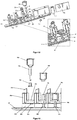
- the dosing system consists of the basic components of a cartridge and a dosing device which can be coupled to the cartridge, which in turn is formed from further components such as component carrier, actuator, closure element, sensor, energy source and / or control unit.
- the metering system according to the invention is mobile. Movable in the sense of this application means that the dosing system is not permanently connected to a dishwasher, but can be removed, for example, from a dishwasher by the user or can be positioned in a dishwasher, ie can be handled independently
- the dosing device for the user is not detachably connected to a dishwasher and only the cartridge is movable.
- the dosing system can be formed from materials which are dimensionally stable up to a temperature of 120.degree.
- the preparations to be dosed may have a pH between 2 and 12, depending on the intended use, all components of the dosing system which come into contact with the preparations should have a corresponding acid and / or alkali resistance. Furthermore, these components should be largely chemically inert by a suitable choice of material, for example against nonionic surfactants, enzymes and / or fragrances.
- a cartridge is understood to mean a packaging material which is suitable for at least one flowable, pourable or spreadable preparation envelop or hold together and which can be coupled for dispensing at least one preparation to a dosing device.
- the cartridge has a preferably rigid chamber for storing a preparation.
- a cartridge can also comprise a plurality of chambers which can be filled with mutually different compositions.
- the cartridge has at least one outlet opening, which is arranged such that a gravity-induced release of preparation from the cartridge in the position of use of the dosing device can be effected.
- conveying means such as e.g. Pumps omitted, whereby the life of a battery or batteries of the dosing device can be increased.
- At least one second chamber is provided for receiving at least one second flowable preparation, the second chamber having at least one outlet opening arranged such that a gravity-induced product release from the second chamber in the use position of the dosing is feasible.
- the arrangement of a second chamber is particularly advantageous if in the separate chambers of the cartridge preparations are stored, which are usually not stable to each other, such as bleaching agents and enzymes.
- one of the chambers can be designed for the delivery of volatile preparations, such as a fragrance to the environment.
- the cartridge is integrally formed.
- the cartridges in particular by suitable blow molding, cost-effectively trained in a manufacturing step.
- the chambers of a cartridge can be separated from one another, for example, by webs or material bridges which are formed during or after the blow molding process.
- the cartridge can also be formed in several pieces by injection molded and then assembled components.
- the cartridge is formed in such a multi-piece, that at least one chamber, preferably all chambers, individually from the metering device can be removed or used in the metering device.
- This makes it possible, with a different consumption of a preparation from a chamber to exchange an already empty chamber, while the rest, which may still be filled with preparation, remain in the metering device.
- a targeted and needs-based refilling the individual chambers or their preparations can be achieved.
- the chamber walls can in particular be shaped such that they can be positively connected to one another.
- the cartridges are shaped in such a way that the chambers can be positively connected to one another only in a specific defined position.
- the chambers of a cartridge can be fixed to one another by suitable connection methods, so that a container unit is formed.
- the chambers can be fixed by a suitable form-fitting, non-positive or cohesive connection releasably or permanently against each other.
- the fixation by one or more of the types of compounds from the group of snap-in compounds, Velcro, press joints, fusions, glued joints, welded joints, solder joints, screw, wedge, clamp or bounce joints can be done.
- the fixation can also be formed by a shrink sleeve (so-called sleeve), which is pulled in a heated state over the entire or sections of the cartridge and firmly encloses the chambers or the cartridge in the cooled state.
- the bottom of the chambers may be funnel-shaped inclined towards the discharge opening.
- the inner wall of a chamber can be formed by suitable choice of material and / or surface design in such a way that a low material adhesion of the preparation to the inner chamber wall is realized. Also by this measure, the residual emptiness of a chamber can be further optimized.
- the cartridge may also be asymmetrical. It is particularly preferred to form the asymmetry of the cartridge in such a way that the cartridge can only be coupled to the dosing device in a predefined position in which an otherwise possible incorrect operation by the user is prevented.
- a metering chamber may be formed in a gravity-induced flow direction of the preparation in front of the outlet opening of a chamber.
- the preparation amount the release of preparation from the chamber to the Environment is to be delivered.
- the closure element of the dosing device which causes the preparation output from a chamber to the environment, can only be put into a dispensing and a closure state without measuring or controlling the dispensing quantity. It is then ensured by the metering chamber that a predefined amount of preparation is released without an immediate feedback of the currently discharged, outflowing preparation amount.
- the metering chambers can be formed in one piece or in several pieces. Furthermore, it is possible to firmly connect the metering chambers with the cartridge or detachably. In a dosing chamber detachably connected to the cartridge, it is possible in a simple manner to connect or exchange dosing chambers with different dosing volumes with a cartridge, whereby a simple adaptation of the dosing volumes to the preparation stored in each chamber and thus a simple assembly the cartridge for different preparations and their dosage is possible.
- one or more chambers in addition to a, preferably bottom-side outlet opening each have a liquid-tight sealable, preferably head-side second chamber opening. Through this chamber opening, it is possible, for example, to refill stored in this chamber preparation.
- ventilation possibilities can be provided in particular in the head region of the cartridge in order to ensure a pressure equalization with decreasing filling level of the chambers between the interior of the cartridge chambers and the environment.
- These ventilation options can be designed, for example, as a valve, in particular silicone valve, micro-openings in a chamber or cartridge wall or the like.
- the cartridge chambers are not ventilated directly but are provided via the metering device or no ventilation, for example when using flexible containers such as bags, this has the advantage that at elevated temperatures during a dishwashing cycle of a dishwasher by the heating of the chamber contents, a pressure is built up, which presses the preparations to be metered in the direction of the outlet openings, so that a good emptying of the cartridge can be achieved. Furthermore, in the case of such an air-free packaging, there is no risk of oxidation of substances of the preparation, which makes bag packaging or else bag-in-bottle packaging appear expedient, in particular for oxidation-sensitive preparations.
- the volume ratio formed from the volume of construction of the metering device and the filling volume of the cartridge ⁇ 1, more preferably ⁇ 0.1, particularly preferably ⁇ 0.05. This ensures that, for a given total construction volume of metering device and cartridge, the overwhelming portion of the construction volume is taken up by the cartridge and the preparation contained therein.
- the cartridge can take on any spatial form. It can for example be cube-shaped, spherical or plate-like.
- the cartridge and the dosing device can in particular be configured with respect to their spatial form such that they ensure the least possible loss of useful volume, in particular in a dishwasher.
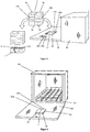
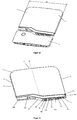
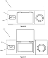
- the dispenser in dishwashers, it is particularly advantageous to mold the device based on dishes to be cleaned in dishwashers. So this example, plate-shaped, be formed in approximately the dimensions of a plate. As a result, the metering device can save space, e.g. be positioned in the lower basket of the dishwasher. Furthermore, the correct positioning of the dosing unit opens up to the user intuitively through the plate-like shape.
- the dosing device and the cartridge preferably have a ratio of height: width: depth of between 5: 5: 1 and 50: 50: 1, particularly preferably of about 10: 10: 1. Due to the "slim" design of the dosing device and the cartridge, it is possible in particular to position the device in the lower cutlery basket of a dishwasher in the receptacles provided for plates. This has the advantage that the dispensed from the dosing preparations go directly into the wash liquor and can not adhere to other items to be washed.
- the metering system is dimensioned in an advantageous embodiment of the invention such that a positioning of the metering only in the appropriate receptacles of the lower basket is enabled.
- the width and the height of the metering system can be selected in particular between 150 mm and 300 mm, particularly preferably between 175 mm and 250 mm.
- the metering unit in cup shape or pot shape with a substantially circular or square base.
- the outlet openings of a cartridge are preferably arranged in a line, whereby a slender, plate-shaped design of the dosing device is made possible.
- the cartridge is advantageous to form the cartridge at least in sections of a transparent material.
- Another way to reduce the effect of heat on a preparation in a chamber of the cartridge is to isolate the chamber by suitable means, e.g. by the use of thermal insulation materials such as styrofoam, which enclose the chamber or the cartridge in a suitable manner, in whole or in part.
- suitable means e.g. by the use of thermal insulation materials such as styrofoam, which enclose the chamber or the cartridge in a suitable manner, in whole or in part.
- Another measure for protecting heat-sensitive substances in a cartridge is, in a plurality of chambers, their arrangement to each other.
- the chamber containing a heat-sensitive product is partially or completely enclosed by at least one further product-filled chamber, which product and chamber functions as thermal insulation for the enclosed chamber in this configuration.
- a first chamber, which contains a heat-sensitive product is partially or completely enclosed by at least one further product-filled chamber, so that the heat-sensitive product in the first chamber has a slower temperature increase when the environment is heated than the one Products in the surrounding chambers.
- the chambers can be arranged around each other according to the matryoshka principle, so that a multilayer insulation layer is formed.
- At least one preparation which is stored in an enclosing chamber, has a thermal conductivity of between 0.01 and 5 W / m * K, preferably between 0.02 and 2 W / m * k, particularly preferably between 0.024 and 1 W / m * K.
- the cartridge is formed in particular dimensionally stable.
- the cartridge is also conceivable to design the cartridge as a flexible packaging such as a tube.
- flexible containers such as bags, especially if they are used according to the "bag-in-bottle" principle in a substantially dimensionally stable receptacle.
- the cartridge has an RFID tag that contains at least information about the contents of the cartridge and that can be read by a sensor unit, which may be provided in particular in the metering device or dishwasher.
- This information can be used, for example, to select a dosing program stored in the dosing unit control unit. In this way it can be ensured that an optimal dosing program is always used for a particular preparation. It can also be provided that in the absence of an RFID tag or an RFID tag with a false or faulty identifier, no metering is done by the metering device and instead an optical or acoustic signal is generated that the user to the present Error indicates.
- the cartridges may also have structural elements which interact with corresponding elements of the metering device according to the key-lock principle, so that, for example, only cartridges of a particular type can be coupled to the metering device. Furthermore, this configuration makes it possible for information about the cartridge coupled to the dosing device to be transmitted to the control unit of the dosing device, as a result of which control of the dosing device coordinated with the contents of the corresponding container can take place.
- the cartridge is designed in particular for receiving flowable cleaning agent. Particularly preferably, such a cartridge has a plurality of chambers for the spatially separated recording in each case of different preparations of a cleaning agent. Exemplary - but not exhaustive - are listed below some possible combinations of filling the chambers with different preparations: Chamber 1 Chamber 2 Chamber 3 Chamber 4 A Alkaline cleaning preparation Enzymatic cleaning preparation - - B Alkaline cleaning preparation Enzymatic cleaning preparation rinse aid - C Alkaline cleaning preparation Enzymatic cleaning preparation rinse aid perfume D Alkaline cleaning preparation Enzymatic cleaning preparation rinse aid disinfecting preparation e Alkaline cleaning preparation Enzymatic cleaning preparation rinse aid pretreatment preparation
- all preparations are flowable, as this ensures rapid dissolution of the preparations in the washing liquor of the dishwasher, whereby these preparations a rapid to immediate cleaning or rinsing, especially on the walls of the washing compartment and / or a Achieve light guide of the cartridge and / or the dosing device.
- the cartridge usually has a total filling volume of ⁇ 5,000 ml, in particular ⁇ 1,000 ml, preferably ⁇ 500 ml, more preferably ⁇ 250 ml, most preferably ⁇ 50 ml.
- the chambers of a cartridge may have the same or different filling volumes.
- the chamber volume ratio is preferably 5: 1, preferably 4: 1: 1 for a three chamber configuration, which configurations are particularly suitable for use in dishwashers.
- the cartridge preferably has three chambers.
- one chamber contains an alkaline cleaning preparation, another chamber an enzymatic preparation and a third chamber a rinse aid, wherein the volume ratio of the chambers is approximately 4: 1: 1.
- the chamber containing the alkaline cleaning preparation preferably has the largest filling volume of the existing chambers.
- the chambers which have a store enzymatic preparation or a rinse aid, in about the same filling volumes.
- a two- and / or three-chamber design of the cartridge is in particular possible to stockpile in particular a perfume, disinfectant and / or Vor harmonyszurung in a detachably arranged on the cartridge or the dosing, another chamber.
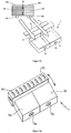
- the cartridge comprises a cartridge bottom, which is directed in the position of use in the direction of gravity down and on which preferably at least one outlet opening arranged in the direction of gravity at the bottom is provided for each chamber.
- the outlet openings arranged on the bottom side are in particular designed such that at least one, preferably all, outlet openings can communicate with the inlet openings of the dosing device, ie preparation via the outlet openings from the cartridge into the dosing device, preferably gravitationally effected, can flow in.
- one or more chambers have a not arranged in the direction of gravity bottom outlet opening. This is particularly advantageous if, for example, a fragrance is to be delivered to the environment of the cartridge.
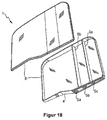
- the cartridge is preferably formed from at least two elements connected to one another in a material-locking manner, wherein the connecting edge of the elements on the cartridge bottom extends outside the outlet openings, that is to say the connecting edge does not intersect the outlet openings.
- the cohesive connection can be produced for example by gluing, welding, soldering, pressing or vulcanization.
- the cartridge elements it is particularly preferable to connect the cartridge elements to one another by means of mirror welding.
- the boundary surfaces are heated by means of a metallic heating mirror, which contains the contour which brings the interfaces into contact, and shortly put into the plastic state, so that after removal of the heating mirror and joining of the parts, these plastic areas solidify again as a melt and solidify Connection result.
- individually molded parts can also be connected to each other by means of laser welding.
- laser welding one of the two materials that are to be melted at the interface must wear an absorbent to absorb the energy content of the laser beam and convert it into heat, which then melts the corresponding material area causes. This is typically accomplished with color pigments that thermally interact with the laser beam conducted into the material. These interfaces to be joined may also be obscured if the material in front of them in the direction of irradiation of the laser beam is transparent to the laser beam and has no absorption property.
- the connecting edge extends along the top, bottom and side surfaces of the cartridge.
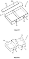
- two cartridge elements can be produced in particular by injection molding, wherein either both elements are trough-shaped or an element trough-shaped and the second element is lid-like.
- At least one of the two cartridge elements can comprise at least one separating web which, in the assembled state of the elements, separates two adjacent chambers of the cartridge from one another.
- a cartridge element to be a cup-shaped container having at least one chamber and the second element to be the cartridge bottom or head connected in a fluid-tight manner to the cup-shaped container along the connecting edge.
- such a further chamber for accommodating a preparation may be arranged on the cartridge and be configured in such a way that a release of volatile substances such as, for example, fragrances from the preparation into the environment of the chamber is effected.
- the outlet openings of the cartridge are closed by closure means at least in the filled, unopened state of the cartridge.
- the closure means may be designed such that they allow a single opening of the outlet opening by destruction of the closure means.
- Such closure means are, for example, sealing foils or caps.
- the outlet openings are each provided with a closure which is in the coupled with a dosing device a state Outflow of preparation from the respective chambers allowed and in the uncoupled state of the cartridge substantially prevents leakage of preparation.
- a closure is designed as a slotted silicone valve.
- the ventilation openings of the cartridge are closed with a closure element before a first coupling with the dosing device.
- the closure element may in particular be a stopper or a cap which, when first coupled with the dosing device, is opened, for example punctured, by the coupling process.
- the cartridge elements forming the cartridge are preferably formed from a plastic and can be formed in a common injection molding process, it may be advantageous to form a hinge acting as a connecting web between the two elements, so that after molding the two elements abut each other by folding and cohesively connected along the connecting edge.
- an energy source in particular a battery or accumulator, is arranged on or in the cartridge, preferably on or in the bottom of the cartridge. Furthermore, means for electrically coupling the energy source with the dosing device can be provided on the cartridge.
- the cartridge comprises at least two chambers, very particularly preferably at least three chambers.
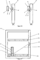
- one ventilation opening and one discharge opening are provided for each chamber.
- the bottom-side ventilation opening is communicatively connected to a ventilation duct whose end facing away from the ventilation opening in the dispensing position of the cartridge coupled to the dosing device opens above the maximum fill level of the cartridge.
- the ventilation duct is completely or partially formed in or on the walls and / or webs of the cartridge.
- the ventilation channel can be integrally formed in or on the walls and / or webs of the cartridge.
- the ventilation duct can advantageously be formed by joining at least two elements forming the cartridge.
- a ventilation duct may be formed by joining a separating web of the cartridge formed in the shell-shaped element with two webs which surround the separating web and are arranged on the cartridge element.
- the ventilation channel is formed by integral joining, in particular by welding, of a separating web of the cartridge formed in the shell-shaped element with two webs which surround the separating web and are arranged on the cartridge element.
- the ventilation duct for example, as so-called. Be formed dip-tube.
- the level level (F) of the cartridge in the unopened, filled state of the cartridge with an inclination of up to 45 ° is not present at the ventilation duct mouth (83).
- the viscosity of a flowable preparation and the ventilation duct are configured in such a way that the preparation is not drawn via capillary forces in the ventilation duct when the preparation at the Vent duct opening is present.
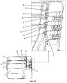
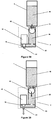
- the coupling of the cartridge with the dosing device is advantageously to be designed such that a dosing device communicating with the inlet opening of the dosing device is arranged on the dosing device, which cooperates with the dockable cartridge or cartridge chamber in such a way that when coupling the ventilation opening of the cartridge or Cartridge chamber with the dosing of the mandrel displaced a volume .DELTA.v in the ventilation duct, whereby a pressure .DELTA.p is generated in the ventilation duct, which is suitable to transport in the ventilation duct, flowable preparation in the connected to the ventilation duct, preparation-storing chamber.
- vent opening of a chamber is communicatively connected to the metering device side mandrel before the closed outlet opening of the corresponding chamber is opened, for example by the communicating connection with the inlet opening of the metering device.
- a ventilation chamber is arranged between the ventilation opening and the ventilation channel.
- the cartridge may be designed such that it can be detachably or firmly arranged in or on the dosing device and / or a dishwasher.
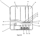
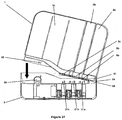
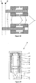
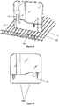
- the dispenser for dispensing at least one flowable detergent preparation inside a household appliance comprises a cartridge coupled to the dispenser wherein the cartridge at least a flowable detergent preparation stored and the cartridge in the direction of gravity bottom side has at least one outlet opening in the with the metering device coupled state is communicatively connected to an inlet opening of the metering device, wherein the metering device and the cartridge have means which cooperate in such a way that a releasable locking between metering device and cartridge can be produced, wherein the metering device and the cartridge in the locked state against each other a pivot point (SP) are pivotable, and that the outlet opening of the cartridge and the inlet opening of the metering console are configured such that they intervene after the production of the latching Cartridge and dosing device are connected communicating by pivoting the cartridge in the coupling state between dosing console and cartridge.
- SP pivot point
- outlet openings of the chambers and the inlet openings of the metering device are arranged and configured such that they are sequentially connected to each other by the pivoting in the latching state in the coupling state of metering device and cartridge.
- means may be provided on the dosing device and / or the cartridge which, in the coupling state of the dosing device and the cartridge, effect a releasable fixing of the cartridge to the dosing device.
- This can be realized, for example, by a collar running on the bottom of the cartridge, which is set back slightly relative to a corresponding dosing device-side collar, so that it is guided on the cartridge-side collar inside the dosing device-side collar.
- the outlet openings of the chambers are arranged one behind the other in the pivoting direction. It is very particularly preferred that the outlet openings of the chambers are arranged in the pivoting direction on a line (L).
- outlet openings of the chambers have approximately the same distance from each other.
- At least two chambers of the cartridge may have different volumes from each other.
- the chamber of the cartridge with the largest volume on the largest distance from the pivot point (SP) of the cartridge 1.
- the ventilation opening of a chamber in the pivoting direction when coupling the cartridge with the dosing device is in each case in front of an outlet opening of the chamber.
- the ratio of depth (T) of the cartridge to width (B) of the cartridge is about 1:20.
- the ratio of height (H) of the cartridge to width (B) of the cartridge is preferably about 1: 1.2.
- the ventilation opening of a chamber in the pivoting direction when coupling the cartridge with the metering device is in each case in front of an outlet opening of the chamber.
- the cartridge for coupling with a dosing device for dispensing at least one cleaning agent preparation from the cartridge into the interior of a household appliance comprises in a preferred embodiment of the invention a light conductor arranged in or on the cartridge, into which a light signal from outside the cartridge can be coupled. It is particularly preferred to couple a light signal that is emitted from the dosing device into the cartridge.
- the light guide may be wholly or partly formed in or on the walls and / or webs of the cartridge.
- the light guide integrally in or on the walls and / or webs of the cartridge.
- the light guide preferably consists of a transparent plastic material. However, it is also possible to form the entire cartridge from a transparent material.
- the light guide is capable of directing light in the visible range (380-780 nm). It is especially preferable that the light guide is suitable for directing light in the near infrared range (780nm-3,000nm). In particular, it is preferred that the light guide is suitable for guiding light in the mid-infrared range (3.0 ⁇ m-50 ⁇ m).
- the light guide consists of a transparent plastic material with a high refractive index.
- the light guide is at least partially completely or partially enclosed by a material having a lower optical refractive index.
- the lower refractive index material may be a preparation stored in a chamber of the cartridge.
- a ratio of the refractive indices of preparation and light guide of 1: 1.10 - 1: 5, preferably, 1: 1.15 - 1: 1.35, particularly preferably 1: 1.15 - 1: 1.20 , where the refractive index was determined in each case at a wavelength of 589 nm.
- the refractive index of the light guide can be determined, for example, according to DIN EN ISO 489.
- the refractive index of the preparation can be determined by means of an Abbe refractometer according to DIN 53491.
- the preparation which completely or partially encloses the light guide has a transmittance of 45% -95%, particularly preferably 60% -90%, very particularly preferably 75% -85%.
- the light guide preferably has a transmittance of> 75%, very particularly preferably> 85%.
- the transmittance can be determined according to DIN5036.
- the wavelength of the light which is transmitted through the optical waveguide corresponds approximately to the wavelength of at least one preparation which at least partially surrounds the optical waveguide, which is not absorbed from the visible spectrum by the preparation. It is particularly preferable here that the wavelength of the light transmitted through the optical fiber and the wavelength not absorbed by the preparation is between 600-800 nm.
- the light signal which can be coupled into the optical waveguide is in particular a carrier of information, in particular, for example, with respect to the operating state of the dosing device and / or the filling level of the cartridge.
- the light guide is designed in such a way that the light signal which can be coupled into the light guide can also be decoupled from the light guide.
- the light guide may be configured in such a way that the light signal can be coupled out at a position of the cartridge which is different from the point in which the light signal can be coupled into the cartridge.
- the coupling or decoupling of the light signal can be realized in particular on a prismatic edge of the cartridge.
- the distance of the light source arranged in the dosing device, in particular an LED, to the point of introduction of the light into the cartridge in the coupling state of the cartridge and dosing device should be kept as low as possible.
- the light signal and the light guide are configured in such a way that a visible to a user light signal to and / or can be generated in the cartridge.
- the light guide can be severed at at least one point in the cartridge in such a way that preparation can fill the separation point.
- a fill level sensor and / or an inclination sensor can be realized in a simple manner, wherein a light signal that passes through the separation point without preparation differs from the light signal that passes through the separation point completely or partially filled with preparation.
- a sensor unit and / or a power source is also arranged on or in the metering device.
- the dosing device consists of a splash-proof housing, that the penetration of water spray, as may occur, for example, when used in a dishwasher, in the interior of the dosing device by at least the control unit, sensor unit and / or actuator are arranged prevented.
- potting materials for example, multicomponent epoxy, and acrylate potting compounds such as methacrylate esters, urethane-metha and cyanoacrylates or two-component materials can be used with polyurethanes, silicones, epoxy resins.
- the material from which the dosing device is formed prevents or at least reduces the growth of a biofilm.
- the material known from the prior art it is possible to use corresponding surface structures of the material known from the prior art, and additives such as biocides.
- the dosing device comprises at least a first interface, which cooperates in or on a household appliance, in particular t a dishwasher formed corresponding interface in such a way that transmission of electrical energy and / or signals from the household appliance to the dosing and / or Dosing to household appliance is realized.
- the interfaces are formed by connectors.
- the interface cells can be designed in such a way that a wireless transmission of electrical energy and / or electrical and / or optical signals is effected.
- the interfaces provided for the transmission of electrical energy are inductive transmitters or receivers of electromagnetic waves.
- the interface of a dishwashing machine can be designed as an alternating current transmitter coil with iron core and the interface of the metering device as a receiver coil with iron core.
- the transmission of electrical energy can also be provided by means of an interface, the household appliance side, an electrically operated light source and dosier confuse wheier yogurt.
- a light sensor such as a photodiode or a solar cell comprises.
- the light emitted by the light source is converted by the light sensor into electrical energy, which in turn feeds, for example, a metering device side accumulator.
- an interface on the dosing device and the water-conducting device for transmitting (ie transmitting and receiving) electromagnetic and / or optical signals, which in particular Radios-, measuring and / or control information of the dosing and / or the water-bearing device such as a dishwasher.
- such an interface can be designed such that a wireless transmission of electrical energy and / or electromagnetic and / or optical signals is effected.
- At least one interface is configured to emit and / or receive optical signals in the wavelength range between 600-800nm. Since darkness usually prevails in the interior of the dishwasher during operation of a dishwasher, signals in the visible, optical region, for example in the form of signal pulses or light flashes, can be emitted and / or detected by the dosing device. It has proven particularly advantageous to use wavelengths between 600-800 nm in the visible spectrum.
- the interface comprises at least one LED.
- the interface comprises at least two LEDs. It is also possible according to a further preferred embodiment of the invention to provide at least two LEDs which emit light in a mutually different wavelength. This makes it possible, for example, to define different signal bands on which information can be sent or received.
- At least one LED is an RGB LED whose wavelength is adjustable.
- an LED can be used to define different signal bands that emit signals at different wavelengths.
- light is emitted at a different wavelength during the drying process, during which there is a high level of atmospheric humidity (mist) in the washing compartment, than, for example, during a washing step.
- the interface of the dosing device can be configured such that the LED is provided both for emitting signals inside the dishwasher, in particular when the dishwasher door is closed, and also for visually displaying an operating state of the dosing device, in particular when the dishwasher door is open.
- an optical signal is designed as a signal pulse with a pulse duration between 1 ms and 10 seconds, preferably between 5 ms and 100 ms seconds.
- the interface of the dosing device is configured such that it emits an optical signal with the dishwasher closed and unloaded, that a mean illuminance E between 0.01 and 100 lux, preferably between 0.1 and 50 lux measured on the causes the Spülraum limiting walls.
- This illuminance is then sufficient to cause multiple reflections with or on the other Spipporaumassin and so possible signal shadows in the washing compartment, in particular in the loading condition of the dishwasher to reduce or prevent.
- the signal transmitted and / or received by the interface is in particular a carrier of information, in particular a control signal or a signal representing an operating state of the dosing device and / or the dishwasher.
- the dosing device for dispensing at least one washing and / or cleaning agent preparation from a cartridge into the interior of a domestic appliance has a light source, by means of which a light signal can be coupled into a light guide of the cartridge.
- the light source may be an LED.
- the corresponding light signals can for example be slid into the head of the cartridge, so that even if the dosing is positioned in the plate receptacle between other items to be washed, the light signals are visually perceptible by the user with proper loading of the dish drawer of the head-side portion of the dishes and the cartridge usually remains uncovered.
- the light signal coupled into the optical waveguide of the cartridge and passing through the optical waveguide to be detectable by a sensor located on the dosing device. This will be explained in more detail in a subsequent section.
- the dosing device for dispensing at least one washing and / or cleaning agent preparation inside a household appliance comprises at least one optical transmitting unit, wherein the optical transmitting unit is configured in such a way that signals from the transmitting unit in a coupled with the dosing device Cartridge can be coupled and signals from the transmitting unit in the environment of the dosing device are radiated.
- the optical transmitting unit is configured in such a way that signals from the transmitting unit in a coupled with the dosing device Cartridge can be coupled and signals from the transmitting unit in the environment of the dosing device are radiated.
- the optical transmitting unit may be an LED, which preferably emits light in the visible and / or IR range. It is also conceivable to use another suitable optical transmitting unit, e.g. a laser diode, to use. It is necessary to use an optical transmitter which emits light in the wavelength range between 600-800nm.
- the dosing device may comprise at least one optical receiving unit.
- the dosing device can receive signals from an optical transmission unit arranged in the household appliance.
- This can be realized by any suitable optical receiving unit, such as photocells, photomultipliers, semiconductor detectors, photodiodes, photoresistors, solar cells, phototransistors, CCD and / or CMOS image sensors.
- the optical receiver unit is suitable to receive light in the wavelength range of 600-800nm.
- the optical receiving unit on the dosing device can also be configured such that the signals that can be coupled from the transmitting unit into a cartridge coupled to the dosing device can be decoupled from the cartridge and detected by the optical receiving unit of the dosing device.
- the signals emitted by the transmitting unit into the surroundings of the metering device may preferably represent information regarding operating conditions or control commands.
- the metering device for dispensing at least one flowable detergent and / or cleaning agent preparation into the interior of a domestic appliance may in particular have a metering chamber communicating with the metering device communicating cartridge connected to a metering device in the metering chamber inlet, so that in the position of use of the metering preparation gravitational effects the cartridge is inserted into the metering chamber with a Dosierhuntauslass downstream of the Dosierhunteinlass which can be closed by a valve in the metering a float is arranged whose density is less than the density of the preparation, wherein the float is formed in the manner in that the preparation can circumnavigate and / or flow through the floating body and the floating body and the metering chamber inlet are configured in such a way that the metering chamber inlet can be closed by the floating body.
- the float can the Dosierhunteinlass sealing or not sealing.
- a non-sealing closure of the float is indeed at the Dosierhunteinlass, but this seals not against inflow of preparation from the cartridge, so that an exchange of preparation between the cartridge and the metering chamber is possible.
- the float body acts in this embodiment of the invention as a targeted throttle, which minimizes the slippage between the metering chamber inlet and the metering chamber outlet when opening the valve and thus determines the metering accuracy.
- the float and the metering chamber can be designed as a self-closing valve, on the one hand, in order to bring about the lowest possible energy consumption in an energy self-sufficient dosing device; on the other hand, a defined amount of preparation, which corresponds approximately to the filling volume of the dosing, released.
- the density of the detergent and / or cleaning agent preparation and the density of the floating body such that the floating body has a rate of rise of 1.5 mm / sec to 25 mm / sec, preferably 2 mm / sec to 20 mm / sec, in particular preferably 2.5 mm / sec to 17.5 mm / sec in the washing and / or cleaning agent preparation. This ensures a sufficiently rapid closing of the metering chamber inlet by the ascending float and thus a sufficiently short interval between two preparation dosages.
- the rate of climb of the floating body can advantageously also be stored in the control unit of the dosing device which activates the valve. This makes it possible to connect the valve so that a release of preparation is greater than the volume of the metering realized. In this case, the valve is then reopened before the float reaches its upper closure position at Dosierhunteinlass and closes the Dosierhunteinlass.
- the floating body and the metering chamber are configured such that in the delivery position of the valve associated with the metering chamber outlet, the rate of rise of the floating body in the washing and / or detergent preparation is smaller than the flow rate of the preparation surrounding the float from the metering chamber.
- the float is preferred to form substantially spherical.
- the float may also be substantially cylindrical.
- the metering chamber is substantially cylindrical. Furthermore, it is advantageous that the diameter of the metering chamber is slightly larger as the diameter of the cylindrical or spherical floating body, so that a slip between the metering chamber and floating body arises with respect to the preparation.
- the float is made of a foamed, polymeric material - in particular of foamed PP - formed.
- the metering chamber is L-shaped.
- a diaphragm between the Dosierhunteinlass and Dosierhuntauslass be arranged, wherein the aperture is formed such that it is sealingly or non-sealingly closed by the float, the float is preferably disposed between the aperture and the Dosierhunteinlass.
- the dosing device comprises a component carrier on which at least the actuator and the closure element and the energy source and / or the control unit and / or the sensor unit and / or the dosing chamber are arranged.
- the component carrier has receptacles for the said components and / or the components are formed integrally with the component carrier.
- the receptacles for the components in the component carrier can be provided for a positive, positive and / or cohesive connection between a corresponding component and the corresponding receptacle.
- the energy source, the control unit and the sensor unit are arranged in a module on or in the component carrier.
- the energy source, the control unit and the sensor unit are combined in an assembly. This can be realized, for example, in that the energy source, the control unit and the sensor unit are arranged on a common electrical printed circuit board.
- the component carrier is designed trough-like, manufactured as an injection molded part. It is particularly preferred that the metering chamber is formed integrally with the component carrier.
- the component carrier By the component carrier a largely simple automatic assembly with the necessary components of the dosing device is possible.
- the component carrier can be prefabricated as a whole, preferably automatically and assembled to form a dosing device.
- the trough-like component carrier can be closed in accordance with an embodiment of the invention after the assembly liquid-tight of a, for example, cover-like closure element.
- the closure element may be formed, for example, as a film which is liquid-tight, materially connected to the component carrier and forms one or more liquid-tight chambers with the trough-like component carrier.
- the closure element can also be a console, in which the component carrier can be inserted, wherein the console and the component carrier in the assembled state form the dosing device.
- the component carrier and the console in the assembled state cooperate in such a way that between the component carrier and the console, a liquid-tight connection is formed, so that no rinse water can get into the interior of the dosing device or the component carrier.
- the receptacle for the actuator on the component carrier in the direction of gravity is arranged above the metering chamber, whereby a compact design of the metering device can be realized.
- the compact design can be further optimized by the Dosierhunteinlass is arranged on the component carrier above the receptacle of the actuator in the position of use of the dosing device.
- the components it is also preferable for the components to be arranged on the component carrier substantially in a row relative to one another, in particular along the longitudinal axis of the component carrier.
- the receptacle for the actuator has an opening which is in line with the Dosierhuntauslass so that a closure element from the actuator through the opening and the Dosierhuntauslass can be moved back and forth.
- the component carrier is formed of a transparent material.
- the component carrier comprises at least one optical waveguide, via which light from the environment of the dosing device can be directed to an optical transmitting and / or receiving unit into and / or out of the interior (s) of the dosing device or the component carrier, the optical waveguide in particular is formed integrally with the transparent component carrier.
- At least one opening is provided in the dosing device, by means of which light from the environment of the dosing device in and / or out of the optical waveguide can be coupled in and / or out.
- an actuator is a device which converts an input variable into a different output quantity and with which an object is moved or whose movement is generated, wherein the actuator is coupled to at least one shutter element, directly or indirectly releasing the preparation at least one cartridge chamber can be effected.
- the actuator may be driven by drives selected from the group of gravity drives, ion drives, electric drives, motor drives, hydraulic drives, pneumatic drives, gear drives, threaded spindle drives, ball screws, linear drives, roller screws, tooth worm drives, piezoelectric actuators, chain drives, and / or recoil drives.
- drives selected from the group of gravity drives, ion drives, electric drives, motor drives, hydraulic drives, pneumatic drives, gear drives, threaded spindle drives, ball screws, linear drives, roller screws, tooth worm drives, piezoelectric actuators, chain drives, and / or recoil drives.
- the actuator may be formed of an electric motor coupled to a transmission that converts the rotational movement of the motor into a linear motion of a carriage coupled to the transmission. This is particularly advantageous for a slim, plate-shaped design of the dosing unit.
- At least one magnetic element can be arranged on the actuator, which causes a product discharge from the container with a magnet element with the same polarity on a dispenser as soon as the two magnetic elements are positioned against one another such that magnetic repulsion of the homopolar magnetic elements is effected and a non-contact release mechanism is realized.
- the actuator is a bistable solenoid, which forms a pulse-controlled, bi-stable valve together with an engaging in the bistable solenoid, designed as a plunger core closure element.
- Bistable lifting magnets are electromechanical magnets with linear direction of movement, wherein the plunger locked in each end position without current.
- Bistable lifting magnets or valves are known in the art.
- a bistable valve requires a pulse to change valve positions (open / closed) and then remains in that position until a counter pulse is sent to the valve. Therefore, one speaks of a pulse-controlled valve.
- a significant advantage of such pulse-controlled valves is that they do not consume energy to dwell in the Ventilendlagen, the closed position and discharge position, but only need an energy pulse to change the valve layers, thus the Ventilendlagen are considered to be stable.
- a bistable valve remains in that switching position, which last received a control signal.
- the closure element By means of a current pulse, the closure element (plunger core) is moved to an end position. The power is switched off, the closing element holds the position. By current pulse, the closure element is moved to the other end position. The power is switched off, the closing element holds the position.
- a bistable property of solenoids can be realized in different ways.
- a division of the coil is known.
- the coil is split more or less centrally so that a gap is created.
- a permanent magnet is used.
- the plunger core itself is both the front and the back so turned off that he has in the respective end position a flat surface lying to the frame of the magnet.
- the magnetic field of the permanent magnet flows over this surface.
- the diving core sticks here.
- the use of two separate coils is possible.
- the principle is similar to the bistable solenoid with split coil. The difference is that they are actually two electrically different coils. These are controlled separately, depending on the direction in which the plunger is to be moved.
- the closure element is coupled to the actuator in such a way that the closure element from the actuator in a closed position and in a passage position (dispensing position) is displaceable, wherein the closure element is designed as open / close valve element, that the actuator is designed such that it controlled by a suitable pulse selectively determinable occupies one of two end positions and without activation, the reached end position stably maintained, and thus that the combination forms a pulse-controlled, bistable open / close valve.
- the actuator may for this purpose be designed as a bistable solenoid with an armature receiving space and a surrounding outer receiving space.
- the armature of the bistable solenoid may be configured to form or couple to the closure element.
- the armature receiving space of the actuator from the outer receiving space of the actuator may be liquid-tight and preferably also gas-tight.
- At least the outer surface of the armature from a material which can not be attacked by the washing or cleaning agent to be metered, in particular from a plastic material.
- the armature preferably comprises a core of a magnetizable, in particular a ferromagnetic material and a permanent magnet positioned in the outer receiving space, wherein a coil is arranged at each of its two axial ends.
- permanent magnets are arranged axially antipolig and that in the outer receiving space at both axial ends yoke rings of a ferromagnetic material, in particular iron, and between these a coil winding are arranged.
- the axial distance of the yoke rings is greater than the axial distance of the permanent magnets.
- Further yoke rings can be arranged in the armature at its axial ends, wherein in the outer receiving space at both axial ends of permanent magnets are arranged axially antipolig and between these a coil winding is arranged.
- the axial distance of the permanent magnets is in this case preferably greater than the axial distance of the yoke rings.
- the one actuator / closure element combination is provided in a metering device of a metering system with a cartridge for flowable washing or cleaning agent having a plurality of chambers for spatially separated receiving each different preparations of a detergent or cleaning agent and with a detachable with the cartridge
- the dosing device comprises: a power source, a control unit, a sensor unit, an actuator, which is so connected to the power source and the control unit, that a control signal of the control unit causes an actuation of the actuator, a closure element, with the actuator in the Art is coupled so that it is displaceable by the actuator in a Verschetz ein and in a passage position (dispensing position), at least one metering chamber communicating communicates with at least one of the cartridge chambers of the cartridge in a combined with a cartridge dosing en, wherein the metering chamber has an inlet for the inflow of detergent or cleaning agent from a Cartridge chamber and an outlet for the discharge of detergent or cleaning agent from the meter
- the actuator is arranged in a component carrier in the manner that in the use position of the metering device, a receptacle for the actuator on the component carrier in the direction of gravity above the metering chamber is arranged.
- the inlet of the dosing chamber is arranged on the component carrier above the receptacle of the actuator.
- the metering device has a component carrier in which a receptacle for the actuator on the component carrier is arranged laterally next to the metering chamber in the use position of the metering device.
- the receptacle for the actuator preferably has an opening which is in line with the outlet of the metering chamber, wherein the closure element from the actuator through the opening to the outlet is movable back and forth.
- a closure element is a component that acts on the actuator and that as a result of this action causes the opening or the closure of an outlet opening.
- the closure element can be valves which can be brought into a product delivery position or closure position by the actuator.
- the embodiment of the closure element and the actuator in the form of a solenoid valve, wherein the dispenser are configured by the valve and the actuator by the electromagnetic or piezoelectric drive of the solenoid valve.
- the amount and timing of the dosage can be controlled very accurately by the use of solenoid valves.
- a sensor is a measuring sensor or measuring sensor which can quantitatively record certain physical or chemical properties and / or the material quality of its environment qualitatively or as a measured variable.
- the dosing unit preferably has at least one sensor which is suitable for detecting a temperature.
- the temperature sensor is designed in particular for detecting a water temperature.
- the dosing unit comprises a sensor for detecting the conductivity, whereby in particular the presence of water or the spraying of water, in particular in a dishwasher, is detected.
- the dosing unit has a sensor which can determine physical, chemical and / or mechanical parameters from the surroundings of the dosing unit.
- the sensor unit may comprise one or more active and / or passive sensors for the qualitative and / or quantitative detection of mechanical, electrical, physical and / or chemical variables, which are passed as control signals to the control unit.
- the sensors of the sensor unit from the group of timers, temperature sensors, infrared sensors, brightness sensors, temperature sensors, motion sensors, strain sensors, speed sensors, proximity sensors, flow sensors, color sensors, gas sensors, vibration sensors, pressure sensors, conductivity sensors, turbidity sensors, Schall Bateldrucksensoren, "Lab-on-a Chip sensors, force sensors, acceleration sensors, inclination sensors, pH sensors, humidity sensors, magnetic field sensors, RFID sensors, magnetic field sensors, Hall sensors, biochips, odor sensors, hydrogen sulfide sensors and / or MEMS sensors.
- Suitable flow sensors may be selected from the group of orifice flow rate sensors, electromagnetic flowmeters, Coriolis mass flow rate measurement, vortex flowmeter, ultrasonic flow rate measurement, variable area flow measurement, annular piston flow measurement, thermal mass flow measurement, or differential pressure flow measurement.
- At least two sensor units are provided for measuring mutually different parameters, with very particular preference a sensor unit is a conductivity sensor and a further sensor unit is a temperature sensor. Furthermore, it is preferred that at least one sensor unit is a brightness sensor.
- the sensors are especially adapted to detect the beginning, the course and the end of a washing program.
- the sensor combinations listed in the following table can be used Sensor 1 Sensor 2 Sensor 3 Sensor 4 conductivity sensor temperature sensor conductivity sensor temperature sensor brightness sensor conductivity sensor temperature sensor brightness sensor turbidity sensor sound sensor temperature sensor
- the conductivity sensor can be detected, for example, whether the conductivity sensor is wetted by water, so that, for example. determine if there is water in the dishwasher.
- Rinsing programs usually have a characteristic temperature profile, the u.a. is determined by the heating of the rinse water and the drying of the dishes, which can be detected by a temperature sensor.
- the light penetration into the interior of a dishwasher can be detected when the dishwasher door is opened, resulting in e.g. indicates an end to the washing program.
- a turbidity sensor can also be provided. From this it is also possible, for example, to select a dosing program in the dosing device that applies to the determined contamination situation.
- a temperature-dependent viscosity curve of at least one preparation to be stored in the control unit, wherein the dosage is adjusted according to the temperature and thus the viscosity of the preparation by the control unit.
- an apparatus for direct determination of the viscosity of the preparation is provided.
- the data line between the sensor and the control unit can be realized via an electrically conductive cable or wirelessly.
- at least one sensor outside the dosing device is positioned or positionable in the interior of a dishwasher and a data line - in particular wireless - for transmitting the measured data from the sensor to the dosing device is formed.
- a wirelessly formed data line is formed in particular by the transmission of electromagnetic waves or light. It is preferable to form a wireless data line according to standardized standards such as Bluetooth, IrDA, IEEE 802, GSM, UMTS, etc.
- At least one sensor unit is arranged on or in the control unit.
- the sensor unit is arranged at the bottom of the dosing device, wherein in the position of use the bottom of the dosing device is directed downward in the direction of gravity.
- the sensor unit comprises a temperature and / or a conductivity sensor.
- the energy consumers of the dosing device in particular the control unit, including an on / off switch can be connected to the power source and the energy source only after reaching the On-state of the on / off switch loaded with a sensor unit forms the on / off switch or is connected to this and switches.
- the sensor unit prefferably has two contacts in contact with the environment at the bottom of the dosing device, in particular configured as contact pins projecting downwards from the bottom, one contact as anode contact and the other contact as cathode contact the power source is connected and that without electrically conductive connection between the contacts of the off-state located on / off switch remains in the off state and upon the emergence of an electrically conductive connection between the contacts of the off-state on / off Switch in the on state switches.
- the on / off switch is provided or combined with a self-holding circuit which ensures latching of the energy supply of the energy consumers after reaching the on state of the on / off switch up to a switch-off signal of the control unit . causes.
- the on / off switch can be designed in particular as a transistor circuit. It is preferable that the transistor of the on / off switch designed as a pnp transistor and the emitter, possibly via a drive circuit, to the supply voltage to the collector, possibly via a drive circuit to ground and to the cathode contact and the base on the one hand, possibly via a drive circuit, to the supply voltage, on the other hand, if necessary via a drive circuit to the anode contact, is connected.
- the drive circuit preferably has at least one drive resistor, which is designed in particular as a resistance voltage divider.
- a sensor unit designed as a conductivity sensor which has two contacts in contact with the environment at the bottom of the dosing device and the anode contact of the on / off Sensor unit is simultaneously the anode contact of the conductivity sensor forming sensor unit.
- the sensor unit forming the temperature sensor may be integrated in a contact, in particular the cathode contact, of the sensor unit forming the conductivity sensor.
- the contact of the sensor unit forming the conductivity sensor, which receives the temperature sensor may preferably be designed as a hollow contact pin, in which the temperature sensor of the sensor unit forming the temperature sensor is arranged.
- the energy source, the control unit and the sensor unit are combined in an assembly on or in the component carrier.
- the contacts of a conductivity sensor arranged on the bottom side are surrounded by an electrically conductive silicone.
- the conductivity sensor may in this case be designed, in particular in the form of a resistance measurement, between two contacts spaced apart from one another and in contact with the surroundings of the dosing device.
- the silicone is flush-mounted in the bottom of the metering device.
- the silicone has an approximately circular base. The silicone shows a good wettability with water and thus provides good measurement results regarding the detection of water in the dishwasher.
- a control unit in the sense of this application is a device which is suitable for influencing the transport of material, energy and / or information.
- the control unit influences actuators with the aid of information, in particular of measuring signals of the sensor unit, which processes them in the sense of the control target.
- control unit may be a programmable microprocessor.
- a plurality of dosing programs is stored on the microprocessor, which are selectable and executable in a particularly preferred embodiment according to the container coupled to the dosing device.
- the control unit has, in a preferred embodiment, no connection to the possibly existing control of the household appliance. There will be no Information, in particular electrical, optical or electromagnetic signals, exchanged directly between the control unit and the control of the household appliance.
- control unit is coupled to the existing control of the household appliance.
- this coupling is wireless.
- a transmitter on or in a dishwasher preferably on or at the dosing chamber embedded in the door of the dishwasher, which wirelessly transmits a signal to the dosing unit when the control of the domestic appliance controls the dosing of, for example, a detergent from the dosing unit Dosing or rinse aid causes.
- the control unit can store several programs for releasing different preparations or releasing products in different applications.
- the call of the corresponding program can be effected by means of corresponding RFID labels or geometric information carriers formed on the container.
- the same control unit for a plurality of applications, for example for metering detergent in dishwashers, for dispensing perfumes in room fragrancing, for applying cleaning substances to a toilet bowl, etc.
- control unit can be configured in such a way that on the one hand the dosing takes place in a sufficiently short time to ensure a good cleaning result and on the other hand the dosing of the preparation does not occur so quickly.
- This can be realized, for example, by an interval-like release, whereby the individual metering intervals are set in such a way that the corresponding metered amount dissolves completely during a cleaning cycle.
- the metering intervals for dispensing a preparation are between 30-90 seconds, particularly preferably 45-75 seconds.
- the delivery of preparations from the dosing device can be done sequentially or simultaneously.
- the dishwasher and the dosing device work together in such a way that 1 mg to 1 g of surfactant are released in the final rinse program of the dishwasher per m 2 Spülraumwyer Structure. This ensures that the walls of the washing compartment retain their gloss even after a plurality of rinsing cycles and the dosing system retains its optical transmission capability.
- the dishwasher and the dosing device to interact in such a way that at least one enzyme-containing preparation and / or alkaline preparation is released in the pre-washing program and / or main washing program, with the release of the enzyme-containing preparation preferably taking place prior to release the alkaline preparation takes place.
- the dishwasher and the dosing device work together in such a way that 0.1 mg-250 mg of enzyme protein are released in the pre-washing program and / or main wash program of the dishwasher per m 2 of dishwashing area, whereby the gloss level of the dishwashing walls is further improved or improved It is also retained after a large number of rinsing cycles.
- data such as control and / or dosing programs of the control unit or stored by the control unit
- Operating parameters or protocols are read from the control unit or loaded into the control unit.
- This can be realized, for example, by means of the optical interface, wherein the optical interface is correspondingly connected to the control unit.
- the data to be transmitted are then encoded as light signals, in the wavelength range between 600-800nm, and transmitted or received.
- a present in the metering sensor for transmitting data from and / or to the control unit.
- the contacts of a conductivity sensor which are connected to the control unit and which provides a conductivity determination by means of a resistance measurement at the contacts of the conductivity sensor, can be used for data transmission.
- a method for operating a dosing device not connected to a household appliance for dispensing at least one detergent and / or detergent preparation inside the household appliance may be formed, wherein at least one dosing program is stored in the control unit, and the control unit is at least an actuator located in the metering device cooperates in such a way that washing and / or cleaning agent preparation is releasable from the metering device inside the household appliance, the metering device comprises at least one receiving unit for signals emitted by at least one arranged in the household appliance transmitting unit and at least a part the signals in the dosing device-side control unit are converted into control commands for the actuators of the dosing device, the reception of the signals being monitored on the dosing device side by means of the control unit and not receiving the signals on the dosing a dosing from the control unit of the dosing device is activated.
- the household appliance-side signal is emitted in predefined, periodic time intervals from the household appliance-side transmitting unit into the interior of the household appliance.
- the defined periodic intervals in which a signal is emitted from the household appliance-side transmitting unit are stored in the control unit of the metering device and in the household appliance. If the contact between the transmitting unit of the domestic appliance breaks down after receiving a signal at the dosing device, this demolition can be determined by comparing the time elapsed since the last received signal and the time in which periodic time interval, the reception of a subsequent signal is expected to be determined Dosierettifact.
- the periodic signal intervals are selected between 1 second and 10 minutes, preferably between 5 seconds and 7 minutes, more preferably between 10 seconds and 5 minutes. It is particularly preferred that the periodic signal intervals are selected between 3 minutes and 5 minutes.
- control unit of the dosing device after the expiration of a predefined time interval t 1-2 starting at t 1 in which no further appliance signal is received by the dosing device, activates a dosing program from the control unit of the dosing device.
- the control unit evaluates the number and / or time sequence of the signals received by the dosing device in such a way that a dosing program is activated in the control unit in accordance with the evaluation result.
- This makes it possible to determine, for example, the duration of a washing program in a dishwasher since its start by comparing the time of the first signal reception to the time of determining the signal break, so that according to the progress of the washing program, a suitable, the progress of the wash program corresponding dosing in the control unit of the dosing device is activated.
- a dosing program stored in the control unit of the dosing device is activated in the control unit starting from a defined program step corresponding to the progress of the washing program.
- a dosing program in the dosing device during a signal rupture in the main rinse cycle of a rinse program, which is provided for a main rinse cycle and subsequent rinse program sections.
- the signals transmitted by the household appliance-side transmitting unit comprise at least one control signal.
- the signals emitted by the household appliance-side transmitting unit comprise at least one monitoring signal.
- At least one dosing program stored in the control unit comprises a dosing program of the household appliance. This makes it possible that in a signal separation between the household appliance and the dosing unit, the dosing continues a dosing program started by the household appliance.
- the metering programs stored in the control unit of the metering device include the metering programs of the household appliance.
- the transmission of a monitoring signal and / or control signal to the household appliance can be effected manually by a user.
- a user can check, for example, whether there is a signal reception between the transmitting unit of the household appliance and the dosing device in one of his chosen positioning of the dosing within the household appliance.
- This can be realized, for example, by an operating element embodied on the household appliance, such as a pushbutton or switch, which transmits a monitoring and / or control signal when actuated.
- the energy source a component of the dosing, which is expedient to provide a suitable for the operation of the dosing or the dosing energy.
- the energy source is designed such that the dosing system is self-sufficient.
- the energy source provides electrical energy.
- the energy source may be, for example, a battery, an accumulator, a power supply, solar cells or the like.
- a battery may be selected from the group of alkaline manganese batteries, zinc-carbon batteries, nickel-oxyhydroxide batteries, lithium batteries, lithium iron sulfide batteries, Zinc air batteries, zinc chloride batteries, mercury oxide zinc batteries and / or silver oxide zinc batteries.
- Lead accumulators lead dioxide / lead
- nickel-cadmium batteries nickel-metal hydride batteries
- lithium-ion batteries lithium-polymer batteries
- alkaline manganese batteries silver-zinc batteries
- nickel batteries etc.
- Hydrogen batteries zinc bromine batteries, sodium nickel chloride batteries and / or nickel-iron batteries.
- the accumulator can in particular be designed in such a way that it can be recharged by induction.
- mechanical energy sources consisting of one or more coil spring, torsion spring or torsion bar spring, spiral spring, air spring / gas spring and / or elastomer spring.
- the energy source is dimensioned such that the dosing device can go through about 300 dosing cycles before the energy source is exhausted. It is particularly preferred that the energy source can run between 1 and 300 dosing cycles, most preferably between 10 and 300, more preferably between 100 and 300, before the energy source is depleted.
- means for energy conversion can be provided in or on the dosing unit, which generate a voltage by means of which the accumulator is charged.
- these means may be designed as a dynamo, which is driven by the water flows during a rinse cycle in a dishwasher and emits the voltage thus generated to the accumulator.
- an optical transmitting and / or receiving unit is arranged within the dosing device, in particular in or on the component carrier, in order to protect the electrical and / or optical components of the transmitting and / or receiving unit from spray and rinse water.
- a light guide is disposed between the optical transmitting and / or receiving unit and the environment of the dosing, which identifies at least a light transmission of 75%.
- the light guide preferably consists of a transparent plastic with a light transmittance of at least 75%.
- the transmittance of the optical fiber is defined as the transmittance between the surface of the optical fiber at which the light from the environment of the metering device in the Light guide is coupled and the surface at which the light is coupled out of the optical fiber to the optical transmitting and / or receiving unit.
- the transmittance can be determined according to DIN5036.
- the optical waveguide comprises at least one input and / or decoupling point to which light is coupled or decoupled from an optical transmitting and / or receiving unit and / or from the environment of the dosing device.
- the light guide is formed integrally with the component carrier.
- the component carrier is therefore formed of a transparent material.
- an opening is provided in the dosing device.
- the input and / or decoupling point can be arranged in the lateral surface in the bottom or head of the dosing device.
- the light guide can also be constructed in multiple layers and / or in multiple pieces of the same or different materials. It is also possible to provide an air gap between a multi-layered and / or multi-piece molded optical fiber.
- the transmittance of the light guide is understood in a multi-layered and / or multi-piece structure between the surface of the light guide at which the light from the environment of the dosing device is coupled into the light guide and the surface at which the light from the optical fiber to optical transmission and / or receiving unit is decoupled.
- At least two input or extraction points of the light guide are provided with the environment. It is particularly advantageous that the input or extraction points on the dosing device are substantially opposite.
- the dosing system has at least one vibrating atomizer, via which it is possible to transfer a preparation into the gas phase or to keep it in the gas phase.
- the vibrating atomizer via which it is possible to transfer a preparation into the gas phase or to keep it in the gas phase.
- This embodiment is particularly advantageous when used in a dishwashing machine, where a corresponding release of preparation into the gas phase takes place in a closable washing compartment.
- the preparation introduced into the gas phase can be distributed evenly in the washing compartment and deposited on the items to be washed in the dishwasher.
- the preparation released by the vibrating atomizer may be selected from the group of surfactant-containing preparations, enzyme-containing preparations, odor-neutralizing preparations, biocidal preparations, antibacterial preparations.
- the cleaning preparations By applying the cleaning preparations to the washware from the gas phase, a uniform layer of the corresponding cleaning preparation is applied to the washware surface. It is particularly preferred that the entire Spülgutober Design is wetted by the cleaning preparation.
- a preparation by means of the vibrating atomizer on the dishes after the completion of a cleaning program of a dishwasher.
- This may be, for example, an antibacterial preparation or a preparation for the modification of surfaces.
- the metering system according to the invention comprises at least one first aqueous surfactant-containing preparation which in particular has a pH of less than 5.5, preferably less than 4, particularly preferably less than 3.5 (10% solution, 20 ° C.).
- the acidic adjustment of the surfactant phase in particular limescale deposits on the walls of the washing compartment can be prevented, which can reduce the gloss and the reflectivity of the walls.
- it has surprisingly been found that by means of such a surfactant preparation the transmittance of the light guide between the optical transmission and / or receiving unit of the dosing device and the environment of the dosing device can be kept constant over a plurality of rinsing cycles.
- the securing and improvement of a wireless signal transmission for controlling the dosing systems positioned in the washing compartment is ensured according to the invention by means of a specific surfactant-containing preparation to be released in the rinse cycle.
- this preparation is distinguished in particular by its pH below 5.5 (10% solution, 20 ° C.).
- the preparations according to the invention contain acidifying agents.
- the proportion by weight of the acid (s) in the total weight of the preparation according to the invention based on the total weight of the preparation, preferably between 0.05 and 10 wt .-%, preferably between 0.1 and 8 wt .-% and in particular between 0.2 and 5% by weight.
- Suitable acidifying agents are both inorganic acids and organic acids, with particular preference given to organic acids in the context of the present application for reasons of consumer protection and handling safety.
- Particularly preferred organic acids are the mono-, oligo- and polycarboxylic acids, in particular citric acid, acetic acid, tartaric acid, succinic acid, glutaric acid, malonic acid, adipic acid, maleic acid, fumaric acid, oxalic acid and the homo- or copolymeric polycarboxylic acids.
- Organic sulfonic acids such as amidosulfonic acids are also usable.
- Particularly preferred preparations according to the invention contain, based on their total weight, between 0.05 and 10% by weight, preferably between 0.1 and 8% by weight and in particular between 0.2 and 5% by weight of acetic acid and / or citric acid.
- preparations according to the invention may also contain salts of the abovementioned acids as buffer substances.
- Preference is given here to the alkali metal salts and among these in turn the sodium or potassium salts.
- the surfactants form a second essential constituent of preparations according to the invention.
- the group of surfactants also includes, in particular, the nonionic surfactants used with particular preference.
- nonionic surfactants known to the person skilled in the art can be used as nonionic surfactants.
- Suitable nonionic surfactants are, for example, alkyl glycosides of the general formula RO (G) x , in which R is a primary straight-chain or methyl-branched, in particular in the 2-position methyl-branched aliphatic radical having 8 to 22, preferably 12 to 18 carbon atoms and G is the symbol which represents a glycose unit having 5 or 6 C atoms, preferably glucose.
- the degree of oligomerization x which indicates the distribution of monoglycosides and oligoglycosides, is any number between 1 and 10; preferably x is 1.2 to 1.4.
- Nonionic surfactants of the amine oxide type for example N-cocoalkyl-N, N-dimethylamine oxide and N-tallowalkyl-N, N-dihydroxyethylamine oxide, and the fatty acid alkanolamides may also be suitable.
- the amount of these nonionic surfactants is preferably not more than that of the ethoxylated fatty alcohols, especially not more than half thereof.
- nonionic surfactants used either as the sole nonionic surfactant or in combination with other nonionic surfactants are alkoxylated, preferably ethoxylated or ethoxylated and propoxylated fatty acid alkyl esters, preferably having from 1 to 4 carbon atoms in the alkyl chain.
- washing or cleaning agents in particular automatic dishwashing detergents, contain nonionic surfactants from the group of the alkoxylated alcohols.
- the nonionic surfactants used are preferably alkoxylated, advantageously ethoxylated, in particular primary, alcohols having preferably 8 to 18 carbon atoms and on average 1 to 12 moles of ethylene oxide (EO) per mole of alcohol, in which the alcohol radical can be linear or preferably methyl-branched in the 2-position or linear and methyl-branched radicals in the mixture can contain, as they are usually present in Oxoalkoholresten.
- EO ethylene oxide
- alcohol ethoxylates with linear radicals of alcohols of natural origin having 12 to 18 carbon atoms, for example of coconut, palm, tallow or oleyl alcohol, and on average 2 to 8 moles of EO per mole of alcohol are preferred.
- the preferred ethoxylated alcohols include, for example, C 12-14 alcohols with 3 EO or 4 EO, C 9-11 alcohols with 7 EO, C 13-15 alcohols with 3 EO, 5 EO, 7 EO or 8 EO, C 12-18 alcohols with 3 EO, 5 EO or 7 EO and mixtures of these, such as mixtures of C 12-14 -alcohol with 3 EO and C 12-18 -alcohol with 5 EO.
- the stated degrees of ethoxylation represent statistical averages, which may correspond to a particular product of an integer or a fractional number.
- Preferred alcohol ethoxylates have a narrow homolog distribution (narrow range ethoxylates, NRE).
- fatty alcohols with more than 12 EO can also be used. Examples include tallow fatty alcohol with 14 EO, 25 EO, 30 EO or 40 EO.
- ethoxylated nonionic surfactants consisting of C 6-20 monohydroxyalkanols or C 6-20 alkylphenols or C 16-20 fatty alcohols and more than 12 mol, preferably more than 15 mol and in particular more than 20 mol of ethylene oxide per mol Alcohol was used.
- a particularly preferred nonionic surfactant is obtained from a straight-chain fatty alcohol having 16 to 20 carbon atoms (C 16-20 alcohol), preferably a C 18 -alcohol and at least 12 mol, preferably at least 15 mol and especially at least 20 mol of ethylene oxide.
- C 16-20 alcohol straight-chain fatty alcohol having 16 to 20 carbon atoms
- C 18 -alcohol preferably a C 18 -alcohol
- at least 12 mol preferably at least 15 mol and especially at least 20 mol of ethylene oxide.
- the so-called “narrow range ethoxylates” are particularly preferred.
- Nonionic surfactants which have a melting point above room temperature.
- Nonionic surfactants from the group of alkoxylated alcohols are also used with particular preference.
- the nonionic surfactant solid at room temperature preferably has propylene oxide units in the molecule.
- such PO units make up to 25 wt .-%, more preferably up to 20 wt .-% and in particular up to 15 wt .-% of the total molecular weight of the nonionic surfactant from.
- Particularly preferred nonionic surfactants are ethoxylated monohydroxyalkanols or alkylphenols which additionally have polyoxyethylene-polyoxypropylene block copolymer units.
- the alcohol or alkylphenol content of such nonionic surfactant molecules preferably makes up more than 30% by weight, more preferably more than 50% by weight and in particular more than 70% by weight, of the total molecular weight of such nonionic surfactants.
- Preferred agents are characterized in that they contain ethoxylated and propoxylated nonionic surfactants in which the propylene oxide units in the molecule up to 25 wt .-%, preferably up to 20 wt .-% and in particular up to 15 wt .-% of the total molecular weight of the nonionic Make up surfactants.
- surfactants come from the groups of alkoxylated nonionic surfactants, in particular the ethoxylated primary alcohols and mixtures of these surfactants with structurally complicated surfactants such as polyoxypropylene / polyoxyethylene / polyoxypropylene ((PO / EO / PO) surfactants).
- Such (PO / EO / PO) nonionic surfactants are also characterized by good foam control.
- nonionic surfactants with melting points above room temperature contain 40 to 70% of a Polyoxypropylene / polyoxyethylene / polyoxypropylene block polymer blends containing 75% by weight of a inverse block copolymer of polyoxyethylene and polyoxypropylene with 17 moles of ethylene oxide and 44 moles of propylene oxide and 25% by weight of a block copolymer of polyoxyethylene and polyoxypropylene initiated with trimethylolpropane and containing 24 moles of ethylene oxide and 99 moles of propylene oxide per mole of trimethylolpropane.
- nonionic surfactants have been low foaming nonionic surfactants which have alternating ethylene oxide and alkylene oxide units.
- surfactants with EO-AO-EO-AO blocks are preferred, wherein in each case one to ten EO or AO groups are bonded to each other before a block of the other groups follows.
- nichionic surfactants of the general formula in which R 1 is a straight-chain or branched, saturated or mono- or polyunsaturated C 6-24 alkyl or alkenyl radical; each group R 2 or R 3 is independently selected from -CH 3 , -CH 2 CH 3 , -CH 2 CH 2 -CH 3 , CH (CH 3 ) 2 and the indices w, x, y, z independently stand for integers from 1 to 6.
- the preferred nonionic surfactants of the above formula can be prepared by known methods from the corresponding alcohols R 1 -OH and ethylene or alkylene oxide.
- the radical R 1 in the above formula may vary depending on the origin of the alcohol. If native sources are used, the radical R 1 has an even number of carbon atoms and is usually unbranched, the linear radicals being selected from alcohols of natural origin having 12 to 18 C atoms, for example from coconut, palm, tallow or Oleyl alcohol, are preferred.
- Alcohols which are accessible from synthetic sources are, for example, the Guerbet alcohols or methyl-branched or linear and methyl-branched radicals in the 2-position, as they are usually present in oxo alcohol radicals.
- nonionic surfactants in which R 1 in the above formula is an alkyl radical having 6 to 24, preferably 8 to 20, particularly preferably 9 to 15 and in particular 9 to 11 Carbon atoms.
- alkylene oxide unit which is contained in the preferred nonionic surfactants in alternation with the ethylene oxide unit, in particular butylene oxide is considered in addition to propylene oxide.
- R 2 or R 3 are independently selected from - CH 2 CH 2 -CH 3 or -CH (CH 3 ) 2 are suitable.
- Nonionic surfactants of the above formula are preferably used in which R 2 or R 3 is a residue -CH 3 , w and x independently from each other are values of 3 or 4 and y and z are independently of one another values of 1 or 2.
- nonionic surfactants having a C 9-15 alkyl group having 1 to 4 ethylene oxide units followed by 1 to 4 propylene oxide units followed by 1 to 4 ethylene oxide units followed by 1 to 4 propylene oxide units.
- These surfactants have the required low viscosity in aqueous solution and can be used according to the invention with particular preference.
- R 1 -CH (OH) CH 2 O- (AO) w - (A'O) x - (A "O) y - (A"'O) z -R 2 in which R 1 and R 2 independently of one another represents a straight-chain or branched, saturated or mono- or polyunsaturated C 2-40 -alkyl or -alkenyl radical;
- A, A ', A "and A'” independently represent a radical from the group -CH 2 CH 2 , -CH 2 CH 2 -CH 2 , -CH 2 -CH (CH 3 ), -CH 2 -CH 2 -CH 2 -CH 2 , -CH 2 -CH (CH 3 ) -CH 2 -, -CH 2 -CH (CH 2 -CH 3 ); and w, x, y and z are values between 0.5 and 90, where x, y and / or z can also be 0 are preferred according to the invention
- end-capped poly (oxyalkylated) nonionic surfactants which, in accordance with the formula R 1 O [CH 2 CH 2 O] x CH 2 CH (OH) R 2 , in addition to a radical R 1 , which is linear or branched, saturated or unsaturated, aliphatic or aromatic hydrocarbon radicals having from 2 to 30 carbon atoms, preferably having from 4 to 22 carbon atoms, furthermore having a linear or branched, saturated or unsaturated, aliphatic or aromatic hydrocarbon radical R 2 having from 1 to 30 carbon atoms, where x is from 1 to 30 carbon atoms 90, preferably for values between 30 and 80 and in particular for values between 30 and 60.
- R 1 O [CH 2 CH (CH 3 ) O] x [CH 2 CH 2 O] y CH 2 CH (OH) R 2 in which R 1 is a linear or branched aliphatic hydrocarbon radical having 4 to 18 carbon atoms or mixtures thereof R 2 denotes a linear or branched hydrocarbon radical having 2 to 26 carbon atoms or mixtures thereof and x is between 0.5 and 1.5 and y is at least 15.
- nonionic surfactants having a free hydroxyl group on one of the two terminal alkyl radicals By using the above-described nonionic surfactants having a free hydroxyl group on one of the two terminal alkyl radicals, the formation of deposits in machine dishwashing can be markedly improved compared to conventional polyalkoxylated fatty alcohols without a free hydroxyl group.
- nonionic surfactants are the end-capped poly (oxyalkylated) nonionic surfactants of the formula R 1 O [CH 2 CH (R 3 ) O] x [CH 2 ] k CH (OH) [CH 2 ] j OR 2 in which R 1 and R 2 are linear or branched, saturated or unsaturated, aliphatic or aromatic hydrocarbon radicals having 1 to 30 carbon atoms, R 3 is H or a methyl, ethyl, n-propyl, iso-propyl, n-butyl, 2 Butyl or 2-methyl-2-butyl radical, x are values between 1 and 30, k and j are values between 1 and 12, preferably between 1 and 5.
- each R 3 in the above formula R 1 O [CH 2 CH (R 3 ) O] x [CH 2 ] k CH (OH) [CH 2 ] j OR 2 may be different.
- R 1 and R 2 are preferably linear or branched, saturated or unsaturated, aliphatic or aromatic hydrocarbon radicals having 6 to 22 carbon atoms, with radicals having 8 to 18 carbon atoms being particularly preferred.
- R 3 H, -CH 3 or -CH 2 CH 3 are particularly preferred.
- Particularly preferred values for x are in the range from 1 to 20, in particular from 6 to 15.
- each R 3 in the above formula may be different if x ⁇ 2.
- the alkylene oxide unit in the square bracket can be varied.
- the value 3 for x has been selected here by way of example and may well be greater, with the variation width increasing with increasing x values and including, for example, a large number (EO) groups combined with a small number (PO) groups, or vice versa ,
- R 1 , R 2 and R 3 are as defined above and x is from 1 to 30, preferably from 1 to 20 and in particular from 6 to 18.
- Particularly preferred are surfactants in which the radicals R 1 and R 2 has 9 to 14 C atoms, R 3 is H and x assumes values of 6 to 15.
- the stated C chain lengths and degrees of ethoxylation or degrees of alkoxylation of the abovementioned nonionic surfactants represent statistical mean values which, for a specific product, may be an integer or a fractional number. Due to the manufacturing process, commercial products of the formulas mentioned are usually not made of an individual representative, but of mixtures, which may result in mean values for the C chain lengths as well as for the degrees of ethoxylation or degrees of alkoxylation and subsequently broken numbers.
- nonionic surfactants can be used not only as individual substances, but also as surfactant mixtures of two, three, four or more surfactants.
- Mixtures of surfactants are not mixtures of nonionic surfactants which fall in their entirety under one of the abovementioned general formulas, but rather mixtures which contain two, three, four or more nonionic surfactants which can be described by different general formulas ,
- the proportion by weight of the nonionic surfactants in the total weight of the preparation according to the invention in a preferred embodiment is between 1.0 and 25 wt .-%, preferably between 2.0 and 20 wt .-%, preferably between 3.0 and 17 wt .-% and in particular between 5.0 and 15 wt .-%.
- the formulations according to the invention for release in the rinse cycle contain water, wherein the proportion by weight of the water in the total weight of the composition is preferably between 1.0 and 90% by weight, preferably between 2.0 and 80% by weight and in particular between 5.0 and 70 Wt .-% is. Very particularly preferred preparations have a water content of between 30 and 90% by weight, preferably between 40 and 80% by weight and in particular between 50 and 70% by weight.
- the preparations according to the invention may contain non-aqueous solvents. It has been found that the addition of organic solvents, the surface properties of the walls of the washing compartment can be influenced in favorable for the desired signal transmission manner.
- the proportion by weight of the organic solvents in the total weight of the preparation according to the invention is preferably between 1.0 and 30% by weight, preferably between 2.0 and 25% by weight and in particular between 4.0 and 20% by weight.
- Non-aqueous solvents which can be used in the preparations according to the invention are derived, for example, from the group of monohydric or polyhydric alcohols, alkanolamines or glycol ethers.
- the solvents are selected from ethanol, n- or i-propanol, butanols, glycol, propane or butanediol, glycerol, diglycol, Propyl or butyl diglycol, hexylene glycol, ethylene glycol methyl ether, ethylene glycol ethyl ether, ethylene glycol propyl ether, etheylene glycol mono-n-butyl ether, diethylene glycol methyl ether, diethylene glycol ethyl ether, propylene glycol methyl, ethyl or propyl ether, dipropylene glycol methyl or ethyl ether, methoxy, ethoxy or Butoxytriglycol, 1-butoxyethoxy-2-
- organic solvents from the group of organic amines and / or alkanolamines have proved to be particularly effective with regard to the advantageous influence of the signal transmission in the washing compartment.
- Particularly preferred organic amines are the primary and secondary alkylamines, the alkyleneamines and mixtures of these organic amines.
- the group of preferred primary alkylamines include monomethylamine, monoethylamine, monopropylamine, monobutylamine, monopentylamine and cyclohexylamine.
- the group of preferred secondary alkylamines includes in particular dimethylamine.
- Preferred alkanolamines are in particular the primary, secondary and tertiary alkanolamines and mixtures thereof.
- Particularly preferred primary alkanolamines are monoethanolamine (2-aminoethanol, MEA), monoisopropanolamine, diethylethanolamine (2- (diethylamino) ethanol).
- Particularly preferred secondary alkanolamines are diethanolamine (2,2'-iminodiethanol, DEA, bis (2-hydroxyethyl) amine), N-methyl-diethanolamine, N-ethyl-diethanolamine. Düsopropanolamine and morpholine.
- Particularly preferred tertiary alkanolamines are triethanolamine and triisopropanolamine.
- the preparations according to the invention may furthermore contain hydrotropes.
- Preferred hydrotropes are xylene and cumene sulfonate as well as urea and N-methylacetamide.
- Preparations preferred in the context of the present invention comprise toluene, cumene or xylene sulfonate in amounts of from 0.5 to 15% by weight, preferably from 1.0 to 12% by weight, particularly preferably from 2.0 to 10% by weight. -% and in particular from 2.5 to 8 wt .-%, each based on the total weight of the preparation.
- the preparations according to the invention may contain glass corrosion inhibitors.
- Preferred glass corrosion inhibitors come from the group of zinc salts and zinc complexes.
- the spectrum of the inventively preferred zinc salts is sufficient salts which are difficult or insoluble in water, that is to say have a solubility below 100 mg / l, preferably below 10 mg / l, in particular below 0.01 mg / l, to those salts which have a solubility in water above 100 mg / l, preferably above 500 mg / l, more preferably above 1 g / l and in particular above 5 g / l (all solubilities at 20 ° C water temperature).
- the first group of zinc salts includes, for example, zinc citrate, zinc oleate and zinc stearate
- the group of soluble zinc salts includes, for example, zinc formate, zinc acetate, zinc lactate and zinc gluconate.
- the glass corrosion inhibitor at least one zinc salt of an organic carboxylic acid, particularly preferably a zinc salt from the group zinc stearate, zinc oleate, zinc gluconate, zinc acetate, zinc lactate and zinc citrate.
- Zinc ricinoleate, zinc abietate and zinc oxalate are also preferred.
- At least at least one surfactant, at least one polymer and at least one phosphonate are discharged from one or more preparations in the wash liquor, these components are selected so that at least the surfactant and the polymer are adhered to the surface of the light guide directed into the washing compartment.
- the surfactants and / or polymers adhering to the walls constitute a kind of sealing of the wall surfaces, so that new adhesions of foreign substances can be reduced.
- a dishwasher suitable for the metering system according to the invention has, in particular, a closable washing compartment.
- the washing compartment of a dishwasher is opened or closed by a door or drawer.
- the washing compartment is protected against the entry of ambient light.
- the walls of the washing compartment have in particular a gloss level of at least 10 gloss units, preferably at least 20 gloss units, particularly preferably at least 45 gloss units measured according to DIN 67530 with a 60 ° geometry.
- a gloss level of at least 10 gloss units preferably at least 20 gloss units, particularly preferably at least 45 gloss units measured according to DIN 67530 with a 60 ° geometry.
- Average gloss level means the gloss level averaged over the entire surface of a wall.
- the average gloss level of Spülraumend is at least 10 gloss units, preferably at least 20 gloss units, more preferably at least 45 gloss units measured according to DIN 67530 with a 60 ° geometry.
- Mean washroom gloss level means the gloss level averaged over the entire surface of all washroom walls.
- the mean flushing gloss level is at least 10 gloss units, preferably at least 20 gloss units, particularly preferably at least 45 gloss units measured according to DIN 67530 with a 60 ° geometry.
- the walls of the washing compartment have a reflectance of at least 50%.
- Average reflectance means the reflectance averaged over the entire surface of a wall.
- the mean reflectance of the Spülraumend is at least 50%.
- Average washdown reflectance means the reflectance averaged over the entire surface of all washroom walls.
- the average Spülraumreflexionsgrad is at least 50%.
- the walls of the washing compartment on optical reflection elements serve the most homogeneous possible distribution of the optical signals, in particular in the visible and / or IR range within the washing compartment, so that reduced or completely avoided by the corresponding reflections zones of optical signal shadow within the washing compartment.
- the reflection elements are formed integrally with the Spülraum concernedn.
- the optical reflection elements protrude out of the plane of the SpülraumDef and into the washing compartment inside.
- the optical reflection elements are formed as depressions in the Spülraum paragraphn.
- the optical reflection elements can take any suitable spatial form, in particular, the optical reflection elements are, for example, dome-shaped, cup-shaped, frustoconical, quarry-shaped, cube-shaped, with rounded or pointed edges and / or combinations thereof.
- the reflection elements can be arranged in particular approximately in the middle of a Spülraumwand. However, it is also conceivable additionally or alternatively, to provide reflection elements at the edges or corners of a Spülraumwand to reduce the risk of signal shadows in particular in the rear, lower and upper corners of the washing compartment (viewed from the dishwasher door from).
- the dosing device can receive signals from a dispensing device fixed in a dishwasher.
- the dispensing device for dispensing at least one preparation into the interior of a dishwasher may, in particular, be a cleaning agent dispenser, a dispenser for rinse aid or salt or a combination dispenser.
- the dispensing device advantageously comprises at least one transmitting unit and / or at least one receiving unit for the wireless transmission of signals into the interior of the dishwasher or for the wireless reception of signals from the interior of the dishwasher.
- the transmitting unit and / or receiving unit is configured to transmit or receive optical signals. It is very particularly preferred that the transmitting unit and / or receiving unit is configured to emit or receive light in the visible range. Since darkness usually prevails in the interior of the dishwasher during operation of a dishwasher, signals in the visible, optical range, for example in the form of signal pulses or light flashes, can be emitted and detected.
- the transmitting unit comprises at least one LED.
- the transmitting unit comprises at least two LEDs. It is particularly advantageous that at least two LEDs are arranged in an offset by 90 ° to each other radiation angle. As a result, the danger of signal shadows, in which a freely positionable receiver of the signals, in particular a dosing device, could be due to the generated multiple reflections within the dishwasher reduce.
- At least one LED is an RGB LED whose wavelength is adjustable.
- an LED can be used to define different signal bands that emit signals at different wavelengths.
- light is emitted at a different wavelength during the drying process, during which there is a high level of atmospheric humidity (mist) in the washing compartment, than, for example, during a washing step.
- the transmitting unit of the dispensing device can be configured so that the LED both for transmitting signals inside the dishwasher, especially when the dishwasher door is closed, as well as for visual display of an operating condition, for example, the level of the salt or rinse aid storage container of a dishwasher, especially when the dishwasher door is open is provided.
- the optical signal is designed as a signal pulse or a sequence of signal pulses with a pulse duration between 1 ms and 10 seconds, preferably between 5 ms and 100 ms seconds.
- the transmitting unit is configured such that it emits an optical signal with the dishwasher closed, that an average illuminance E between 0.01 and 100 lux, preferably between 0.1 and 50 lux measured at the walls bounding the washing compartment causes. This illuminance is then sufficient to cause multiple reflections with or on the other Spülraumassin and so possible signal shadows in the washing compartment, in particular in the loading condition of the dishwasher to reduce or prevent.
- the receiving unit of the dispensing device may in particular comprise a photodiode.
- the dispensing device can additionally or alternatively also be configured for transmitting or receiving radio signals.
- the signal transmitted by the transmitting unit and / or receiving unit is, in particular, a carrier of information, in particular a control signal.
- the dispensing device is arranged in the door of a dishwasher.
- a receptacle for releasably fixing a dosing device to the dispensing device can be provided on the dispensing device. This makes it possible, for example, to position the dosing device not only in the dish drawer of a dishwasher, but also directly to a dispenser of the dishwasher, in particular a Kombidosier réelles to fix. On the one hand, this does not occupy a loading space in the dish drawer by the metering device, on the other hand, a defined positioning of the metering device takes place relative to the dispensing device.
- Frequently dispensing devices such as a Kombidosier réelle a hinged flap, which is opened within a wash program to deliver the cleaning preparation located in the dosing of the Kombi réelles inside the dishwasher.
- the receptacle for the dosing device can now be formed on the dispensing device in such a way that an opening of the flap is prevented when the dosing device is fixed in the receptacle. As a result, the risk of a double dose from the metering device and the dispenser is prevented.
- fixation of the dispensing device and the transmitting and / or receiving unit in such a way that at least the transmitting unit irradiates directly onto the receiver of the metering device arranged in the fixation.
- the metering device not permanently connected to the dishwasher for use in a dispensing system comprising the dispenser at least one receiving and / or at least one transmitting unit for wireless transmission of signals from the interior of the dishwasher to the dispenser or for wireless reception of signals from the dispenser.
- the adapter serves for the mechanical and / or electrical connection of the metering system with the water-conducting household appliance.
- the adapter is, preferably fixed, connected to a water-carrying pipe of the household appliance.
- the adapter it is also conceivable to provide the adapter for positioning in or on the household appliance, in which the adapter is detected by the water flow and / or spray of the household appliance.
- the adapter is formed in accordance with a preferred embodiment of the invention such that a release of preparation from the dosing device in coupled with the adapter state, not directly into the rinsing water, but in the guided through the water-bearing pipe into the adapter water, the so water loaded with preparation is subsequently passed out of the adapter into the interior of the dishwasher.
- the adapter is configured in such a way that in the uncoupled with the dosing device state, a leakage of water from the adapter is prevented.
- This can be prevented, for example, by the water-carrying line, with which the adapter is in fluid communication, does not promote water in or to the adapter or the adapter of Water is passed through the water-carrying line, the adapter, however, has sealing means which prevent leakage of water from the adapter, such as slotted silicone elements that close the adapter when removing the dosing device from the adapter substantially liquid-tight.
- the adapter makes it possible to carry out a dosing system both for a stand-alone version and for a "buildin" version by coupling the self-contained dosing device with the adapter. It is also possible to form the adapter as a kind of charging station for the metering system in which, for example, the energy source of the metering device is charged or data is exchanged between the metering device and the adapter or the dishwasher.
- the adapter can be arranged in a dishwasher on one of the inner walls of the washing chamber, in particular on the inner side of the dishwasher door.
- the adapter is positioned as such inaccessible to the user in the water-conducting household appliance, so that the dosing device is used for example during assembly with the household appliance in the adapter, wherein the adapter, the dosing device and the household appliance in such are formed so that a cartridge can be coupled by the user with the dosing device.
- the dosing system of the type described above is suitable for being used in or in connection with water-conducting devices of any kind.
- the metering system according to the invention is particularly suitable for use in water-bearing household appliances such as dishwashers, but not limited to such use.
- the dosing system according to the invention wherever a dosage of at least one, preferably several preparations in a liquid medium according to a dosing program triggering or controlling external physical or chemical parameters is needed.
- the dosing system in household robots, such as floor cleaning machines, for dosing cleaning substances in a toilet bowl or toilet cistern, water-conducting cleaning appliances such as high-pressure cleaner, windscreen washer systems for vehicles, in plant irrigation systems, steam ironing devices, fittings and the like.
- FIG. 1 shows a self-sufficient dosing device 2 with a two-chamber cartridge 1 in the separated and assembled state.
- the dosing device 2 has two Dosierhunteinlässe 21 a, 21 b for repeatedly releasably receiving the corresponding outlet openings 5a, 5b of the chambers 3a, 3b of the cartridge 1.
- On the front are display and controls 37, which indicate the operating state of the dosing device 2 and act on this.
- the Dosierhunteinlässe 21a, 21b further comprise means for the insertion of the cartridge 1 on the dosing device 2, the opening of the outlet openings 5a, 5b of the chambers 3a, 3b effect, so that in the coupled state of dosing device 2 and cartridge 1, the interior of the chambers 3a , 3b communicating with the Dosierhunteinlässen 21 a, 21 b is connected.
- the cartridge 1 may consist of one or more chambers 3a, 3b.
- the cartridge 1 may be integrally formed with a plurality of chambers 3a, 3b or more pieces, in which case the individual chambers 3a, 3b are joined together to form a cartridge 1, in particular by cohesive, positive or non-positive connection methods.
- the fixation by one or more of the types of compounds from the group of snap-in compounds, compression joints, fusions, adhesive bonds, welded joints, solder joints, screw, wedge, clamp or bounce joints can be done.
- the fixation can also be formed by a shrink sleeve (so-called sleeve), which is pulled in a heated state at least in sections over the cartridge and firmly encloses the cartridge in the cooled state.
- the bottom of the cartridge 1 may be funnel-shaped inclined to the discharge opening 5a, 5b.
- the inner wall of the cartridge 1 can be formed by suitable choice of material and / or surface design in such a way that a low material adhesion of the product to the inner cartridge wall is realized. Also by this measure, the residual emptying of the cartridge 1 can be further optimized.
- the chambers 3a, 3b of the cartridge 1 may have the same or different filling volumes.
- the chamber volume ratio is preferably 5: 1, in a 3-chamber configuration it is preferably 4: 1: 1, which configurations are particularly suitable for use in dishwashers.
- a connection method can also be that the chambers 3a, 3b are inserted into one of the corresponding metering chamber inlets 21a, 21b of the metering device 2 and thus fixed against each other.
- connection between the chambers 3a, 3b may in particular be made detachable in order to allow a separate exchange of a chamber.
- the chambers 3a, 3b each contain a preparation 40a, 40b.
- the preparation 40a, 40b may have the same or different composition.
- the chambers 3a, 3b are made of a transparent material, so that the filling level of the preparations 40a, 40b is visible from the outside by the user.
- the outlet openings 5a, 5b are designed such that they form a positive and / or non-positive, in particular liquid-tight, connection with the corresponding metering chamber inlets 21a, 21b.
- each of the outlet openings 5a, 5b is formed so that it fits only one of the Dosierhunteinlässe 21 a, 21 b, thereby preventing a chamber is accidentally plugged onto a wrong Dosierhunteinlass.
- This can be realized, for example, by outlet openings 5a, 5b and / or metering chamber inlets 21a, 21b of different sizes or different in terms of their basic shape.
- the cartridge 1 usually has a filling volume of ⁇ 5,000 ml, in particular ⁇ 1,000 ml, preferably ⁇ 500 ml, more preferably ⁇ 250 ml, most preferably ⁇ 50 ml.
- the metering unit 2 and the cartridge 1 can be adapted in the assembled state in particular to the geometries of the devices or in which they are applied in order to ensure the least possible loss of useful volume.
- the dosing unit 2 and the cartridge 1 for example, plate-shaped, be formed in approximately the dimensions of a plate.
- the dosing unit can be positioned to save space in the lower basket.
- the outlet openings 5a, 5b of the cartridge 1 are preferably arranged on a line or in alignment, whereby a slender, plate-shaped design of the dosing dispenser is made possible.
- FIG. 2 shows a self-sufficient dosing with a two-chamber cartridge 1 in the dish drawer 11 with the dishwasher door 39 of a dishwasher 38 open. It can be seen that the dosing device 2 with the cartridge 1 is in principle positionable anywhere within the dish drawer 11, wherein it The advantage is to provide a dish-shaped or cup-shaped dosing system 1,2 in a corresponding plate or cup receptacle of the dish drawer 11.
- a metering chamber 53 in which a dishwasher cleaner preparation can be given, for example in the form of a tablet.
- FIG. 3 shows a two-chamber cartridge 1 in the separated state to a self-sufficient dosing device 2 and an internal, machine-integrated dosing.
- the cartridge 1 is designed in such a way that it can be coupled both to the self-sufficient dosing device 2 and to the machine-integrated dosing device (not shown, for example, in the dishwasher door 39), as indicated by the in FIG. 3 darg Popeen arrows is indicated.
- a recess 43 into which the cartridge 1 can be inserted is formed on the side of the dishwasher door 39 directed inside the dishwasher 38, the outlet openings 5a, 5b of the cartridge 1 communicating with the adapter pieces 42a, 42b being connected by insertion.
- the adapter pieces 42a, 42b are in turn coupled to the machine-integrated dosing device.
- holding elements 44a, 44b may be provided on the recess 43, which ensure a positive and / or positive fixing of the cartridge in the recess 43.
- corresponding retaining elements are provided on the cartridge 1.
- the holding elements 44a, 44b may preferably be selected from the group of snap-in connections, Snap-in connections, snap-lock connections, clamp connections or plug connections.
- preparation 40a, 40b from the cartridge 1 through the adapter elements 42a, 42b is added to the corresponding rinsing cycle by the machine-integrated dosing device.
- FIG. 4 shows the off FIG. 3 Known cartridge 1 in the installed state in the door 39 of a dishwasher 38. It can be seen that by integrating the dosing unit 2 and the cartridge 1 in the door 39 of the dishwasher, no space is lost in the dish drawer 11 for items to be washed, which is a significant advantage this embodiment represents.
- Error! Reference source not found. shows the off FIG. 3 known cartridge 1 with a arranged at the top of the cartridge 1 chamber 45, which has a plurality of openings 46 in its lateral surface.
- the chamber 45 is filled with an air freshener formulation which is delivered through the openings 46 to the environment.
- the air-conditioning preparation may in particular comprise at least one fragrance and / or an odor-controlling substance.
- FIG. 5 and FIG. 8 A further embodiment of the invention is in FIG. 5 and FIG. 8 shown.
- the dosing device 2 can in this case be coupled to the cartridge 1, which is indicated by the first, left arrow in the drawing accordingly. Subsequently, cartridge 1 and dosing device 2 are coupled as an assembly via the interface 47,48 to the dishwasher, which is indicated by the right arrow.
- the dosing device 2 has an interface 47, via which data and / or energy are transferred to and / or from the dosing device 2.
- a recess 43 for receiving the dosing device 2 is provided in the door 39 of the dishwasher 38.
- a second interface 48 is provided, which transmits data and / or energy to and / or from the dosing device 2.
- data and / or energy are exchanged wirelessly between the first interface 47 on the dosing device 2 and the second interface 48 on the dishwasher 38. It is particularly preferred that energy from the interface 48 of the dishwasher 38 is transmitted wirelessly via the interface 47 to the dosing device 2. This can be done, for example, inductively and / or capacitively.
- FIG. 8 shows the dosing 1.2 in the coupled state with the dishwasher 38 in the recess 43 of the dishwasher door 39th
- FIG. 7 shows a cartridge 1 whose chambers 3a, 3b via the head-side openings 49a, 49b, for example by means of a Nach Schollkartusche 51 can be filled.
- the openings 49a, 49b of the cartridge 1 may be formed, for example, as silicone valves, which open when piercing through the adapter 50a, 50b and close again upon removal of the adapter 50a, 50b, so that an inadvertent leakage of preparation from the cartridge is prevented.
- the adapters 50a, 50b are formed in such a way that they can pierce the openings 49a, 49b of the cartridge 1.
- the openings 49a, 49b of the cartridge 1 and the adapters 50a, 50b are configured with regard to their position and size in such a way that the adapter can engage in the openings 49a, 49b only in a predefined position. In this way, in particular, incorrect filling of the cartridge chambers 3a, 3b can be prevented and it is ensured that the respectively identical or compatible preparation passes from a chamber 52a, 52b of the refill cartridge 51 into the corresponding chamber 3a, 3b of the cartridge 1.
- FIG. 8 to FIG. 14 Further embodiments of the known from the preceding figures cartridge are in the FIG. 8 to FIG. 14 shown.
- the cartridge 1 consists of a first trough-shaped element 6 and a second plate-like or lid-like element 7, wherein in the FIG. 10 the two elements 6,7 are shown in the unassembled state.
- the second, plate-like or lid-like element 7 is dimensioned such that it completely covers the first trough-shaped element 6 along the connecting edge 8 in the assembled state of the cartridge 1.
- the first trough-shaped element 6 is formed by the cartridge head 10, the cartridge side surfaces 11 and 12 and the cartridge bottom 4. Through the divider 9, the two chambers 3a, 3b of the cartridge 1 are defined. At the cartridge bottom 4, an outlet opening 5a, 5b are provided for each of the chambers 3a, 3b.
- the cartridge 1 is formed by materially joining the first trough-shaped element 6 to the second, plate-like or lid-like element 7, wherein the connecting edge 8 does not intersect the outlet openings 5a, 5b of the cartridge 1 in the assembled state.
- FIG. 9 Another embodiment of the cartridge shows the FIG. 9 in which two cartridge elements 6, 7 are also to be seen in the unassembled state.
- the two cartridge elements 6,7 are mirror-symmetrical, so that in the assembled state, the connecting edges 8 of the two elements 6,7 completely rest on each other.
- the outlet openings 5a and 5b are formed only at the bottom 4 of the first cartridge element 6, so that the connecting edge 8 of the elements 6,7 on the cartridge bottom 4 outside of the outlet openings 5a, 5b extends and the connecting edge 8, the outlet openings 5a, 5b thus does not intersect.
- FIG. 10 shows a modification of FIG. 8 and FIG. 9 known cartouche.
- the first cartridge element 6 is designed as a one-piece cup-shaped, bottomless plastic container.
- the cartridge 1 is formed by inserting the bottom 4 to the container 6 along the connecting edge 8, which is indicated by the arrow in the figure.
- the bottom 4 has a first opening 5a and a second opening 5b which, in the assembled state of the cartridge 1, allow outflow of preparation from the respective chambers 3a, 3b.
- the connecting edge 8 extends in the assembled state of the cartridge 1 outside the outlet openings 5a, 5b.
- a cartridge element 6 is formed as a cup-shaped, open-topped container with the chambers 3a, 3b and the second element as a cartridge cover 10 which is liquid-tightly connected to the cup-like, open top container along the connecting edge 8, in turn the connecting edge 8 in the assembled state of the cartridge 1 outside the outlet openings 5a, 5b extends, as it is apparent from the FIG. 11 evident.
- the cartridge 1 can also be formed from two mutually separately formed chambers 3a, 3b is in FIG. 12 shown.
- the chambers 3a, 3b may be formed by a blow molding process.
- the two chambers 3a, 3b are in this embodiment variant material, positive and / or non-releasably connected to each other and thus form the cartridge first
- FIG. 13 shows the off FIG. 11 known cartridge 1 as a receptacle for a bag 40 filled with preparation 40, so that by inserting the bag into the cartridge chambers, which is indicated by the arrows in the figure, a so-called "bag-in-bottle" container is formed.
- the openings 65a, 65b of the bag 64a, 64b are formed in such a way that they can be inserted into the openings 5a, 5b of the cartridge 1.
- the openings 65a, 65b are formed as a dimensionally stable plastic cylinder.
- FIG. 14 is an evolution of the FIG. 8 to FIG. 12 known cartridges, in which a further chamber 45 is arranged on the cartridge for receiving a preparation and is configured in such a way that a release of volatile substances from the preparation into the environment of the chamber 45 is effected.
- the chamber 45 may be, for example, volatile perfume or air freshening substances, which are discharged through the openings 46 of the chamber 45 to the environment.
- openings 5a, 5b are closed by silicone valves which have an x-shaped slot. This prevents that upon release of the cartridge 1 from the dosing device 1, 40 preparation from the decoupled cartridge 1 exits.
- FIG. 17 shows a cartridge 1 with individually interchangeable chambers 3a, 3b, 3c in the plan.
- the chambers 3a, 3b, 3c are formed by mutually corresponding contours of their lateral surfaces so that they can be assembled to form a cartridge 1 only in a specific, defined arrangement to each other. This makes it possible, in particular, to provide individually exchangeable chambers without any undesired arrangement of the chambers and their corresponding preparations with respect to one another.
- FIG. 16 shows a further possible embodiment of the cartridge 1 with three chambers 3a, 3b, 3c.
- the first chamber 3a and the second chamber 3b have an approximately equal filling volume.
- the third chamber 3c has a filling volume about 5 times that of one of the chambers 3a or 3b.
- the cartridge base 4 has a ramp-like shoulder in the region of the third chamber 3c.
- FIG. 17 In the supervision of the cartridge, which in FIG. 17 is shown, the dividers 9a and 9b can be seen, which separate the chambers of the cartridge 1 from each other. From FIG. 16 and FIG. 17 known cartridge can be formed in different ways.
- the cartridge 1 is formed from a first tub-like cartridge element 7 and a second, cover- or plate-like cartridge element 6.
- the separating webs 9a and 9b are formed, through which the three chambers of the cartridge 1 are formed.
- the outlet openings 5a, 5b, 5c are respectively arranged below the chambers of the cartridge 1.
- FIG. 18 can be seen further, the bottom 4 of the cartridge in the region of the third chamber 3c on a ramp-like heel, which forms a slope in the direction of the third outlet opening 5c at the bottom of the chamber. This ensures that the preparation located in this chamber 3c is always directed in the direction of the outlet opening 5c, thus achieving a good emptying of the chamber 3c.
- the trough-shaped cartridge element 7 and the cover-like cartridge element 6 along the common connecting edge 8 are materially interconnected. This can be realized for example by welding or gluing.
- the webs 9a, 9b are also firmly bonded to the cartridge element 6.
- the connecting edge 8 does not run through the outlet openings 5a-c, as a result of which leakage problems, in particular in the state coupled to the dosing device, are avoided in the region of the openings 5a-c.
- the first cartridge element 6 is formed cup-like and has an open bottom.
- the separately formed bottom 4 can be used as a second cartridge element 7 in the bottom-side opening of the cup-like cartridge element 6 and connected cohesively along the common connecting edge 8.
- Advantage of this variant is that the cup-like element 6 is produced inexpensively by a plastic blow molding process.
- FIG. 22 shows a further embodiment of the cartridge 1 and the dosing device 2 in the uncoupled state.
- the cartridge 1 off FIG. 21 is determined by the FIG. 22 explained in more detail.
- FIG. 22 shows the off FIG. 21 known cartridge 1 a perspective view.
- the cartridge bottom 4 are alternately outlet openings 5 and ventilation openings 81 arranged.
- an outlet opening 5 and a ventilation opening 81 are respectively provided.
- the width (B) is substantially greater than the depth (T) of the cartridge 1.
- the ratio of the depth (T) to the width (B) of the cartridge 1 is approximately 1:20.
- the area of the cartridge bottom 4, on which the outlet and ventilation openings are arranged, is enclosed by a circumferential collar 99 (see also FIG. 23 ).
- This collar 99 effects a structural reinforcement of the cartridge 1 in the bottom region, which prevents deformation in the bottom region 4, in particular when inserting the cartridge 1, when corresponding pressure forces for coupling the cartridge 1 with the dosing device 2 act on the bottom region 4 a controlled and safe insertion of the cartridge 1 in the metering device 2 is made possible.
- the collar 99 provides protection against undesirable mechanical effects on the closures of the outlet and ventilation openings. How out FIG. 22 and FIG. 23 it can be seen, the outlet and ventilation openings 5, 81 are set back relative to the collar 99, so that the openings 5.81 are protected, for example, from the direct action of objects which are larger than the openings.
- the outlet and ventilation openings 5, 81 each have a collar 100.
- This collar 100 enclosing the outlet and ventilation openings 5, 81 also serves to structurally strengthen the outlet and ventilation openings 5, 81 in the bottom region 4 of the cartridge 1.
- the collar 100 can serve as a fastening for closure means of the outlet and ventilation openings 5, 81 For example, for sealing plugs or closure lid.
- the collar 100 of one of the outlet and vent openings 5, 81 is set back relative to the collar 99, so that the collar 100 does not protrude beyond the edge of the collar 99.
- the cartridge 1 is formed asymmetrically with respect to its axis ZZ.
- the cartridge 1 can be coupled with the dosing device 2 in only one defined manner, in particular with the inlet openings 21 of the dosing device 2.
- a mechanical key-lock principle between the cartridge 1 and metering device 2 is formed, which prevents incorrect operation when coupling the cartridge 1 to the metering device 2.
- the asymmetry of the cartridge 1 is, inter alia, also effected by the bottom 4 having two levels, the first level being formed by the collar 99 enclosing the outlet and vent openings 5, 81 and the second level being a bottom portion which extends over a ramp 104 is offset toward the cartridge head 10, which is good for example in FIG. 22 and FIG. 23 can be seen.
- a further collar 105 which has an opening 106, extends from the bottom section of the second plane.
- the opening 106 forms with a corresponding engagement of the dosing device 2 a releasable latching connection for securing the coupling state of the cartridge 1 with the dosing device 2.
- FIG. 23 Furthermore, a peripheral edge 101 in the lower, bottom-side region of the cartridge 1 can be seen. From this edge 101 extends in the bottom direction, a circumferential wall portion 102 of the cartridge 1, which is set back to the interior of the cartridge 1, so that between the edge 101 and wall portion 102, a to the interior of the cartridge extending shoulder is formed.
- the dosing device 2 is designed such that the circumferential wall section 102 can be inserted into the collar 103 of the dosing device 2 (see also FIG Figure 28-29 ), wherein in the coupling position of the cartridge 1 and metering device 2, the edge 101 of the cartridge rests on the collar 103 of the metering device, so that the space enclosed by the collar 103 of the metering device 2 is at least protected from splash water entry.
- the collar 103 of the dosing device 2 and the edge 101 of the cartridge can in particular also be configured so that in the coupling state of the cartridge 1 and dosing device 2 an entry of water into the space enclosed by the collar 103 of the dosing device by a substantially dense resting of the edge 101st is prevented on the collar 103.
- the cartridge 1 is formed from two elements which are welded together in a form-fitting manner at the peripheral connecting edge 8.
- FIG. 24 shows the off FIG. 23 known cartridge 1 with a along the connecting edge 8 remote, cover-like element, so that one FIG. 24 can see an insight into the interior of the cartridge 1.
- the cartridge 1 is subdivided into three chambers by the two separating webs 9a, 9b, each of the chambers having an outlet opening 5 in the direction of gravity on the bottom side.
- Ventilation chambers 86 are arranged, the inside of the cartridge enclose the ventilation openings 81.
- the ventilation chambers 86 serve to structurally reinforce the cartridge bottom 4 in the area of the ventilation openings 81, so that deformation during coupling of the cartridge 1 to the dosing device 2 is prevented, and, on the other hand, the connection between the ventilation openings 81 and the ventilation channels 82 the Figures 24-26 can be seen the ventilation chambers 86 formed cuboid.
- the ventilation chambers 86 are communicatively connected to the ventilation channel 82 (not the Fig. 24-26 removable).
- FIG. 26 shows the cartridge 1 and the metering device in the coupled state in a cross-sectional view. It can be seen that the mandrel-like inlets 21, in the coupled state of dosing device 2 and cartridge 1 protrude into the interior of the cartridge chambers 3 and the aeration chambers 86, wherein in particular the spike-like inlets 21 of the dosing device 2 form a liquid-tight connection with the outlet openings 5 of the cartridge , so that preparation from the chambers 3 can only get into the dosing device 2 through the interior of the thorn-like shaped inlets 21.
- the outlet openings 5a-c and the ventilation openings 81 ac on a line each outlet opening 5a-c is associated with a corresponding ventilation opening 81a-c.
- FIG. 27 the formation of a ventilation channel by joining two cartridge elements 6,7 is shown schematically.
- the cartridge element 7 is plate-like, with two spaced-apart webs 84, 85 extending perpendicularly from the cartridge element 7.
- the webs 84,85 are configured so that they can comprise a formed on the cartridge element 6 web 9, which in the lower part of the FIG. 27 can be seen.
- the fit is chosen so that the inner sides of the webs 84,85 touch the web 9 lightly.
- the two webs 84,85 and the web 9 form the ventilation channel 81 in the assembled state of the cartridge elements 6,7. It is particularly advantageous to connect the ends of the webs 84, 85 to the web 9 in a material-locking manner, in particular by welding.
- the mirror and / or laser welding has proven to be particularly advantageous.
- FIG. 28 the metering device 2 and the cartridge 1 is shown in the uncoupled state. It can be seen the recess 97 in the cartridge 1 below the outer chamber 3a.
- the indentation 97 is approximately semicircular in shape and has a shoulder 94 at its bottom end.
- the indentation 97 and the shoulder 94 are configured such that the shoulder 94 can be introduced into a recess 98 of the dosing device 2 by a pivotal movement of the cartridge 1 when coupling the cartridge 1 with the dosing device 2. This is exemplary in FIG. 29 shown.
- the cartridge 1 Due to the detachable connection between the dosing device side recess 98 and the cartridge side shoulder 94, the cartridge 1 is pivotally fixed during coupling of the cartridge 1 with the dosing device 2 by the indicated pivoting movement (arrow). It can be seen that when coupling by the pivoting movement about the connection of the recess 98 and shoulder 94 around, a sequential opening or coupling of the outlet openings 5a, 5b, 5c and ventilation openings 81 takes place. First, the first time coupling of cartridge 1 and dosing 2 by Thus pivoting a ventilation opening 81 ac open before the associated outlet opening 5a-c is pierced.
- the snap-in elements 95 and 96 on the cartridge 1 and the dosing device 2 secure the cartridge 1 in the coupling position.
- the snap-in elements 95, 96 are designed so that the locking by the user is releasable, for example by squeezing the clip-like snap-in element 96 and by a pivoting movement about the connection between recess 98 and shoulder 94 cartridge 1 and dosing device 2 can be solved again from each other.
- FIG. 30 shows a metering chamber 53 in which a transmitting unit 87 and a receiving unit 91 is integrated.
- a metering chamber 53 is also referred to as Kombidosier réelle.
- the dosing chamber 53 has a receptacle for a dishwashing agent which can be closed by a hinged closure lid.
- FIG. 31 shows the closure lid in its open position.
- the metering chamber 53 may still have a receptacle for a rinse aid, which by the circular closure to the right of the cap in the FIGS. 30 and 31 is indicated.
- the transmission unit 87 comprises a luminous means, which is arranged in the transmission unit 87 such that the luminous means radiates into the interior of the dishwasher.
- the lighting means may in particular be an LED or a laser diode.
- the LED is arranged so that it protrudes from the plane of the transmission unit 87, so that the LED generates the largest possible radiation angle.
- the transmission unit 87 can be configured such that the LED both for transmitting signals inside the dishwasher 38, in particular when the dishwasher door 39 is closed, and for visually displaying an operating state, for example, the level of the salt or rinse aid storage container of a dishwasher, in particular at open Dishwasher door 39 is provided.
- the receiving unit 91 preferably consists of a photodiode, which is suitable for detecting light signals from the interior of the dishwasher. Like the transmitting unit 87, the photodiode of the receiving unit 91 can protrude out of the plane of the receiving unit in order to achieve the best possible irradiation characteristic on the photodiode.
- the metering chamber 53 has a receptacle 107, by means of which a movable metering system consisting of metering device 2 and cartridge 1 can be detachably or firmly coupled to the metering chamber 53. This is schematically in FIG. 32 shown.
- the dosing chamber 53 is firmly integrated in a dishwashing machine door 39 in this embodiment variant.
- the dosing device 2 has a receiving unit 91 which is suitable for receiving signals from the transmitting unit 87 of the dosing chamber 53.
- Figure 32 (B) can be seen, lie in the coupled state of dosing and dosing 53, the dosing device side receiving unit 91 and the dosing chamber side transmitting unit 87 directly opposite, so the smallest possible distance between the transmitting unit 87 and receiving unit 91 is realized.
- the receptacle 107 can form with the metering system, for example, a positive and / or non-positive releasable or fixed connection, for example a snap-locking connection.
- the transmitting unit 87 cooperates with a dosing device 2 arranged inside a dishwasher 38, in particular in a dish drawer, the following will be described with reference to FIGS. 33-36 explained.
- FIG. 33 received.
- a dishwasher 38 in a schematic cross-sectional view. Inside the dishwasher 38 are arranged one above the other, two dish drawers 41 a, 41 b for receiving dishes such as plates, cups, etc ..
- the dishwasher 38 has a pivoting door 39, the in FIG. 33 shown in the closed state.
- a transmission unit 87 is integrated, which is coupled to the control of the dishwasher 38.
- the transmitting unit 87 is in a Kombidosier Chat 53 according to the Figures 30-31 integrated.
- the transmission unit 87 comprises an LED, which emits an optical signal 88, which is a carrier of control information, into the interior of the dishwasher 38. This signal and its direction are indicated by the arrow in FIG. 33 indicated. The broken line of the arrow indicates that the optical signals 88 emitted by the transmitting unit 87 are light pulses or light pulses.
- the dosing device 2 is positioned with a cartridge 1.
- the dosing device 2 with the cartridge 1 at any suitable location of the lower or upper dish drawer 41, wherein in or on the dish drawer 41 provided plate receptacles for the arrangement of the dosing device 2 are to be preferred.
- the dosing device 2 has a receiving unit 91 which is not in FIG. 33 is shown.
- the emitted by the transmitting unit 87 optical signals 88 are of the Receiving unit 91 of the dosing device 2 received and evaluated or converted by the control unit of the dosing device 2.
- an optical signal 88 can be transmitted by the transmitting unit 87 at the beginning of a washing program such that, after receipt by the dosing device 2, the control of the dosing device 2, in particular the control of dosing times and amounts, passes to the control of the dishwasher 38.
- This is particularly advantageous if the control of the dosing device 2 has own dosing programs for a self-sufficient operation of the dishwasher 38, but they should not be performed in the detection of a corresponding signal 88 of an existing transmitting unit 87.
- FIG. 34 a situation is shown in which the dosing device 2 can not receive signals from the transmitting unit 87, since, for example, the dosing device 2 in the dish drawer 41 b of items (objects) 89 a, 89 b is surrounded so that a reception of signals 88 from and to the transmitting unit 87 is prevented. This can also be done, for example, by falling dishes in the course of a dishwashing program.
- a dosing program from the control unit of the dosing device 2 is activated, so that the dosing device 2 is autonomously dosed by the control of the dishwasher 38 at least one preparation 40 during a wash program. This prevents that no preparation 40 is discharged during a wash program inside the dishwasher 38 and thus a poor cleaning performance is achieved by a signal break. This applies both to situations when starting a wash program and during a wash program.
- an additional monitoring signal 90 can be provided that is emitted at predefined, fixed time intervals by the transmitting unit 87, while the control signal 88 is transmitted at fixed time intervals or only when a control signal is transmitted directly. This is exemplary in FIG. 35 outlined. Since the transmitting unit 87 is usually operated via the mains connection of the dishwasher 38, the emission of a periodic monitoring signal 90 does not represent an unacceptable load on the energy source of the dosing device 2, since the monitoring signals 90 only have to be received and evaluated during a wash program.
- both monitoring signals 90 are sent as well as control signal 88 from the metering device 2 to a corresponding receiving unit 91 in the dishwasher 38.
- control and monitoring signals 88,90 overlay and / or run parallel. This means that a monitoring signal 90 is transmitted by the transmitting unit 87 and received by the dosing unit 2 and a control signal 88 is sent from the dosing unit to a receiving unit 91.
- FIG. 37 shows the dosing device 2 that has an optical transmitting and receiving unit 111.
- control signals 88b can be sent to a dishwasher-side receiving unit 91 and control signals 88c can be received by a dishwasher-side transmitting unit 87.
- the dishwasher-side receiving unit 91 and dishwasher-side sending unit 87 are preferably in a Kombidosier réelle, as shown in the Figures 30-31 is shown arranged.
- optical signals 88a from the optical transmitting and receiving unit 111 can be coupled into the cartridge 1, in particular into the web 9 designed as an optical waveguide, and / or be decoupled from the cartridge 1 and received by the optical transmitting and receiving unit 111.
- Figure 36 and Figure 37 show an actuator / closure element combination for a dosing device 2 of a previously described dosing system for flowable detergents or cleaning agents.
- the actuator 18 is designed as a bistable solenoid with an armature 19 'receiving space 19 "and a surrounding outer receiving space 18'.
- FIG. 37 shows a particularly expedient embodiment in such a way that the armature 19 'of the bistable solenoid forms the closure element 19 or is coupled to the latter.
- the closure element 19 as a valve cone on lower end of the armature 19 '.
- the valve cone of the closure element 19 includes a cone-shaped valve seat 18 "at the bottom of the actuator 18.
- Figure 37 can be seen on the right of the outlet 22 of the laterally seated next to the actuator 18 metering chamber 20, which is not shown here.
- the armature 19 'receiving space 19 "of the actuator 18 is liquid-tight and preferably also gas-tight separated from the outer receiving space 18' of the actuator 18. This ensures that the essential, sensitive components of the Actuator 18 be-find in the dry area, so can not come into contact because of this sealing the rooms with the flowable detergent or cleaning agent.
- the anchor 19 For the anchor 19 'itself measures should also be taken to make him, at least his metallic constituents, with the flowable detergent or cleaning agent does not come into contact.
- at least the outer surface of the armature 19 ' consists of a material which can not be attacked by the washing or cleaning agent to be metered, in particular of a plastic material.
- Figure 36 1 shows a first coil 58 and a second coil 59 with a permanent magnet 57 arranged between the coils 58, 59.
- the closure element 19 is accommodated as a plunger core.
- a holding force is generated, whereby the closure member 19 is fixable in a position which is defined by the holding points 60, 61.
- the closure element 19 can be moved by pulsed energization of the coils 58, 59 to the holding points 60 and 61 by the magnetic field of the permanent magnet 57, an electrically generated magnetic field in each case one of the coils 58, 59 is superimposed with a corresponding polarization. For example, if the coil 58 is energized, so a demolition of the magnetic yoke between the permanent magnet 57 and the closure member 19 is effected, so that subsequently the closure member 19 is moved in the magnetic field of the coil 58 from the breakpoint 60 to the breakpoint 61, which is shown in the lower figure of the Figure 36 evident. If a corresponding pulse-like energization of the coil 59 is effected, then the closure element 19 moves from the breakpoint 61 back to the starting position of the breakpoint 60.
- FIG. 37 illustrated and preferred embodiment shows a somewhat different construction, wherein it is provided that in the armature 19 'at its axial ends permanent magnets 57', 57 "are arranged axially antipolar and that in the outer receiving space 18 'at both axial ends yoke rings 57'" from a ferromagnetic material, in particular of iron, and between these a coil winding 58 are arranged.
- the north pole is positioned axially on the outside, the south pole on the inside, and the arrangement can be exactly the other way round Fig. 31a shown passage position achieved, this position of the actuator 18 is stable in itself, without the coil winding 58 is energized. Batterieschonend energization of the coil winding 58 takes place only when a switching operation is to take place. This increases the life of the power source 15 quite considerably.
- plastic anchor 19 ' in which the permanent magnets 57', 57 "are embedded, is permanently resistant to the usual detergents and cleaners.
- the coil winding 58 and the yoke rings 57 "' are located in the outer receiving space 18' and are therefore arranged in the dry area.
- the actuator 18 is switched over, namely a pulse-like displacement of the armature 19 'into its other end position (breakpoint 60 above, breakpoint 61 at the bottom in FIG Figure 37 ).
- the permanent magnets 57 can be arranged together with the coil winding 58 on the outside, and then the yoke rings 57 "or other yoke components can be embedded in the plastic material embedded in the armature 19. It is essential that the magnetic circuit is closed in each case.
- FIG. 40 shows the metering device 2 in the coupled state with the cartridge 40.
- the preparation 40 can flow via the metering chamber inlet 21 from the cartridge 1 into the metering chamber 20.
- the metering chamber 20 is formed in cross-section L-shaped, wherein above the short leg of the L-shaped metering chamber 20 of the bi-stable solenoid valve formed actuator 18 is positioned.
- the closure member 19 closes in the closed position of the metering device 2 Dosierhuntauslass 22.
- the L-shaped metering chamber 20 is divided by the aperture 93 into two sections, wherein - as from the Figures 40-43 clearly visible - the lower portion has a substantially horizontal course, and the upper portion has a substantially vertical course.
- the float 92 is arranged, whose density is lower than the density of the formulation 40, with the metering chamber 20 is filled, whereby the float 92 experiences a buoyancy force against the direction of gravity, which is indicated by the arrow in FIG Figure 40 is indicated.
- the float body 92 is not designed as a closure member, but as a targeted throttle, which minimizes the slip between Dosierhunteinlass 21 and Dosierhuntauslass 22 when opening the closure member 19 and thus determines the dosing accuracy.
- the float is configured such that it does not lie tightly in its end positions at the metering chamber inlet 21 and aperture 93 or rests, but also in the end positions, a circulation and / or flow through the float 92 is made possible.
- the floating body 92 and the metering chamber 20 are formed in such a way that preparation 40 the float 92 in the metering chamber 20 and / or can flow through.
- the shutter member 19 is moved by the actuator 18 back into its closed position and the fluid flow of the preparation in the direction of Dosierhuntauslasses 22 stops, moves the float 92 due to its buoyancy in the preparation 40 against the direction of gravity in the metering chamber 20 in the direction of Dosierhunteinlasses 21 to the in Figure 40 shown starting position is reached again.
- FIG. 44 shows the coupled with a cartridge 1 dosing device 2 in the plate receptacle 110 of a dish drawer 41.
- the usually grid-like trained dish drawer 41 has struts 109 into which the fixing means 108 of the dosing device 2 engage. In this way, a lateral slipping of the dosing device 2, for example, when pulling out or pushing the dish drawer 41 into the dishwasher 38, avoided.
- FIG. 45 shows a possible embodiment of the dosing device 2, wherein the fixing means 108th are formed as arcuate depressions on the bottom of the dosing device 2. It is also conceivable that the fixing means 108 engage in the struts of the plate receptacle 110 or at least partially enclose them in order to prevent a securing against lateral slippage. This is in FIG. 46 shown where the fixing means 108 are formed as channel-like depressions on the front and / or rear wall of the dosing device 2.
- the fixing means 108 it is possible to form the fixing means 108 as protruding from the bottom plane of the dosing device 2 webs, which in FIG. 47 is shown. It is also conceivable for the metering chamber outlets 22 of the metering device to protrude from the bottom plane of the metering device 2 in order to form the fixing means 108.
- the bottom-side contour of the dosing device 2 can according to FIG. 49 also be formed V-shaped, so that the tip of the V-shaped dosing device 2 can engage between two adjacent dish drawer struts 109 and so forms the fixing means 108 against lateral slipping.
- FIG. 50 Another embodiment of a fixative shows FIG. 50 ,
- the bottom-side contour of the dosing device 2 has sawtooth-like depressions into which the struts 109 of a dish drawer 41 can engage and so a fixing means 108 are formed against lateral slipping of the dosing device 2 in the dish drawer 41.
- FIG. 52 shows an exploded view of the essential components of the dosing system consisting of cartridge 1 and dosing. 2
- the cartridge 1 is composed of two cartridge elements 6,7, which already out FIG. 20 are known.
- the dosing device 2 consists essentially of a component carrier 23 and a bracket 54 into which the component carrier 23 can be inserted.
- the bracket 54 encloses the component carrier 23 in the assembled state, preferably in such a way that penetration of water into the component carrier 23 is prevented.
- FIG. 53 shows a side view of an embodiment of the component carrier 23 of the metering device 2, which will be explained in more detail below.
- the metering chamber 20 On the component carrier 23, the metering chamber 20, the actuator 18 and the closure element 19 and the power source 15, the control unit 16 and the sensor unit 17 arranged.
- the metering chamber 20, the predosing chamber 26, the metering chamber inlet 21 and the receptacle 29 are formed integrally with the component carrier 23.
- FIG. 53 can be seen, the power source 15, the control unit 16 and the sensor unit 17 are combined in an assembly by being arranged on a corresponding board.
- the predosing chamber 26 and the actuator 18 are arranged substantially next to one another on the component carrier 23.
- the predosing chamber 26 has an L-shaped basic shape with a shoulder in the lower region in which the receptacle 29 for the actuator 18 is embedded.
- the pre-metering chamber 26 and the outlet chamber 27 are connected to each other through the opening 34.
- the receptacle 29, the opening 34 and the Dosierhuntauslass 22 lie on a plane perpendicular to the longitudinal axis of the component carrier 23 escape, so that the rod-shaped closure element 19 can be passed through the openings 22,29,34.
- the back walls of the pre-metering chamber 26 and the discharge chamber 27 are formed integrally with the component carrier 23.
- the front wall can then be connected to the metering chamber 20 in a material-tight manner, for example by a cover element or a film (not shown).
- the embodiment of the dosing chamber 20 will be explained in more detail below with reference to the detail view of FIG.
- the bottom 62 is inclined in a funnel-like manner toward the metering chamber outlet 22 arranged centrally in the outlet chamber 27.
- the Dosierhuntauslass 22 is located in a channel 63 which is perpendicular to the longitudinal axis of the component carrier 23 in the outlet chamber 27.
- the funnel-shaped bottom 62 and the channel 63 and the outlet opening 22 arranged therein ensure at a deviating from the horizontal position of the dosing metering and almost complete emptying of preparation from the dosing 20. Further, the preparation flows through the corresponding funnel-shaped bottom design faster , Especially in higher-viscosity preparations, from the metering chamber, so that the metering interval in the preparation is released, can be kept short.
- the middle metering chamber 20 is provided with a funnel-shaped bottom design of the type described above. It is understood that, in deviation from this illustration, other, further or all metering chambers can have such a shape. This also applies to the pre-metering chambers 26 and outlet chambers 27, insofar as these are provided.
- FIG. 1 shows a component carrier 23 with three metering chambers 20 arranged next to one another.
- the actuator 18c, the closure element 19c and the seal 36c are shown on the component carrier 23 in the assembled state.
- the seal 36b and the closure element 19b are shown in the assembled state in the metering chamber, while the actuator 18b is detached from the closure element 19b.
- both the seal 36a, the closure element 19a and the actuator 18a are shown in an exploded view.
- Integral with the component carrier 23, the metering chamber 20, the predosing chamber 26, the Dosierhunteinlass 21 and the receptacle 29 for the actuator 18 is formed.
- the pre-metering chamber 26 is arranged in an L-shaped manner above the metering chamber 20, the receptacle for the actuator 18 being arranged on the leg of the predosing chamber running parallel to the bottom of the component carrier 23.
- the metering chamber 20 and the predosing chamber 26 are connected to each other through the opening 34.
- the receptacle 29, the opening 34 and the Dosierhuntauslass 22 lie on an axis which is perpendicular to the longitudinal axis of the component carrier 23.
- the seal 36 has a substantially hollow cylinder-like space shape with a closed by a plate-like tail head.
- the elastic seal 36 can be arranged in the metering chamber 20 in such a way that the plate-like end piece presses against the opening 34 on the inside against the metering chamber outlet 22 and with the side of the seal 36 facing away from the plate-like end piece.
- the cylindrical closure element 19 is formed with its first end such that it engages in the hollow-cylindrical seal 36 and there material, force and / or positively fixed.
- the closure element 19 is dimensioned in such a way that it can be passed through the opening 34 and the opening of the receptacle 29, but strikes the Dosierhuntauslass 22 so that the closure member 19 can not slip down out of the component carrier 23.
- the closure element 19 protrudes with one end out of the receptacle 29. This end is plugged into the actuator 18 designed as a bistable electromagnet and acts as an anchor.
Claims (5)
- Système dosage (1, 2), destiné à être placé à l'intérieur d'un lave-vaisselle par un utilisateur, comprenant• au moins une cartouche (1), destinée à un agent de nettoyage ou de lavage apte à s'écouler, comprenant une pluralité de chambres (3a, 3b, 3c) destinées à recevoir chacune séparément dans l'espace des préparations d'agent de nettoyage ou de lavage différentes les unes des autres, ainsi que• un dispositif de dosage (2) qui peut être accouplé à la cartouche (1) et qui comprend∘ au moins une source d'énergie (15) qui est configurée sous la forme d'une batterie ou d'un accumulateur,∘ une unité de commande (16),∘ une unité de détection (17),∘ au moins une première interface qui coopère avec une interface correspondante formée dans ou sur un lave-vaisselle de façon à réaliser une transmission de signaux et/ou d'énergie électrique du lave-vaisselle au dispositif de dosage, au moins une interface étant configurée au niveau du dispositif de dosage et du lave-vaisselle pour transmettre de la lumière qui représente des informations d'états de fonctionnement, de mesure et/ou de commande du dispositif de dosage et/ou du lave-vaisselle,caractérisé en ce que le dispositif de dosage comprend en outre les éléments suivants :∘ au moins un actionneur (18) qui est relié à la source d'énergie (15) et à l'unité de commande (16) de telle sorte qu'un signal de commande de l'unité de commande (16) provoque un déplacement de l'actionneur (18),∘ un élément de fermeture (19) qui est accouplé à l'actionneur (18) de telle manière qu'un déplacement de l'actionneur (18) déplace l'élément de fermeture (19) jusque dans une position de fermeture ou de distribution,∘ au moins une chambre de dosage (20) qui est en communication avec au moins une des chambres (3a, 3b, 3c) de la cartouche lorsque la cartouche (1) et l'unité de dosage (2) sont assemblées,▪ la chambre de dosage (20) comportant une entrée (21) destinée à l'admission d'agent de nettoyage ou de lavage provenant d'une chambre (3a, 3b, 3c) de la cartouche et une sortie (22) destinée à l'évacuation de l'agent de lavage ou de nettoyage de la chambre de dosage (20) dans l'environnement,▪ au moins la sortie (22) de la chambre de dosage (20) pouvant être fermée ou libérée par l'élément de fermeture (19) et∘ les interfaces étant configurées pour transmettre et/ou recevoir des signaux optiques dans la gamme de longueurs d'onde comprise entre 600 et 800 nm,∘ un signal optique étant configuré en impulsion de signal ou en séquence d'impulsions de signal d'une durée d'impulsion comprise entre 1 ms et 10 secondes, de préférence entre 5 ms et 100 ms secondes.
- Système de dosage selon l'une des revendications précédentes, caractérisé en ce que la combinaison actionneur-dispositif de fermeture est réalisée de telle manière que l'élément de fermeture (19) est configuré en élément de vanne d'ouverture/de fermeture, en ce que l'actionneur (18) est configuré de façon à occuper une des deux positions finales de façon déterminable au choix par une commande par impulsion adaptée et à conserver de façon stable la position finale atteinte sans aucune commande, et en ce que la combinaison forme ainsi une vanne d'ouverture/de fermeture bistable commandée par impulsions.
- Système de dosage selon l'une des revendications précédentes, caractérisé en ce qu'au moins une unité de détection (17) est disposée au fond du dispositif de dosage (2).
- Dispositif de dosage combiné destiné à être utilisé en liaison avec un système de dosage selon la revendication 1, le dispositif de dosage combiné (53) étant relié de façon inamovible au lave-vaisselle,
le dispositif de dosage combiné (53) comportant au moins une unité d'émission (87) et/ou au moins une unité de réception (91) destinées à la transmission sans fil de signaux en direction de l'intérieur du lave-vaisselle ou à la réception sans fil de signaux provenant de l'intérieur du lave-vaisselle, l'unité d'émission (87) et/ou l'unité de réception (91) étant configurées pour émettre ou recevoir des signaux optiques, caractérisé en ce que l'unité d'émission (87) et/ou l'unité de réception (91) sont configurées pour émettre ou recevoir des signaux optiques dans la gamme de longueurs d'onde allant de 600 à 800 nm, et en ce qu'un signal optique est configuré en impulsion de signal ou en séquence d'impulsions de signal d'une durée d'impulsion comprise entre 1 ms et 10 secondes, de préférence entre 5 ms et 100 ms secondes. - Lave-vaisselle, caractérisé en ce qu'il comprend un dispositif de dosage combiné (53) selon la revendication 4 et/ou un système de dosage selon l'une des revendications 1 à 3.
Applications Claiming Priority (9)
| Application Number | Priority Date | Filing Date | Title |
|---|---|---|---|
| DE102008033102 | 2008-07-15 | ||
| DE102008033239A DE102008033239A1 (de) | 2008-07-15 | 2008-07-15 | Sensoranordnung für ein Dosiersystem |
| DE102008033107A DE102008033107A1 (de) | 2008-07-15 | 2008-07-15 | Dosiersystem mit kontrollierter Produktfreisetzung in Schrägstellung |
| DE102008033238A DE102008033238A1 (de) | 2008-07-15 | 2008-07-15 | Kartusche für ein Dosiersystem |
| DE200810033237 DE102008033237A1 (de) | 2008-07-15 | 2008-07-15 | Adapter zur Kopplung eines Dosiersystems mit einer wasserführenden Leitung |
| DE102008033109 | 2008-07-15 | ||
| DE102008033100A DE102008033100A1 (de) | 2008-07-15 | 2008-07-15 | Dosiersystem mit Zubereitungsabgabe in die Gasphase |
| DE102008033108A DE102008033108A1 (de) | 2008-07-15 | 2008-07-15 | Koppelbares Dosiergerät |
| PCT/EP2009/005107 WO2010006761A2 (fr) | 2008-07-15 | 2009-07-14 | Système de dosage pour un lave-vaisselle |
Publications (3)
| Publication Number | Publication Date |
|---|---|
| EP2296520A2 EP2296520A2 (fr) | 2011-03-23 |
| EP2296520B1 true EP2296520B1 (fr) | 2016-03-16 |
| EP2296520B2 EP2296520B2 (fr) | 2022-10-12 |
Family
ID=41066412
Family Applications (1)
| Application Number | Title | Priority Date | Filing Date |
|---|---|---|---|
| EP09777177.8A Active EP2296520B2 (fr) | 2008-07-15 | 2009-07-14 | Système de dosage pour un lave-vaisselle |
Country Status (8)
| Country | Link |
|---|---|
| US (1) | US20110174346A1 (fr) |
| EP (1) | EP2296520B2 (fr) |
| JP (1) | JP2011527918A (fr) |
| KR (1) | KR20110052578A (fr) |
| CN (1) | CN102088893A (fr) |
| ES (1) | ES2573296T3 (fr) |
| PL (1) | PL2296520T3 (fr) |
| WO (1) | WO2010006761A2 (fr) |
Cited By (7)
| Publication number | Priority date | Publication date | Assignee | Title |
|---|---|---|---|---|
| WO2022125383A1 (fr) * | 2020-12-07 | 2022-06-16 | Rheem Manufacturing Company | Systèmes de traitement du tartre pour chauffe-eau |
| WO2022125379A1 (fr) * | 2020-12-07 | 2022-06-16 | Rheem Manufacturing Company | Systèmes de dosage de concentré liquide |
| DE102022128561A1 (de) | 2022-10-27 | 2024-05-02 | Henkel Ag & Co. Kgaa | Dosiersystem für eine Geschirrspülmaschine |
| DE102022128565A1 (de) | 2022-10-27 | 2024-05-02 | Henkel Ag & Co. Kgaa | Behälter mit einem eine Membran aufweisenden Anschlussstück |
| DE102022128568A1 (de) | 2022-10-27 | 2024-05-02 | Henkel Ag & Co. Kgaa | Behälter mit einem ein Fingerring aufweisenden Anschlussstück |
| DE102022128558A1 (de) | 2022-10-27 | 2024-05-02 | Henkel Ag & Co. Kgaa | Dosiersystem mit Hallsensor |
| DE102022128563A1 (de) | 2022-10-27 | 2024-05-02 | Henkel Ag & Co. Kgaa | Behälter mit einem eine Belüftungsfunktion aufweisenden Anschlussstück sowie Dosiersystem |
Families Citing this family (50)
| Publication number | Priority date | Publication date | Assignee | Title |
|---|---|---|---|---|
| WO2010091782A1 (fr) * | 2009-02-16 | 2010-08-19 | Henkel Ag & Co. Kgaa | Cartouche |
| PL2395899T3 (pl) * | 2009-02-16 | 2020-11-02 | Henkel Ag & Co. Kgaa | Układ dozowania z wkładem |
| EP2398371A1 (fr) * | 2009-02-17 | 2011-12-28 | Henkel AG & Co. KGaA | Dispositif de distribution présentant une unité d'émission et/ou de réception pour la transmission de signaux sans fil |
| ES2768023T3 (es) * | 2009-02-18 | 2020-06-19 | Henkel Ag & Co Kgaa | Aparato de dosificación con cámara de dosificación |
| DE102010002196A1 (de) * | 2010-02-22 | 2011-11-17 | Henkel Ag & Co. Kgaa | Kartusche für ein wasserführendes Haushaltsgerät |
| DE102010002674A1 (de) | 2010-03-09 | 2011-09-15 | Henkel Ag & Co. Kgaa | Verfahren zum Betrieb eines Dosiersystems im Inneren eines wasserführenden Haushaltsgeräts |
| DE102010002715A1 (de) * | 2010-03-10 | 2011-09-15 | Henkel Ag & Co. Kgaa | Dosiergerät mit optischem Sensor |
| DE102010027992A1 (de) | 2010-04-20 | 2011-10-20 | Henkel Ag & Co. Kgaa | Dosiersystem zur Freisetzung von wenigstens drei unterschiedlichen Zubereitungen während eines Waschprogramms einer Waschmaschine |
| DE102010062138A1 (de) | 2010-11-29 | 2012-05-31 | Henkel Ag & Co. Kgaa | Verfahren zur Steuerung eines Dosiergerätes für fließfähige Wasch- oder Reinigungsmittel |
| DE102010062679A1 (de) | 2010-12-09 | 2012-06-14 | Henkel Ag & Co. Kgaa | Dosiersystem für eine Geschirrspülmaschine |
| DE102011005979A1 (de) | 2011-03-23 | 2012-09-27 | Henkel Ag & Co. Kgaa | Dosiersystem für eine Geschirrspülmaschine |
| GB2496857A (en) * | 2011-11-22 | 2013-05-29 | Reckitt & Colman Overseas | A method and device for dispensing detergent in a washing machine |
| US9848754B2 (en) | 2012-11-19 | 2017-12-26 | Whirlpool Corporation | Dish rack with dispenser unit |
| US9788703B2 (en) | 2013-03-08 | 2017-10-17 | Whirlpool Corporation | Dishwasher with rechargeable components |
| US9861258B2 (en) | 2013-03-15 | 2018-01-09 | Whirlpool Corporation | Dishwasher |
| DE102013207359B4 (de) * | 2013-04-23 | 2017-04-27 | BSH Hausgeräte GmbH | Geschirrspülmaschine mit wenigstens einer Funktionskomponente zugeordneten optischen Anzeige |
| US10111574B2 (en) * | 2014-01-24 | 2018-10-30 | The Procter & Gamble Company | Method for treating dishware |
| US9464375B2 (en) * | 2014-01-24 | 2016-10-11 | The Procter & Gamble Company | Kit for treating a substrate |
| DE102014002560A1 (de) | 2014-02-26 | 2015-08-27 | Beatrice Saier | System zur Erfassung des Verbrauchs eines Mediums in einer Wasch- oder Reinigungsanlage u.a. |
| JP6117750B2 (ja) * | 2014-08-27 | 2017-04-19 | リンナイ株式会社 | 食器洗浄機 |
| JP2016047083A (ja) * | 2014-08-27 | 2016-04-07 | リンナイ株式会社 | 食器洗浄機 |
| CN105624985B (zh) * | 2014-11-05 | 2020-06-02 | 青岛海尔智能技术研发有限公司 | 用于洗衣机的洗衣用剂自动投放装置及洗衣机 |
| DE102015209824A1 (de) | 2015-05-28 | 2016-12-01 | BSH Hausgeräte GmbH | Vorrichtung und Verfahren zur Bestimmung der Schmutzfracht in einer Spül- oder Waschflotte |
| CN106854815A (zh) * | 2015-12-09 | 2017-06-16 | 无锡小天鹅股份有限公司 | 自动投放衣物处理剂的洗衣机 |
| CN106854814A (zh) * | 2015-12-09 | 2017-06-16 | 无锡小天鹅股份有限公司 | 自动投放衣物处理剂的洗衣机 |
| CN106854813A (zh) * | 2015-12-09 | 2017-06-16 | 无锡小天鹅股份有限公司 | 洗衣机 |
| DE102016208760A1 (de) * | 2016-05-20 | 2017-11-23 | BSH Hausgeräte GmbH | Dosiervorrichtung und Verfahren zum Betreiben einer Geschirrspülmaschine |
| DE102016208740A1 (de) * | 2016-05-20 | 2017-11-23 | BSH Hausgeräte GmbH | Verfahren zum Dosieren eines Geschirrspülmittels in eine Geschirrspülmaschine, Dosiervorrichtung für eine Geschirrspülmaschine und Geschirrspülmittel mit mehreren Komponenten |
| EP3469132A1 (fr) | 2016-06-09 | 2019-04-17 | Unilever PLC | Appareil de mélange de liquides de lessive |
| CN106644910A (zh) * | 2016-12-15 | 2017-05-10 | 莱茵技术(上海)有限公司 | 一种用于餐厨具表面性能测试的装置 |
| DE102016225810A1 (de) * | 2016-12-21 | 2018-06-21 | Henkel Ag & Co. Kgaa | Dosiergerät für Reinigungsmaschine |
| DE102016225854A1 (de) * | 2016-12-21 | 2018-06-21 | Henkel Ag & Co. Kgaa | Nachrüstbare Sensoreinheit zur Steuerung einer Dosiervorrichtung |
| BR112019014993A2 (pt) * | 2017-01-20 | 2020-04-07 | Unilever Nv | aparelho de distribuição de produto de lavagem de roupa e método de lavagem de artigos de roupa em uma máquina de lavar automática |
| IT201700025267A1 (it) * | 2017-03-07 | 2018-09-07 | Elbi Int Spa | Gruppo per l'erogazione di agenti di lavaggio per una macchina lavatrice, in particolare una macchina lavastoviglie. |
| DE102017210546A1 (de) * | 2017-06-22 | 2018-12-27 | BSH Hausgeräte GmbH | Geschirrspülmaschine mit zumindest einer Belüftungsöffnung |
| WO2019068472A1 (fr) | 2017-10-05 | 2019-04-11 | Unilever Plc | Procédés et dispositifs pour la lessive individualisée |
| CN107960965B (zh) * | 2017-12-13 | 2020-11-24 | 佛山市顺德区美的洗涤电器制造有限公司 | 抽屉式洗碗机 |
| RS64670B1 (sr) * | 2018-01-30 | 2023-11-30 | Hans Georg Hagleitner | Dozator za isporuku hemijskog sredstva iz suda koji je spojen sa dozatorom |
| GB2571336A (en) | 2018-02-26 | 2019-08-28 | Unilever Plc | Methods and system for monitoring and replenishing one or more laundry components |
| WO2019170313A1 (fr) * | 2018-03-09 | 2019-09-12 | Henkel Ag & Co. Kgaa | Procédé de réglage du moment de libération d'un agent de nettoyage pendant un cycle de nettoyage dans un appareil électroménager |
| CN108324217B (zh) * | 2018-04-16 | 2023-06-02 | 佛山市顺德区美的洗涤电器制造有限公司 | 洗碗物料添加盒及洗碗机 |
| CN110403554B (zh) * | 2018-04-27 | 2022-09-27 | 三花亚威科电器设备(芜湖)有限公司 | 分配器和洗碗机 |
| KR20210110370A (ko) * | 2019-01-03 | 2021-09-07 | 히트웍스 테크놀로지스, 아이엔씨. | 휴대용 식기 세척기 |
| CN113853148A (zh) * | 2019-05-23 | 2021-12-28 | 伊莱克斯电器股份公司 | 具有改进的洗涤剂分配器的洗碗机 |
| US11497380B2 (en) * | 2019-06-19 | 2022-11-15 | Midea Group Co., Ltd. | Detergent cartridge for a dishwasher incorporating detergent dispensing verification |
| EP3986223A1 (fr) * | 2019-06-24 | 2022-04-27 | Delaware Capital Formation, Inc. | Distributeur de produit chimique modulaire et pompe associée |
| EP4051077A1 (fr) | 2019-11-01 | 2022-09-07 | Unilever IP Holdings B.V. | Récipient à dosage automatique recyclable |
| KR102353998B1 (ko) * | 2020-06-05 | 2022-01-24 | 김도근 | 식기 세척기용 세제 공급장치 |
| DE102020212093A1 (de) * | 2020-09-25 | 2022-03-31 | Henkel Ag & Co. Kgaa | Konzentrierte fließfähige Waschmittelzubereitung mit verbesserten Eigenschaften |
| CN112438675B (zh) * | 2020-11-04 | 2022-09-13 | 华帝股份有限公司 | 一种亮碟剂智能投放控制方法及系统 |
Citations (3)
| Publication number | Priority date | Publication date | Assignee | Title |
|---|---|---|---|---|
| EP0678275A1 (fr) | 1994-04-21 | 1995-10-25 | AEG Hausgeräte GmbH | Lave-vaisselle comportant un dispositif de dosage |
| WO2002029150A1 (fr) | 2000-10-04 | 2002-04-11 | The Procter & Gamble Company | Dispositif de dosage intelligent |
| DE102006043916A1 (de) | 2006-09-19 | 2008-03-27 | BSH Bosch und Siemens Hausgeräte GmbH | Wasserführendes Haushaltsgerät mit einem Reinigungsmitteldosiersystem sowie Kartusche hierfür |
Family Cites Families (12)
| Publication number | Priority date | Publication date | Assignee | Title |
|---|---|---|---|---|
| US5261432A (en) * | 1990-10-03 | 1993-11-16 | Ro-Sa Micromeccanica S.N.C. | Dishwashing machine with multidose dispenser of powder detergent |
| GB2312419B (en) * | 1996-03-22 | 1998-02-11 | Chem Controls Ltd | Dosing control apparatus |
| DE19812230A1 (de) * | 1998-03-20 | 1999-09-23 | Aeg Hausgeraete Gmbh | Geschirrspülmaschine und Verfahren zum Betreiben derselben |
| AU2001292533A1 (en) * | 2000-09-04 | 2002-03-22 | Arcelik, A.S. | A washing machine with a removable detergent cartridge |
| US6530400B2 (en) * | 2001-02-20 | 2003-03-11 | Dispensing Systems International, Inc. | Intermediate pressure dispensing method for a carbonated beverage |
| ITPN20020001U1 (it) * | 2002-01-16 | 2003-07-16 | Electrolux Home Products Corpo | Distributore multidose di additivi liquidi per macchine lavatrici. |
| US7047663B2 (en) * | 2002-04-22 | 2006-05-23 | The Procter & Gamble Company | Fabric article treating system and method |
| DE10260144A1 (de) * | 2002-12-20 | 2004-07-01 | BSH Bosch und Siemens Hausgeräte GmbH | Verfahren und Anordnung zur Behandlung von Gegenständen mit wenigstens einem Behandlungsmittel in einem Haushaltgerät sowie Haushaltgerät sowie Verpackung sowie Dosiergerät |
| DE10358969A1 (de) * | 2003-12-16 | 2005-07-21 | BSH Bosch und Siemens Hausgeräte GmbH | Geschirrspülmaschine mit einer Dosiervorrichtung für Zuschlagmittel und zugehöriges Verfahren |
| AU2005276282B2 (en) * | 2004-08-23 | 2011-01-20 | Reckitt Benckiser N.V. | Detergent dispensing device |
| US7654421B2 (en) * | 2005-08-30 | 2010-02-02 | Johnsondiversey, Inc. | Automatically configurable chemical dosing apparatus for cleaning equipment |
| DE102006038341A1 (de) * | 2006-08-15 | 2008-02-21 | Henkel Kgaa | Dosiersystem zur gesteuerten Freisetzung von Aktivsubstanzen |
-
2009
- 2009-07-14 WO PCT/EP2009/005107 patent/WO2010006761A2/fr active Application Filing
- 2009-07-14 EP EP09777177.8A patent/EP2296520B2/fr active Active
- 2009-07-14 KR KR1020117001107A patent/KR20110052578A/ko not_active Application Discontinuation
- 2009-07-14 CN CN2009801272566A patent/CN102088893A/zh active Pending
- 2009-07-14 JP JP2011517801A patent/JP2011527918A/ja active Pending
- 2009-07-14 PL PL09777177.8T patent/PL2296520T3/pl unknown
- 2009-07-14 ES ES09777177.8T patent/ES2573296T3/es active Active
-
2011
- 2011-01-07 US US12/986,275 patent/US20110174346A1/en not_active Abandoned
Patent Citations (3)
| Publication number | Priority date | Publication date | Assignee | Title |
|---|---|---|---|---|
| EP0678275A1 (fr) | 1994-04-21 | 1995-10-25 | AEG Hausgeräte GmbH | Lave-vaisselle comportant un dispositif de dosage |
| WO2002029150A1 (fr) | 2000-10-04 | 2002-04-11 | The Procter & Gamble Company | Dispositif de dosage intelligent |
| DE102006043916A1 (de) | 2006-09-19 | 2008-03-27 | BSH Bosch und Siemens Hausgeräte GmbH | Wasserführendes Haushaltsgerät mit einem Reinigungsmitteldosiersystem sowie Kartusche hierfür |
Cited By (8)
| Publication number | Priority date | Publication date | Assignee | Title |
|---|---|---|---|---|
| WO2022125383A1 (fr) * | 2020-12-07 | 2022-06-16 | Rheem Manufacturing Company | Systèmes de traitement du tartre pour chauffe-eau |
| WO2022125379A1 (fr) * | 2020-12-07 | 2022-06-16 | Rheem Manufacturing Company | Systèmes de dosage de concentré liquide |
| US11866915B2 (en) | 2020-12-07 | 2024-01-09 | Rheem Manufacturing Company | Liquid concentrate dosing systems |
| DE102022128561A1 (de) | 2022-10-27 | 2024-05-02 | Henkel Ag & Co. Kgaa | Dosiersystem für eine Geschirrspülmaschine |
| DE102022128565A1 (de) | 2022-10-27 | 2024-05-02 | Henkel Ag & Co. Kgaa | Behälter mit einem eine Membran aufweisenden Anschlussstück |
| DE102022128568A1 (de) | 2022-10-27 | 2024-05-02 | Henkel Ag & Co. Kgaa | Behälter mit einem ein Fingerring aufweisenden Anschlussstück |
| DE102022128558A1 (de) | 2022-10-27 | 2024-05-02 | Henkel Ag & Co. Kgaa | Dosiersystem mit Hallsensor |
| DE102022128563A1 (de) | 2022-10-27 | 2024-05-02 | Henkel Ag & Co. Kgaa | Behälter mit einem eine Belüftungsfunktion aufweisenden Anschlussstück sowie Dosiersystem |
Also Published As
| Publication number | Publication date |
|---|---|
| PL2296520T3 (pl) | 2016-09-30 |
| CN102088893A (zh) | 2011-06-08 |
| EP2296520B2 (fr) | 2022-10-12 |
| US20110174346A1 (en) | 2011-07-21 |
| ES2573296T3 (es) | 2016-06-07 |
| EP2296520A2 (fr) | 2011-03-23 |
| WO2010006761A2 (fr) | 2010-01-21 |
| KR20110052578A (ko) | 2011-05-18 |
| JP2011527918A (ja) | 2011-11-10 |
| WO2010006761A3 (fr) | 2010-03-18 |
Similar Documents
| Publication | Publication Date | Title |
|---|---|---|
| EP2296520B1 (fr) | Système de dosage pour un lave-vaisselle | |
| EP2309911A2 (fr) | Cartouche pour un système de dosage | |
| EP2296522B1 (fr) | Système de dosage comportant un support de composant | |
| EP2297500B1 (fr) | Actionneur pour un système de dosage | |
| EP2299892B1 (fr) | Appareil de dosage couplable | |
| WO2010015367A2 (fr) | Appareil électroménager | |
| EP2398952B1 (fr) | Procédé pour faire fonctionner un appareil de dosage disposé dans un appareil ménager | |
| DE102009002693A1 (de) | Dosiersystem | |
| EP2303091B1 (fr) | Agencement pour le couplage d'un système de dosage à une conduite d'eau d'une lave-vaisselle | |
| WO2011045108A1 (fr) | Porte pour la fermeture étanche au liquide d'une ouverture d'alimentation en linge et de prélèvement d'un appareil de traitement de linge, en particulier d'un lave-linge et/ou d'un sèche-linge | |
| EP2395898A1 (fr) | Cartouche | |
| EP2395900B1 (fr) | Cartouche avec guide de lumière | |
| EP2303092A2 (fr) | Dispositif de détection pour un système de dosage | |
| DE102010002773A1 (de) | Dosiersystem mit Dosierkontrolle für ein wasserführendes Haushaltsgerät | |
| WO2010094393A1 (fr) | Dispositif de distribution présentant une unité d'émission et/ou de réception pour la transmission de signaux sans fil | |
| WO2010007049A1 (fr) | Système de dosage à libération d'une préparation dans la phase gazeuse | |
| EP2398373B1 (fr) | Doseur à chambre de dosage | |
| EP2398372A1 (fr) | Appareil de dosage pour la distribution d'au moins une préparation de lessive et/ou nettoyant à l'intérieur d'un appareil ménager | |
| WO2010091784A2 (fr) | Cartouches pour dispositif doseur |
Legal Events
| Date | Code | Title | Description |
|---|---|---|---|
| PUAI | Public reference made under article 153(3) epc to a published international application that has entered the european phase |
Free format text: ORIGINAL CODE: 0009012 |
|
| 17P | Request for examination filed |
Effective date: 20101111 |
|
| AK | Designated contracting states |
Kind code of ref document: A2 Designated state(s): AT BE BG CH CY CZ DE DK EE ES FI FR GB GR HR HU IE IS IT LI LT LU LV MC MK MT NL NO PL PT RO SE SI SK SM TR |
|
| AX | Request for extension of the european patent |
Extension state: AL BA RS |
|
| DAX | Request for extension of the european patent (deleted) | ||
| 17Q | First examination report despatched |
Effective date: 20140721 |
|
| GRAP | Despatch of communication of intention to grant a patent |
Free format text: ORIGINAL CODE: EPIDOSNIGR1 |
|
| INTG | Intention to grant announced |
Effective date: 20151007 |
|
| GRAS | Grant fee paid |
Free format text: ORIGINAL CODE: EPIDOSNIGR3 |
|
| GRAA | (expected) grant |
Free format text: ORIGINAL CODE: 0009210 |
|
| STAA | Information on the status of an ep patent application or granted ep patent |
Free format text: STATUS: THE PATENT HAS BEEN GRANTED |
|
| AK | Designated contracting states |
Kind code of ref document: B1 Designated state(s): AT BE BG CH CY CZ DE DK EE ES FI FR GB GR HR HU IE IS IT LI LT LU LV MC MK MT NL NO PL PT RO SE SI SK SM TR |
|
| REG | Reference to a national code |
Ref country code: GB Ref legal event code: FG4D Free format text: NOT ENGLISH |
|
| REG | Reference to a national code |
Ref country code: CH Ref legal event code: EP |
|
| REG | Reference to a national code |
Ref country code: IE Ref legal event code: FG4D Free format text: LANGUAGE OF EP DOCUMENT: GERMAN |
|
| REG | Reference to a national code |
Ref country code: AT Ref legal event code: REF Ref document number: 780434 Country of ref document: AT Kind code of ref document: T Effective date: 20160415 |
|
| REG | Reference to a national code |
Ref country code: DE Ref legal event code: R096 Ref document number: 502009012258 Country of ref document: DE |
|
| REG | Reference to a national code |
Ref country code: ES Ref legal event code: FG2A Ref document number: 2573296 Country of ref document: ES Kind code of ref document: T3 Effective date: 20160607 |
|
| REG | Reference to a national code |
Ref country code: NL Ref legal event code: MP Effective date: 20160316 |
|
| REG | Reference to a national code |
Ref country code: FR Ref legal event code: PLFP Year of fee payment: 8 |
|
| REG | Reference to a national code |
Ref country code: LT Ref legal event code: MG4D |
|
| PG25 | Lapsed in a contracting state [announced via postgrant information from national office to epo] |
Ref country code: NO Free format text: LAPSE BECAUSE OF FAILURE TO SUBMIT A TRANSLATION OF THE DESCRIPTION OR TO PAY THE FEE WITHIN THE PRESCRIBED TIME-LIMIT Effective date: 20160616 Ref country code: HR Free format text: LAPSE BECAUSE OF FAILURE TO SUBMIT A TRANSLATION OF THE DESCRIPTION OR TO PAY THE FEE WITHIN THE PRESCRIBED TIME-LIMIT Effective date: 20160316 Ref country code: FI Free format text: LAPSE BECAUSE OF FAILURE TO SUBMIT A TRANSLATION OF THE DESCRIPTION OR TO PAY THE FEE WITHIN THE PRESCRIBED TIME-LIMIT Effective date: 20160316 Ref country code: GR Free format text: LAPSE BECAUSE OF FAILURE TO SUBMIT A TRANSLATION OF THE DESCRIPTION OR TO PAY THE FEE WITHIN THE PRESCRIBED TIME-LIMIT Effective date: 20160617 |
|
| PG25 | Lapsed in a contracting state [announced via postgrant information from national office to epo] |
Ref country code: LV Free format text: LAPSE BECAUSE OF FAILURE TO SUBMIT A TRANSLATION OF THE DESCRIPTION OR TO PAY THE FEE WITHIN THE PRESCRIBED TIME-LIMIT Effective date: 20160316 Ref country code: SE Free format text: LAPSE BECAUSE OF FAILURE TO SUBMIT A TRANSLATION OF THE DESCRIPTION OR TO PAY THE FEE WITHIN THE PRESCRIBED TIME-LIMIT Effective date: 20160316 Ref country code: NL Free format text: LAPSE BECAUSE OF FAILURE TO SUBMIT A TRANSLATION OF THE DESCRIPTION OR TO PAY THE FEE WITHIN THE PRESCRIBED TIME-LIMIT Effective date: 20160316 Ref country code: LT Free format text: LAPSE BECAUSE OF FAILURE TO SUBMIT A TRANSLATION OF THE DESCRIPTION OR TO PAY THE FEE WITHIN THE PRESCRIBED TIME-LIMIT Effective date: 20160316 |
|
| PG25 | Lapsed in a contracting state [announced via postgrant information from national office to epo] |
Ref country code: IS Free format text: LAPSE BECAUSE OF FAILURE TO SUBMIT A TRANSLATION OF THE DESCRIPTION OR TO PAY THE FEE WITHIN THE PRESCRIBED TIME-LIMIT Effective date: 20160716 Ref country code: EE Free format text: LAPSE BECAUSE OF FAILURE TO SUBMIT A TRANSLATION OF THE DESCRIPTION OR TO PAY THE FEE WITHIN THE PRESCRIBED TIME-LIMIT Effective date: 20160316 |
|
| PG25 | Lapsed in a contracting state [announced via postgrant information from national office to epo] |
Ref country code: SM Free format text: LAPSE BECAUSE OF FAILURE TO SUBMIT A TRANSLATION OF THE DESCRIPTION OR TO PAY THE FEE WITHIN THE PRESCRIBED TIME-LIMIT Effective date: 20160316 Ref country code: RO Free format text: LAPSE BECAUSE OF FAILURE TO SUBMIT A TRANSLATION OF THE DESCRIPTION OR TO PAY THE FEE WITHIN THE PRESCRIBED TIME-LIMIT Effective date: 20160316 Ref country code: PT Free format text: LAPSE BECAUSE OF FAILURE TO SUBMIT A TRANSLATION OF THE DESCRIPTION OR TO PAY THE FEE WITHIN THE PRESCRIBED TIME-LIMIT Effective date: 20160718 Ref country code: CZ Free format text: LAPSE BECAUSE OF FAILURE TO SUBMIT A TRANSLATION OF THE DESCRIPTION OR TO PAY THE FEE WITHIN THE PRESCRIBED TIME-LIMIT Effective date: 20160316 Ref country code: SK Free format text: LAPSE BECAUSE OF FAILURE TO SUBMIT A TRANSLATION OF THE DESCRIPTION OR TO PAY THE FEE WITHIN THE PRESCRIBED TIME-LIMIT Effective date: 20160316 |
|
| REG | Reference to a national code |
Ref country code: DE Ref legal event code: R026 Ref document number: 502009012258 Country of ref document: DE |
|
| PLBI | Opposition filed |
Free format text: ORIGINAL CODE: 0009260 |
|
| PG25 | Lapsed in a contracting state [announced via postgrant information from national office to epo] |
Ref country code: BE Free format text: LAPSE BECAUSE OF NON-PAYMENT OF DUE FEES Effective date: 20160731 |
|
| PLAX | Notice of opposition and request to file observation + time limit sent |
Free format text: ORIGINAL CODE: EPIDOSNOBS2 |
|
| 26 | Opposition filed |
Opponent name: RECKITT BENCKISER FINISH B.V. Effective date: 20161216 |
|
| PG25 | Lapsed in a contracting state [announced via postgrant information from national office to epo] |
Ref country code: DK Free format text: LAPSE BECAUSE OF FAILURE TO SUBMIT A TRANSLATION OF THE DESCRIPTION OR TO PAY THE FEE WITHIN THE PRESCRIBED TIME-LIMIT Effective date: 20160316 |
|
| PG25 | Lapsed in a contracting state [announced via postgrant information from national office to epo] |
Ref country code: BG Free format text: LAPSE BECAUSE OF FAILURE TO SUBMIT A TRANSLATION OF THE DESCRIPTION OR TO PAY THE FEE WITHIN THE PRESCRIBED TIME-LIMIT Effective date: 20160616 |
|
| REG | Reference to a national code |
Ref country code: CH Ref legal event code: PL |
|
| PG25 | Lapsed in a contracting state [announced via postgrant information from national office to epo] |
Ref country code: MC Free format text: LAPSE BECAUSE OF FAILURE TO SUBMIT A TRANSLATION OF THE DESCRIPTION OR TO PAY THE FEE WITHIN THE PRESCRIBED TIME-LIMIT Effective date: 20160316 |
|
| PG25 | Lapsed in a contracting state [announced via postgrant information from national office to epo] |
Ref country code: LI Free format text: LAPSE BECAUSE OF NON-PAYMENT OF DUE FEES Effective date: 20160731 Ref country code: CH Free format text: LAPSE BECAUSE OF NON-PAYMENT OF DUE FEES Effective date: 20160731 |
|
| REG | Reference to a national code |
Ref country code: IE Ref legal event code: MM4A |
|
| PLBB | Reply of patent proprietor to notice(s) of opposition received |
Free format text: ORIGINAL CODE: EPIDOSNOBS3 |
|
| PG25 | Lapsed in a contracting state [announced via postgrant information from national office to epo] |
Ref country code: SI Free format text: LAPSE BECAUSE OF FAILURE TO SUBMIT A TRANSLATION OF THE DESCRIPTION OR TO PAY THE FEE WITHIN THE PRESCRIBED TIME-LIMIT Effective date: 20160316 |
|
| REG | Reference to a national code |
Ref country code: FR Ref legal event code: PLFP Year of fee payment: 9 |
|
| PG25 | Lapsed in a contracting state [announced via postgrant information from national office to epo] |
Ref country code: IE Free format text: LAPSE BECAUSE OF NON-PAYMENT OF DUE FEES Effective date: 20160714 |
|
| PG25 | Lapsed in a contracting state [announced via postgrant information from national office to epo] |
Ref country code: LU Free format text: LAPSE BECAUSE OF NON-PAYMENT OF DUE FEES Effective date: 20160714 |
|
| REG | Reference to a national code |
Ref country code: AT Ref legal event code: MM01 Ref document number: 780434 Country of ref document: AT Kind code of ref document: T Effective date: 20160714 |
|
| PG25 | Lapsed in a contracting state [announced via postgrant information from national office to epo] |
Ref country code: AT Free format text: LAPSE BECAUSE OF NON-PAYMENT OF DUE FEES Effective date: 20160714 |
|
| PG25 | Lapsed in a contracting state [announced via postgrant information from national office to epo] |
Ref country code: HU Free format text: LAPSE BECAUSE OF FAILURE TO SUBMIT A TRANSLATION OF THE DESCRIPTION OR TO PAY THE FEE WITHIN THE PRESCRIBED TIME-LIMIT; INVALID AB INITIO Effective date: 20090714 Ref country code: CY Free format text: LAPSE BECAUSE OF FAILURE TO SUBMIT A TRANSLATION OF THE DESCRIPTION OR TO PAY THE FEE WITHIN THE PRESCRIBED TIME-LIMIT Effective date: 20160316 |
|
| PG25 | Lapsed in a contracting state [announced via postgrant information from national office to epo] |
Ref country code: MK Free format text: LAPSE BECAUSE OF FAILURE TO SUBMIT A TRANSLATION OF THE DESCRIPTION OR TO PAY THE FEE WITHIN THE PRESCRIBED TIME-LIMIT Effective date: 20160316 Ref country code: MT Free format text: LAPSE BECAUSE OF FAILURE TO SUBMIT A TRANSLATION OF THE DESCRIPTION OR TO PAY THE FEE WITHIN THE PRESCRIBED TIME-LIMIT Effective date: 20160316 |
|
| REG | Reference to a national code |
Ref country code: FR Ref legal event code: PLFP Year of fee payment: 10 |
|
| PGFP | Annual fee paid to national office [announced via postgrant information from national office to epo] |
Ref country code: PL Payment date: 20180625 Year of fee payment: 10 |
|
| PGFP | Annual fee paid to national office [announced via postgrant information from national office to epo] |
Ref country code: ES Payment date: 20181218 Year of fee payment: 13 |
|
| PGFP | Annual fee paid to national office [announced via postgrant information from national office to epo] |
Ref country code: TR Payment date: 20180712 Year of fee payment: 10 |
|
| APAH | Appeal reference modified |
Free format text: ORIGINAL CODE: EPIDOSCREFNO |
|
| APBM | Appeal reference recorded |
Free format text: ORIGINAL CODE: EPIDOSNREFNO |
|
| APBP | Date of receipt of notice of appeal recorded |
Free format text: ORIGINAL CODE: EPIDOSNNOA2O |
|
| APBQ | Date of receipt of statement of grounds of appeal recorded |
Free format text: ORIGINAL CODE: EPIDOSNNOA3O |
|
| PG25 | Lapsed in a contracting state [announced via postgrant information from national office to epo] |
Ref country code: IT Free format text: LAPSE BECAUSE OF NON-PAYMENT OF DUE FEES Effective date: 20190714 |
|
| REG | Reference to a national code |
Ref country code: ES Ref legal event code: FD2A Effective date: 20201130 |
|
| PG25 | Lapsed in a contracting state [announced via postgrant information from national office to epo] |
Ref country code: ES Free format text: LAPSE BECAUSE OF NON-PAYMENT OF DUE FEES Effective date: 20190715 |
|
| PG25 | Lapsed in a contracting state [announced via postgrant information from national office to epo] |
Ref country code: PL Free format text: LAPSE BECAUSE OF NON-PAYMENT OF DUE FEES Effective date: 20190714 |
|
| APBU | Appeal procedure closed |
Free format text: ORIGINAL CODE: EPIDOSNNOA9O |
|
| PG25 | Lapsed in a contracting state [announced via postgrant information from national office to epo] |
Ref country code: TR Free format text: LAPSE BECAUSE OF NON-PAYMENT OF DUE FEES Effective date: 20190714 |
|
| PUAH | Patent maintained in amended form |
Free format text: ORIGINAL CODE: 0009272 |
|
| STAA | Information on the status of an ep patent application or granted ep patent |
Free format text: STATUS: PATENT MAINTAINED AS AMENDED |
|
| 27A | Patent maintained in amended form |
Effective date: 20221012 |
|
| AK | Designated contracting states |
Kind code of ref document: B2 Designated state(s): AT BE BG CH CY CZ DE DK EE ES FI FR GB GR HR HU IE IS IT LI LT LU LV MC MK MT NL NO PL PT RO SE SI SK SM TR |
|
| REG | Reference to a national code |
Ref country code: DE Ref legal event code: R102 Ref document number: 502009012258 Country of ref document: DE |
|
| P01 | Opt-out of the competence of the unified patent court (upc) registered |
Effective date: 20230531 |
|
| PGFP | Annual fee paid to national office [announced via postgrant information from national office to epo] |
Ref country code: GB Payment date: 20230720 Year of fee payment: 15 |
|
| PGFP | Annual fee paid to national office [announced via postgrant information from national office to epo] |
Ref country code: FR Payment date: 20230725 Year of fee payment: 15 Ref country code: DE Payment date: 20230719 Year of fee payment: 15 |