EP2296520B1 - Dosing system for a dishwasher - Google Patents
Dosing system for a dishwasher Download PDFInfo
- Publication number
- EP2296520B1 EP2296520B1 EP09777177.8A EP09777177A EP2296520B1 EP 2296520 B1 EP2296520 B1 EP 2296520B1 EP 09777177 A EP09777177 A EP 09777177A EP 2296520 B1 EP2296520 B1 EP 2296520B1
- Authority
- EP
- European Patent Office
- Prior art keywords
- cartridge
- chamber
- dishwasher
- dosing
- dosing device
- Prior art date
- Legal status (The legal status is an assumption and is not a legal conclusion. Google has not performed a legal analysis and makes no representation as to the accuracy of the status listed.)
- Active
Links
- 238000002360 preparation method Methods 0.000 claims description 211
- 230000003287 optical effect Effects 0.000 claims description 77
- 238000005406 washing Methods 0.000 claims description 47
- 239000012459 cleaning agent Substances 0.000 claims description 27
- 230000009969 flowable effect Effects 0.000 claims description 15
- 230000033001 locomotion Effects 0.000 claims description 12
- 238000005259 measurement Methods 0.000 claims description 11
- 230000008054 signal transmission Effects 0.000 claims description 8
- 230000004308 accommodation Effects 0.000 claims 1
- 239000002736 nonionic surfactant Substances 0.000 description 60
- 238000009423 ventilation Methods 0.000 description 60
- XLYOFNOQVPJJNP-UHFFFAOYSA-N water Substances O XLYOFNOQVPJJNP-UHFFFAOYSA-N 0.000 description 52
- 238000004140 cleaning Methods 0.000 description 48
- IAYPIBMASNFSPL-UHFFFAOYSA-N Ethylene oxide Chemical compound C1CO1 IAYPIBMASNFSPL-UHFFFAOYSA-N 0.000 description 42
- 238000010168 coupling process Methods 0.000 description 35
- 239000000463 material Substances 0.000 description 35
- 230000008878 coupling Effects 0.000 description 34
- 238000005859 coupling reaction Methods 0.000 description 34
- -1 for example Substances 0.000 description 30
- 239000004094 surface-active agent Substances 0.000 description 28
- 239000003599 detergent Substances 0.000 description 25
- 239000000203 mixture Substances 0.000 description 25
- QTBSBXVTEAMEQO-UHFFFAOYSA-N Acetic acid Chemical compound CC(O)=O QTBSBXVTEAMEQO-UHFFFAOYSA-N 0.000 description 24
- 230000005540 biological transmission Effects 0.000 description 24
- 125000004432 carbon atom Chemical group C* 0.000 description 20
- 239000004615 ingredient Substances 0.000 description 18
- 238000011161 development Methods 0.000 description 17
- 230000005484 gravity Effects 0.000 description 17
- 239000000047 product Substances 0.000 description 17
- 238000013461 design Methods 0.000 description 16
- 230000005291 magnetic effect Effects 0.000 description 16
- 239000000126 substance Substances 0.000 description 16
- 150000001298 alcohols Chemical class 0.000 description 15
- 238000011049 filling Methods 0.000 description 15
- 238000004851 dishwashing Methods 0.000 description 13
- 229920003023 plastic Polymers 0.000 description 13
- LFQSCWFLJHTTHZ-UHFFFAOYSA-N Ethanol Chemical compound CCO LFQSCWFLJHTTHZ-UHFFFAOYSA-N 0.000 description 12
- KRKNYBCHXYNGOX-UHFFFAOYSA-N citric acid Chemical compound OC(=O)CC(O)(C(O)=O)CC(O)=O KRKNYBCHXYNGOX-UHFFFAOYSA-N 0.000 description 12
- 230000002255 enzymatic effect Effects 0.000 description 12
- 238000000034 method Methods 0.000 description 12
- DNIAPMSPPWPWGF-UHFFFAOYSA-N monopropylene glycol Natural products CC(O)CO DNIAPMSPPWPWGF-UHFFFAOYSA-N 0.000 description 12
- 150000003254 radicals Chemical class 0.000 description 12
- 238000003466 welding Methods 0.000 description 12
- 239000002253 acid Substances 0.000 description 11
- 238000007667 floating Methods 0.000 description 11
- 229920001296 polysiloxane Polymers 0.000 description 11
- RWGFKTVRMDUZSP-UHFFFAOYSA-N cumene Chemical compound CC(C)C1=CC=CC=C1 RWGFKTVRMDUZSP-UHFFFAOYSA-N 0.000 description 10
- 239000007789 gas Substances 0.000 description 10
- 239000004033 plastic Substances 0.000 description 10
- 238000007789 sealing Methods 0.000 description 10
- 150000003751 zinc Chemical class 0.000 description 10
- 230000000694 effects Effects 0.000 description 9
- 238000012544 monitoring process Methods 0.000 description 9
- 238000002834 transmittance Methods 0.000 description 9
- GOOHAUXETOMSMM-UHFFFAOYSA-N Propylene oxide Chemical group CC1CO1 GOOHAUXETOMSMM-UHFFFAOYSA-N 0.000 description 8
- 238000004804 winding Methods 0.000 description 8
- 102000004190 Enzymes Human genes 0.000 description 7
- 108090000790 Enzymes Proteins 0.000 description 7
- 230000008901 benefit Effects 0.000 description 7
- 229920006395 saturated elastomer Polymers 0.000 description 7
- XEEYBQQBJWHFJM-UHFFFAOYSA-N Iron Chemical group [Fe] XEEYBQQBJWHFJM-UHFFFAOYSA-N 0.000 description 6
- 150000002191 fatty alcohols Chemical class 0.000 description 6
- 238000009472 formulation Methods 0.000 description 6
- 238000005304 joining Methods 0.000 description 6
- 238000004519 manufacturing process Methods 0.000 description 6
- 239000013307 optical fiber Substances 0.000 description 6
- 230000000737 periodic effect Effects 0.000 description 6
- 229920001451 polypropylene glycol Polymers 0.000 description 6
- 150000003839 salts Chemical class 0.000 description 6
- 238000000926 separation method Methods 0.000 description 6
- 239000002904 solvent Substances 0.000 description 6
- 239000007921 spray Substances 0.000 description 6
- 125000002947 alkylene group Chemical group 0.000 description 5
- 150000001875 compounds Chemical class 0.000 description 5
- LYCAIKOWRPUZTN-UHFFFAOYSA-N ethylene glycol Natural products OCCO LYCAIKOWRPUZTN-UHFFFAOYSA-N 0.000 description 5
- 239000003205 fragrance Substances 0.000 description 5
- 238000003780 insertion Methods 0.000 description 5
- 230000037431 insertion Effects 0.000 description 5
- 239000007788 liquid Substances 0.000 description 5
- 239000002304 perfume Substances 0.000 description 5
- 229920000642 polymer Polymers 0.000 description 5
- 230000008569 process Effects 0.000 description 5
- 230000002829 reductive effect Effects 0.000 description 5
- 239000011734 sodium Substances 0.000 description 5
- 239000012780 transparent material Substances 0.000 description 5
- 229920003171 Poly (ethylene oxide) Polymers 0.000 description 4
- 150000007513 acids Chemical class 0.000 description 4
- 150000001338 aliphatic hydrocarbons Chemical class 0.000 description 4
- 150000001412 amines Chemical class 0.000 description 4
- 239000002585 base Substances 0.000 description 4
- 230000015572 biosynthetic process Effects 0.000 description 4
- 238000000071 blow moulding Methods 0.000 description 4
- 239000003795 chemical substances by application Substances 0.000 description 4
- 238000010276 construction Methods 0.000 description 4
- 238000001035 drying Methods 0.000 description 4
- 239000011521 glass Substances 0.000 description 4
- 238000010438 heat treatment Methods 0.000 description 4
- 230000001965 increasing effect Effects 0.000 description 4
- 238000011068 loading method Methods 0.000 description 4
- 150000007524 organic acids Chemical class 0.000 description 4
- 235000005985 organic acids Nutrition 0.000 description 4
- HZAXFHJVJLSVMW-UHFFFAOYSA-N 2-Aminoethan-1-ol Chemical compound NCCO HZAXFHJVJLSVMW-UHFFFAOYSA-N 0.000 description 3
- PEDCQBHIVMGVHV-UHFFFAOYSA-N Glycerine Chemical compound OCC(O)CO PEDCQBHIVMGVHV-UHFFFAOYSA-N 0.000 description 3
- OFOBLEOULBTSOW-UHFFFAOYSA-N Malonic acid Chemical compound OC(=O)CC(O)=O OFOBLEOULBTSOW-UHFFFAOYSA-N 0.000 description 3
- MUBZPKHOEPUJKR-UHFFFAOYSA-N Oxalic acid Chemical compound OC(=O)C(O)=O MUBZPKHOEPUJKR-UHFFFAOYSA-N 0.000 description 3
- YXFVVABEGXRONW-UHFFFAOYSA-N Toluene Chemical compound CC1=CC=CC=C1 YXFVVABEGXRONW-UHFFFAOYSA-N 0.000 description 3
- 239000002535 acidifier Substances 0.000 description 3
- 150000003973 alkyl amines Chemical group 0.000 description 3
- 125000000217 alkyl group Chemical group 0.000 description 3
- 229920001400 block copolymer Polymers 0.000 description 3
- 230000007797 corrosion Effects 0.000 description 3
- 238000005260 corrosion Methods 0.000 description 3
- 238000001514 detection method Methods 0.000 description 3
- ZBCBWPMODOFKDW-UHFFFAOYSA-N diethanolamine Chemical compound OCCNCCO ZBCBWPMODOFKDW-UHFFFAOYSA-N 0.000 description 3
- 238000009826 distribution Methods 0.000 description 3
- 238000007046 ethoxylation reaction Methods 0.000 description 3
- 238000000605 extraction Methods 0.000 description 3
- 239000003302 ferromagnetic material Substances 0.000 description 3
- WGCNASOHLSPBMP-UHFFFAOYSA-N hydroxyacetaldehyde Natural products OCC=O WGCNASOHLSPBMP-UHFFFAOYSA-N 0.000 description 3
- 239000003112 inhibitor Substances 0.000 description 3
- 238000001746 injection moulding Methods 0.000 description 3
- 238000009413 insulation Methods 0.000 description 3
- 238000002844 melting Methods 0.000 description 3
- 230000008018 melting Effects 0.000 description 3
- 239000003960 organic solvent Substances 0.000 description 3
- 238000004806 packaging method and process Methods 0.000 description 3
- 230000035515 penetration Effects 0.000 description 3
- 230000005855 radiation Effects 0.000 description 3
- 239000008237 rinsing water Substances 0.000 description 3
- 239000000243 solution Substances 0.000 description 3
- 239000003760 tallow Substances 0.000 description 3
- ALSTYHKOOCGGFT-KTKRTIGZSA-N (9Z)-octadecen-1-ol Chemical compound CCCCCCCC\C=C/CCCCCCCCO ALSTYHKOOCGGFT-KTKRTIGZSA-N 0.000 description 2
- SVTBMSDMJJWYQN-UHFFFAOYSA-N 2-methylpentane-2,4-diol Chemical compound CC(O)CC(C)(C)O SVTBMSDMJJWYQN-UHFFFAOYSA-N 0.000 description 2
- 239000004215 Carbon black (E152) Substances 0.000 description 2
- 235000013162 Cocos nucifera Nutrition 0.000 description 2
- 244000060011 Cocos nucifera Species 0.000 description 2
- RTZKZFJDLAIYFH-UHFFFAOYSA-N Diethyl ether Chemical compound CCOCC RTZKZFJDLAIYFH-UHFFFAOYSA-N 0.000 description 2
- ROSDSFDQCJNGOL-UHFFFAOYSA-N Dimethylamine Chemical compound CNC ROSDSFDQCJNGOL-UHFFFAOYSA-N 0.000 description 2
- QUSNBJAOOMFDIB-UHFFFAOYSA-N Ethylamine Chemical compound CCN QUSNBJAOOMFDIB-UHFFFAOYSA-N 0.000 description 2
- VZCYOOQTPOCHFL-OWOJBTEDSA-N Fumaric acid Chemical compound OC(=O)\C=C\C(O)=O VZCYOOQTPOCHFL-OWOJBTEDSA-N 0.000 description 2
- 101500021084 Locusta migratoria 5 kDa peptide Proteins 0.000 description 2
- PWHULOQIROXLJO-UHFFFAOYSA-N Manganese Chemical compound [Mn] PWHULOQIROXLJO-UHFFFAOYSA-N 0.000 description 2
- BAVYZALUXZFZLV-UHFFFAOYSA-N Methylamine Chemical compound NC BAVYZALUXZFZLV-UHFFFAOYSA-N 0.000 description 2
- YNAVUWVOSKDBBP-UHFFFAOYSA-N Morpholine Chemical compound C1COCCN1 YNAVUWVOSKDBBP-UHFFFAOYSA-N 0.000 description 2
- PXHVJJICTQNCMI-UHFFFAOYSA-N Nickel Chemical compound [Ni] PXHVJJICTQNCMI-UHFFFAOYSA-N 0.000 description 2
- ATUOYWHBWRKTHZ-UHFFFAOYSA-N Propane Chemical compound CCC ATUOYWHBWRKTHZ-UHFFFAOYSA-N 0.000 description 2
- ZJCCRDAZUWHFQH-UHFFFAOYSA-N Trimethylolpropane Chemical compound CCC(CO)(CO)CO ZJCCRDAZUWHFQH-UHFFFAOYSA-N 0.000 description 2
- XSQUKJJJFZCRTK-UHFFFAOYSA-N Urea Chemical compound NC(N)=O XSQUKJJJFZCRTK-UHFFFAOYSA-N 0.000 description 2
- WHMDKBIGKVEYHS-IYEMJOQQSA-L Zinc gluconate Chemical compound [Zn+2].OC[C@@H](O)[C@@H](O)[C@H](O)[C@@H](O)C([O-])=O.OC[C@@H](O)[C@@H](O)[C@H](O)[C@@H](O)C([O-])=O WHMDKBIGKVEYHS-IYEMJOQQSA-L 0.000 description 2
- CANRESZKMUPMAE-UHFFFAOYSA-L Zinc lactate Chemical compound [Zn+2].CC(O)C([O-])=O.CC(O)C([O-])=O CANRESZKMUPMAE-UHFFFAOYSA-L 0.000 description 2
- ZOIORXHNWRGPMV-UHFFFAOYSA-N acetic acid;zinc Chemical compound [Zn].CC(O)=O.CC(O)=O ZOIORXHNWRGPMV-UHFFFAOYSA-N 0.000 description 2
- 230000009471 action Effects 0.000 description 2
- 238000004026 adhesive bonding Methods 0.000 description 2
- WNLRTRBMVRJNCN-UHFFFAOYSA-N adipic acid Chemical compound OC(=O)CCCCC(O)=O WNLRTRBMVRJNCN-UHFFFAOYSA-N 0.000 description 2
- 230000000844 anti-bacterial effect Effects 0.000 description 2
- 239000003125 aqueous solvent Substances 0.000 description 2
- 239000007844 bleaching agent Substances 0.000 description 2
- 230000008859 change Effects 0.000 description 2
- 239000000470 constituent Substances 0.000 description 2
- 229940071118 cumenesulfonate Drugs 0.000 description 2
- PAFZNILMFXTMIY-UHFFFAOYSA-N cyclohexylamine Chemical compound NC1CCCCC1 PAFZNILMFXTMIY-UHFFFAOYSA-N 0.000 description 2
- 230000000249 desinfective effect Effects 0.000 description 2
- 235000014113 dietary fatty acids Nutrition 0.000 description 2
- YADSGOSSYOOKMP-UHFFFAOYSA-N dioxolead Chemical compound O=[Pb]=O YADSGOSSYOOKMP-UHFFFAOYSA-N 0.000 description 2
- 238000005265 energy consumption Methods 0.000 description 2
- 125000001495 ethyl group Chemical group [H]C([H])([H])C([H])([H])* 0.000 description 2
- 238000011156 evaluation Methods 0.000 description 2
- 229930195729 fatty acid Natural products 0.000 description 2
- 239000000194 fatty acid Substances 0.000 description 2
- 239000000835 fiber Substances 0.000 description 2
- 239000000834 fixative Substances 0.000 description 2
- 238000009459 flexible packaging Methods 0.000 description 2
- 239000012530 fluid Substances 0.000 description 2
- 238000005187 foaming Methods 0.000 description 2
- 230000006870 function Effects 0.000 description 2
- 230000004927 fusion Effects 0.000 description 2
- 229930195733 hydrocarbon Natural products 0.000 description 2
- 239000003752 hydrotrope Substances 0.000 description 2
- 125000002887 hydroxy group Chemical group [H]O* 0.000 description 2
- 230000006872 improvement Effects 0.000 description 2
- 238000007373 indentation Methods 0.000 description 2
- 238000002347 injection Methods 0.000 description 2
- 239000007924 injection Substances 0.000 description 2
- 229910052742 iron Inorganic materials 0.000 description 2
- 229910052748 manganese Inorganic materials 0.000 description 2
- 239000011572 manganese Substances 0.000 description 2
- 239000000155 melt Substances 0.000 description 2
- 239000003595 mist Substances 0.000 description 2
- 238000012986 modification Methods 0.000 description 2
- 230000004048 modification Effects 0.000 description 2
- 235000019645 odor Nutrition 0.000 description 2
- 229940055577 oleyl alcohol Drugs 0.000 description 2
- XMLQWXUVTXCDDL-UHFFFAOYSA-N oleyl alcohol Natural products CCCCCCC=CCCCCCCCCCCO XMLQWXUVTXCDDL-UHFFFAOYSA-N 0.000 description 2
- 230000003647 oxidation Effects 0.000 description 2
- 238000007254 oxidation reaction Methods 0.000 description 2
- 230000002093 peripheral effect Effects 0.000 description 2
- 230000010287 polarization Effects 0.000 description 2
- 238000004382 potting Methods 0.000 description 2
- 238000005086 pumping Methods 0.000 description 2
- 229910000679 solder Inorganic materials 0.000 description 2
- 239000007787 solid Substances 0.000 description 2
- 238000003860 storage Methods 0.000 description 2
- VZCYOOQTPOCHFL-UHFFFAOYSA-N trans-butenedioic acid Natural products OC(=O)C=CC(O)=O VZCYOOQTPOCHFL-UHFFFAOYSA-N 0.000 description 2
- 238000012546 transfer Methods 0.000 description 2
- WGIWBXUNRXCYRA-UHFFFAOYSA-H trizinc;2-hydroxypropane-1,2,3-tricarboxylate Chemical compound [Zn+2].[Zn+2].[Zn+2].[O-]C(=O)CC(O)(CC([O-])=O)C([O-])=O.[O-]C(=O)CC(O)(CC([O-])=O)C([O-])=O WGIWBXUNRXCYRA-UHFFFAOYSA-H 0.000 description 2
- 238000001429 visible spectrum Methods 0.000 description 2
- 229940071104 xylenesulfonate Drugs 0.000 description 2
- 239000004246 zinc acetate Substances 0.000 description 2
- 229960000314 zinc acetate Drugs 0.000 description 2
- 235000013904 zinc acetate Nutrition 0.000 description 2
- 239000011746 zinc citrate Substances 0.000 description 2
- 235000006076 zinc citrate Nutrition 0.000 description 2
- 229940068475 zinc citrate Drugs 0.000 description 2
- JIAARYAFYJHUJI-UHFFFAOYSA-L zinc dichloride Chemical compound [Cl-].[Cl-].[Zn+2] JIAARYAFYJHUJI-UHFFFAOYSA-L 0.000 description 2
- 239000011670 zinc gluconate Substances 0.000 description 2
- 235000011478 zinc gluconate Nutrition 0.000 description 2
- 229960000306 zinc gluconate Drugs 0.000 description 2
- 239000011576 zinc lactate Substances 0.000 description 2
- 235000000193 zinc lactate Nutrition 0.000 description 2
- 229940050168 zinc lactate Drugs 0.000 description 2
- XOOUIPVCVHRTMJ-UHFFFAOYSA-L zinc stearate Chemical compound [Zn+2].CCCCCCCCCCCCCCCCCC([O-])=O.CCCCCCCCCCCCCCCCCC([O-])=O XOOUIPVCVHRTMJ-UHFFFAOYSA-L 0.000 description 2
- LPEBYPDZMWMCLZ-CVBJKYQLSA-L zinc;(z)-octadec-9-enoate Chemical compound [Zn+2].CCCCCCCC\C=C/CCCCCCCC([O-])=O.CCCCCCCC\C=C/CCCCCCCC([O-])=O LPEBYPDZMWMCLZ-CVBJKYQLSA-L 0.000 description 2
- VQJMAIZOEPPELO-KYGIZGOZSA-N (1S,2S,6R,14R,15R,16R)-5-(cyclopropylmethyl)-16-(2-hydroxy-5-methylhexan-2-yl)-15-methoxy-13-oxa-5-azahexacyclo[13.2.2.12,8.01,6.02,14.012,20]icosa-8(20),9,11-trien-11-ol hydrochloride Chemical compound Cl.CO[C@]12CC[C@@]3(C[C@@H]1C(C)(O)CCC(C)C)[C@H]1Cc4ccc(O)c5O[C@@H]2[C@]3(CCN1CC1CC1)c45 VQJMAIZOEPPELO-KYGIZGOZSA-N 0.000 description 1
- NPMRPDRLIHYOBW-UHFFFAOYSA-N 1-(2-butoxyethoxy)propan-2-ol Chemical compound CCCCOCCOCC(C)O NPMRPDRLIHYOBW-UHFFFAOYSA-N 0.000 description 1
- HXKKHQJGJAFBHI-UHFFFAOYSA-N 1-aminopropan-2-ol Chemical compound CC(O)CN HXKKHQJGJAFBHI-UHFFFAOYSA-N 0.000 description 1
- DURPTKYDGMDSBL-UHFFFAOYSA-N 1-butoxybutane Chemical compound CCCCOCCCC DURPTKYDGMDSBL-UHFFFAOYSA-N 0.000 description 1
- RTBFRGCFXZNCOE-UHFFFAOYSA-N 1-methylsulfonylpiperidin-4-one Chemical compound CS(=O)(=O)N1CCC(=O)CC1 RTBFRGCFXZNCOE-UHFFFAOYSA-N 0.000 description 1
- GQCZPFJGIXHZMB-UHFFFAOYSA-N 1-tert-Butoxy-2-propanol Chemical compound CC(O)COC(C)(C)C GQCZPFJGIXHZMB-UHFFFAOYSA-N 0.000 description 1
- OAYXUHPQHDHDDZ-UHFFFAOYSA-N 2-(2-butoxyethoxy)ethanol Chemical compound CCCCOCCOCCO OAYXUHPQHDHDDZ-UHFFFAOYSA-N 0.000 description 1
- SBASXUCJHJRPEV-UHFFFAOYSA-N 2-(2-methoxyethoxy)ethanol Chemical compound COCCOCCO SBASXUCJHJRPEV-UHFFFAOYSA-N 0.000 description 1
- CUDYYMUUJHLCGZ-UHFFFAOYSA-N 2-(2-methoxypropoxy)propan-1-ol Chemical group COC(C)COC(C)CO CUDYYMUUJHLCGZ-UHFFFAOYSA-N 0.000 description 1
- FMMGYFLWRCDVPG-UHFFFAOYSA-N 2-(diethylamino)ethanol Chemical compound C(C)N(CCO)CC.C(C)N(CCO)CC FMMGYFLWRCDVPG-UHFFFAOYSA-N 0.000 description 1
- XNWFRZJHXBZDAG-UHFFFAOYSA-N 2-METHOXYETHANOL Chemical compound COCCO XNWFRZJHXBZDAG-UHFFFAOYSA-N 0.000 description 1
- COBPKKZHLDDMTB-UHFFFAOYSA-N 2-[2-(2-butoxyethoxy)ethoxy]ethanol Chemical compound CCCCOCCOCCOCCO COBPKKZHLDDMTB-UHFFFAOYSA-N 0.000 description 1
- ZNQVEEAIQZEUHB-UHFFFAOYSA-N 2-ethoxyethanol Chemical compound CCOCCO ZNQVEEAIQZEUHB-UHFFFAOYSA-N 0.000 description 1
- 125000004398 2-methyl-2-butyl group Chemical group CC(C)(CC)* 0.000 description 1
- JBVOQKNLGSOPNZ-UHFFFAOYSA-N 2-propan-2-ylbenzenesulfonic acid Chemical compound CC(C)C1=CC=CC=C1S(O)(=O)=O JBVOQKNLGSOPNZ-UHFFFAOYSA-N 0.000 description 1
- YEYKMVJDLWJFOA-UHFFFAOYSA-N 2-propoxyethanol Chemical compound CCCOCCO YEYKMVJDLWJFOA-UHFFFAOYSA-N 0.000 description 1
- MFKRHJVUCZRDTF-UHFFFAOYSA-N 3-methoxy-3-methylbutan-1-ol Chemical compound COC(C)(C)CCO MFKRHJVUCZRDTF-UHFFFAOYSA-N 0.000 description 1
- NIXOWILDQLNWCW-UHFFFAOYSA-M Acrylate Chemical compound [O-]C(=O)C=C NIXOWILDQLNWCW-UHFFFAOYSA-M 0.000 description 1
- VYZAMTAEIAYCRO-UHFFFAOYSA-N Chromium Chemical compound [Cr] VYZAMTAEIAYCRO-UHFFFAOYSA-N 0.000 description 1
- 229920001651 Cyanoacrylate Polymers 0.000 description 1
- 238000000018 DNA microarray Methods 0.000 description 1
- FEWJPZIEWOKRBE-JCYAYHJZSA-N Dextrotartaric acid Chemical compound OC(=O)[C@H](O)[C@@H](O)C(O)=O FEWJPZIEWOKRBE-JCYAYHJZSA-N 0.000 description 1
- RWSOTUBLDIXVET-UHFFFAOYSA-N Dihydrogen sulfide Chemical compound S RWSOTUBLDIXVET-UHFFFAOYSA-N 0.000 description 1
- 241000196324 Embryophyta Species 0.000 description 1
- 239000004593 Epoxy Substances 0.000 description 1
- VGGSQFUCUMXWEO-UHFFFAOYSA-N Ethene Chemical compound C=C VGGSQFUCUMXWEO-UHFFFAOYSA-N 0.000 description 1
- 239000005977 Ethylene Substances 0.000 description 1
- WQZGKKKJIJFFOK-GASJEMHNSA-N Glucose Natural products OC[C@H]1OC(O)[C@H](O)[C@@H](O)[C@@H]1O WQZGKKKJIJFFOK-GASJEMHNSA-N 0.000 description 1
- UFHFLCQGNIYNRP-UHFFFAOYSA-N Hydrogen Chemical compound [H][H] UFHFLCQGNIYNRP-UHFFFAOYSA-N 0.000 description 1
- DGAQECJNVWCQMB-PUAWFVPOSA-M Ilexoside XXIX Chemical compound C[C@@H]1CC[C@@]2(CC[C@@]3(C(=CC[C@H]4[C@]3(CC[C@@H]5[C@@]4(CC[C@@H](C5(C)C)OS(=O)(=O)[O-])C)C)[C@@H]2[C@]1(C)O)C)C(=O)O[C@H]6[C@@H]([C@H]([C@@H]([C@H](O6)CO)O)O)O.[Na+] DGAQECJNVWCQMB-PUAWFVPOSA-M 0.000 description 1
- KFZMGEQAYNKOFK-UHFFFAOYSA-N Isopropanol Chemical compound CC(C)O KFZMGEQAYNKOFK-UHFFFAOYSA-N 0.000 description 1
- WHXSMMKQMYFTQS-UHFFFAOYSA-N Lithium Chemical compound [Li] WHXSMMKQMYFTQS-UHFFFAOYSA-N 0.000 description 1
- HBBGRARXTFLTSG-UHFFFAOYSA-N Lithium ion Chemical compound [Li+] HBBGRARXTFLTSG-UHFFFAOYSA-N 0.000 description 1
- LRHPLDYGYMQRHN-UHFFFAOYSA-N N-Butanol Chemical class CCCCO LRHPLDYGYMQRHN-UHFFFAOYSA-N 0.000 description 1
- AKNUHUCEWALCOI-UHFFFAOYSA-N N-ethyldiethanolamine Chemical compound OCCN(CC)CCO AKNUHUCEWALCOI-UHFFFAOYSA-N 0.000 description 1
- OHLUUHNLEMFGTQ-UHFFFAOYSA-N N-methylacetamide Chemical compound CNC(C)=O OHLUUHNLEMFGTQ-UHFFFAOYSA-N 0.000 description 1
- CTQNGGLPUBDAKN-UHFFFAOYSA-N O-Xylene Chemical compound CC1=CC=CC=C1C CTQNGGLPUBDAKN-UHFFFAOYSA-N 0.000 description 1
- 239000004435 Oxo alcohol Substances 0.000 description 1
- 229920006328 Styrofoam Polymers 0.000 description 1
- KDYFGRWQOYBRFD-UHFFFAOYSA-N Succinic acid Natural products OC(=O)CCC(O)=O KDYFGRWQOYBRFD-UHFFFAOYSA-N 0.000 description 1
- FEWJPZIEWOKRBE-UHFFFAOYSA-N Tartaric acid Natural products [H+].[H+].[O-]C(=O)C(O)C(O)C([O-])=O FEWJPZIEWOKRBE-UHFFFAOYSA-N 0.000 description 1
- WYURNTSHIVDZCO-UHFFFAOYSA-N Tetrahydrofuran Chemical compound C1CCOC1 WYURNTSHIVDZCO-UHFFFAOYSA-N 0.000 description 1
- GSEJCLTVZPLZKY-UHFFFAOYSA-N Triethanolamine Chemical compound OCCN(CCO)CCO GSEJCLTVZPLZKY-UHFFFAOYSA-N 0.000 description 1
- SLINHMUFWFWBMU-UHFFFAOYSA-N Triisopropanolamine Chemical compound CC(O)CN(CC(C)O)CC(C)O SLINHMUFWFWBMU-UHFFFAOYSA-N 0.000 description 1
- ZZXDRXVIRVJQBT-UHFFFAOYSA-M Xylenesulfonate Chemical compound CC1=CC=CC(S([O-])(=O)=O)=C1C ZZXDRXVIRVJQBT-UHFFFAOYSA-M 0.000 description 1
- HCHKCACWOHOZIP-UHFFFAOYSA-N Zinc Chemical compound [Zn] HCHKCACWOHOZIP-UHFFFAOYSA-N 0.000 description 1
- ZRXYMHTYEQQBLN-UHFFFAOYSA-N [Br].[Zn] Chemical compound [Br].[Zn] ZRXYMHTYEQQBLN-UHFFFAOYSA-N 0.000 description 1
- BPKGOZPBGXJDEP-UHFFFAOYSA-N [C].[Zn] Chemical compound [C].[Zn] BPKGOZPBGXJDEP-UHFFFAOYSA-N 0.000 description 1
- TWLBWHPWXLPSNU-UHFFFAOYSA-L [Na].[Cl-].[Cl-].[Ni++] Chemical compound [Na].[Cl-].[Cl-].[Ni++] TWLBWHPWXLPSNU-UHFFFAOYSA-L 0.000 description 1
- OSOVKCSKTAIGGF-UHFFFAOYSA-N [Ni].OOO Chemical compound [Ni].OOO OSOVKCSKTAIGGF-UHFFFAOYSA-N 0.000 description 1
- 230000002745 absorbent Effects 0.000 description 1
- 239000002250 absorbent Substances 0.000 description 1
- 238000010521 absorption reaction Methods 0.000 description 1
- 230000001133 acceleration Effects 0.000 description 1
- 230000002378 acidificating effect Effects 0.000 description 1
- 230000004913 activation Effects 0.000 description 1
- 230000006978 adaptation Effects 0.000 description 1
- 239000000654 additive Substances 0.000 description 1
- 239000000853 adhesive Substances 0.000 description 1
- 230000001070 adhesive effect Effects 0.000 description 1
- 239000001361 adipic acid Substances 0.000 description 1
- 235000011037 adipic acid Nutrition 0.000 description 1
- 238000005273 aeration Methods 0.000 description 1
- 239000000443 aerosol Substances 0.000 description 1
- 238000004378 air conditioning Methods 0.000 description 1
- 239000002386 air freshener Substances 0.000 description 1
- 239000003513 alkali Substances 0.000 description 1
- 229910052783 alkali metal Inorganic materials 0.000 description 1
- 239000002280 amphoteric surfactant Substances 0.000 description 1
- JFCQEDHGNNZCLN-UHFFFAOYSA-N anhydrous glutaric acid Natural products OC(=O)CCCC(O)=O JFCQEDHGNNZCLN-UHFFFAOYSA-N 0.000 description 1
- 125000000129 anionic group Chemical group 0.000 description 1
- 239000003945 anionic surfactant Substances 0.000 description 1
- 238000013459 approach Methods 0.000 description 1
- 239000007864 aqueous solution Substances 0.000 description 1
- 230000001174 ascending effect Effects 0.000 description 1
- 230000000712 assembly Effects 0.000 description 1
- 238000000429 assembly Methods 0.000 description 1
- 230000003115 biocidal effect Effects 0.000 description 1
- 239000003139 biocide Substances 0.000 description 1
- 238000009529 body temperature measurement Methods 0.000 description 1
- HQABUPZFAYXKJW-UHFFFAOYSA-N butan-1-amine Chemical compound CCCCN HQABUPZFAYXKJW-UHFFFAOYSA-N 0.000 description 1
- CDQSJQSWAWPGKG-UHFFFAOYSA-N butane-1,1-diol Chemical compound CCCC(O)O CDQSJQSWAWPGKG-UHFFFAOYSA-N 0.000 description 1
- KDYFGRWQOYBRFD-NUQCWPJISA-N butanedioic acid Chemical compound O[14C](=O)CC[14C](O)=O KDYFGRWQOYBRFD-NUQCWPJISA-N 0.000 description 1
- OJIJEKBXJYRIBZ-UHFFFAOYSA-N cadmium nickel Chemical compound [Ni].[Cd] OJIJEKBXJYRIBZ-UHFFFAOYSA-N 0.000 description 1
- 239000004202 carbamide Substances 0.000 description 1
- 229910052799 carbon Inorganic materials 0.000 description 1
- 150000001732 carboxylic acid derivatives Chemical class 0.000 description 1
- 150000001735 carboxylic acids Chemical class 0.000 description 1
- 239000000969 carrier Substances 0.000 description 1
- 238000005266 casting Methods 0.000 description 1
- 238000006243 chemical reaction Methods 0.000 description 1
- 239000011248 coating agent Substances 0.000 description 1
- 238000000576 coating method Methods 0.000 description 1
- 238000004891 communication Methods 0.000 description 1
- 238000007906 compression Methods 0.000 description 1
- 230000006835 compression Effects 0.000 description 1
- 239000004020 conductor Substances 0.000 description 1
- 238000011109 contamination Methods 0.000 description 1
- 238000001816 cooling Methods 0.000 description 1
- 229920001577 copolymer Polymers 0.000 description 1
- NLCKLZIHJQEMCU-UHFFFAOYSA-N cyano prop-2-enoate Chemical class C=CC(=O)OC#N NLCKLZIHJQEMCU-UHFFFAOYSA-N 0.000 description 1
- 230000006378 damage Effects 0.000 description 1
- 238000000354 decomposition reaction Methods 0.000 description 1
- 230000003247 decreasing effect Effects 0.000 description 1
- 230000001419 dependent effect Effects 0.000 description 1
- 239000000645 desinfectant Substances 0.000 description 1
- 238000010586 diagram Methods 0.000 description 1
- HPNMFZURTQLUMO-UHFFFAOYSA-N diethylamine Chemical compound CCNCC HPNMFZURTQLUMO-UHFFFAOYSA-N 0.000 description 1
- MTHSVFCYNBDYFN-UHFFFAOYSA-N diethylene glycol Chemical compound OCCOCCO MTHSVFCYNBDYFN-UHFFFAOYSA-N 0.000 description 1
- XXJWXESWEXIICW-UHFFFAOYSA-N diethylene glycol monoethyl ether Chemical compound CCOCCOCCO XXJWXESWEXIICW-UHFFFAOYSA-N 0.000 description 1
- POLCUAVZOMRGSN-UHFFFAOYSA-N dipropyl ether Chemical compound CCCOCCC POLCUAVZOMRGSN-UHFFFAOYSA-N 0.000 description 1
- 238000006073 displacement reaction Methods 0.000 description 1
- 238000004090 dissolution Methods 0.000 description 1
- 230000009189 diving Effects 0.000 description 1
- 229920001971 elastomer Polymers 0.000 description 1
- 239000000806 elastomer Substances 0.000 description 1
- 238000005538 encapsulation Methods 0.000 description 1
- 239000003822 epoxy resin Substances 0.000 description 1
- 150000004665 fatty acids Chemical class 0.000 description 1
- 230000002349 favourable effect Effects 0.000 description 1
- 238000011010 flushing procedure Methods 0.000 description 1
- 239000006260 foam Substances 0.000 description 1
- 239000011888 foil Substances 0.000 description 1
- 235000013305 food Nutrition 0.000 description 1
- 239000010794 food waste Substances 0.000 description 1
- 239000001530 fumaric acid Substances 0.000 description 1
- 239000008103 glucose Substances 0.000 description 1
- 229930182470 glycoside Natural products 0.000 description 1
- LNEPOXFFQSENCJ-UHFFFAOYSA-N haloperidol Chemical compound C1CC(O)(C=2C=CC(Cl)=CC=2)CCN1CCCC(=O)C1=CC=C(F)C=C1 LNEPOXFFQSENCJ-UHFFFAOYSA-N 0.000 description 1
- 229940051250 hexylene glycol Drugs 0.000 description 1
- 229920001519 homopolymer Polymers 0.000 description 1
- 239000001257 hydrogen Substances 0.000 description 1
- 229910052739 hydrogen Inorganic materials 0.000 description 1
- 229910000037 hydrogen sulfide Inorganic materials 0.000 description 1
- 230000006698 induction Effects 0.000 description 1
- 230000001939 inductive effect Effects 0.000 description 1
- 239000012774 insulation material Substances 0.000 description 1
- 150000002500 ions Chemical class 0.000 description 1
- UGKDIUIOSMUOAW-UHFFFAOYSA-N iron nickel Chemical compound [Fe].[Ni] UGKDIUIOSMUOAW-UHFFFAOYSA-N 0.000 description 1
- 238000010409 ironing Methods 0.000 description 1
- 230000002262 irrigation Effects 0.000 description 1
- 238000003973 irrigation Methods 0.000 description 1
- 125000001449 isopropyl group Chemical group [H]C([H])([H])C([H])(*)C([H])([H])[H] 0.000 description 1
- 238000002032 lab-on-a-chip Methods 0.000 description 1
- 230000000670 limiting effect Effects 0.000 description 1
- 229910052744 lithium Inorganic materials 0.000 description 1
- 229910001416 lithium ion Inorganic materials 0.000 description 1
- LWRYTNDOEJYQME-UHFFFAOYSA-N lithium;sulfanylideneiron Chemical compound [Li].[Fe]=S LWRYTNDOEJYQME-UHFFFAOYSA-N 0.000 description 1
- VZCYOOQTPOCHFL-UPHRSURJSA-N maleic acid Chemical compound OC(=O)\C=C/C(O)=O VZCYOOQTPOCHFL-UPHRSURJSA-N 0.000 description 1
- 239000011976 maleic acid Substances 0.000 description 1
- 230000007246 mechanism Effects 0.000 description 1
- 150000002734 metacrylic acid derivatives Chemical class 0.000 description 1
- 229910052987 metal hydride Inorganic materials 0.000 description 1
- CRVGTESFCCXCTH-UHFFFAOYSA-N methyl diethanolamine Chemical compound OCCN(C)CCO CRVGTESFCCXCTH-UHFFFAOYSA-N 0.000 description 1
- 125000002496 methyl group Chemical group [H]C([H])([H])* 0.000 description 1
- 230000000813 microbial effect Effects 0.000 description 1
- 150000007522 mineralic acids Chemical class 0.000 description 1
- 238000000465 moulding Methods 0.000 description 1
- 125000004108 n-butyl group Chemical group [H]C([H])([H])C([H])([H])C([H])([H])C([H])([H])* 0.000 description 1
- 125000004123 n-propyl group Chemical group [H]C([H])([H])C([H])([H])C([H])([H])* 0.000 description 1
- 229910052759 nickel Inorganic materials 0.000 description 1
- 229910000483 nickel oxide hydroxide Inorganic materials 0.000 description 1
- 238000006384 oligomerization reaction Methods 0.000 description 1
- 235000006408 oxalic acid Nutrition 0.000 description 1
- SJEFKIVIMJHMLR-UHFFFAOYSA-N oxomercury;zinc Chemical compound [Zn].[Hg]=O SJEFKIVIMJHMLR-UHFFFAOYSA-N 0.000 description 1
- HTQOEHYNHFXMJJ-UHFFFAOYSA-N oxosilver zinc Chemical compound [Zn].[Ag]=O HTQOEHYNHFXMJJ-UHFFFAOYSA-N 0.000 description 1
- 239000005022 packaging material Substances 0.000 description 1
- 239000002245 particle Substances 0.000 description 1
- DPBLXKKOBLCELK-UHFFFAOYSA-N pentan-1-amine Chemical compound CCCCCN DPBLXKKOBLCELK-UHFFFAOYSA-N 0.000 description 1
- UEZVMMHDMIWARA-UHFFFAOYSA-M phosphonate Chemical compound [O-]P(=O)=O UEZVMMHDMIWARA-UHFFFAOYSA-M 0.000 description 1
- 239000000049 pigment Substances 0.000 description 1
- 229920000647 polyepoxide Polymers 0.000 description 1
- 229920002959 polymer blend Polymers 0.000 description 1
- 229920002503 polyoxyethylene-polyoxypropylene Polymers 0.000 description 1
- 229920002635 polyurethane Polymers 0.000 description 1
- 239000004814 polyurethane Substances 0.000 description 1
- 159000000001 potassium salts Chemical class 0.000 description 1
- 239000000843 powder Substances 0.000 description 1
- 238000003825 pressing Methods 0.000 description 1
- 150000003138 primary alcohols Chemical class 0.000 description 1
- BDERNNFJNOPAEC-UHFFFAOYSA-N propan-1-ol Chemical compound CCCO BDERNNFJNOPAEC-UHFFFAOYSA-N 0.000 description 1
- 239000001294 propane Substances 0.000 description 1
- 125000001436 propyl group Chemical group [H]C([*])([H])C([H])([H])C([H])([H])[H] 0.000 description 1
- WGYKZJWCGVVSQN-UHFFFAOYSA-N propylamine Chemical compound CCCN WGYKZJWCGVVSQN-UHFFFAOYSA-N 0.000 description 1
- 238000002310 reflectometry Methods 0.000 description 1
- 230000002787 reinforcement Effects 0.000 description 1
- 230000000284 resting effect Effects 0.000 description 1
- 230000000717 retained effect Effects 0.000 description 1
- 125000002914 sec-butyl group Chemical group [H]C([H])([H])C([H])([H])C([H])(*)C([H])([H])[H] 0.000 description 1
- 239000004065 semiconductor Substances 0.000 description 1
- BSWGGJHLVUUXTL-UHFFFAOYSA-N silver zinc Chemical compound [Zn].[Ag] BSWGGJHLVUUXTL-UHFFFAOYSA-N 0.000 description 1
- 238000002791 soaking Methods 0.000 description 1
- 229910052708 sodium Inorganic materials 0.000 description 1
- 238000005476 soldering Methods 0.000 description 1
- 238000001228 spectrum Methods 0.000 description 1
- 238000005507 spraying Methods 0.000 description 1
- 239000008261 styrofoam Substances 0.000 description 1
- 150000005846 sugar alcohols Polymers 0.000 description 1
- 150000003460 sulfonic acids Chemical class 0.000 description 1
- 239000013589 supplement Substances 0.000 description 1
- 235000002906 tartaric acid Nutrition 0.000 description 1
- 239000011975 tartaric acid Substances 0.000 description 1
- 238000005382 thermal cycling Methods 0.000 description 1
- 230000008646 thermal stress Effects 0.000 description 1
- 238000009827 uniform distribution Methods 0.000 description 1
- 229940045136 urea Drugs 0.000 description 1
- 230000000007 visual effect Effects 0.000 description 1
- 238000004073 vulcanization Methods 0.000 description 1
- 239000008096 xylene Substances 0.000 description 1
- 229910052725 zinc Inorganic materials 0.000 description 1
- 239000011701 zinc Substances 0.000 description 1
- 239000011592 zinc chloride Substances 0.000 description 1
- 235000005074 zinc chloride Nutrition 0.000 description 1
- SRWMQSFFRFWREA-UHFFFAOYSA-M zinc formate Chemical compound [Zn+2].[O-]C=O SRWMQSFFRFWREA-UHFFFAOYSA-M 0.000 description 1
- GAWWVVGZMLGEIW-GNNYBVKZSA-L zinc ricinoleate Chemical compound [Zn+2].CCCCCC[C@@H](O)C\C=C/CCCCCCCC([O-])=O.CCCCCC[C@@H](O)C\C=C/CCCCCCCC([O-])=O GAWWVVGZMLGEIW-GNNYBVKZSA-L 0.000 description 1
- 229940100530 zinc ricinoleate Drugs 0.000 description 1
- MXODCLTZTIFYDV-JHZYRPMRSA-L zinc;(1r,4ar,4br,10ar)-1,4a-dimethyl-7-propan-2-yl-2,3,4,4b,5,6,10,10a-octahydrophenanthrene-1-carboxylate Chemical compound [Zn+2].C([C@@H]12)CC(C(C)C)=CC1=CC[C@@H]1[C@]2(C)CCC[C@@]1(C)C([O-])=O.C([C@@H]12)CC(C(C)C)=CC1=CC[C@@H]1[C@]2(C)CCC[C@@]1(C)C([O-])=O MXODCLTZTIFYDV-JHZYRPMRSA-L 0.000 description 1
- ZPEJZWGMHAKWNL-UHFFFAOYSA-L zinc;oxalate Chemical compound [Zn+2].[O-]C(=O)C([O-])=O ZPEJZWGMHAKWNL-UHFFFAOYSA-L 0.000 description 1
Images


Classifications
-
- A—HUMAN NECESSITIES
- A47—FURNITURE; DOMESTIC ARTICLES OR APPLIANCES; COFFEE MILLS; SPICE MILLS; SUCTION CLEANERS IN GENERAL
- A47L—DOMESTIC WASHING OR CLEANING; SUCTION CLEANERS IN GENERAL
- A47L15/00—Washing or rinsing machines for crockery or tableware
- A47L15/42—Details
- A47L15/44—Devices for adding cleaning agents; Devices for dispensing cleaning agents, rinsing aids or deodorants
- A47L15/4463—Multi-dose dispensing arrangements
-
- A—HUMAN NECESSITIES
- A47—FURNITURE; DOMESTIC ARTICLES OR APPLIANCES; COFFEE MILLS; SPICE MILLS; SUCTION CLEANERS IN GENERAL
- A47L—DOMESTIC WASHING OR CLEANING; SUCTION CLEANERS IN GENERAL
- A47L15/00—Washing or rinsing machines for crockery or tableware
- A47L15/0018—Controlling processes, i.e. processes to control the operation of the machine characterised by the purpose or target of the control
- A47L15/006—Controlling processes, i.e. processes to control the operation of the machine characterised by the purpose or target of the control using wireless communication between internal components of the machine
-
- A—HUMAN NECESSITIES
- A47—FURNITURE; DOMESTIC ARTICLES OR APPLIANCES; COFFEE MILLS; SPICE MILLS; SUCTION CLEANERS IN GENERAL
- A47L—DOMESTIC WASHING OR CLEANING; SUCTION CLEANERS IN GENERAL
- A47L15/00—Washing or rinsing machines for crockery or tableware
- A47L15/42—Details
- A47L15/44—Devices for adding cleaning agents; Devices for dispensing cleaning agents, rinsing aids or deodorants
- A47L15/4445—Detachable devices
- A47L15/4454—Detachable devices with automatic identification means, e.g. barcodes, RFID tags or magnetic strips
Definitions
- the invention relates to a metering system, a Kombidosier réelle, for dispensing a plurality of preparations for use in dishwashers, and a dishwasher.
- Dishwashing detergents are available to the consumer in a variety of forms. In addition to the traditional liquid hand dishwashing detergents, machine dishwashing detergents are particularly important with the spread of household dishwashers. These automatic dishwashing agents are typically offered to the consumer in solid form, for example as powders or as tablets, but increasingly also in liquid form. For some time now, the main focus has been on the convenient dosing of cleaning agents and the simplification of the work steps necessary to carry out a cleaning process.
- the cleaning agents were preferably added to new ingredients, for example, more effective surfactants, polymers, enzymes or bleach.
- new ingredients for example, more effective surfactants, polymers, enzymes or bleach.
- WO 02/29150 A1 discloses a self-sufficient dosing device for a dishwasher, which is coupled to a cartridge.
- the dosing device comprises a sensor unit and a control unit.
- DE 10 2006 043916 A1 describes an actuator, a closure element, and a metering chamber having an inlet opening and an outlet opening for a water-conducting household appliance.
- the object of the invention is to provide an improved dosing system according to claim 1, 2 or 3, a Kombidodeckeärt according to claim 4, and a dishwasher according to claim 5.
- the dosing system consists of the basic components of a cartridge and a dosing device which can be coupled to the cartridge, which in turn is formed from further components such as component carrier, actuator, closure element, sensor, energy source and / or control unit.
- the metering system according to the invention is mobile. Movable in the sense of this application means that the dosing system is not permanently connected to a dishwasher, but can be removed, for example, from a dishwasher by the user or can be positioned in a dishwasher, ie can be handled independently
- the dosing device for the user is not detachably connected to a dishwasher and only the cartridge is movable.
- the dosing system can be formed from materials which are dimensionally stable up to a temperature of 120.degree.
- the preparations to be dosed may have a pH between 2 and 12, depending on the intended use, all components of the dosing system which come into contact with the preparations should have a corresponding acid and / or alkali resistance. Furthermore, these components should be largely chemically inert by a suitable choice of material, for example against nonionic surfactants, enzymes and / or fragrances.
- a cartridge is understood to mean a packaging material which is suitable for at least one flowable, pourable or spreadable preparation envelop or hold together and which can be coupled for dispensing at least one preparation to a dosing device.
- the cartridge has a preferably rigid chamber for storing a preparation.
- a cartridge can also comprise a plurality of chambers which can be filled with mutually different compositions.
- the cartridge has at least one outlet opening, which is arranged such that a gravity-induced release of preparation from the cartridge in the position of use of the dosing device can be effected.
- conveying means such as e.g. Pumps omitted, whereby the life of a battery or batteries of the dosing device can be increased.
- At least one second chamber is provided for receiving at least one second flowable preparation, the second chamber having at least one outlet opening arranged such that a gravity-induced product release from the second chamber in the use position of the dosing is feasible.
- the arrangement of a second chamber is particularly advantageous if in the separate chambers of the cartridge preparations are stored, which are usually not stable to each other, such as bleaching agents and enzymes.
- one of the chambers can be designed for the delivery of volatile preparations, such as a fragrance to the environment.
- the cartridge is integrally formed.
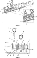
- the cartridges in particular by suitable blow molding, cost-effectively trained in a manufacturing step.
- the chambers of a cartridge can be separated from one another, for example, by webs or material bridges which are formed during or after the blow molding process.
- the cartridge can also be formed in several pieces by injection molded and then assembled components.
- the cartridge is formed in such a multi-piece, that at least one chamber, preferably all chambers, individually from the metering device can be removed or used in the metering device.
- This makes it possible, with a different consumption of a preparation from a chamber to exchange an already empty chamber, while the rest, which may still be filled with preparation, remain in the metering device.
- a targeted and needs-based refilling the individual chambers or their preparations can be achieved.
- the chamber walls can in particular be shaped such that they can be positively connected to one another.
- the cartridges are shaped in such a way that the chambers can be positively connected to one another only in a specific defined position.
- the chambers of a cartridge can be fixed to one another by suitable connection methods, so that a container unit is formed.
- the chambers can be fixed by a suitable form-fitting, non-positive or cohesive connection releasably or permanently against each other.
- the fixation by one or more of the types of compounds from the group of snap-in compounds, Velcro, press joints, fusions, glued joints, welded joints, solder joints, screw, wedge, clamp or bounce joints can be done.
- the fixation can also be formed by a shrink sleeve (so-called sleeve), which is pulled in a heated state over the entire or sections of the cartridge and firmly encloses the chambers or the cartridge in the cooled state.
- the bottom of the chambers may be funnel-shaped inclined towards the discharge opening.
- the inner wall of a chamber can be formed by suitable choice of material and / or surface design in such a way that a low material adhesion of the preparation to the inner chamber wall is realized. Also by this measure, the residual emptiness of a chamber can be further optimized.
- the cartridge may also be asymmetrical. It is particularly preferred to form the asymmetry of the cartridge in such a way that the cartridge can only be coupled to the dosing device in a predefined position in which an otherwise possible incorrect operation by the user is prevented.
- a metering chamber may be formed in a gravity-induced flow direction of the preparation in front of the outlet opening of a chamber.
- the preparation amount the release of preparation from the chamber to the Environment is to be delivered.
- the closure element of the dosing device which causes the preparation output from a chamber to the environment, can only be put into a dispensing and a closure state without measuring or controlling the dispensing quantity. It is then ensured by the metering chamber that a predefined amount of preparation is released without an immediate feedback of the currently discharged, outflowing preparation amount.
- the metering chambers can be formed in one piece or in several pieces. Furthermore, it is possible to firmly connect the metering chambers with the cartridge or detachably. In a dosing chamber detachably connected to the cartridge, it is possible in a simple manner to connect or exchange dosing chambers with different dosing volumes with a cartridge, whereby a simple adaptation of the dosing volumes to the preparation stored in each chamber and thus a simple assembly the cartridge for different preparations and their dosage is possible.
- one or more chambers in addition to a, preferably bottom-side outlet opening each have a liquid-tight sealable, preferably head-side second chamber opening. Through this chamber opening, it is possible, for example, to refill stored in this chamber preparation.
- ventilation possibilities can be provided in particular in the head region of the cartridge in order to ensure a pressure equalization with decreasing filling level of the chambers between the interior of the cartridge chambers and the environment.
- These ventilation options can be designed, for example, as a valve, in particular silicone valve, micro-openings in a chamber or cartridge wall or the like.
- the cartridge chambers are not ventilated directly but are provided via the metering device or no ventilation, for example when using flexible containers such as bags, this has the advantage that at elevated temperatures during a dishwashing cycle of a dishwasher by the heating of the chamber contents, a pressure is built up, which presses the preparations to be metered in the direction of the outlet openings, so that a good emptying of the cartridge can be achieved. Furthermore, in the case of such an air-free packaging, there is no risk of oxidation of substances of the preparation, which makes bag packaging or else bag-in-bottle packaging appear expedient, in particular for oxidation-sensitive preparations.
- the volume ratio formed from the volume of construction of the metering device and the filling volume of the cartridge ⁇ 1, more preferably ⁇ 0.1, particularly preferably ⁇ 0.05. This ensures that, for a given total construction volume of metering device and cartridge, the overwhelming portion of the construction volume is taken up by the cartridge and the preparation contained therein.
- the cartridge can take on any spatial form. It can for example be cube-shaped, spherical or plate-like.
- the cartridge and the dosing device can in particular be configured with respect to their spatial form such that they ensure the least possible loss of useful volume, in particular in a dishwasher.
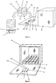
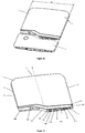
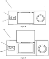
- the dispenser in dishwashers, it is particularly advantageous to mold the device based on dishes to be cleaned in dishwashers. So this example, plate-shaped, be formed in approximately the dimensions of a plate. As a result, the metering device can save space, e.g. be positioned in the lower basket of the dishwasher. Furthermore, the correct positioning of the dosing unit opens up to the user intuitively through the plate-like shape.
- the dosing device and the cartridge preferably have a ratio of height: width: depth of between 5: 5: 1 and 50: 50: 1, particularly preferably of about 10: 10: 1. Due to the "slim" design of the dosing device and the cartridge, it is possible in particular to position the device in the lower cutlery basket of a dishwasher in the receptacles provided for plates. This has the advantage that the dispensed from the dosing preparations go directly into the wash liquor and can not adhere to other items to be washed.
- the metering system is dimensioned in an advantageous embodiment of the invention such that a positioning of the metering only in the appropriate receptacles of the lower basket is enabled.
- the width and the height of the metering system can be selected in particular between 150 mm and 300 mm, particularly preferably between 175 mm and 250 mm.
- the metering unit in cup shape or pot shape with a substantially circular or square base.
- the outlet openings of a cartridge are preferably arranged in a line, whereby a slender, plate-shaped design of the dosing device is made possible.
- the cartridge is advantageous to form the cartridge at least in sections of a transparent material.
- Another way to reduce the effect of heat on a preparation in a chamber of the cartridge is to isolate the chamber by suitable means, e.g. by the use of thermal insulation materials such as styrofoam, which enclose the chamber or the cartridge in a suitable manner, in whole or in part.
- suitable means e.g. by the use of thermal insulation materials such as styrofoam, which enclose the chamber or the cartridge in a suitable manner, in whole or in part.
- Another measure for protecting heat-sensitive substances in a cartridge is, in a plurality of chambers, their arrangement to each other.
- the chamber containing a heat-sensitive product is partially or completely enclosed by at least one further product-filled chamber, which product and chamber functions as thermal insulation for the enclosed chamber in this configuration.
- a first chamber, which contains a heat-sensitive product is partially or completely enclosed by at least one further product-filled chamber, so that the heat-sensitive product in the first chamber has a slower temperature increase when the environment is heated than the one Products in the surrounding chambers.
- the chambers can be arranged around each other according to the matryoshka principle, so that a multilayer insulation layer is formed.
- At least one preparation which is stored in an enclosing chamber, has a thermal conductivity of between 0.01 and 5 W / m * K, preferably between 0.02 and 2 W / m * k, particularly preferably between 0.024 and 1 W / m * K.
- the cartridge is formed in particular dimensionally stable.
- the cartridge is also conceivable to design the cartridge as a flexible packaging such as a tube.
- flexible containers such as bags, especially if they are used according to the "bag-in-bottle" principle in a substantially dimensionally stable receptacle.
- the cartridge has an RFID tag that contains at least information about the contents of the cartridge and that can be read by a sensor unit, which may be provided in particular in the metering device or dishwasher.
- This information can be used, for example, to select a dosing program stored in the dosing unit control unit. In this way it can be ensured that an optimal dosing program is always used for a particular preparation. It can also be provided that in the absence of an RFID tag or an RFID tag with a false or faulty identifier, no metering is done by the metering device and instead an optical or acoustic signal is generated that the user to the present Error indicates.
- the cartridges may also have structural elements which interact with corresponding elements of the metering device according to the key-lock principle, so that, for example, only cartridges of a particular type can be coupled to the metering device. Furthermore, this configuration makes it possible for information about the cartridge coupled to the dosing device to be transmitted to the control unit of the dosing device, as a result of which control of the dosing device coordinated with the contents of the corresponding container can take place.
- the cartridge is designed in particular for receiving flowable cleaning agent. Particularly preferably, such a cartridge has a plurality of chambers for the spatially separated recording in each case of different preparations of a cleaning agent. Exemplary - but not exhaustive - are listed below some possible combinations of filling the chambers with different preparations: Chamber 1 Chamber 2 Chamber 3 Chamber 4 A Alkaline cleaning preparation Enzymatic cleaning preparation - - B Alkaline cleaning preparation Enzymatic cleaning preparation rinse aid - C Alkaline cleaning preparation Enzymatic cleaning preparation rinse aid perfume D Alkaline cleaning preparation Enzymatic cleaning preparation rinse aid disinfecting preparation e Alkaline cleaning preparation Enzymatic cleaning preparation rinse aid pretreatment preparation
- all preparations are flowable, as this ensures rapid dissolution of the preparations in the washing liquor of the dishwasher, whereby these preparations a rapid to immediate cleaning or rinsing, especially on the walls of the washing compartment and / or a Achieve light guide of the cartridge and / or the dosing device.
- the cartridge usually has a total filling volume of ⁇ 5,000 ml, in particular ⁇ 1,000 ml, preferably ⁇ 500 ml, more preferably ⁇ 250 ml, most preferably ⁇ 50 ml.
- the chambers of a cartridge may have the same or different filling volumes.
- the chamber volume ratio is preferably 5: 1, preferably 4: 1: 1 for a three chamber configuration, which configurations are particularly suitable for use in dishwashers.
- the cartridge preferably has three chambers.
- one chamber contains an alkaline cleaning preparation, another chamber an enzymatic preparation and a third chamber a rinse aid, wherein the volume ratio of the chambers is approximately 4: 1: 1.
- the chamber containing the alkaline cleaning preparation preferably has the largest filling volume of the existing chambers.
- the chambers which have a store enzymatic preparation or a rinse aid, in about the same filling volumes.
- a two- and / or three-chamber design of the cartridge is in particular possible to stockpile in particular a perfume, disinfectant and / or Vor harmonyszurung in a detachably arranged on the cartridge or the dosing, another chamber.
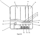
- the cartridge comprises a cartridge bottom, which is directed in the position of use in the direction of gravity down and on which preferably at least one outlet opening arranged in the direction of gravity at the bottom is provided for each chamber.
- the outlet openings arranged on the bottom side are in particular designed such that at least one, preferably all, outlet openings can communicate with the inlet openings of the dosing device, ie preparation via the outlet openings from the cartridge into the dosing device, preferably gravitationally effected, can flow in.
- one or more chambers have a not arranged in the direction of gravity bottom outlet opening. This is particularly advantageous if, for example, a fragrance is to be delivered to the environment of the cartridge.
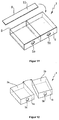
- the cartridge is preferably formed from at least two elements connected to one another in a material-locking manner, wherein the connecting edge of the elements on the cartridge bottom extends outside the outlet openings, that is to say the connecting edge does not intersect the outlet openings.
- the cohesive connection can be produced for example by gluing, welding, soldering, pressing or vulcanization.
- the cartridge elements it is particularly preferable to connect the cartridge elements to one another by means of mirror welding.
- the boundary surfaces are heated by means of a metallic heating mirror, which contains the contour which brings the interfaces into contact, and shortly put into the plastic state, so that after removal of the heating mirror and joining of the parts, these plastic areas solidify again as a melt and solidify Connection result.
- individually molded parts can also be connected to each other by means of laser welding.
- laser welding one of the two materials that are to be melted at the interface must wear an absorbent to absorb the energy content of the laser beam and convert it into heat, which then melts the corresponding material area causes. This is typically accomplished with color pigments that thermally interact with the laser beam conducted into the material. These interfaces to be joined may also be obscured if the material in front of them in the direction of irradiation of the laser beam is transparent to the laser beam and has no absorption property.
- the connecting edge extends along the top, bottom and side surfaces of the cartridge.
- two cartridge elements can be produced in particular by injection molding, wherein either both elements are trough-shaped or an element trough-shaped and the second element is lid-like.
- At least one of the two cartridge elements can comprise at least one separating web which, in the assembled state of the elements, separates two adjacent chambers of the cartridge from one another.
- a cartridge element to be a cup-shaped container having at least one chamber and the second element to be the cartridge bottom or head connected in a fluid-tight manner to the cup-shaped container along the connecting edge.
- such a further chamber for accommodating a preparation may be arranged on the cartridge and be configured in such a way that a release of volatile substances such as, for example, fragrances from the preparation into the environment of the chamber is effected.
- the outlet openings of the cartridge are closed by closure means at least in the filled, unopened state of the cartridge.
- the closure means may be designed such that they allow a single opening of the outlet opening by destruction of the closure means.
- Such closure means are, for example, sealing foils or caps.
- the outlet openings are each provided with a closure which is in the coupled with a dosing device a state Outflow of preparation from the respective chambers allowed and in the uncoupled state of the cartridge substantially prevents leakage of preparation.
- a closure is designed as a slotted silicone valve.
- the ventilation openings of the cartridge are closed with a closure element before a first coupling with the dosing device.
- the closure element may in particular be a stopper or a cap which, when first coupled with the dosing device, is opened, for example punctured, by the coupling process.
- the cartridge elements forming the cartridge are preferably formed from a plastic and can be formed in a common injection molding process, it may be advantageous to form a hinge acting as a connecting web between the two elements, so that after molding the two elements abut each other by folding and cohesively connected along the connecting edge.
- an energy source in particular a battery or accumulator, is arranged on or in the cartridge, preferably on or in the bottom of the cartridge. Furthermore, means for electrically coupling the energy source with the dosing device can be provided on the cartridge.
- the cartridge comprises at least two chambers, very particularly preferably at least three chambers.
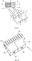
- one ventilation opening and one discharge opening are provided for each chamber.
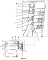
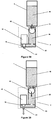
- the bottom-side ventilation opening is communicatively connected to a ventilation duct whose end facing away from the ventilation opening in the dispensing position of the cartridge coupled to the dosing device opens above the maximum fill level of the cartridge.
- the ventilation duct is completely or partially formed in or on the walls and / or webs of the cartridge.
- the ventilation channel can be integrally formed in or on the walls and / or webs of the cartridge.
- the ventilation duct can advantageously be formed by joining at least two elements forming the cartridge.
- a ventilation duct may be formed by joining a separating web of the cartridge formed in the shell-shaped element with two webs which surround the separating web and are arranged on the cartridge element.
- the ventilation channel is formed by integral joining, in particular by welding, of a separating web of the cartridge formed in the shell-shaped element with two webs which surround the separating web and are arranged on the cartridge element.
- the ventilation duct for example, as so-called. Be formed dip-tube.
- the level level (F) of the cartridge in the unopened, filled state of the cartridge with an inclination of up to 45 ° is not present at the ventilation duct mouth (83).
- the viscosity of a flowable preparation and the ventilation duct are configured in such a way that the preparation is not drawn via capillary forces in the ventilation duct when the preparation at the Vent duct opening is present.
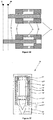
- the coupling of the cartridge with the dosing device is advantageously to be designed such that a dosing device communicating with the inlet opening of the dosing device is arranged on the dosing device, which cooperates with the dockable cartridge or cartridge chamber in such a way that when coupling the ventilation opening of the cartridge or Cartridge chamber with the dosing of the mandrel displaced a volume .DELTA.v in the ventilation duct, whereby a pressure .DELTA.p is generated in the ventilation duct, which is suitable to transport in the ventilation duct, flowable preparation in the connected to the ventilation duct, preparation-storing chamber.
- vent opening of a chamber is communicatively connected to the metering device side mandrel before the closed outlet opening of the corresponding chamber is opened, for example by the communicating connection with the inlet opening of the metering device.
- a ventilation chamber is arranged between the ventilation opening and the ventilation channel.
- the cartridge may be designed such that it can be detachably or firmly arranged in or on the dosing device and / or a dishwasher.
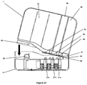
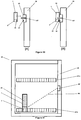
- the dispenser for dispensing at least one flowable detergent preparation inside a household appliance comprises a cartridge coupled to the dispenser wherein the cartridge at least a flowable detergent preparation stored and the cartridge in the direction of gravity bottom side has at least one outlet opening in the with the metering device coupled state is communicatively connected to an inlet opening of the metering device, wherein the metering device and the cartridge have means which cooperate in such a way that a releasable locking between metering device and cartridge can be produced, wherein the metering device and the cartridge in the locked state against each other a pivot point (SP) are pivotable, and that the outlet opening of the cartridge and the inlet opening of the metering console are configured such that they intervene after the production of the latching Cartridge and dosing device are connected communicating by pivoting the cartridge in the coupling state between dosing console and cartridge.
- SP pivot point
- outlet openings of the chambers and the inlet openings of the metering device are arranged and configured such that they are sequentially connected to each other by the pivoting in the latching state in the coupling state of metering device and cartridge.
- means may be provided on the dosing device and / or the cartridge which, in the coupling state of the dosing device and the cartridge, effect a releasable fixing of the cartridge to the dosing device.
- This can be realized, for example, by a collar running on the bottom of the cartridge, which is set back slightly relative to a corresponding dosing device-side collar, so that it is guided on the cartridge-side collar inside the dosing device-side collar.
- the outlet openings of the chambers are arranged one behind the other in the pivoting direction. It is very particularly preferred that the outlet openings of the chambers are arranged in the pivoting direction on a line (L).
- outlet openings of the chambers have approximately the same distance from each other.
- At least two chambers of the cartridge may have different volumes from each other.
- the chamber of the cartridge with the largest volume on the largest distance from the pivot point (SP) of the cartridge 1.
- the ventilation opening of a chamber in the pivoting direction when coupling the cartridge with the dosing device is in each case in front of an outlet opening of the chamber.
- the ratio of depth (T) of the cartridge to width (B) of the cartridge is about 1:20.
- the ratio of height (H) of the cartridge to width (B) of the cartridge is preferably about 1: 1.2.
- the ventilation opening of a chamber in the pivoting direction when coupling the cartridge with the metering device is in each case in front of an outlet opening of the chamber.
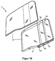
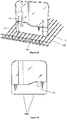
- the cartridge for coupling with a dosing device for dispensing at least one cleaning agent preparation from the cartridge into the interior of a household appliance comprises in a preferred embodiment of the invention a light conductor arranged in or on the cartridge, into which a light signal from outside the cartridge can be coupled. It is particularly preferred to couple a light signal that is emitted from the dosing device into the cartridge.
- the light guide may be wholly or partly formed in or on the walls and / or webs of the cartridge.
- the light guide integrally in or on the walls and / or webs of the cartridge.
- the light guide preferably consists of a transparent plastic material. However, it is also possible to form the entire cartridge from a transparent material.
- the light guide is capable of directing light in the visible range (380-780 nm). It is especially preferable that the light guide is suitable for directing light in the near infrared range (780nm-3,000nm). In particular, it is preferred that the light guide is suitable for guiding light in the mid-infrared range (3.0 ⁇ m-50 ⁇ m).
- the light guide consists of a transparent plastic material with a high refractive index.
- the light guide is at least partially completely or partially enclosed by a material having a lower optical refractive index.
- the lower refractive index material may be a preparation stored in a chamber of the cartridge.
- a ratio of the refractive indices of preparation and light guide of 1: 1.10 - 1: 5, preferably, 1: 1.15 - 1: 1.35, particularly preferably 1: 1.15 - 1: 1.20 , where the refractive index was determined in each case at a wavelength of 589 nm.
- the refractive index of the light guide can be determined, for example, according to DIN EN ISO 489.
- the refractive index of the preparation can be determined by means of an Abbe refractometer according to DIN 53491.
- the preparation which completely or partially encloses the light guide has a transmittance of 45% -95%, particularly preferably 60% -90%, very particularly preferably 75% -85%.
- the light guide preferably has a transmittance of> 75%, very particularly preferably> 85%.
- the transmittance can be determined according to DIN5036.
- the wavelength of the light which is transmitted through the optical waveguide corresponds approximately to the wavelength of at least one preparation which at least partially surrounds the optical waveguide, which is not absorbed from the visible spectrum by the preparation. It is particularly preferable here that the wavelength of the light transmitted through the optical fiber and the wavelength not absorbed by the preparation is between 600-800 nm.
- the light signal which can be coupled into the optical waveguide is in particular a carrier of information, in particular, for example, with respect to the operating state of the dosing device and / or the filling level of the cartridge.
- the light guide is designed in such a way that the light signal which can be coupled into the light guide can also be decoupled from the light guide.
- the light guide may be configured in such a way that the light signal can be coupled out at a position of the cartridge which is different from the point in which the light signal can be coupled into the cartridge.
- the coupling or decoupling of the light signal can be realized in particular on a prismatic edge of the cartridge.
- the distance of the light source arranged in the dosing device, in particular an LED, to the point of introduction of the light into the cartridge in the coupling state of the cartridge and dosing device should be kept as low as possible.
- the light signal and the light guide are configured in such a way that a visible to a user light signal to and / or can be generated in the cartridge.
- the light guide can be severed at at least one point in the cartridge in such a way that preparation can fill the separation point.
- a fill level sensor and / or an inclination sensor can be realized in a simple manner, wherein a light signal that passes through the separation point without preparation differs from the light signal that passes through the separation point completely or partially filled with preparation.
- a sensor unit and / or a power source is also arranged on or in the metering device.
- the dosing device consists of a splash-proof housing, that the penetration of water spray, as may occur, for example, when used in a dishwasher, in the interior of the dosing device by at least the control unit, sensor unit and / or actuator are arranged prevented.
- potting materials for example, multicomponent epoxy, and acrylate potting compounds such as methacrylate esters, urethane-metha and cyanoacrylates or two-component materials can be used with polyurethanes, silicones, epoxy resins.
- the material from which the dosing device is formed prevents or at least reduces the growth of a biofilm.
- the material known from the prior art it is possible to use corresponding surface structures of the material known from the prior art, and additives such as biocides.
- the dosing device comprises at least a first interface, which cooperates in or on a household appliance, in particular t a dishwasher formed corresponding interface in such a way that transmission of electrical energy and / or signals from the household appliance to the dosing and / or Dosing to household appliance is realized.
- the interfaces are formed by connectors.
- the interface cells can be designed in such a way that a wireless transmission of electrical energy and / or electrical and / or optical signals is effected.
- the interfaces provided for the transmission of electrical energy are inductive transmitters or receivers of electromagnetic waves.
- the interface of a dishwashing machine can be designed as an alternating current transmitter coil with iron core and the interface of the metering device as a receiver coil with iron core.
- the transmission of electrical energy can also be provided by means of an interface, the household appliance side, an electrically operated light source and dosier confuse wheier yogurt.
- a light sensor such as a photodiode or a solar cell comprises.
- the light emitted by the light source is converted by the light sensor into electrical energy, which in turn feeds, for example, a metering device side accumulator.
- an interface on the dosing device and the water-conducting device for transmitting (ie transmitting and receiving) electromagnetic and / or optical signals, which in particular Radios-, measuring and / or control information of the dosing and / or the water-bearing device such as a dishwasher.
- such an interface can be designed such that a wireless transmission of electrical energy and / or electromagnetic and / or optical signals is effected.
- At least one interface is configured to emit and / or receive optical signals in the wavelength range between 600-800nm. Since darkness usually prevails in the interior of the dishwasher during operation of a dishwasher, signals in the visible, optical region, for example in the form of signal pulses or light flashes, can be emitted and / or detected by the dosing device. It has proven particularly advantageous to use wavelengths between 600-800 nm in the visible spectrum.
- the interface comprises at least one LED.
- the interface comprises at least two LEDs. It is also possible according to a further preferred embodiment of the invention to provide at least two LEDs which emit light in a mutually different wavelength. This makes it possible, for example, to define different signal bands on which information can be sent or received.
- At least one LED is an RGB LED whose wavelength is adjustable.
- an LED can be used to define different signal bands that emit signals at different wavelengths.
- light is emitted at a different wavelength during the drying process, during which there is a high level of atmospheric humidity (mist) in the washing compartment, than, for example, during a washing step.
- the interface of the dosing device can be configured such that the LED is provided both for emitting signals inside the dishwasher, in particular when the dishwasher door is closed, and also for visually displaying an operating state of the dosing device, in particular when the dishwasher door is open.
- an optical signal is designed as a signal pulse with a pulse duration between 1 ms and 10 seconds, preferably between 5 ms and 100 ms seconds.
- the interface of the dosing device is configured such that it emits an optical signal with the dishwasher closed and unloaded, that a mean illuminance E between 0.01 and 100 lux, preferably between 0.1 and 50 lux measured on the causes the Spülraum limiting walls.
- This illuminance is then sufficient to cause multiple reflections with or on the other Spipporaumassin and so possible signal shadows in the washing compartment, in particular in the loading condition of the dishwasher to reduce or prevent.
- the signal transmitted and / or received by the interface is in particular a carrier of information, in particular a control signal or a signal representing an operating state of the dosing device and / or the dishwasher.
- the dosing device for dispensing at least one washing and / or cleaning agent preparation from a cartridge into the interior of a domestic appliance has a light source, by means of which a light signal can be coupled into a light guide of the cartridge.
- the light source may be an LED.
- the corresponding light signals can for example be slid into the head of the cartridge, so that even if the dosing is positioned in the plate receptacle between other items to be washed, the light signals are visually perceptible by the user with proper loading of the dish drawer of the head-side portion of the dishes and the cartridge usually remains uncovered.
- the light signal coupled into the optical waveguide of the cartridge and passing through the optical waveguide to be detectable by a sensor located on the dosing device. This will be explained in more detail in a subsequent section.
- the dosing device for dispensing at least one washing and / or cleaning agent preparation inside a household appliance comprises at least one optical transmitting unit, wherein the optical transmitting unit is configured in such a way that signals from the transmitting unit in a coupled with the dosing device Cartridge can be coupled and signals from the transmitting unit in the environment of the dosing device are radiated.
- the optical transmitting unit is configured in such a way that signals from the transmitting unit in a coupled with the dosing device Cartridge can be coupled and signals from the transmitting unit in the environment of the dosing device are radiated.
- the optical transmitting unit may be an LED, which preferably emits light in the visible and / or IR range. It is also conceivable to use another suitable optical transmitting unit, e.g. a laser diode, to use. It is necessary to use an optical transmitter which emits light in the wavelength range between 600-800nm.
- the dosing device may comprise at least one optical receiving unit.
- the dosing device can receive signals from an optical transmission unit arranged in the household appliance.
- This can be realized by any suitable optical receiving unit, such as photocells, photomultipliers, semiconductor detectors, photodiodes, photoresistors, solar cells, phototransistors, CCD and / or CMOS image sensors.
- the optical receiver unit is suitable to receive light in the wavelength range of 600-800nm.
- the optical receiving unit on the dosing device can also be configured such that the signals that can be coupled from the transmitting unit into a cartridge coupled to the dosing device can be decoupled from the cartridge and detected by the optical receiving unit of the dosing device.
- the signals emitted by the transmitting unit into the surroundings of the metering device may preferably represent information regarding operating conditions or control commands.
- the metering device for dispensing at least one flowable detergent and / or cleaning agent preparation into the interior of a domestic appliance may in particular have a metering chamber communicating with the metering device communicating cartridge connected to a metering device in the metering chamber inlet, so that in the position of use of the metering preparation gravitational effects the cartridge is inserted into the metering chamber with a Dosierhuntauslass downstream of the Dosierhunteinlass which can be closed by a valve in the metering a float is arranged whose density is less than the density of the preparation, wherein the float is formed in the manner in that the preparation can circumnavigate and / or flow through the floating body and the floating body and the metering chamber inlet are configured in such a way that the metering chamber inlet can be closed by the floating body.
- the float can the Dosierhunteinlass sealing or not sealing.
- a non-sealing closure of the float is indeed at the Dosierhunteinlass, but this seals not against inflow of preparation from the cartridge, so that an exchange of preparation between the cartridge and the metering chamber is possible.
- the float body acts in this embodiment of the invention as a targeted throttle, which minimizes the slippage between the metering chamber inlet and the metering chamber outlet when opening the valve and thus determines the metering accuracy.
- the float and the metering chamber can be designed as a self-closing valve, on the one hand, in order to bring about the lowest possible energy consumption in an energy self-sufficient dosing device; on the other hand, a defined amount of preparation, which corresponds approximately to the filling volume of the dosing, released.
- the density of the detergent and / or cleaning agent preparation and the density of the floating body such that the floating body has a rate of rise of 1.5 mm / sec to 25 mm / sec, preferably 2 mm / sec to 20 mm / sec, in particular preferably 2.5 mm / sec to 17.5 mm / sec in the washing and / or cleaning agent preparation. This ensures a sufficiently rapid closing of the metering chamber inlet by the ascending float and thus a sufficiently short interval between two preparation dosages.
- the rate of climb of the floating body can advantageously also be stored in the control unit of the dosing device which activates the valve. This makes it possible to connect the valve so that a release of preparation is greater than the volume of the metering realized. In this case, the valve is then reopened before the float reaches its upper closure position at Dosierhunteinlass and closes the Dosierhunteinlass.
- the floating body and the metering chamber are configured such that in the delivery position of the valve associated with the metering chamber outlet, the rate of rise of the floating body in the washing and / or detergent preparation is smaller than the flow rate of the preparation surrounding the float from the metering chamber.
- the float is preferred to form substantially spherical.
- the float may also be substantially cylindrical.
- the metering chamber is substantially cylindrical. Furthermore, it is advantageous that the diameter of the metering chamber is slightly larger as the diameter of the cylindrical or spherical floating body, so that a slip between the metering chamber and floating body arises with respect to the preparation.
- the float is made of a foamed, polymeric material - in particular of foamed PP - formed.
- the metering chamber is L-shaped.
- a diaphragm between the Dosierhunteinlass and Dosierhuntauslass be arranged, wherein the aperture is formed such that it is sealingly or non-sealingly closed by the float, the float is preferably disposed between the aperture and the Dosierhunteinlass.
- the dosing device comprises a component carrier on which at least the actuator and the closure element and the energy source and / or the control unit and / or the sensor unit and / or the dosing chamber are arranged.
- the component carrier has receptacles for the said components and / or the components are formed integrally with the component carrier.
- the receptacles for the components in the component carrier can be provided for a positive, positive and / or cohesive connection between a corresponding component and the corresponding receptacle.
- the energy source, the control unit and the sensor unit are arranged in a module on or in the component carrier.
- the energy source, the control unit and the sensor unit are combined in an assembly. This can be realized, for example, in that the energy source, the control unit and the sensor unit are arranged on a common electrical printed circuit board.
- the component carrier is designed trough-like, manufactured as an injection molded part. It is particularly preferred that the metering chamber is formed integrally with the component carrier.
- the component carrier By the component carrier a largely simple automatic assembly with the necessary components of the dosing device is possible.
- the component carrier can be prefabricated as a whole, preferably automatically and assembled to form a dosing device.
- the trough-like component carrier can be closed in accordance with an embodiment of the invention after the assembly liquid-tight of a, for example, cover-like closure element.
- the closure element may be formed, for example, as a film which is liquid-tight, materially connected to the component carrier and forms one or more liquid-tight chambers with the trough-like component carrier.
- the closure element can also be a console, in which the component carrier can be inserted, wherein the console and the component carrier in the assembled state form the dosing device.
- the component carrier and the console in the assembled state cooperate in such a way that between the component carrier and the console, a liquid-tight connection is formed, so that no rinse water can get into the interior of the dosing device or the component carrier.
- the receptacle for the actuator on the component carrier in the direction of gravity is arranged above the metering chamber, whereby a compact design of the metering device can be realized.
- the compact design can be further optimized by the Dosierhunteinlass is arranged on the component carrier above the receptacle of the actuator in the position of use of the dosing device.
- the components it is also preferable for the components to be arranged on the component carrier substantially in a row relative to one another, in particular along the longitudinal axis of the component carrier.
- the receptacle for the actuator has an opening which is in line with the Dosierhuntauslass so that a closure element from the actuator through the opening and the Dosierhuntauslass can be moved back and forth.
- the component carrier is formed of a transparent material.
- the component carrier comprises at least one optical waveguide, via which light from the environment of the dosing device can be directed to an optical transmitting and / or receiving unit into and / or out of the interior (s) of the dosing device or the component carrier, the optical waveguide in particular is formed integrally with the transparent component carrier.
- At least one opening is provided in the dosing device, by means of which light from the environment of the dosing device in and / or out of the optical waveguide can be coupled in and / or out.
- an actuator is a device which converts an input variable into a different output quantity and with which an object is moved or whose movement is generated, wherein the actuator is coupled to at least one shutter element, directly or indirectly releasing the preparation at least one cartridge chamber can be effected.
- the actuator may be driven by drives selected from the group of gravity drives, ion drives, electric drives, motor drives, hydraulic drives, pneumatic drives, gear drives, threaded spindle drives, ball screws, linear drives, roller screws, tooth worm drives, piezoelectric actuators, chain drives, and / or recoil drives.
- drives selected from the group of gravity drives, ion drives, electric drives, motor drives, hydraulic drives, pneumatic drives, gear drives, threaded spindle drives, ball screws, linear drives, roller screws, tooth worm drives, piezoelectric actuators, chain drives, and / or recoil drives.
- the actuator may be formed of an electric motor coupled to a transmission that converts the rotational movement of the motor into a linear motion of a carriage coupled to the transmission. This is particularly advantageous for a slim, plate-shaped design of the dosing unit.
- At least one magnetic element can be arranged on the actuator, which causes a product discharge from the container with a magnet element with the same polarity on a dispenser as soon as the two magnetic elements are positioned against one another such that magnetic repulsion of the homopolar magnetic elements is effected and a non-contact release mechanism is realized.
- the actuator is a bistable solenoid, which forms a pulse-controlled, bi-stable valve together with an engaging in the bistable solenoid, designed as a plunger core closure element.
- Bistable lifting magnets are electromechanical magnets with linear direction of movement, wherein the plunger locked in each end position without current.
- Bistable lifting magnets or valves are known in the art.
- a bistable valve requires a pulse to change valve positions (open / closed) and then remains in that position until a counter pulse is sent to the valve. Therefore, one speaks of a pulse-controlled valve.
- a significant advantage of such pulse-controlled valves is that they do not consume energy to dwell in the Ventilendlagen, the closed position and discharge position, but only need an energy pulse to change the valve layers, thus the Ventilendlagen are considered to be stable.
- a bistable valve remains in that switching position, which last received a control signal.
- the closure element By means of a current pulse, the closure element (plunger core) is moved to an end position. The power is switched off, the closing element holds the position. By current pulse, the closure element is moved to the other end position. The power is switched off, the closing element holds the position.
- a bistable property of solenoids can be realized in different ways.
- a division of the coil is known.
- the coil is split more or less centrally so that a gap is created.
- a permanent magnet is used.
- the plunger core itself is both the front and the back so turned off that he has in the respective end position a flat surface lying to the frame of the magnet.
- the magnetic field of the permanent magnet flows over this surface.
- the diving core sticks here.
- the use of two separate coils is possible.
- the principle is similar to the bistable solenoid with split coil. The difference is that they are actually two electrically different coils. These are controlled separately, depending on the direction in which the plunger is to be moved.
- the closure element is coupled to the actuator in such a way that the closure element from the actuator in a closed position and in a passage position (dispensing position) is displaceable, wherein the closure element is designed as open / close valve element, that the actuator is designed such that it controlled by a suitable pulse selectively determinable occupies one of two end positions and without activation, the reached end position stably maintained, and thus that the combination forms a pulse-controlled, bistable open / close valve.
- the actuator may for this purpose be designed as a bistable solenoid with an armature receiving space and a surrounding outer receiving space.
- the armature of the bistable solenoid may be configured to form or couple to the closure element.
- the armature receiving space of the actuator from the outer receiving space of the actuator may be liquid-tight and preferably also gas-tight.
- At least the outer surface of the armature from a material which can not be attacked by the washing or cleaning agent to be metered, in particular from a plastic material.
- the armature preferably comprises a core of a magnetizable, in particular a ferromagnetic material and a permanent magnet positioned in the outer receiving space, wherein a coil is arranged at each of its two axial ends.
- permanent magnets are arranged axially antipolig and that in the outer receiving space at both axial ends yoke rings of a ferromagnetic material, in particular iron, and between these a coil winding are arranged.
- the axial distance of the yoke rings is greater than the axial distance of the permanent magnets.
- Further yoke rings can be arranged in the armature at its axial ends, wherein in the outer receiving space at both axial ends of permanent magnets are arranged axially antipolig and between these a coil winding is arranged.
- the axial distance of the permanent magnets is in this case preferably greater than the axial distance of the yoke rings.
- the one actuator / closure element combination is provided in a metering device of a metering system with a cartridge for flowable washing or cleaning agent having a plurality of chambers for spatially separated receiving each different preparations of a detergent or cleaning agent and with a detachable with the cartridge
- the dosing device comprises: a power source, a control unit, a sensor unit, an actuator, which is so connected to the power source and the control unit, that a control signal of the control unit causes an actuation of the actuator, a closure element, with the actuator in the Art is coupled so that it is displaceable by the actuator in a Verschetz ein and in a passage position (dispensing position), at least one metering chamber communicating communicates with at least one of the cartridge chambers of the cartridge in a combined with a cartridge dosing en, wherein the metering chamber has an inlet for the inflow of detergent or cleaning agent from a Cartridge chamber and an outlet for the discharge of detergent or cleaning agent from the meter
- the actuator is arranged in a component carrier in the manner that in the use position of the metering device, a receptacle for the actuator on the component carrier in the direction of gravity above the metering chamber is arranged.
- the inlet of the dosing chamber is arranged on the component carrier above the receptacle of the actuator.
- the metering device has a component carrier in which a receptacle for the actuator on the component carrier is arranged laterally next to the metering chamber in the use position of the metering device.
- the receptacle for the actuator preferably has an opening which is in line with the outlet of the metering chamber, wherein the closure element from the actuator through the opening to the outlet is movable back and forth.
- a closure element is a component that acts on the actuator and that as a result of this action causes the opening or the closure of an outlet opening.
- the closure element can be valves which can be brought into a product delivery position or closure position by the actuator.
- the embodiment of the closure element and the actuator in the form of a solenoid valve, wherein the dispenser are configured by the valve and the actuator by the electromagnetic or piezoelectric drive of the solenoid valve.
- the amount and timing of the dosage can be controlled very accurately by the use of solenoid valves.
- a sensor is a measuring sensor or measuring sensor which can quantitatively record certain physical or chemical properties and / or the material quality of its environment qualitatively or as a measured variable.
- the dosing unit preferably has at least one sensor which is suitable for detecting a temperature.
- the temperature sensor is designed in particular for detecting a water temperature.
- the dosing unit comprises a sensor for detecting the conductivity, whereby in particular the presence of water or the spraying of water, in particular in a dishwasher, is detected.
- the dosing unit has a sensor which can determine physical, chemical and / or mechanical parameters from the surroundings of the dosing unit.
- the sensor unit may comprise one or more active and / or passive sensors for the qualitative and / or quantitative detection of mechanical, electrical, physical and / or chemical variables, which are passed as control signals to the control unit.
- the sensors of the sensor unit from the group of timers, temperature sensors, infrared sensors, brightness sensors, temperature sensors, motion sensors, strain sensors, speed sensors, proximity sensors, flow sensors, color sensors, gas sensors, vibration sensors, pressure sensors, conductivity sensors, turbidity sensors, Schall Bateldrucksensoren, "Lab-on-a Chip sensors, force sensors, acceleration sensors, inclination sensors, pH sensors, humidity sensors, magnetic field sensors, RFID sensors, magnetic field sensors, Hall sensors, biochips, odor sensors, hydrogen sulfide sensors and / or MEMS sensors.
- Suitable flow sensors may be selected from the group of orifice flow rate sensors, electromagnetic flowmeters, Coriolis mass flow rate measurement, vortex flowmeter, ultrasonic flow rate measurement, variable area flow measurement, annular piston flow measurement, thermal mass flow measurement, or differential pressure flow measurement.
- At least two sensor units are provided for measuring mutually different parameters, with very particular preference a sensor unit is a conductivity sensor and a further sensor unit is a temperature sensor. Furthermore, it is preferred that at least one sensor unit is a brightness sensor.
- the sensors are especially adapted to detect the beginning, the course and the end of a washing program.
- the sensor combinations listed in the following table can be used Sensor 1 Sensor 2 Sensor 3 Sensor 4 conductivity sensor temperature sensor conductivity sensor temperature sensor brightness sensor conductivity sensor temperature sensor brightness sensor turbidity sensor sound sensor temperature sensor
- the conductivity sensor can be detected, for example, whether the conductivity sensor is wetted by water, so that, for example. determine if there is water in the dishwasher.
- Rinsing programs usually have a characteristic temperature profile, the u.a. is determined by the heating of the rinse water and the drying of the dishes, which can be detected by a temperature sensor.
- the light penetration into the interior of a dishwasher can be detected when the dishwasher door is opened, resulting in e.g. indicates an end to the washing program.
- a turbidity sensor can also be provided. From this it is also possible, for example, to select a dosing program in the dosing device that applies to the determined contamination situation.
- a temperature-dependent viscosity curve of at least one preparation to be stored in the control unit, wherein the dosage is adjusted according to the temperature and thus the viscosity of the preparation by the control unit.
- an apparatus for direct determination of the viscosity of the preparation is provided.
- the data line between the sensor and the control unit can be realized via an electrically conductive cable or wirelessly.
- at least one sensor outside the dosing device is positioned or positionable in the interior of a dishwasher and a data line - in particular wireless - for transmitting the measured data from the sensor to the dosing device is formed.
- a wirelessly formed data line is formed in particular by the transmission of electromagnetic waves or light. It is preferable to form a wireless data line according to standardized standards such as Bluetooth, IrDA, IEEE 802, GSM, UMTS, etc.
- At least one sensor unit is arranged on or in the control unit.
- the sensor unit is arranged at the bottom of the dosing device, wherein in the position of use the bottom of the dosing device is directed downward in the direction of gravity.
- the sensor unit comprises a temperature and / or a conductivity sensor.
- the energy consumers of the dosing device in particular the control unit, including an on / off switch can be connected to the power source and the energy source only after reaching the On-state of the on / off switch loaded with a sensor unit forms the on / off switch or is connected to this and switches.
- the sensor unit prefferably has two contacts in contact with the environment at the bottom of the dosing device, in particular configured as contact pins projecting downwards from the bottom, one contact as anode contact and the other contact as cathode contact the power source is connected and that without electrically conductive connection between the contacts of the off-state located on / off switch remains in the off state and upon the emergence of an electrically conductive connection between the contacts of the off-state on / off Switch in the on state switches.
- the on / off switch is provided or combined with a self-holding circuit which ensures latching of the energy supply of the energy consumers after reaching the on state of the on / off switch up to a switch-off signal of the control unit . causes.
- the on / off switch can be designed in particular as a transistor circuit. It is preferable that the transistor of the on / off switch designed as a pnp transistor and the emitter, possibly via a drive circuit, to the supply voltage to the collector, possibly via a drive circuit to ground and to the cathode contact and the base on the one hand, possibly via a drive circuit, to the supply voltage, on the other hand, if necessary via a drive circuit to the anode contact, is connected.
- the drive circuit preferably has at least one drive resistor, which is designed in particular as a resistance voltage divider.
- a sensor unit designed as a conductivity sensor which has two contacts in contact with the environment at the bottom of the dosing device and the anode contact of the on / off Sensor unit is simultaneously the anode contact of the conductivity sensor forming sensor unit.
- the sensor unit forming the temperature sensor may be integrated in a contact, in particular the cathode contact, of the sensor unit forming the conductivity sensor.
- the contact of the sensor unit forming the conductivity sensor, which receives the temperature sensor may preferably be designed as a hollow contact pin, in which the temperature sensor of the sensor unit forming the temperature sensor is arranged.
- the energy source, the control unit and the sensor unit are combined in an assembly on or in the component carrier.
- the contacts of a conductivity sensor arranged on the bottom side are surrounded by an electrically conductive silicone.
- the conductivity sensor may in this case be designed, in particular in the form of a resistance measurement, between two contacts spaced apart from one another and in contact with the surroundings of the dosing device.
- the silicone is flush-mounted in the bottom of the metering device.
- the silicone has an approximately circular base. The silicone shows a good wettability with water and thus provides good measurement results regarding the detection of water in the dishwasher.
- a control unit in the sense of this application is a device which is suitable for influencing the transport of material, energy and / or information.
- the control unit influences actuators with the aid of information, in particular of measuring signals of the sensor unit, which processes them in the sense of the control target.
- control unit may be a programmable microprocessor.
- a plurality of dosing programs is stored on the microprocessor, which are selectable and executable in a particularly preferred embodiment according to the container coupled to the dosing device.
- the control unit has, in a preferred embodiment, no connection to the possibly existing control of the household appliance. There will be no Information, in particular electrical, optical or electromagnetic signals, exchanged directly between the control unit and the control of the household appliance.
- control unit is coupled to the existing control of the household appliance.
- this coupling is wireless.
- a transmitter on or in a dishwasher preferably on or at the dosing chamber embedded in the door of the dishwasher, which wirelessly transmits a signal to the dosing unit when the control of the domestic appliance controls the dosing of, for example, a detergent from the dosing unit Dosing or rinse aid causes.
- the control unit can store several programs for releasing different preparations or releasing products in different applications.
- the call of the corresponding program can be effected by means of corresponding RFID labels or geometric information carriers formed on the container.
- the same control unit for a plurality of applications, for example for metering detergent in dishwashers, for dispensing perfumes in room fragrancing, for applying cleaning substances to a toilet bowl, etc.
- control unit can be configured in such a way that on the one hand the dosing takes place in a sufficiently short time to ensure a good cleaning result and on the other hand the dosing of the preparation does not occur so quickly.
- This can be realized, for example, by an interval-like release, whereby the individual metering intervals are set in such a way that the corresponding metered amount dissolves completely during a cleaning cycle.
- the metering intervals for dispensing a preparation are between 30-90 seconds, particularly preferably 45-75 seconds.
- the delivery of preparations from the dosing device can be done sequentially or simultaneously.
- the dishwasher and the dosing device work together in such a way that 1 mg to 1 g of surfactant are released in the final rinse program of the dishwasher per m 2 Spülraumwyer Structure. This ensures that the walls of the washing compartment retain their gloss even after a plurality of rinsing cycles and the dosing system retains its optical transmission capability.
- the dishwasher and the dosing device to interact in such a way that at least one enzyme-containing preparation and / or alkaline preparation is released in the pre-washing program and / or main washing program, with the release of the enzyme-containing preparation preferably taking place prior to release the alkaline preparation takes place.
- the dishwasher and the dosing device work together in such a way that 0.1 mg-250 mg of enzyme protein are released in the pre-washing program and / or main wash program of the dishwasher per m 2 of dishwashing area, whereby the gloss level of the dishwashing walls is further improved or improved It is also retained after a large number of rinsing cycles.
- data such as control and / or dosing programs of the control unit or stored by the control unit
- Operating parameters or protocols are read from the control unit or loaded into the control unit.
- This can be realized, for example, by means of the optical interface, wherein the optical interface is correspondingly connected to the control unit.
- the data to be transmitted are then encoded as light signals, in the wavelength range between 600-800nm, and transmitted or received.
- a present in the metering sensor for transmitting data from and / or to the control unit.
- the contacts of a conductivity sensor which are connected to the control unit and which provides a conductivity determination by means of a resistance measurement at the contacts of the conductivity sensor, can be used for data transmission.
- a method for operating a dosing device not connected to a household appliance for dispensing at least one detergent and / or detergent preparation inside the household appliance may be formed, wherein at least one dosing program is stored in the control unit, and the control unit is at least an actuator located in the metering device cooperates in such a way that washing and / or cleaning agent preparation is releasable from the metering device inside the household appliance, the metering device comprises at least one receiving unit for signals emitted by at least one arranged in the household appliance transmitting unit and at least a part the signals in the dosing device-side control unit are converted into control commands for the actuators of the dosing device, the reception of the signals being monitored on the dosing device side by means of the control unit and not receiving the signals on the dosing a dosing from the control unit of the dosing device is activated.
- the household appliance-side signal is emitted in predefined, periodic time intervals from the household appliance-side transmitting unit into the interior of the household appliance.
- the defined periodic intervals in which a signal is emitted from the household appliance-side transmitting unit are stored in the control unit of the metering device and in the household appliance. If the contact between the transmitting unit of the domestic appliance breaks down after receiving a signal at the dosing device, this demolition can be determined by comparing the time elapsed since the last received signal and the time in which periodic time interval, the reception of a subsequent signal is expected to be determined Dosierettifact.
- the periodic signal intervals are selected between 1 second and 10 minutes, preferably between 5 seconds and 7 minutes, more preferably between 10 seconds and 5 minutes. It is particularly preferred that the periodic signal intervals are selected between 3 minutes and 5 minutes.
- control unit of the dosing device after the expiration of a predefined time interval t 1-2 starting at t 1 in which no further appliance signal is received by the dosing device, activates a dosing program from the control unit of the dosing device.
- the control unit evaluates the number and / or time sequence of the signals received by the dosing device in such a way that a dosing program is activated in the control unit in accordance with the evaluation result.
- This makes it possible to determine, for example, the duration of a washing program in a dishwasher since its start by comparing the time of the first signal reception to the time of determining the signal break, so that according to the progress of the washing program, a suitable, the progress of the wash program corresponding dosing in the control unit of the dosing device is activated.
- a dosing program stored in the control unit of the dosing device is activated in the control unit starting from a defined program step corresponding to the progress of the washing program.
- a dosing program in the dosing device during a signal rupture in the main rinse cycle of a rinse program, which is provided for a main rinse cycle and subsequent rinse program sections.
- the signals transmitted by the household appliance-side transmitting unit comprise at least one control signal.
- the signals emitted by the household appliance-side transmitting unit comprise at least one monitoring signal.
- At least one dosing program stored in the control unit comprises a dosing program of the household appliance. This makes it possible that in a signal separation between the household appliance and the dosing unit, the dosing continues a dosing program started by the household appliance.
- the metering programs stored in the control unit of the metering device include the metering programs of the household appliance.
- the transmission of a monitoring signal and / or control signal to the household appliance can be effected manually by a user.
- a user can check, for example, whether there is a signal reception between the transmitting unit of the household appliance and the dosing device in one of his chosen positioning of the dosing within the household appliance.
- This can be realized, for example, by an operating element embodied on the household appliance, such as a pushbutton or switch, which transmits a monitoring and / or control signal when actuated.
- the energy source a component of the dosing, which is expedient to provide a suitable for the operation of the dosing or the dosing energy.
- the energy source is designed such that the dosing system is self-sufficient.
- the energy source provides electrical energy.
- the energy source may be, for example, a battery, an accumulator, a power supply, solar cells or the like.
- a battery may be selected from the group of alkaline manganese batteries, zinc-carbon batteries, nickel-oxyhydroxide batteries, lithium batteries, lithium iron sulfide batteries, Zinc air batteries, zinc chloride batteries, mercury oxide zinc batteries and / or silver oxide zinc batteries.
- Lead accumulators lead dioxide / lead
- nickel-cadmium batteries nickel-metal hydride batteries
- lithium-ion batteries lithium-polymer batteries
- alkaline manganese batteries silver-zinc batteries
- nickel batteries etc.
- Hydrogen batteries zinc bromine batteries, sodium nickel chloride batteries and / or nickel-iron batteries.
- the accumulator can in particular be designed in such a way that it can be recharged by induction.
- mechanical energy sources consisting of one or more coil spring, torsion spring or torsion bar spring, spiral spring, air spring / gas spring and / or elastomer spring.
- the energy source is dimensioned such that the dosing device can go through about 300 dosing cycles before the energy source is exhausted. It is particularly preferred that the energy source can run between 1 and 300 dosing cycles, most preferably between 10 and 300, more preferably between 100 and 300, before the energy source is depleted.
- means for energy conversion can be provided in or on the dosing unit, which generate a voltage by means of which the accumulator is charged.
- these means may be designed as a dynamo, which is driven by the water flows during a rinse cycle in a dishwasher and emits the voltage thus generated to the accumulator.
- an optical transmitting and / or receiving unit is arranged within the dosing device, in particular in or on the component carrier, in order to protect the electrical and / or optical components of the transmitting and / or receiving unit from spray and rinse water.
- a light guide is disposed between the optical transmitting and / or receiving unit and the environment of the dosing, which identifies at least a light transmission of 75%.
- the light guide preferably consists of a transparent plastic with a light transmittance of at least 75%.
- the transmittance of the optical fiber is defined as the transmittance between the surface of the optical fiber at which the light from the environment of the metering device in the Light guide is coupled and the surface at which the light is coupled out of the optical fiber to the optical transmitting and / or receiving unit.
- the transmittance can be determined according to DIN5036.
- the optical waveguide comprises at least one input and / or decoupling point to which light is coupled or decoupled from an optical transmitting and / or receiving unit and / or from the environment of the dosing device.
- the light guide is formed integrally with the component carrier.
- the component carrier is therefore formed of a transparent material.
- an opening is provided in the dosing device.
- the input and / or decoupling point can be arranged in the lateral surface in the bottom or head of the dosing device.
- the light guide can also be constructed in multiple layers and / or in multiple pieces of the same or different materials. It is also possible to provide an air gap between a multi-layered and / or multi-piece molded optical fiber.
- the transmittance of the light guide is understood in a multi-layered and / or multi-piece structure between the surface of the light guide at which the light from the environment of the dosing device is coupled into the light guide and the surface at which the light from the optical fiber to optical transmission and / or receiving unit is decoupled.
- At least two input or extraction points of the light guide are provided with the environment. It is particularly advantageous that the input or extraction points on the dosing device are substantially opposite.
- the dosing system has at least one vibrating atomizer, via which it is possible to transfer a preparation into the gas phase or to keep it in the gas phase.
- the vibrating atomizer via which it is possible to transfer a preparation into the gas phase or to keep it in the gas phase.
- This embodiment is particularly advantageous when used in a dishwashing machine, where a corresponding release of preparation into the gas phase takes place in a closable washing compartment.
- the preparation introduced into the gas phase can be distributed evenly in the washing compartment and deposited on the items to be washed in the dishwasher.
- the preparation released by the vibrating atomizer may be selected from the group of surfactant-containing preparations, enzyme-containing preparations, odor-neutralizing preparations, biocidal preparations, antibacterial preparations.
- the cleaning preparations By applying the cleaning preparations to the washware from the gas phase, a uniform layer of the corresponding cleaning preparation is applied to the washware surface. It is particularly preferred that the entire Spülgutober Design is wetted by the cleaning preparation.
- a preparation by means of the vibrating atomizer on the dishes after the completion of a cleaning program of a dishwasher.
- This may be, for example, an antibacterial preparation or a preparation for the modification of surfaces.
- the metering system according to the invention comprises at least one first aqueous surfactant-containing preparation which in particular has a pH of less than 5.5, preferably less than 4, particularly preferably less than 3.5 (10% solution, 20 ° C.).
- the acidic adjustment of the surfactant phase in particular limescale deposits on the walls of the washing compartment can be prevented, which can reduce the gloss and the reflectivity of the walls.
- it has surprisingly been found that by means of such a surfactant preparation the transmittance of the light guide between the optical transmission and / or receiving unit of the dosing device and the environment of the dosing device can be kept constant over a plurality of rinsing cycles.
- the securing and improvement of a wireless signal transmission for controlling the dosing systems positioned in the washing compartment is ensured according to the invention by means of a specific surfactant-containing preparation to be released in the rinse cycle.
- this preparation is distinguished in particular by its pH below 5.5 (10% solution, 20 ° C.).
- the preparations according to the invention contain acidifying agents.
- the proportion by weight of the acid (s) in the total weight of the preparation according to the invention based on the total weight of the preparation, preferably between 0.05 and 10 wt .-%, preferably between 0.1 and 8 wt .-% and in particular between 0.2 and 5% by weight.
- Suitable acidifying agents are both inorganic acids and organic acids, with particular preference given to organic acids in the context of the present application for reasons of consumer protection and handling safety.
- Particularly preferred organic acids are the mono-, oligo- and polycarboxylic acids, in particular citric acid, acetic acid, tartaric acid, succinic acid, glutaric acid, malonic acid, adipic acid, maleic acid, fumaric acid, oxalic acid and the homo- or copolymeric polycarboxylic acids.
- Organic sulfonic acids such as amidosulfonic acids are also usable.
- Particularly preferred preparations according to the invention contain, based on their total weight, between 0.05 and 10% by weight, preferably between 0.1 and 8% by weight and in particular between 0.2 and 5% by weight of acetic acid and / or citric acid.
- preparations according to the invention may also contain salts of the abovementioned acids as buffer substances.
- Preference is given here to the alkali metal salts and among these in turn the sodium or potassium salts.
- the surfactants form a second essential constituent of preparations according to the invention.
- the group of surfactants also includes, in particular, the nonionic surfactants used with particular preference.
- nonionic surfactants known to the person skilled in the art can be used as nonionic surfactants.
- Suitable nonionic surfactants are, for example, alkyl glycosides of the general formula RO (G) x , in which R is a primary straight-chain or methyl-branched, in particular in the 2-position methyl-branched aliphatic radical having 8 to 22, preferably 12 to 18 carbon atoms and G is the symbol which represents a glycose unit having 5 or 6 C atoms, preferably glucose.
- the degree of oligomerization x which indicates the distribution of monoglycosides and oligoglycosides, is any number between 1 and 10; preferably x is 1.2 to 1.4.
- Nonionic surfactants of the amine oxide type for example N-cocoalkyl-N, N-dimethylamine oxide and N-tallowalkyl-N, N-dihydroxyethylamine oxide, and the fatty acid alkanolamides may also be suitable.
- the amount of these nonionic surfactants is preferably not more than that of the ethoxylated fatty alcohols, especially not more than half thereof.
- nonionic surfactants used either as the sole nonionic surfactant or in combination with other nonionic surfactants are alkoxylated, preferably ethoxylated or ethoxylated and propoxylated fatty acid alkyl esters, preferably having from 1 to 4 carbon atoms in the alkyl chain.
- washing or cleaning agents in particular automatic dishwashing detergents, contain nonionic surfactants from the group of the alkoxylated alcohols.
- the nonionic surfactants used are preferably alkoxylated, advantageously ethoxylated, in particular primary, alcohols having preferably 8 to 18 carbon atoms and on average 1 to 12 moles of ethylene oxide (EO) per mole of alcohol, in which the alcohol radical can be linear or preferably methyl-branched in the 2-position or linear and methyl-branched radicals in the mixture can contain, as they are usually present in Oxoalkoholresten.
- EO ethylene oxide
- alcohol ethoxylates with linear radicals of alcohols of natural origin having 12 to 18 carbon atoms, for example of coconut, palm, tallow or oleyl alcohol, and on average 2 to 8 moles of EO per mole of alcohol are preferred.
- the preferred ethoxylated alcohols include, for example, C 12-14 alcohols with 3 EO or 4 EO, C 9-11 alcohols with 7 EO, C 13-15 alcohols with 3 EO, 5 EO, 7 EO or 8 EO, C 12-18 alcohols with 3 EO, 5 EO or 7 EO and mixtures of these, such as mixtures of C 12-14 -alcohol with 3 EO and C 12-18 -alcohol with 5 EO.
- the stated degrees of ethoxylation represent statistical averages, which may correspond to a particular product of an integer or a fractional number.
- Preferred alcohol ethoxylates have a narrow homolog distribution (narrow range ethoxylates, NRE).
- fatty alcohols with more than 12 EO can also be used. Examples include tallow fatty alcohol with 14 EO, 25 EO, 30 EO or 40 EO.
- ethoxylated nonionic surfactants consisting of C 6-20 monohydroxyalkanols or C 6-20 alkylphenols or C 16-20 fatty alcohols and more than 12 mol, preferably more than 15 mol and in particular more than 20 mol of ethylene oxide per mol Alcohol was used.
- a particularly preferred nonionic surfactant is obtained from a straight-chain fatty alcohol having 16 to 20 carbon atoms (C 16-20 alcohol), preferably a C 18 -alcohol and at least 12 mol, preferably at least 15 mol and especially at least 20 mol of ethylene oxide.
- C 16-20 alcohol straight-chain fatty alcohol having 16 to 20 carbon atoms
- C 18 -alcohol preferably a C 18 -alcohol
- at least 12 mol preferably at least 15 mol and especially at least 20 mol of ethylene oxide.
- the so-called “narrow range ethoxylates” are particularly preferred.
- Nonionic surfactants which have a melting point above room temperature.
- Nonionic surfactants from the group of alkoxylated alcohols are also used with particular preference.
- the nonionic surfactant solid at room temperature preferably has propylene oxide units in the molecule.
- such PO units make up to 25 wt .-%, more preferably up to 20 wt .-% and in particular up to 15 wt .-% of the total molecular weight of the nonionic surfactant from.
- Particularly preferred nonionic surfactants are ethoxylated monohydroxyalkanols or alkylphenols which additionally have polyoxyethylene-polyoxypropylene block copolymer units.
- the alcohol or alkylphenol content of such nonionic surfactant molecules preferably makes up more than 30% by weight, more preferably more than 50% by weight and in particular more than 70% by weight, of the total molecular weight of such nonionic surfactants.
- Preferred agents are characterized in that they contain ethoxylated and propoxylated nonionic surfactants in which the propylene oxide units in the molecule up to 25 wt .-%, preferably up to 20 wt .-% and in particular up to 15 wt .-% of the total molecular weight of the nonionic Make up surfactants.
- surfactants come from the groups of alkoxylated nonionic surfactants, in particular the ethoxylated primary alcohols and mixtures of these surfactants with structurally complicated surfactants such as polyoxypropylene / polyoxyethylene / polyoxypropylene ((PO / EO / PO) surfactants).
- Such (PO / EO / PO) nonionic surfactants are also characterized by good foam control.
- nonionic surfactants with melting points above room temperature contain 40 to 70% of a Polyoxypropylene / polyoxyethylene / polyoxypropylene block polymer blends containing 75% by weight of a inverse block copolymer of polyoxyethylene and polyoxypropylene with 17 moles of ethylene oxide and 44 moles of propylene oxide and 25% by weight of a block copolymer of polyoxyethylene and polyoxypropylene initiated with trimethylolpropane and containing 24 moles of ethylene oxide and 99 moles of propylene oxide per mole of trimethylolpropane.
- nonionic surfactants have been low foaming nonionic surfactants which have alternating ethylene oxide and alkylene oxide units.
- surfactants with EO-AO-EO-AO blocks are preferred, wherein in each case one to ten EO or AO groups are bonded to each other before a block of the other groups follows.
- nichionic surfactants of the general formula in which R 1 is a straight-chain or branched, saturated or mono- or polyunsaturated C 6-24 alkyl or alkenyl radical; each group R 2 or R 3 is independently selected from -CH 3 , -CH 2 CH 3 , -CH 2 CH 2 -CH 3 , CH (CH 3 ) 2 and the indices w, x, y, z independently stand for integers from 1 to 6.
- the preferred nonionic surfactants of the above formula can be prepared by known methods from the corresponding alcohols R 1 -OH and ethylene or alkylene oxide.
- the radical R 1 in the above formula may vary depending on the origin of the alcohol. If native sources are used, the radical R 1 has an even number of carbon atoms and is usually unbranched, the linear radicals being selected from alcohols of natural origin having 12 to 18 C atoms, for example from coconut, palm, tallow or Oleyl alcohol, are preferred.
- Alcohols which are accessible from synthetic sources are, for example, the Guerbet alcohols or methyl-branched or linear and methyl-branched radicals in the 2-position, as they are usually present in oxo alcohol radicals.
- nonionic surfactants in which R 1 in the above formula is an alkyl radical having 6 to 24, preferably 8 to 20, particularly preferably 9 to 15 and in particular 9 to 11 Carbon atoms.
- alkylene oxide unit which is contained in the preferred nonionic surfactants in alternation with the ethylene oxide unit, in particular butylene oxide is considered in addition to propylene oxide.
- R 2 or R 3 are independently selected from - CH 2 CH 2 -CH 3 or -CH (CH 3 ) 2 are suitable.
- Nonionic surfactants of the above formula are preferably used in which R 2 or R 3 is a residue -CH 3 , w and x independently from each other are values of 3 or 4 and y and z are independently of one another values of 1 or 2.
- nonionic surfactants having a C 9-15 alkyl group having 1 to 4 ethylene oxide units followed by 1 to 4 propylene oxide units followed by 1 to 4 ethylene oxide units followed by 1 to 4 propylene oxide units.
- These surfactants have the required low viscosity in aqueous solution and can be used according to the invention with particular preference.
- R 1 -CH (OH) CH 2 O- (AO) w - (A'O) x - (A "O) y - (A"'O) z -R 2 in which R 1 and R 2 independently of one another represents a straight-chain or branched, saturated or mono- or polyunsaturated C 2-40 -alkyl or -alkenyl radical;
- A, A ', A "and A'” independently represent a radical from the group -CH 2 CH 2 , -CH 2 CH 2 -CH 2 , -CH 2 -CH (CH 3 ), -CH 2 -CH 2 -CH 2 -CH 2 , -CH 2 -CH (CH 3 ) -CH 2 -, -CH 2 -CH (CH 2 -CH 3 ); and w, x, y and z are values between 0.5 and 90, where x, y and / or z can also be 0 are preferred according to the invention
- end-capped poly (oxyalkylated) nonionic surfactants which, in accordance with the formula R 1 O [CH 2 CH 2 O] x CH 2 CH (OH) R 2 , in addition to a radical R 1 , which is linear or branched, saturated or unsaturated, aliphatic or aromatic hydrocarbon radicals having from 2 to 30 carbon atoms, preferably having from 4 to 22 carbon atoms, furthermore having a linear or branched, saturated or unsaturated, aliphatic or aromatic hydrocarbon radical R 2 having from 1 to 30 carbon atoms, where x is from 1 to 30 carbon atoms 90, preferably for values between 30 and 80 and in particular for values between 30 and 60.
- R 1 O [CH 2 CH (CH 3 ) O] x [CH 2 CH 2 O] y CH 2 CH (OH) R 2 in which R 1 is a linear or branched aliphatic hydrocarbon radical having 4 to 18 carbon atoms or mixtures thereof R 2 denotes a linear or branched hydrocarbon radical having 2 to 26 carbon atoms or mixtures thereof and x is between 0.5 and 1.5 and y is at least 15.
- nonionic surfactants having a free hydroxyl group on one of the two terminal alkyl radicals By using the above-described nonionic surfactants having a free hydroxyl group on one of the two terminal alkyl radicals, the formation of deposits in machine dishwashing can be markedly improved compared to conventional polyalkoxylated fatty alcohols without a free hydroxyl group.
- nonionic surfactants are the end-capped poly (oxyalkylated) nonionic surfactants of the formula R 1 O [CH 2 CH (R 3 ) O] x [CH 2 ] k CH (OH) [CH 2 ] j OR 2 in which R 1 and R 2 are linear or branched, saturated or unsaturated, aliphatic or aromatic hydrocarbon radicals having 1 to 30 carbon atoms, R 3 is H or a methyl, ethyl, n-propyl, iso-propyl, n-butyl, 2 Butyl or 2-methyl-2-butyl radical, x are values between 1 and 30, k and j are values between 1 and 12, preferably between 1 and 5.
- each R 3 in the above formula R 1 O [CH 2 CH (R 3 ) O] x [CH 2 ] k CH (OH) [CH 2 ] j OR 2 may be different.
- R 1 and R 2 are preferably linear or branched, saturated or unsaturated, aliphatic or aromatic hydrocarbon radicals having 6 to 22 carbon atoms, with radicals having 8 to 18 carbon atoms being particularly preferred.
- R 3 H, -CH 3 or -CH 2 CH 3 are particularly preferred.
- Particularly preferred values for x are in the range from 1 to 20, in particular from 6 to 15.
- each R 3 in the above formula may be different if x ⁇ 2.
- the alkylene oxide unit in the square bracket can be varied.
- the value 3 for x has been selected here by way of example and may well be greater, with the variation width increasing with increasing x values and including, for example, a large number (EO) groups combined with a small number (PO) groups, or vice versa ,
- R 1 , R 2 and R 3 are as defined above and x is from 1 to 30, preferably from 1 to 20 and in particular from 6 to 18.
- Particularly preferred are surfactants in which the radicals R 1 and R 2 has 9 to 14 C atoms, R 3 is H and x assumes values of 6 to 15.
- the stated C chain lengths and degrees of ethoxylation or degrees of alkoxylation of the abovementioned nonionic surfactants represent statistical mean values which, for a specific product, may be an integer or a fractional number. Due to the manufacturing process, commercial products of the formulas mentioned are usually not made of an individual representative, but of mixtures, which may result in mean values for the C chain lengths as well as for the degrees of ethoxylation or degrees of alkoxylation and subsequently broken numbers.
- nonionic surfactants can be used not only as individual substances, but also as surfactant mixtures of two, three, four or more surfactants.
- Mixtures of surfactants are not mixtures of nonionic surfactants which fall in their entirety under one of the abovementioned general formulas, but rather mixtures which contain two, three, four or more nonionic surfactants which can be described by different general formulas ,
- the proportion by weight of the nonionic surfactants in the total weight of the preparation according to the invention in a preferred embodiment is between 1.0 and 25 wt .-%, preferably between 2.0 and 20 wt .-%, preferably between 3.0 and 17 wt .-% and in particular between 5.0 and 15 wt .-%.
- the formulations according to the invention for release in the rinse cycle contain water, wherein the proportion by weight of the water in the total weight of the composition is preferably between 1.0 and 90% by weight, preferably between 2.0 and 80% by weight and in particular between 5.0 and 70 Wt .-% is. Very particularly preferred preparations have a water content of between 30 and 90% by weight, preferably between 40 and 80% by weight and in particular between 50 and 70% by weight.
- the preparations according to the invention may contain non-aqueous solvents. It has been found that the addition of organic solvents, the surface properties of the walls of the washing compartment can be influenced in favorable for the desired signal transmission manner.
- the proportion by weight of the organic solvents in the total weight of the preparation according to the invention is preferably between 1.0 and 30% by weight, preferably between 2.0 and 25% by weight and in particular between 4.0 and 20% by weight.
- Non-aqueous solvents which can be used in the preparations according to the invention are derived, for example, from the group of monohydric or polyhydric alcohols, alkanolamines or glycol ethers.
- the solvents are selected from ethanol, n- or i-propanol, butanols, glycol, propane or butanediol, glycerol, diglycol, Propyl or butyl diglycol, hexylene glycol, ethylene glycol methyl ether, ethylene glycol ethyl ether, ethylene glycol propyl ether, etheylene glycol mono-n-butyl ether, diethylene glycol methyl ether, diethylene glycol ethyl ether, propylene glycol methyl, ethyl or propyl ether, dipropylene glycol methyl or ethyl ether, methoxy, ethoxy or Butoxytriglycol, 1-butoxyethoxy-2-
- organic solvents from the group of organic amines and / or alkanolamines have proved to be particularly effective with regard to the advantageous influence of the signal transmission in the washing compartment.
- Particularly preferred organic amines are the primary and secondary alkylamines, the alkyleneamines and mixtures of these organic amines.
- the group of preferred primary alkylamines include monomethylamine, monoethylamine, monopropylamine, monobutylamine, monopentylamine and cyclohexylamine.
- the group of preferred secondary alkylamines includes in particular dimethylamine.
- Preferred alkanolamines are in particular the primary, secondary and tertiary alkanolamines and mixtures thereof.
- Particularly preferred primary alkanolamines are monoethanolamine (2-aminoethanol, MEA), monoisopropanolamine, diethylethanolamine (2- (diethylamino) ethanol).
- Particularly preferred secondary alkanolamines are diethanolamine (2,2'-iminodiethanol, DEA, bis (2-hydroxyethyl) amine), N-methyl-diethanolamine, N-ethyl-diethanolamine. Düsopropanolamine and morpholine.
- Particularly preferred tertiary alkanolamines are triethanolamine and triisopropanolamine.
- the preparations according to the invention may furthermore contain hydrotropes.
- Preferred hydrotropes are xylene and cumene sulfonate as well as urea and N-methylacetamide.
- Preparations preferred in the context of the present invention comprise toluene, cumene or xylene sulfonate in amounts of from 0.5 to 15% by weight, preferably from 1.0 to 12% by weight, particularly preferably from 2.0 to 10% by weight. -% and in particular from 2.5 to 8 wt .-%, each based on the total weight of the preparation.
- the preparations according to the invention may contain glass corrosion inhibitors.
- Preferred glass corrosion inhibitors come from the group of zinc salts and zinc complexes.
- the spectrum of the inventively preferred zinc salts is sufficient salts which are difficult or insoluble in water, that is to say have a solubility below 100 mg / l, preferably below 10 mg / l, in particular below 0.01 mg / l, to those salts which have a solubility in water above 100 mg / l, preferably above 500 mg / l, more preferably above 1 g / l and in particular above 5 g / l (all solubilities at 20 ° C water temperature).
- the first group of zinc salts includes, for example, zinc citrate, zinc oleate and zinc stearate
- the group of soluble zinc salts includes, for example, zinc formate, zinc acetate, zinc lactate and zinc gluconate.
- the glass corrosion inhibitor at least one zinc salt of an organic carboxylic acid, particularly preferably a zinc salt from the group zinc stearate, zinc oleate, zinc gluconate, zinc acetate, zinc lactate and zinc citrate.
- Zinc ricinoleate, zinc abietate and zinc oxalate are also preferred.
- At least at least one surfactant, at least one polymer and at least one phosphonate are discharged from one or more preparations in the wash liquor, these components are selected so that at least the surfactant and the polymer are adhered to the surface of the light guide directed into the washing compartment.
- the surfactants and / or polymers adhering to the walls constitute a kind of sealing of the wall surfaces, so that new adhesions of foreign substances can be reduced.
- a dishwasher suitable for the metering system according to the invention has, in particular, a closable washing compartment.
- the washing compartment of a dishwasher is opened or closed by a door or drawer.
- the washing compartment is protected against the entry of ambient light.
- the walls of the washing compartment have in particular a gloss level of at least 10 gloss units, preferably at least 20 gloss units, particularly preferably at least 45 gloss units measured according to DIN 67530 with a 60 ° geometry.
- a gloss level of at least 10 gloss units preferably at least 20 gloss units, particularly preferably at least 45 gloss units measured according to DIN 67530 with a 60 ° geometry.
- Average gloss level means the gloss level averaged over the entire surface of a wall.
- the average gloss level of Spülraumend is at least 10 gloss units, preferably at least 20 gloss units, more preferably at least 45 gloss units measured according to DIN 67530 with a 60 ° geometry.
- Mean washroom gloss level means the gloss level averaged over the entire surface of all washroom walls.
- the mean flushing gloss level is at least 10 gloss units, preferably at least 20 gloss units, particularly preferably at least 45 gloss units measured according to DIN 67530 with a 60 ° geometry.
- the walls of the washing compartment have a reflectance of at least 50%.
- Average reflectance means the reflectance averaged over the entire surface of a wall.
- the mean reflectance of the Spülraumend is at least 50%.
- Average washdown reflectance means the reflectance averaged over the entire surface of all washroom walls.
- the average Spülraumreflexionsgrad is at least 50%.
- the walls of the washing compartment on optical reflection elements serve the most homogeneous possible distribution of the optical signals, in particular in the visible and / or IR range within the washing compartment, so that reduced or completely avoided by the corresponding reflections zones of optical signal shadow within the washing compartment.
- the reflection elements are formed integrally with the Spülraum concernedn.
- the optical reflection elements protrude out of the plane of the SpülraumDef and into the washing compartment inside.
- the optical reflection elements are formed as depressions in the Spülraum paragraphn.
- the optical reflection elements can take any suitable spatial form, in particular, the optical reflection elements are, for example, dome-shaped, cup-shaped, frustoconical, quarry-shaped, cube-shaped, with rounded or pointed edges and / or combinations thereof.
- the reflection elements can be arranged in particular approximately in the middle of a Spülraumwand. However, it is also conceivable additionally or alternatively, to provide reflection elements at the edges or corners of a Spülraumwand to reduce the risk of signal shadows in particular in the rear, lower and upper corners of the washing compartment (viewed from the dishwasher door from).
- the dosing device can receive signals from a dispensing device fixed in a dishwasher.
- the dispensing device for dispensing at least one preparation into the interior of a dishwasher may, in particular, be a cleaning agent dispenser, a dispenser for rinse aid or salt or a combination dispenser.
- the dispensing device advantageously comprises at least one transmitting unit and / or at least one receiving unit for the wireless transmission of signals into the interior of the dishwasher or for the wireless reception of signals from the interior of the dishwasher.
- the transmitting unit and / or receiving unit is configured to transmit or receive optical signals. It is very particularly preferred that the transmitting unit and / or receiving unit is configured to emit or receive light in the visible range. Since darkness usually prevails in the interior of the dishwasher during operation of a dishwasher, signals in the visible, optical range, for example in the form of signal pulses or light flashes, can be emitted and detected.
- the transmitting unit comprises at least one LED.
- the transmitting unit comprises at least two LEDs. It is particularly advantageous that at least two LEDs are arranged in an offset by 90 ° to each other radiation angle. As a result, the danger of signal shadows, in which a freely positionable receiver of the signals, in particular a dosing device, could be due to the generated multiple reflections within the dishwasher reduce.
- At least one LED is an RGB LED whose wavelength is adjustable.
- an LED can be used to define different signal bands that emit signals at different wavelengths.
- light is emitted at a different wavelength during the drying process, during which there is a high level of atmospheric humidity (mist) in the washing compartment, than, for example, during a washing step.
- the transmitting unit of the dispensing device can be configured so that the LED both for transmitting signals inside the dishwasher, especially when the dishwasher door is closed, as well as for visual display of an operating condition, for example, the level of the salt or rinse aid storage container of a dishwasher, especially when the dishwasher door is open is provided.
- the optical signal is designed as a signal pulse or a sequence of signal pulses with a pulse duration between 1 ms and 10 seconds, preferably between 5 ms and 100 ms seconds.
- the transmitting unit is configured such that it emits an optical signal with the dishwasher closed, that an average illuminance E between 0.01 and 100 lux, preferably between 0.1 and 50 lux measured at the walls bounding the washing compartment causes. This illuminance is then sufficient to cause multiple reflections with or on the other Spülraumassin and so possible signal shadows in the washing compartment, in particular in the loading condition of the dishwasher to reduce or prevent.
- the receiving unit of the dispensing device may in particular comprise a photodiode.
- the dispensing device can additionally or alternatively also be configured for transmitting or receiving radio signals.
- the signal transmitted by the transmitting unit and / or receiving unit is, in particular, a carrier of information, in particular a control signal.
- the dispensing device is arranged in the door of a dishwasher.
- a receptacle for releasably fixing a dosing device to the dispensing device can be provided on the dispensing device. This makes it possible, for example, to position the dosing device not only in the dish drawer of a dishwasher, but also directly to a dispenser of the dishwasher, in particular a Kombidosier réelles to fix. On the one hand, this does not occupy a loading space in the dish drawer by the metering device, on the other hand, a defined positioning of the metering device takes place relative to the dispensing device.
- Frequently dispensing devices such as a Kombidosier réelle a hinged flap, which is opened within a wash program to deliver the cleaning preparation located in the dosing of the Kombi réelles inside the dishwasher.
- the receptacle for the dosing device can now be formed on the dispensing device in such a way that an opening of the flap is prevented when the dosing device is fixed in the receptacle. As a result, the risk of a double dose from the metering device and the dispenser is prevented.
- fixation of the dispensing device and the transmitting and / or receiving unit in such a way that at least the transmitting unit irradiates directly onto the receiver of the metering device arranged in the fixation.
- the metering device not permanently connected to the dishwasher for use in a dispensing system comprising the dispenser at least one receiving and / or at least one transmitting unit for wireless transmission of signals from the interior of the dishwasher to the dispenser or for wireless reception of signals from the dispenser.
- the adapter serves for the mechanical and / or electrical connection of the metering system with the water-conducting household appliance.
- the adapter is, preferably fixed, connected to a water-carrying pipe of the household appliance.
- the adapter it is also conceivable to provide the adapter for positioning in or on the household appliance, in which the adapter is detected by the water flow and / or spray of the household appliance.
- the adapter is formed in accordance with a preferred embodiment of the invention such that a release of preparation from the dosing device in coupled with the adapter state, not directly into the rinsing water, but in the guided through the water-bearing pipe into the adapter water, the so water loaded with preparation is subsequently passed out of the adapter into the interior of the dishwasher.
- the adapter is configured in such a way that in the uncoupled with the dosing device state, a leakage of water from the adapter is prevented.
- This can be prevented, for example, by the water-carrying line, with which the adapter is in fluid communication, does not promote water in or to the adapter or the adapter of Water is passed through the water-carrying line, the adapter, however, has sealing means which prevent leakage of water from the adapter, such as slotted silicone elements that close the adapter when removing the dosing device from the adapter substantially liquid-tight.
- the adapter makes it possible to carry out a dosing system both for a stand-alone version and for a "buildin" version by coupling the self-contained dosing device with the adapter. It is also possible to form the adapter as a kind of charging station for the metering system in which, for example, the energy source of the metering device is charged or data is exchanged between the metering device and the adapter or the dishwasher.
- the adapter can be arranged in a dishwasher on one of the inner walls of the washing chamber, in particular on the inner side of the dishwasher door.
- the adapter is positioned as such inaccessible to the user in the water-conducting household appliance, so that the dosing device is used for example during assembly with the household appliance in the adapter, wherein the adapter, the dosing device and the household appliance in such are formed so that a cartridge can be coupled by the user with the dosing device.
- the dosing system of the type described above is suitable for being used in or in connection with water-conducting devices of any kind.
- the metering system according to the invention is particularly suitable for use in water-bearing household appliances such as dishwashers, but not limited to such use.
- the dosing system according to the invention wherever a dosage of at least one, preferably several preparations in a liquid medium according to a dosing program triggering or controlling external physical or chemical parameters is needed.
- the dosing system in household robots, such as floor cleaning machines, for dosing cleaning substances in a toilet bowl or toilet cistern, water-conducting cleaning appliances such as high-pressure cleaner, windscreen washer systems for vehicles, in plant irrigation systems, steam ironing devices, fittings and the like.
- FIG. 1 shows a self-sufficient dosing device 2 with a two-chamber cartridge 1 in the separated and assembled state.
- the dosing device 2 has two Dosierhunteinlässe 21 a, 21 b for repeatedly releasably receiving the corresponding outlet openings 5a, 5b of the chambers 3a, 3b of the cartridge 1.
- On the front are display and controls 37, which indicate the operating state of the dosing device 2 and act on this.
- the Dosierhunteinlässe 21a, 21b further comprise means for the insertion of the cartridge 1 on the dosing device 2, the opening of the outlet openings 5a, 5b of the chambers 3a, 3b effect, so that in the coupled state of dosing device 2 and cartridge 1, the interior of the chambers 3a , 3b communicating with the Dosierhunteinlässen 21 a, 21 b is connected.
- the cartridge 1 may consist of one or more chambers 3a, 3b.
- the cartridge 1 may be integrally formed with a plurality of chambers 3a, 3b or more pieces, in which case the individual chambers 3a, 3b are joined together to form a cartridge 1, in particular by cohesive, positive or non-positive connection methods.
- the fixation by one or more of the types of compounds from the group of snap-in compounds, compression joints, fusions, adhesive bonds, welded joints, solder joints, screw, wedge, clamp or bounce joints can be done.
- the fixation can also be formed by a shrink sleeve (so-called sleeve), which is pulled in a heated state at least in sections over the cartridge and firmly encloses the cartridge in the cooled state.
- the bottom of the cartridge 1 may be funnel-shaped inclined to the discharge opening 5a, 5b.
- the inner wall of the cartridge 1 can be formed by suitable choice of material and / or surface design in such a way that a low material adhesion of the product to the inner cartridge wall is realized. Also by this measure, the residual emptying of the cartridge 1 can be further optimized.
- the chambers 3a, 3b of the cartridge 1 may have the same or different filling volumes.
- the chamber volume ratio is preferably 5: 1, in a 3-chamber configuration it is preferably 4: 1: 1, which configurations are particularly suitable for use in dishwashers.
- a connection method can also be that the chambers 3a, 3b are inserted into one of the corresponding metering chamber inlets 21a, 21b of the metering device 2 and thus fixed against each other.
- connection between the chambers 3a, 3b may in particular be made detachable in order to allow a separate exchange of a chamber.
- the chambers 3a, 3b each contain a preparation 40a, 40b.
- the preparation 40a, 40b may have the same or different composition.
- the chambers 3a, 3b are made of a transparent material, so that the filling level of the preparations 40a, 40b is visible from the outside by the user.
- the outlet openings 5a, 5b are designed such that they form a positive and / or non-positive, in particular liquid-tight, connection with the corresponding metering chamber inlets 21a, 21b.
- each of the outlet openings 5a, 5b is formed so that it fits only one of the Dosierhunteinlässe 21 a, 21 b, thereby preventing a chamber is accidentally plugged onto a wrong Dosierhunteinlass.
- This can be realized, for example, by outlet openings 5a, 5b and / or metering chamber inlets 21a, 21b of different sizes or different in terms of their basic shape.
- the cartridge 1 usually has a filling volume of ⁇ 5,000 ml, in particular ⁇ 1,000 ml, preferably ⁇ 500 ml, more preferably ⁇ 250 ml, most preferably ⁇ 50 ml.
- the metering unit 2 and the cartridge 1 can be adapted in the assembled state in particular to the geometries of the devices or in which they are applied in order to ensure the least possible loss of useful volume.
- the dosing unit 2 and the cartridge 1 for example, plate-shaped, be formed in approximately the dimensions of a plate.
- the dosing unit can be positioned to save space in the lower basket.
- the outlet openings 5a, 5b of the cartridge 1 are preferably arranged on a line or in alignment, whereby a slender, plate-shaped design of the dosing dispenser is made possible.
- FIG. 2 shows a self-sufficient dosing with a two-chamber cartridge 1 in the dish drawer 11 with the dishwasher door 39 of a dishwasher 38 open. It can be seen that the dosing device 2 with the cartridge 1 is in principle positionable anywhere within the dish drawer 11, wherein it The advantage is to provide a dish-shaped or cup-shaped dosing system 1,2 in a corresponding plate or cup receptacle of the dish drawer 11.
- a metering chamber 53 in which a dishwasher cleaner preparation can be given, for example in the form of a tablet.
- FIG. 3 shows a two-chamber cartridge 1 in the separated state to a self-sufficient dosing device 2 and an internal, machine-integrated dosing.
- the cartridge 1 is designed in such a way that it can be coupled both to the self-sufficient dosing device 2 and to the machine-integrated dosing device (not shown, for example, in the dishwasher door 39), as indicated by the in FIG. 3 darg Popeen arrows is indicated.
- a recess 43 into which the cartridge 1 can be inserted is formed on the side of the dishwasher door 39 directed inside the dishwasher 38, the outlet openings 5a, 5b of the cartridge 1 communicating with the adapter pieces 42a, 42b being connected by insertion.
- the adapter pieces 42a, 42b are in turn coupled to the machine-integrated dosing device.
- holding elements 44a, 44b may be provided on the recess 43, which ensure a positive and / or positive fixing of the cartridge in the recess 43.
- corresponding retaining elements are provided on the cartridge 1.
- the holding elements 44a, 44b may preferably be selected from the group of snap-in connections, Snap-in connections, snap-lock connections, clamp connections or plug connections.
- preparation 40a, 40b from the cartridge 1 through the adapter elements 42a, 42b is added to the corresponding rinsing cycle by the machine-integrated dosing device.
- FIG. 4 shows the off FIG. 3 Known cartridge 1 in the installed state in the door 39 of a dishwasher 38. It can be seen that by integrating the dosing unit 2 and the cartridge 1 in the door 39 of the dishwasher, no space is lost in the dish drawer 11 for items to be washed, which is a significant advantage this embodiment represents.
- Error! Reference source not found. shows the off FIG. 3 known cartridge 1 with a arranged at the top of the cartridge 1 chamber 45, which has a plurality of openings 46 in its lateral surface.
- the chamber 45 is filled with an air freshener formulation which is delivered through the openings 46 to the environment.
- the air-conditioning preparation may in particular comprise at least one fragrance and / or an odor-controlling substance.
- FIG. 5 and FIG. 8 A further embodiment of the invention is in FIG. 5 and FIG. 8 shown.
- the dosing device 2 can in this case be coupled to the cartridge 1, which is indicated by the first, left arrow in the drawing accordingly. Subsequently, cartridge 1 and dosing device 2 are coupled as an assembly via the interface 47,48 to the dishwasher, which is indicated by the right arrow.
- the dosing device 2 has an interface 47, via which data and / or energy are transferred to and / or from the dosing device 2.
- a recess 43 for receiving the dosing device 2 is provided in the door 39 of the dishwasher 38.
- a second interface 48 is provided, which transmits data and / or energy to and / or from the dosing device 2.
- data and / or energy are exchanged wirelessly between the first interface 47 on the dosing device 2 and the second interface 48 on the dishwasher 38. It is particularly preferred that energy from the interface 48 of the dishwasher 38 is transmitted wirelessly via the interface 47 to the dosing device 2. This can be done, for example, inductively and / or capacitively.
- FIG. 8 shows the dosing 1.2 in the coupled state with the dishwasher 38 in the recess 43 of the dishwasher door 39th
- FIG. 7 shows a cartridge 1 whose chambers 3a, 3b via the head-side openings 49a, 49b, for example by means of a Nach Schollkartusche 51 can be filled.
- the openings 49a, 49b of the cartridge 1 may be formed, for example, as silicone valves, which open when piercing through the adapter 50a, 50b and close again upon removal of the adapter 50a, 50b, so that an inadvertent leakage of preparation from the cartridge is prevented.
- the adapters 50a, 50b are formed in such a way that they can pierce the openings 49a, 49b of the cartridge 1.
- the openings 49a, 49b of the cartridge 1 and the adapters 50a, 50b are configured with regard to their position and size in such a way that the adapter can engage in the openings 49a, 49b only in a predefined position. In this way, in particular, incorrect filling of the cartridge chambers 3a, 3b can be prevented and it is ensured that the respectively identical or compatible preparation passes from a chamber 52a, 52b of the refill cartridge 51 into the corresponding chamber 3a, 3b of the cartridge 1.
- FIG. 8 to FIG. 14 Further embodiments of the known from the preceding figures cartridge are in the FIG. 8 to FIG. 14 shown.
- the cartridge 1 consists of a first trough-shaped element 6 and a second plate-like or lid-like element 7, wherein in the FIG. 10 the two elements 6,7 are shown in the unassembled state.
- the second, plate-like or lid-like element 7 is dimensioned such that it completely covers the first trough-shaped element 6 along the connecting edge 8 in the assembled state of the cartridge 1.
- the first trough-shaped element 6 is formed by the cartridge head 10, the cartridge side surfaces 11 and 12 and the cartridge bottom 4. Through the divider 9, the two chambers 3a, 3b of the cartridge 1 are defined. At the cartridge bottom 4, an outlet opening 5a, 5b are provided for each of the chambers 3a, 3b.
- the cartridge 1 is formed by materially joining the first trough-shaped element 6 to the second, plate-like or lid-like element 7, wherein the connecting edge 8 does not intersect the outlet openings 5a, 5b of the cartridge 1 in the assembled state.
- FIG. 9 Another embodiment of the cartridge shows the FIG. 9 in which two cartridge elements 6, 7 are also to be seen in the unassembled state.
- the two cartridge elements 6,7 are mirror-symmetrical, so that in the assembled state, the connecting edges 8 of the two elements 6,7 completely rest on each other.
- the outlet openings 5a and 5b are formed only at the bottom 4 of the first cartridge element 6, so that the connecting edge 8 of the elements 6,7 on the cartridge bottom 4 outside of the outlet openings 5a, 5b extends and the connecting edge 8, the outlet openings 5a, 5b thus does not intersect.
- FIG. 10 shows a modification of FIG. 8 and FIG. 9 known cartouche.
- the first cartridge element 6 is designed as a one-piece cup-shaped, bottomless plastic container.
- the cartridge 1 is formed by inserting the bottom 4 to the container 6 along the connecting edge 8, which is indicated by the arrow in the figure.
- the bottom 4 has a first opening 5a and a second opening 5b which, in the assembled state of the cartridge 1, allow outflow of preparation from the respective chambers 3a, 3b.
- the connecting edge 8 extends in the assembled state of the cartridge 1 outside the outlet openings 5a, 5b.
- a cartridge element 6 is formed as a cup-shaped, open-topped container with the chambers 3a, 3b and the second element as a cartridge cover 10 which is liquid-tightly connected to the cup-like, open top container along the connecting edge 8, in turn the connecting edge 8 in the assembled state of the cartridge 1 outside the outlet openings 5a, 5b extends, as it is apparent from the FIG. 11 evident.
- the cartridge 1 can also be formed from two mutually separately formed chambers 3a, 3b is in FIG. 12 shown.
- the chambers 3a, 3b may be formed by a blow molding process.
- the two chambers 3a, 3b are in this embodiment variant material, positive and / or non-releasably connected to each other and thus form the cartridge first
- FIG. 13 shows the off FIG. 11 known cartridge 1 as a receptacle for a bag 40 filled with preparation 40, so that by inserting the bag into the cartridge chambers, which is indicated by the arrows in the figure, a so-called "bag-in-bottle" container is formed.
- the openings 65a, 65b of the bag 64a, 64b are formed in such a way that they can be inserted into the openings 5a, 5b of the cartridge 1.
- the openings 65a, 65b are formed as a dimensionally stable plastic cylinder.
- FIG. 14 is an evolution of the FIG. 8 to FIG. 12 known cartridges, in which a further chamber 45 is arranged on the cartridge for receiving a preparation and is configured in such a way that a release of volatile substances from the preparation into the environment of the chamber 45 is effected.
- the chamber 45 may be, for example, volatile perfume or air freshening substances, which are discharged through the openings 46 of the chamber 45 to the environment.
- openings 5a, 5b are closed by silicone valves which have an x-shaped slot. This prevents that upon release of the cartridge 1 from the dosing device 1, 40 preparation from the decoupled cartridge 1 exits.
- FIG. 17 shows a cartridge 1 with individually interchangeable chambers 3a, 3b, 3c in the plan.
- the chambers 3a, 3b, 3c are formed by mutually corresponding contours of their lateral surfaces so that they can be assembled to form a cartridge 1 only in a specific, defined arrangement to each other. This makes it possible, in particular, to provide individually exchangeable chambers without any undesired arrangement of the chambers and their corresponding preparations with respect to one another.
- FIG. 16 shows a further possible embodiment of the cartridge 1 with three chambers 3a, 3b, 3c.
- the first chamber 3a and the second chamber 3b have an approximately equal filling volume.
- the third chamber 3c has a filling volume about 5 times that of one of the chambers 3a or 3b.
- the cartridge base 4 has a ramp-like shoulder in the region of the third chamber 3c.
- FIG. 17 In the supervision of the cartridge, which in FIG. 17 is shown, the dividers 9a and 9b can be seen, which separate the chambers of the cartridge 1 from each other. From FIG. 16 and FIG. 17 known cartridge can be formed in different ways.
- the cartridge 1 is formed from a first tub-like cartridge element 7 and a second, cover- or plate-like cartridge element 6.
- the separating webs 9a and 9b are formed, through which the three chambers of the cartridge 1 are formed.
- the outlet openings 5a, 5b, 5c are respectively arranged below the chambers of the cartridge 1.
- FIG. 18 can be seen further, the bottom 4 of the cartridge in the region of the third chamber 3c on a ramp-like heel, which forms a slope in the direction of the third outlet opening 5c at the bottom of the chamber. This ensures that the preparation located in this chamber 3c is always directed in the direction of the outlet opening 5c, thus achieving a good emptying of the chamber 3c.
- the trough-shaped cartridge element 7 and the cover-like cartridge element 6 along the common connecting edge 8 are materially interconnected. This can be realized for example by welding or gluing.
- the webs 9a, 9b are also firmly bonded to the cartridge element 6.
- the connecting edge 8 does not run through the outlet openings 5a-c, as a result of which leakage problems, in particular in the state coupled to the dosing device, are avoided in the region of the openings 5a-c.
- the first cartridge element 6 is formed cup-like and has an open bottom.
- the separately formed bottom 4 can be used as a second cartridge element 7 in the bottom-side opening of the cup-like cartridge element 6 and connected cohesively along the common connecting edge 8.
- Advantage of this variant is that the cup-like element 6 is produced inexpensively by a plastic blow molding process.
- FIG. 22 shows a further embodiment of the cartridge 1 and the dosing device 2 in the uncoupled state.
- the cartridge 1 off FIG. 21 is determined by the FIG. 22 explained in more detail.
- FIG. 22 shows the off FIG. 21 known cartridge 1 a perspective view.
- the cartridge bottom 4 are alternately outlet openings 5 and ventilation openings 81 arranged.
- an outlet opening 5 and a ventilation opening 81 are respectively provided.
- the width (B) is substantially greater than the depth (T) of the cartridge 1.
- the ratio of the depth (T) to the width (B) of the cartridge 1 is approximately 1:20.
- the area of the cartridge bottom 4, on which the outlet and ventilation openings are arranged, is enclosed by a circumferential collar 99 (see also FIG. 23 ).
- This collar 99 effects a structural reinforcement of the cartridge 1 in the bottom region, which prevents deformation in the bottom region 4, in particular when inserting the cartridge 1, when corresponding pressure forces for coupling the cartridge 1 with the dosing device 2 act on the bottom region 4 a controlled and safe insertion of the cartridge 1 in the metering device 2 is made possible.
- the collar 99 provides protection against undesirable mechanical effects on the closures of the outlet and ventilation openings. How out FIG. 22 and FIG. 23 it can be seen, the outlet and ventilation openings 5, 81 are set back relative to the collar 99, so that the openings 5.81 are protected, for example, from the direct action of objects which are larger than the openings.
- the outlet and ventilation openings 5, 81 each have a collar 100.
- This collar 100 enclosing the outlet and ventilation openings 5, 81 also serves to structurally strengthen the outlet and ventilation openings 5, 81 in the bottom region 4 of the cartridge 1.
- the collar 100 can serve as a fastening for closure means of the outlet and ventilation openings 5, 81 For example, for sealing plugs or closure lid.
- the collar 100 of one of the outlet and vent openings 5, 81 is set back relative to the collar 99, so that the collar 100 does not protrude beyond the edge of the collar 99.
- the cartridge 1 is formed asymmetrically with respect to its axis ZZ.
- the cartridge 1 can be coupled with the dosing device 2 in only one defined manner, in particular with the inlet openings 21 of the dosing device 2.
- a mechanical key-lock principle between the cartridge 1 and metering device 2 is formed, which prevents incorrect operation when coupling the cartridge 1 to the metering device 2.
- the asymmetry of the cartridge 1 is, inter alia, also effected by the bottom 4 having two levels, the first level being formed by the collar 99 enclosing the outlet and vent openings 5, 81 and the second level being a bottom portion which extends over a ramp 104 is offset toward the cartridge head 10, which is good for example in FIG. 22 and FIG. 23 can be seen.
- a further collar 105 which has an opening 106, extends from the bottom section of the second plane.
- the opening 106 forms with a corresponding engagement of the dosing device 2 a releasable latching connection for securing the coupling state of the cartridge 1 with the dosing device 2.
- FIG. 23 Furthermore, a peripheral edge 101 in the lower, bottom-side region of the cartridge 1 can be seen. From this edge 101 extends in the bottom direction, a circumferential wall portion 102 of the cartridge 1, which is set back to the interior of the cartridge 1, so that between the edge 101 and wall portion 102, a to the interior of the cartridge extending shoulder is formed.
- the dosing device 2 is designed such that the circumferential wall section 102 can be inserted into the collar 103 of the dosing device 2 (see also FIG Figure 28-29 ), wherein in the coupling position of the cartridge 1 and metering device 2, the edge 101 of the cartridge rests on the collar 103 of the metering device, so that the space enclosed by the collar 103 of the metering device 2 is at least protected from splash water entry.
- the collar 103 of the dosing device 2 and the edge 101 of the cartridge can in particular also be configured so that in the coupling state of the cartridge 1 and dosing device 2 an entry of water into the space enclosed by the collar 103 of the dosing device by a substantially dense resting of the edge 101st is prevented on the collar 103.
- the cartridge 1 is formed from two elements which are welded together in a form-fitting manner at the peripheral connecting edge 8.
- FIG. 24 shows the off FIG. 23 known cartridge 1 with a along the connecting edge 8 remote, cover-like element, so that one FIG. 24 can see an insight into the interior of the cartridge 1.
- the cartridge 1 is subdivided into three chambers by the two separating webs 9a, 9b, each of the chambers having an outlet opening 5 in the direction of gravity on the bottom side.
- Ventilation chambers 86 are arranged, the inside of the cartridge enclose the ventilation openings 81.
- the ventilation chambers 86 serve to structurally reinforce the cartridge bottom 4 in the area of the ventilation openings 81, so that deformation during coupling of the cartridge 1 to the dosing device 2 is prevented, and, on the other hand, the connection between the ventilation openings 81 and the ventilation channels 82 the Figures 24-26 can be seen the ventilation chambers 86 formed cuboid.
- the ventilation chambers 86 are communicatively connected to the ventilation channel 82 (not the Fig. 24-26 removable).
- FIG. 26 shows the cartridge 1 and the metering device in the coupled state in a cross-sectional view. It can be seen that the mandrel-like inlets 21, in the coupled state of dosing device 2 and cartridge 1 protrude into the interior of the cartridge chambers 3 and the aeration chambers 86, wherein in particular the spike-like inlets 21 of the dosing device 2 form a liquid-tight connection with the outlet openings 5 of the cartridge , so that preparation from the chambers 3 can only get into the dosing device 2 through the interior of the thorn-like shaped inlets 21.
- the outlet openings 5a-c and the ventilation openings 81 ac on a line each outlet opening 5a-c is associated with a corresponding ventilation opening 81a-c.
- FIG. 27 the formation of a ventilation channel by joining two cartridge elements 6,7 is shown schematically.
- the cartridge element 7 is plate-like, with two spaced-apart webs 84, 85 extending perpendicularly from the cartridge element 7.
- the webs 84,85 are configured so that they can comprise a formed on the cartridge element 6 web 9, which in the lower part of the FIG. 27 can be seen.
- the fit is chosen so that the inner sides of the webs 84,85 touch the web 9 lightly.
- the two webs 84,85 and the web 9 form the ventilation channel 81 in the assembled state of the cartridge elements 6,7. It is particularly advantageous to connect the ends of the webs 84, 85 to the web 9 in a material-locking manner, in particular by welding.
- the mirror and / or laser welding has proven to be particularly advantageous.
- FIG. 28 the metering device 2 and the cartridge 1 is shown in the uncoupled state. It can be seen the recess 97 in the cartridge 1 below the outer chamber 3a.
- the indentation 97 is approximately semicircular in shape and has a shoulder 94 at its bottom end.
- the indentation 97 and the shoulder 94 are configured such that the shoulder 94 can be introduced into a recess 98 of the dosing device 2 by a pivotal movement of the cartridge 1 when coupling the cartridge 1 with the dosing device 2. This is exemplary in FIG. 29 shown.
- the cartridge 1 Due to the detachable connection between the dosing device side recess 98 and the cartridge side shoulder 94, the cartridge 1 is pivotally fixed during coupling of the cartridge 1 with the dosing device 2 by the indicated pivoting movement (arrow). It can be seen that when coupling by the pivoting movement about the connection of the recess 98 and shoulder 94 around, a sequential opening or coupling of the outlet openings 5a, 5b, 5c and ventilation openings 81 takes place. First, the first time coupling of cartridge 1 and dosing 2 by Thus pivoting a ventilation opening 81 ac open before the associated outlet opening 5a-c is pierced.
- the snap-in elements 95 and 96 on the cartridge 1 and the dosing device 2 secure the cartridge 1 in the coupling position.
- the snap-in elements 95, 96 are designed so that the locking by the user is releasable, for example by squeezing the clip-like snap-in element 96 and by a pivoting movement about the connection between recess 98 and shoulder 94 cartridge 1 and dosing device 2 can be solved again from each other.
- FIG. 30 shows a metering chamber 53 in which a transmitting unit 87 and a receiving unit 91 is integrated.
- a metering chamber 53 is also referred to as Kombidosier réelle.
- the dosing chamber 53 has a receptacle for a dishwashing agent which can be closed by a hinged closure lid.
- FIG. 31 shows the closure lid in its open position.
- the metering chamber 53 may still have a receptacle for a rinse aid, which by the circular closure to the right of the cap in the FIGS. 30 and 31 is indicated.
- the transmission unit 87 comprises a luminous means, which is arranged in the transmission unit 87 such that the luminous means radiates into the interior of the dishwasher.
- the lighting means may in particular be an LED or a laser diode.
- the LED is arranged so that it protrudes from the plane of the transmission unit 87, so that the LED generates the largest possible radiation angle.
- the transmission unit 87 can be configured such that the LED both for transmitting signals inside the dishwasher 38, in particular when the dishwasher door 39 is closed, and for visually displaying an operating state, for example, the level of the salt or rinse aid storage container of a dishwasher, in particular at open Dishwasher door 39 is provided.
- the receiving unit 91 preferably consists of a photodiode, which is suitable for detecting light signals from the interior of the dishwasher. Like the transmitting unit 87, the photodiode of the receiving unit 91 can protrude out of the plane of the receiving unit in order to achieve the best possible irradiation characteristic on the photodiode.
- the metering chamber 53 has a receptacle 107, by means of which a movable metering system consisting of metering device 2 and cartridge 1 can be detachably or firmly coupled to the metering chamber 53. This is schematically in FIG. 32 shown.
- the dosing chamber 53 is firmly integrated in a dishwashing machine door 39 in this embodiment variant.
- the dosing device 2 has a receiving unit 91 which is suitable for receiving signals from the transmitting unit 87 of the dosing chamber 53.
- Figure 32 (B) can be seen, lie in the coupled state of dosing and dosing 53, the dosing device side receiving unit 91 and the dosing chamber side transmitting unit 87 directly opposite, so the smallest possible distance between the transmitting unit 87 and receiving unit 91 is realized.
- the receptacle 107 can form with the metering system, for example, a positive and / or non-positive releasable or fixed connection, for example a snap-locking connection.
- the transmitting unit 87 cooperates with a dosing device 2 arranged inside a dishwasher 38, in particular in a dish drawer, the following will be described with reference to FIGS. 33-36 explained.
- FIG. 33 received.
- a dishwasher 38 in a schematic cross-sectional view. Inside the dishwasher 38 are arranged one above the other, two dish drawers 41 a, 41 b for receiving dishes such as plates, cups, etc ..
- the dishwasher 38 has a pivoting door 39, the in FIG. 33 shown in the closed state.
- a transmission unit 87 is integrated, which is coupled to the control of the dishwasher 38.
- the transmitting unit 87 is in a Kombidosier Chat 53 according to the Figures 30-31 integrated.
- the transmission unit 87 comprises an LED, which emits an optical signal 88, which is a carrier of control information, into the interior of the dishwasher 38. This signal and its direction are indicated by the arrow in FIG. 33 indicated. The broken line of the arrow indicates that the optical signals 88 emitted by the transmitting unit 87 are light pulses or light pulses.
- the dosing device 2 is positioned with a cartridge 1.
- the dosing device 2 with the cartridge 1 at any suitable location of the lower or upper dish drawer 41, wherein in or on the dish drawer 41 provided plate receptacles for the arrangement of the dosing device 2 are to be preferred.
- the dosing device 2 has a receiving unit 91 which is not in FIG. 33 is shown.
- the emitted by the transmitting unit 87 optical signals 88 are of the Receiving unit 91 of the dosing device 2 received and evaluated or converted by the control unit of the dosing device 2.
- an optical signal 88 can be transmitted by the transmitting unit 87 at the beginning of a washing program such that, after receipt by the dosing device 2, the control of the dosing device 2, in particular the control of dosing times and amounts, passes to the control of the dishwasher 38.
- This is particularly advantageous if the control of the dosing device 2 has own dosing programs for a self-sufficient operation of the dishwasher 38, but they should not be performed in the detection of a corresponding signal 88 of an existing transmitting unit 87.
- FIG. 34 a situation is shown in which the dosing device 2 can not receive signals from the transmitting unit 87, since, for example, the dosing device 2 in the dish drawer 41 b of items (objects) 89 a, 89 b is surrounded so that a reception of signals 88 from and to the transmitting unit 87 is prevented. This can also be done, for example, by falling dishes in the course of a dishwashing program.
- a dosing program from the control unit of the dosing device 2 is activated, so that the dosing device 2 is autonomously dosed by the control of the dishwasher 38 at least one preparation 40 during a wash program. This prevents that no preparation 40 is discharged during a wash program inside the dishwasher 38 and thus a poor cleaning performance is achieved by a signal break. This applies both to situations when starting a wash program and during a wash program.
- an additional monitoring signal 90 can be provided that is emitted at predefined, fixed time intervals by the transmitting unit 87, while the control signal 88 is transmitted at fixed time intervals or only when a control signal is transmitted directly. This is exemplary in FIG. 35 outlined. Since the transmitting unit 87 is usually operated via the mains connection of the dishwasher 38, the emission of a periodic monitoring signal 90 does not represent an unacceptable load on the energy source of the dosing device 2, since the monitoring signals 90 only have to be received and evaluated during a wash program.
- both monitoring signals 90 are sent as well as control signal 88 from the metering device 2 to a corresponding receiving unit 91 in the dishwasher 38.
- control and monitoring signals 88,90 overlay and / or run parallel. This means that a monitoring signal 90 is transmitted by the transmitting unit 87 and received by the dosing unit 2 and a control signal 88 is sent from the dosing unit to a receiving unit 91.
- FIG. 37 shows the dosing device 2 that has an optical transmitting and receiving unit 111.
- control signals 88b can be sent to a dishwasher-side receiving unit 91 and control signals 88c can be received by a dishwasher-side transmitting unit 87.
- the dishwasher-side receiving unit 91 and dishwasher-side sending unit 87 are preferably in a Kombidosier réelle, as shown in the Figures 30-31 is shown arranged.
- optical signals 88a from the optical transmitting and receiving unit 111 can be coupled into the cartridge 1, in particular into the web 9 designed as an optical waveguide, and / or be decoupled from the cartridge 1 and received by the optical transmitting and receiving unit 111.
- Figure 36 and Figure 37 show an actuator / closure element combination for a dosing device 2 of a previously described dosing system for flowable detergents or cleaning agents.
- the actuator 18 is designed as a bistable solenoid with an armature 19 'receiving space 19 "and a surrounding outer receiving space 18'.
- FIG. 37 shows a particularly expedient embodiment in such a way that the armature 19 'of the bistable solenoid forms the closure element 19 or is coupled to the latter.
- the closure element 19 as a valve cone on lower end of the armature 19 '.
- the valve cone of the closure element 19 includes a cone-shaped valve seat 18 "at the bottom of the actuator 18.
- Figure 37 can be seen on the right of the outlet 22 of the laterally seated next to the actuator 18 metering chamber 20, which is not shown here.
- the armature 19 'receiving space 19 "of the actuator 18 is liquid-tight and preferably also gas-tight separated from the outer receiving space 18' of the actuator 18. This ensures that the essential, sensitive components of the Actuator 18 be-find in the dry area, so can not come into contact because of this sealing the rooms with the flowable detergent or cleaning agent.
- the anchor 19 For the anchor 19 'itself measures should also be taken to make him, at least his metallic constituents, with the flowable detergent or cleaning agent does not come into contact.
- at least the outer surface of the armature 19 ' consists of a material which can not be attacked by the washing or cleaning agent to be metered, in particular of a plastic material.
- Figure 36 1 shows a first coil 58 and a second coil 59 with a permanent magnet 57 arranged between the coils 58, 59.
- the closure element 19 is accommodated as a plunger core.
- a holding force is generated, whereby the closure member 19 is fixable in a position which is defined by the holding points 60, 61.
- the closure element 19 can be moved by pulsed energization of the coils 58, 59 to the holding points 60 and 61 by the magnetic field of the permanent magnet 57, an electrically generated magnetic field in each case one of the coils 58, 59 is superimposed with a corresponding polarization. For example, if the coil 58 is energized, so a demolition of the magnetic yoke between the permanent magnet 57 and the closure member 19 is effected, so that subsequently the closure member 19 is moved in the magnetic field of the coil 58 from the breakpoint 60 to the breakpoint 61, which is shown in the lower figure of the Figure 36 evident. If a corresponding pulse-like energization of the coil 59 is effected, then the closure element 19 moves from the breakpoint 61 back to the starting position of the breakpoint 60.
- FIG. 37 illustrated and preferred embodiment shows a somewhat different construction, wherein it is provided that in the armature 19 'at its axial ends permanent magnets 57', 57 "are arranged axially antipolar and that in the outer receiving space 18 'at both axial ends yoke rings 57'" from a ferromagnetic material, in particular of iron, and between these a coil winding 58 are arranged.
- the north pole is positioned axially on the outside, the south pole on the inside, and the arrangement can be exactly the other way round Fig. 31a shown passage position achieved, this position of the actuator 18 is stable in itself, without the coil winding 58 is energized. Batterieschonend energization of the coil winding 58 takes place only when a switching operation is to take place. This increases the life of the power source 15 quite considerably.
- plastic anchor 19 ' in which the permanent magnets 57', 57 "are embedded, is permanently resistant to the usual detergents and cleaners.
- the coil winding 58 and the yoke rings 57 "' are located in the outer receiving space 18' and are therefore arranged in the dry area.
- the actuator 18 is switched over, namely a pulse-like displacement of the armature 19 'into its other end position (breakpoint 60 above, breakpoint 61 at the bottom in FIG Figure 37 ).
- the permanent magnets 57 can be arranged together with the coil winding 58 on the outside, and then the yoke rings 57 "or other yoke components can be embedded in the plastic material embedded in the armature 19. It is essential that the magnetic circuit is closed in each case.
- FIG. 40 shows the metering device 2 in the coupled state with the cartridge 40.
- the preparation 40 can flow via the metering chamber inlet 21 from the cartridge 1 into the metering chamber 20.
- the metering chamber 20 is formed in cross-section L-shaped, wherein above the short leg of the L-shaped metering chamber 20 of the bi-stable solenoid valve formed actuator 18 is positioned.
- the closure member 19 closes in the closed position of the metering device 2 Dosierhuntauslass 22.
- the L-shaped metering chamber 20 is divided by the aperture 93 into two sections, wherein - as from the Figures 40-43 clearly visible - the lower portion has a substantially horizontal course, and the upper portion has a substantially vertical course.
- the float 92 is arranged, whose density is lower than the density of the formulation 40, with the metering chamber 20 is filled, whereby the float 92 experiences a buoyancy force against the direction of gravity, which is indicated by the arrow in FIG Figure 40 is indicated.
- the float body 92 is not designed as a closure member, but as a targeted throttle, which minimizes the slip between Dosierhunteinlass 21 and Dosierhuntauslass 22 when opening the closure member 19 and thus determines the dosing accuracy.
- the float is configured such that it does not lie tightly in its end positions at the metering chamber inlet 21 and aperture 93 or rests, but also in the end positions, a circulation and / or flow through the float 92 is made possible.
- the floating body 92 and the metering chamber 20 are formed in such a way that preparation 40 the float 92 in the metering chamber 20 and / or can flow through.
- the shutter member 19 is moved by the actuator 18 back into its closed position and the fluid flow of the preparation in the direction of Dosierhuntauslasses 22 stops, moves the float 92 due to its buoyancy in the preparation 40 against the direction of gravity in the metering chamber 20 in the direction of Dosierhunteinlasses 21 to the in Figure 40 shown starting position is reached again.
- FIG. 44 shows the coupled with a cartridge 1 dosing device 2 in the plate receptacle 110 of a dish drawer 41.
- the usually grid-like trained dish drawer 41 has struts 109 into which the fixing means 108 of the dosing device 2 engage. In this way, a lateral slipping of the dosing device 2, for example, when pulling out or pushing the dish drawer 41 into the dishwasher 38, avoided.
- FIG. 45 shows a possible embodiment of the dosing device 2, wherein the fixing means 108th are formed as arcuate depressions on the bottom of the dosing device 2. It is also conceivable that the fixing means 108 engage in the struts of the plate receptacle 110 or at least partially enclose them in order to prevent a securing against lateral slippage. This is in FIG. 46 shown where the fixing means 108 are formed as channel-like depressions on the front and / or rear wall of the dosing device 2.
- the fixing means 108 it is possible to form the fixing means 108 as protruding from the bottom plane of the dosing device 2 webs, which in FIG. 47 is shown. It is also conceivable for the metering chamber outlets 22 of the metering device to protrude from the bottom plane of the metering device 2 in order to form the fixing means 108.
- the bottom-side contour of the dosing device 2 can according to FIG. 49 also be formed V-shaped, so that the tip of the V-shaped dosing device 2 can engage between two adjacent dish drawer struts 109 and so forms the fixing means 108 against lateral slipping.
- FIG. 50 Another embodiment of a fixative shows FIG. 50 ,
- the bottom-side contour of the dosing device 2 has sawtooth-like depressions into which the struts 109 of a dish drawer 41 can engage and so a fixing means 108 are formed against lateral slipping of the dosing device 2 in the dish drawer 41.
- FIG. 52 shows an exploded view of the essential components of the dosing system consisting of cartridge 1 and dosing. 2
- the cartridge 1 is composed of two cartridge elements 6,7, which already out FIG. 20 are known.
- the dosing device 2 consists essentially of a component carrier 23 and a bracket 54 into which the component carrier 23 can be inserted.
- the bracket 54 encloses the component carrier 23 in the assembled state, preferably in such a way that penetration of water into the component carrier 23 is prevented.
- FIG. 53 shows a side view of an embodiment of the component carrier 23 of the metering device 2, which will be explained in more detail below.
- the metering chamber 20 On the component carrier 23, the metering chamber 20, the actuator 18 and the closure element 19 and the power source 15, the control unit 16 and the sensor unit 17 arranged.
- the metering chamber 20, the predosing chamber 26, the metering chamber inlet 21 and the receptacle 29 are formed integrally with the component carrier 23.
- FIG. 53 can be seen, the power source 15, the control unit 16 and the sensor unit 17 are combined in an assembly by being arranged on a corresponding board.
- the predosing chamber 26 and the actuator 18 are arranged substantially next to one another on the component carrier 23.
- the predosing chamber 26 has an L-shaped basic shape with a shoulder in the lower region in which the receptacle 29 for the actuator 18 is embedded.
- the pre-metering chamber 26 and the outlet chamber 27 are connected to each other through the opening 34.
- the receptacle 29, the opening 34 and the Dosierhuntauslass 22 lie on a plane perpendicular to the longitudinal axis of the component carrier 23 escape, so that the rod-shaped closure element 19 can be passed through the openings 22,29,34.
- the back walls of the pre-metering chamber 26 and the discharge chamber 27 are formed integrally with the component carrier 23.
- the front wall can then be connected to the metering chamber 20 in a material-tight manner, for example by a cover element or a film (not shown).
- the embodiment of the dosing chamber 20 will be explained in more detail below with reference to the detail view of FIG.
- the bottom 62 is inclined in a funnel-like manner toward the metering chamber outlet 22 arranged centrally in the outlet chamber 27.
- the Dosierhuntauslass 22 is located in a channel 63 which is perpendicular to the longitudinal axis of the component carrier 23 in the outlet chamber 27.
- the funnel-shaped bottom 62 and the channel 63 and the outlet opening 22 arranged therein ensure at a deviating from the horizontal position of the dosing metering and almost complete emptying of preparation from the dosing 20. Further, the preparation flows through the corresponding funnel-shaped bottom design faster , Especially in higher-viscosity preparations, from the metering chamber, so that the metering interval in the preparation is released, can be kept short.
- the middle metering chamber 20 is provided with a funnel-shaped bottom design of the type described above. It is understood that, in deviation from this illustration, other, further or all metering chambers can have such a shape. This also applies to the pre-metering chambers 26 and outlet chambers 27, insofar as these are provided.
- FIG. 1 shows a component carrier 23 with three metering chambers 20 arranged next to one another.
- the actuator 18c, the closure element 19c and the seal 36c are shown on the component carrier 23 in the assembled state.
- the seal 36b and the closure element 19b are shown in the assembled state in the metering chamber, while the actuator 18b is detached from the closure element 19b.
- both the seal 36a, the closure element 19a and the actuator 18a are shown in an exploded view.
- Integral with the component carrier 23, the metering chamber 20, the predosing chamber 26, the Dosierhunteinlass 21 and the receptacle 29 for the actuator 18 is formed.
- the pre-metering chamber 26 is arranged in an L-shaped manner above the metering chamber 20, the receptacle for the actuator 18 being arranged on the leg of the predosing chamber running parallel to the bottom of the component carrier 23.
- the metering chamber 20 and the predosing chamber 26 are connected to each other through the opening 34.
- the receptacle 29, the opening 34 and the Dosierhuntauslass 22 lie on an axis which is perpendicular to the longitudinal axis of the component carrier 23.
- the seal 36 has a substantially hollow cylinder-like space shape with a closed by a plate-like tail head.
- the elastic seal 36 can be arranged in the metering chamber 20 in such a way that the plate-like end piece presses against the opening 34 on the inside against the metering chamber outlet 22 and with the side of the seal 36 facing away from the plate-like end piece.
- the cylindrical closure element 19 is formed with its first end such that it engages in the hollow-cylindrical seal 36 and there material, force and / or positively fixed.
- the closure element 19 is dimensioned in such a way that it can be passed through the opening 34 and the opening of the receptacle 29, but strikes the Dosierhuntauslass 22 so that the closure member 19 can not slip down out of the component carrier 23.
- the closure element 19 protrudes with one end out of the receptacle 29. This end is plugged into the actuator 18 designed as a bistable electromagnet and acts as an anchor.
Description
Die Erfindung betrifft ein Dosiersystem, ein Kombidosiergerät, für die Abgabe einer Mehrzahl von Zubereitungen zur Anwendung in Geschirrspülmaschinen, sowie ein Geschirrspüler.The invention relates to a metering system, a Kombidosiergerät, for dispensing a plurality of preparations for use in dishwashers, and a dishwasher.
Geschirrspülmittel stehen dem Verbraucher in einer Vielzahl von Angebotsformen zur Verfügung. Neben den traditionellen flüssigen Handgeschirrspülmitteln haben mit der Verbreitung von Haushaltsgeschirrspülmaschinen insbesondere die maschinellen Geschirrspülmittel eine große Bedeutung. Diese maschinellen Geschirrspülmittel werden dem Verbraucher typischerweise in fester Form, beispielsweise als Pulver oder als Tabletten, zunehmend jedoch auch in flüssiger Form angeboten. Ein Hauptaugenmerk liegt dabei seit geraumer Zeit auf der bequemen Dosierung von Reinigungsmitteln und der Vereinfachung der zur Durchführung eines Reinigungsverfahrens notwendigen Arbeitsschritte.Dishwashing detergents are available to the consumer in a variety of forms. In addition to the traditional liquid hand dishwashing detergents, machine dishwashing detergents are particularly important with the spread of household dishwashers. These automatic dishwashing agents are typically offered to the consumer in solid form, for example as powders or as tablets, but increasingly also in liquid form. For some time now, the main focus has been on the convenient dosing of cleaning agents and the simplification of the work steps necessary to carry out a cleaning process.
Ferner ist eines der Hauptziele der Hersteller maschineller Reinigungsmittel die Verbesserung der Reinigungsleistung dieser Mittel, wobei in jüngster Zeit ein verstärktes Augenmerk auf die Reinigungsleistung bei Niedrigtemperatur-Reinigungsgängen bzw. in Reinigungsgängen mit verringertem Wasserverbrauch gelegt wird. Hierzu wurden den Reinigungsmitteln vorzugsweise neue Inhaltsstoffe, beispielsweise wirksamere Tenside, Polymere, Enzyme oder Bleichmittel zugesetzt. Da neue Inhaltsstoffe jedoch nur in begrenztem Umfang zur Verfügung stehen und die pro Reinigungsgang eingesetzte Menge der Inhaltsstoffe aus ökologischen und wirtschaftlichen Gründen nicht in beliebigem Maße erhöht werden kann, sind diesem Lösungsansatz natürliche Grenzen gesetzt.Further, one of the major goals of the machine-tool manufacturers is to improve the cleaning performance of these agents, with a recent focus on the cleaning performance of low-temperature cleaning cycles and reduced-water consumption cleaning cycles. For this purpose, the cleaning agents were preferably added to new ingredients, for example, more effective surfactants, polymers, enzymes or bleach. However, since new ingredients are available only to a limited extent and the amount of ingredients used for each cleaning cycle can not be increased to any extent for ecological and economic reasons, this approach has natural limits.
In diesem Zusammenhang sind in jüngster Zeit insbesondere Vorrichtungen zur Mehrfachdosierung von Reinigungsmitteln in das Blickfeld der Produktentwickler geraten. Bei diesen Vorrichtungen kann zwischen in die Geschirrspülmaschine integrierten Dosierkammern einerseits und eigenständigen, von der Geschirrspülmaschine unabhängigen Vorrichtungen andererseits unterschieden werden. Mittels dieser Vorrichtungen, welche die mehrfache der für die Durchführung eines Reinigungsverfahrens notwendigen Reinigungsmittelmenge enthalten, werden Reinigungsmittelportionen in automatischer oder halbautomatischer Weise im Verlauf mehrerer aufeinander folgender Reinigungsverfahren in den Innenraum der Reinigungsmaschine dosiert. Für den Verbraucher entfällt die Notwendigkeit der manuellen Dosierung bei jedem Reinigungs- bzw. Waschgang. Beispiele für derartige Vorrichtungen werden in der europäischen Patentanmeldung
Aufgabe der Erfindung ist es ein verbessertes Dosiersystem nach Anspruch 1, 2 oder 3, ein Kombidosiergeärt nach Anspruch 4, und ein Geschirrspüler nach Anspruch 5 bereitzustellen.The object of the invention is to provide an improved dosing system according to
Das erfindungsgemäße Dosiersystem besteht aus den Grundbauelementen einer Kartusche und einem mit der Kartusche kuppelbarem Dosiergerät, welches wiederum aus weiteren Baugruppen, wie beispielsweise Bauelementträger, Aktuator, Verschlusselement, Sensor, Energiequelle und/oder Steuereinheit, gebildet ist.The dosing system according to the invention consists of the basic components of a cartridge and a dosing device which can be coupled to the cartridge, which in turn is formed from further components such as component carrier, actuator, closure element, sensor, energy source and / or control unit.
Es ist bevorzugt, dass das erfindungsgemäße Dosiersystem beweglich ist. Beweglich im Sinne dieser Anmeldung bedeutet, dass das Dosiersystem nicht unlösbar mit einer Geschirrspülmaschine verbunden ist, sondern beispielsweise aus einer Geschirrspülmaschine durch den Benutzer entnehmbar oder in einer Geschirrspülmaschine positionierbar, also eigenständig handhabbar, istIt is preferred that the metering system according to the invention is mobile. Movable in the sense of this application means that the dosing system is not permanently connected to a dishwasher, but can be removed, for example, from a dishwasher by the user or can be positioned in a dishwasher, ie can be handled independently
Gemäß einer alternativen Ausgestaltung der Erfindung ist es auch denkbar, dass das Dosiergerät für den Benutzer nicht lösbar mit einer Geschirrspülmaschine verbunden ist und lediglich die Kartusche beweglich ist.According to an alternative embodiment of the invention, it is also conceivable that the dosing device for the user is not detachably connected to a dishwasher and only the cartridge is movable.
Um den Betrieb bei erhöhten Temperaturen, wie sie beispielsweise in einzelnen Waschzyklen einer Geschirrspülmaschine auftreten, zu gewährleisten, kann das Dosiersystem aus Materialen geformt sein, die bis zu einer Temperatur von 120°C formstabil sind.In order to ensure operation at elevated temperatures, as occur, for example, in individual washing cycles of a dishwasher, the dosing system can be formed from materials which are dimensionally stable up to a temperature of 120.degree.
Da die zu dosierenden Zubereitungen je nach beabsichtigtem Verwendungszweck einen pH-Wert zwischen 2 und 12 aufweisen können, sollten alle Komponenten des Dosiersystems, die in Kontakt mit den Zubereitungen kommen, eine entsprechende Säure- und/oder Alkaliresistenz aufweisen. Ferner sollten die diese Komponenten durch eine geeignete Materialauswahl weitestgehend chemisch inert, beispielsweise gegen nichtionische Tenside, Enzyme und/oder Duftstoffe sein.Since the preparations to be dosed may have a pH between 2 and 12, depending on the intended use, all components of the dosing system which come into contact with the preparations should have a corresponding acid and / or alkali resistance. Furthermore, these components should be largely chemically inert by a suitable choice of material, for example against nonionic surfactants, enzymes and / or fragrances.
Unter einer Kartusche im Sinne dieser Anmeldung wird ein Packmittel verstanden, das dazu geeignet ist wenigstens eine fließfähige, schüttfähige oder streufähige Zubereitungen zu umhüllen oder zusammenzuhalten und das zur Abgabe wenigstens einer Zubereitung an ein Dosiergerät koppelbar ist.For the purposes of this application, a cartridge is understood to mean a packaging material which is suitable for at least one flowable, pourable or spreadable preparation envelop or hold together and which can be coupled for dispensing at least one preparation to a dosing device.
In der einfachsten, denkbaren Ausführung weist die Kartusche eine, bevorzugt formstabile Kammer zur Bevorratung einer Zubereitung auf. Insbesondere kann eine Kartusche auch mehrere Kammern umfassen, die mit voneinander verschiedenen Zusammensetzungen befüllbar sind.In the simplest, conceivable embodiment, the cartridge has a preferably rigid chamber for storing a preparation. In particular, a cartridge can also comprise a plurality of chambers which can be filled with mutually different compositions.
Es ist vorteilhaft, dass die Kartusche wenigstens eine Auslassöffnung aufweist, die derart angeordnet ist, dass eine schwerkraftbewirkte Zubereitungsfreisetzung aus der Kartusche in der Gebrauchsstellung des Dosiergeräts bewirkt werden kann. Hierdurch werden keine weiteren Fördermittel zur Freisetzung von Zubereitung aus der Kartusche benötigt, wodurch der Aufbau des Dosiergeräts einfach und die Herstellungskosten niedrig gehalten werden können. Des Weiteren kann die Verwendung von Fördermitteln, wie z.B. Pumpen entfallen, wodurch die Lebensdauer einer Batterie oder Akkus des Dosiergeräts gesteigert werden kann.It is advantageous that the cartridge has at least one outlet opening, which is arranged such that a gravity-induced release of preparation from the cartridge in the position of use of the dosing device can be effected. As a result, no further funding for the release of preparation from the cartridge is required, whereby the structure of the metering device can be kept simple and the manufacturing cost low. Furthermore, the use of conveying means, such as e.g. Pumps omitted, whereby the life of a battery or batteries of the dosing device can be increased.
In einer bevorzugten Ausgestaltungsform der Erfindung ist wenigstens eine zweite Kammer zur Aufnahme wenigstens einer zweiten fließ- oder streufähigen Zubereitung vorgesehen, wobei die zweite Kammer wenigstens eine Auslassöffnung aufweist, die derart angeordnet ist, dass eine schwerkraftbewirkte Produktfreisetzung aus der zweiten Kammer in der Gebrauchsstellung des Dosiergeräts bewirkbar ist. Die Anordnung einer zweiten Kammer ist insbesondere dann vorteilhaft, wenn in den voneinander getrennten Kammern der Kartusche Zubereitungen bevorratet sind, die üblicherweise nicht miteinander lagerstabil sind, wie beispielsweise Bleichmittel und Enzyme.In a preferred embodiment of the invention, at least one second chamber is provided for receiving at least one second flowable preparation, the second chamber having at least one outlet opening arranged such that a gravity-induced product release from the second chamber in the use position of the dosing is feasible. The arrangement of a second chamber is particularly advantageous if in the separate chambers of the cartridge preparations are stored, which are usually not stable to each other, such as bleaching agents and enzymes.
Des Weiteren ist es vorstellbar, dass mehr als zwei, insbesondere drei bis vier Kammern in bzw. an einer Kartusche vorgesehen sind. Insbesondere kann einer der Kammern zur Abgabe von flüchtigen Zubereitungen wie etwa eines Duftstoffs an die Umgebung ausgestaltet sein.Furthermore, it is conceivable that more than two, in particular three to four chambers are provided in or on a cartridge. In particular, one of the chambers can be designed for the delivery of volatile preparations, such as a fragrance to the environment.
In einer weiteren Ausgestaltung der Erfindung ist die Kartusche einstückig ausgebildet. Hierdurch lassen sich die Kartuschen, insbesondere durch geeignete Blasformverfahren, kostengünstig in einem Herstellungsschritt ausbilden. Die Kammern einer Kartusche können hierbei beispielsweise durch Stege oder Materialbrücken, die während oder nach dem Blasverfahren ausgeformt werden, voneinander separiert sein.In a further embodiment of the invention, the cartridge is integrally formed. In this way, the cartridges, in particular by suitable blow molding, cost-effectively trained in a manufacturing step. The chambers of a cartridge can be separated from one another, for example, by webs or material bridges which are formed during or after the blow molding process.
Die Kartusche kann auch mehrstückig durch im Spritzguss hergestellte und anschließend zusammengefügte Bauteile gebildet sein.The cartridge can also be formed in several pieces by injection molded and then assembled components.
Ferner ist es denkbar, dass die Kartusche in derart mehrstückig ausgeformt ist, dass wenigstens eine Kammer, vorzugsweise alle Kammern, einzeln aus dem Dosiergerät entnehmbar oder in das Dosiergerät einsetzbar sind. Hierdurch ist es möglich, bei einem unterschiedlich starken Verbrauch einer Zubereitung aus einer Kammer, eine bereits entleerte Kammer auszutauschen, während die übrigen, die noch mit Zubereitung befüllt sein können, in dem Dosiergerät verbleiben. Somit kann ein gezieltes und bedarfsgerechtes Nachfüllen der einzelnen Kammern bzw. deren Zubereitungen erreicht werden. Zudem ist es denkbar, die einzelnen Kammern in der Gestallt auszubilden, dass die Kammern in nur einer bestimmten Lage bzw. Position miteinander bzw. mit dem Dosiergerät gekoppelt werden können, wodurch vermieden wird, das ein Benutzer eine Kammer in einer dafür nicht vorgesehenen Position mit dem Dosiergerät verbindet. Hierzu können die Kammerwände insbesondere derart ausgeformt sein, dass sie sich formschlüssig miteinander verbinden lassen. Besonders vorteilhaft ist es, bei einer aus wenigstens drei Kammern gebildeten Kartusche die Kartuschen so auszuformen, dass die Kammern nur in einer bestimmten definierten Lage zueinander miteinander formschlüssig verbindbar ist.Further, it is conceivable that the cartridge is formed in such a multi-piece, that at least one chamber, preferably all chambers, individually from the metering device can be removed or used in the metering device. This makes it possible, with a different consumption of a preparation from a chamber to exchange an already empty chamber, while the rest, which may still be filled with preparation, remain in the metering device. Thus, a targeted and needs-based refilling the individual chambers or their preparations can be achieved. In addition, it is conceivable to form the individual chambers in the form that the chambers can be coupled to one another or to the dosing device in only one specific position or position, thereby avoiding a user having a chamber in a position not intended for this purpose connects to the dosing device. For this purpose, the chamber walls can in particular be shaped such that they can be positively connected to one another. In the case of a cartridge formed from at least three chambers, the cartridges are shaped in such a way that the chambers can be positively connected to one another only in a specific defined position.
Die Kammern einer Kartusche können durch geeignete Verbindungsmethoden aneinander fixiert sein, so dass eine Behältereinheit gebildet ist. Die Kammern können durch eine geeignete formschlüssige, kraftschlüssige oder stoffschlüssige Verbindung lösbar oder unlösbar gegeneinander fixiert sein. Insbesondere kann die Fixierung durch eine oder mehrere der Verbindungsarten aus der Gruppe der Snap-In Verbindungen, Klettverbindungen, Pressverbindungen, Schmelzverbindungen, Klebverbindungen, Schweißverbindungen, Lötverbindungen, Schraubverbindungen, Keilverbindungen, Klemmverbindungen oder Prellverbindungen erfolgen. Insbesondere kann die Fixierung auch durch einen Schrumpfschlauch (sog. Sleeve) ausgebildet sein, der in einem erwärmten Zustand über die gesamte oder Abschnitte der Kartusche gezogen wird und die Kammern bzw. die Kartusche im abgekühlten Zustand fest umschließt.The chambers of a cartridge can be fixed to one another by suitable connection methods, so that a container unit is formed. The chambers can be fixed by a suitable form-fitting, non-positive or cohesive connection releasably or permanently against each other. In particular, the fixation by one or more of the types of compounds from the group of snap-in compounds, Velcro, press joints, fusions, glued joints, welded joints, solder joints, screw, wedge, clamp or bounce joints can be done. In particular, the fixation can also be formed by a shrink sleeve (so-called sleeve), which is pulled in a heated state over the entire or sections of the cartridge and firmly encloses the chambers or the cartridge in the cooled state.
Um vorteilhafte Restentleerungseigenschaften der Kammern bereitzustellen, kann der Boden der Kammern trichterförmig zur Abgabeöffnung hin geneigt sein. Des Weiteren kann die Innenwand einer Kammer durch geeignete Materialwahl und/oder Oberflächenausgestaltung in derart ausgebildet sein, dass eine geringe Materialanhaftung der Zubereitung an der inneren Kammerwand realisiert ist. Auch durch diese Maßnahme lässt sich die Restentleerbarkeit einer Kammer weiter optimieren.To provide advantageous residual emptying characteristics of the chambers, the bottom of the chambers may be funnel-shaped inclined towards the discharge opening. Furthermore, the inner wall of a chamber can be formed by suitable choice of material and / or surface design in such a way that a low material adhesion of the preparation to the inner chamber wall is realized. Also by this measure, the residual emptiness of a chamber can be further optimized.
Insbesondere kann die Kartusche auch asymmetrisch ausgebildet sein. Besonders bevorzugt ist es die Asymmetrie der Kartusche derart auszuformen, dass die Kartusche nur in einer vordefinierten Position in mit dem Dosiergerät koppelbar ist, wodurch eine sonst mögliche Fehlbedienung durch den Benutzer verhindert wird.In particular, the cartridge may also be asymmetrical. It is particularly preferred to form the asymmetry of the cartridge in such a way that the cartridge can only be coupled to the dosing device in a predefined position in which an otherwise possible incorrect operation by the user is prevented.
In oder an einer Kammer kann eine Dosierkammer, in schwerkraftbewirkter Fließrichtung der Zubereitung vor der Auslassöffnung einer Kammer ausgebildet sein. Durch die Dosierkammer wird die Zubereitungsmenge, die bei der Freisetzung von Zubereitung aus der Kammer an die Umgebung abgegeben werden soll, festgelegt. Dies ist insbesondere dann vorteilhaft, wenn das Verschlusselement des Dosiergeräts, das die Zubereitungsabgabe aus einer Kammer an die Umgebung bewirkt, nur in einen Abgabe- und einen Verschlusszustand ohne Messung bzw. Kontrolle der Abgabemenge versetzt werden kann. Durch die Dosierkammer wird dann gewährleistet, dass ohne eine unmittelbare Rückkopplung der aktuell abgegebenen, ausfließenden Zubereitungsmenge eine vordefinierte Menge an Zubereitung freigesetzt wird.In or on a chamber, a metering chamber may be formed in a gravity-induced flow direction of the preparation in front of the outlet opening of a chamber. Through the metering chamber, the preparation amount, the release of preparation from the chamber to the Environment is to be delivered. This is particularly advantageous if the closure element of the dosing device, which causes the preparation output from a chamber to the environment, can only be put into a dispensing and a closure state without measuring or controlling the dispensing quantity. It is then ensured by the metering chamber that a predefined amount of preparation is released without an immediate feedback of the currently discharged, outflowing preparation amount.
Die Dosierkammern können einstückig oder mehrstückig ausgeformt sein. Ferner ist es möglich, die Dosierkammern mit der Kartusche fest verbunden oder lösbar auszuführen. Bei einer lösbar mit der Kartusche verbundenen Dosierkammer ist es auf eine einfache Weise möglich, Dosierkammern mit voneinander unterschiedlichen Dosiervolumina mit einer Kartusche zu verbinden bzw. diese auszutauschen, wodurch eine einfache Anpassung der Dosiervolumina an die jeweils in einer Kammer bevorrateten Zubereitung und somit eine einfache Konfektionierung der Kartusche für unterschiedliche Zubereitungen und deren Dosierung möglich ist.The metering chambers can be formed in one piece or in several pieces. Furthermore, it is possible to firmly connect the metering chambers with the cartridge or detachably. In a dosing chamber detachably connected to the cartridge, it is possible in a simple manner to connect or exchange dosing chambers with different dosing volumes with a cartridge, whereby a simple adaptation of the dosing volumes to the preparation stored in each chamber and thus a simple assembly the cartridge for different preparations and their dosage is possible.
Gemäß einer weiteren vorteilhaften Weiterentwicklung der Erfindung weist eine oder weisen mehrere Kammern neben einer, vorzugsweise bodenseitigen Auslassöffnung jeweils eine flüssigkeitsdicht verschließbare, vorzugsweise kopfseitige zweite Kammeröffnung auf. Durch diese Kammeröffnung ist es beispielsweise ermöglicht, in dieser Kammer aufbewahrte Zubereitung nachzufüllen.According to a further advantageous development of the invention, one or more chambers in addition to a, preferably bottom-side outlet opening each have a liquid-tight sealable, preferably head-side second chamber opening. Through this chamber opening, it is possible, for example, to refill stored in this chamber preparation.
Zur Belüftung der Kartuschenkammern können insbesondere im Kopfbereich der Kartusche Belüftungsmöglichkeiten vorgesehen sein, um einen Druckausgleich bei fallendem Befüllstand der Kammern zwischen dem Inneren der Kartuschenkammern und der Umgebung zu gewährleisten. Diese Belüftungsmöglichkeiten können beispielsweise als Ventil, insbesondere Silikonventil, Micro-Öffnungen in einer Kammer- bzw. Kartuschenwand oder dergleichen ausgebildet sein.For ventilation of the cartridge chambers ventilation possibilities can be provided in particular in the head region of the cartridge in order to ensure a pressure equalization with decreasing filling level of the chambers between the interior of the cartridge chambers and the environment. These ventilation options can be designed, for example, as a valve, in particular silicone valve, micro-openings in a chamber or cartridge wall or the like.
Sollte gemäß einer weiteren Ausgestaltung nicht die Kartuschenkammern direkt belüftet werden, sondern über das Dosiergerät oder keine Belüftung, z.B. bei der Verwendung flexibler Behältnisse, wie beispielsweise Beutel, vorgesehen sein, so hat dies den Vorteil, dass bei erhöhten Temperaturen im Laufe eines Spülzyklus eines Geschirrspülers durch die Erwärmung des Kammerinhalts ein Druck aufgebaut wird, der die zu dosierenden Zubereitungen in Richtung der Auslassöffnungen drückt, so dass hierdurch eine gute Restentleerbarkeit der Kartusche erreichbar ist. Ferner besteht bei einer derartigen, luftfreien Verpackung nicht die Gefahr einer Oxidation von Substanzen der Zubereitung, was eine Beutelverpackung oder auch Bag-In-Bottle-Verpackung insbesondere für oxidationsempfindliche Zubereitungen zweckmäßig erscheinen lässt.If, according to another embodiment, the cartridge chambers are not ventilated directly but are provided via the metering device or no ventilation, for example when using flexible containers such as bags, this has the advantage that at elevated temperatures during a dishwashing cycle of a dishwasher by the heating of the chamber contents, a pressure is built up, which presses the preparations to be metered in the direction of the outlet openings, so that a good emptying of the cartridge can be achieved. Furthermore, in the case of such an air-free packaging, there is no risk of oxidation of substances of the preparation, which makes bag packaging or else bag-in-bottle packaging appear expedient, in particular for oxidation-sensitive preparations.
Bevorzugt beträgt das Volumenverhältnis gebildet aus dem Bauvolumen des Dosiergeräts und dem Füllvolumen der Kartusche <1, besonders bevorzugt <0,1, insbesondere bevorzugt <0,05. Hierdurch wird erreicht, dass bei einem vorgegebenen Gesamtbauvolumen von Dosiergerät und Kartusche, der überwiegende Anteil des Bauvolumens durch die Kartusche und die darin enthaltene Zubereitung in Anspruch genommen wird.Preferably, the volume ratio formed from the volume of construction of the metering device and the filling volume of the cartridge <1, more preferably <0.1, particularly preferably <0.05. This ensures that, for a given total construction volume of metering device and cartridge, the overwhelming portion of the construction volume is taken up by the cartridge and the preparation contained therein.
Die Kartusche kann jede beliebige Raumform annehmen. Sie kann beispielsweise würfelartig, kugelförmig oder plattenartig ausgebildet sein.The cartridge can take on any spatial form. It can for example be cube-shaped, spherical or plate-like.
Die Kartusche und das Dosiergerät können insbesondere derart bezüglich ihrer Raumform ausgestaltet sein, dass sie einen möglichst geringen Nutzvolumenverlust insbesondere in einer Geschirrspülmaschine gewährleisten.The cartridge and the dosing device can in particular be configured with respect to their spatial form such that they ensure the least possible loss of useful volume, in particular in a dishwasher.
Zur Verwendung des Dosiergeräts in Geschirrspülmaschinen ist es besonders vorteilhaft, das Gerät in Anlehnung an in Geschirrspülmaschinen zu reinigendem Geschirr auszuformen. So kann dieses beispielsweise plattenförmig, in etwa in den Abmessungen eines Tellers, ausgebildet sein. Hierdurch kann das Dosiergerät platzsparend z.B. im Unterkorb des Geschirrspülers positioniert werden. Ferner erschließt sich die richtige Positionierung der Dosiereinheit dem Benutzer unmittelbar intuitiv durch die tellerartige Formgebung.To use the dispenser in dishwashers, it is particularly advantageous to mold the device based on dishes to be cleaned in dishwashers. So this example, plate-shaped, be formed in approximately the dimensions of a plate. As a result, the metering device can save space, e.g. be positioned in the lower basket of the dishwasher. Furthermore, the correct positioning of the dosing unit opens up to the user intuitively through the plate-like shape.
Bevorzugt weist das Dosiergerät und die Kartusche im miteinander gekoppelten Zustand ein Verhältnis von Höhe:Breite:Tiefe zwischen 5:5:1 und 50:50:1, insbesondere bevorzugt von etwa 10:10:1 auf. Durch die "schlanke" Ausbildung des Dosiergeräts und der Kartusche ist es insbesondere möglich, das Gerät in dem unteren Besteckkorb einer Geschirrspülmaschine in den für Teller vorgesehenen Aufnahmen zu positionieren. Dies hat den Vorteil, dass die aus dem Dosiergerät abgegeben Zubereitungen direkt in die Waschflotte gelangen und nicht an anderem Spülgut anhaften können.In the coupled state, the dosing device and the cartridge preferably have a ratio of height: width: depth of between 5: 5: 1 and 50: 50: 1, particularly preferably of about 10: 10: 1. Due to the "slim" design of the dosing device and the cartridge, it is possible in particular to position the device in the lower cutlery basket of a dishwasher in the receptacles provided for plates. This has the advantage that the dispensed from the dosing preparations go directly into the wash liquor and can not adhere to other items to be washed.
Üblicherweise sind handelsübliche Haushaltsgeschirrspülmaschinen in derart konzipiert, dass die Anordnung von größerem Spülgut, wie etwa Pfannen oder große Teller, im unteren Korb der Geschirrspülmaschine vorgesehen ist. Um eine nicht optimale Positionierung des Dosiersystems bestehend aus dem Dosiergerät und der mit dem Dosiergerät gekoppelten Kartusche durch den Benutzer im oberen Korb zu vermeiden, ist in einer vorteilhaften Ausgestaltung der Erfindung das Dosiersystem derart dimensioniert, dass eine Positionierung des Dosiersystems lediglich in den dafür vorgesehenen Aufnahmen des unteren Korbes ermöglicht ist. Hierzu können die Breite und die Höhe des Dosiersystems insbesondere zwischen 150mm und 300mm, besonders bevorzugt zwischen 175mm und 250mm gewählt sein.Usually, commercial household dishwashers are designed in such a way that the arrangement of larger items to be washed, such as pans or large plates, is provided in the lower basket of the dishwasher. In order to avoid a non-optimal positioning of the metering consisting of the metering device and the coupled with the metering cartridge by the user in the upper basket, the metering system is dimensioned in an advantageous embodiment of the invention such that a positioning of the metering only in the appropriate receptacles of the lower basket is enabled. For this purpose, the width and the height of the metering system can be selected in particular between 150 mm and 300 mm, particularly preferably between 175 mm and 250 mm.
Es ist jedoch auch denkbar, die Dosiereinheit in Becherform oder Topfform mit einer im Wesentlichen kreisrunden oder quadratischen Grundfläche auszubilden.However, it is also conceivable to form the metering unit in cup shape or pot shape with a substantially circular or square base.
Die Auslassöffnungen einer Kartusche sind bevorzugt auf einer Linie angeordnet, wodurch eine schlanke, tellerförmige Ausbildung des Dosiergeräts ermöglicht ist.The outlet openings of a cartridge are preferably arranged in a line, whereby a slender, plate-shaped design of the dosing device is made possible.
Bei einer topfförmigen oder becherförmigen Ausbildung der Kartusche bzw. deren topfförmigen oder becherförmigen Gruppierung kann es jedoch auch vorteilhaft sein, die Abgabeöffnungen der Kartusche beispielsweise kreisbogenförmig anzuordnen.In a cup-shaped or cup-shaped design of the cartridge or its cup-shaped or cup-shaped grouping, however, it may also be advantageous to arrange the discharge openings of the cartridge, for example in a circular arc.
Um eine unmittelbare optische Füllstandskontrolle bereitzustellen, ist es von Vorteil, die Kartusche zumindest abschnittsweise aus einem transparenten Material zu formen.To provide an immediate optical level control, it is advantageous to form the cartridge at least in sections of a transparent material.
Um hitzeempfindliche Bestandteile einer in einer Kartusche befindlichen Zubereitung vor Wärmeeinwirkung zu schützen, ist es von Vorteil, die Kartusche aus einem Material mit einer geringen Wärmeleitfähigkeit herzustellen.In order to protect heat-sensitive components of a preparation in a cartridge from heat, it is advantageous to produce the cartridge from a material with a low thermal conductivity.
Eine weitere Möglichkeit zur Verminderung des Hitzeeinflusses auf eine Zubereitung in einer Kammer der Kartusche ist es, die Kammer durch geeignete Maßnahmen zu isolieren z.B. durch die Verwendung von Wärmedämmmaterialien wie etwa Styropor, die die Kammer oder die Kartusche in geeigneter Weise ganz oder teilweise umschließen.Another way to reduce the effect of heat on a preparation in a chamber of the cartridge is to isolate the chamber by suitable means, e.g. by the use of thermal insulation materials such as styrofoam, which enclose the chamber or the cartridge in a suitable manner, in whole or in part.
Auch ist es möglich, die Kartusche oder einzelne Kammern vollständig oder abschnittsweise mit einer strahlungsreflektierenden Beschichtung zu versehen, die insbesondere geeignet ist, Wärmestrahlung zu reflektieren.It is also possible to provide the cartridge or individual chambers completely or in sections with a radiation-reflecting coating which is particularly suitable for reflecting thermal radiation.
Eine weitere Maßnahme zum Schutz hitzeempfindlicher Substanzen in einer Kartusche ist, bei einer Mehrzahl von Kammern, deren Anordnung zueinander.Another measure for protecting heat-sensitive substances in a cartridge is, in a plurality of chambers, their arrangement to each other.
So ist es beispielsweise denkbar, das die Kammer, die ein hitzeempfindliches Produkt beinhaltet, teilweise oder vollständig von wenigstens einer weiteren, mit einem Produkt befüllten Kammer umschlossen ist, wobei dieses Produkt und diese Kammer in dieser Konfiguration als Wärmeisolation für die umschlossene Kammer fungieren. Dies bedeutet, dass eine erste Kammer, die ein hitzeempfindliches Produkt beinhaltet, teilweise oder vollständig von wenigstens einer weiteren, mit einem Produkt befüllten Kammer umschlossen ist, so dass das hitzeempfindliche Produkt in der ersten Kammer bei Erwärmung der Umgebung einen langsameren Temperaturanstieg aufweist, als die Produkte in den umgebenden Kammern.Thus, for example, it is conceivable that the chamber containing a heat-sensitive product is partially or completely enclosed by at least one further product-filled chamber, which product and chamber functions as thermal insulation for the enclosed chamber in this configuration. This means that a first chamber, which contains a heat-sensitive product, is partially or completely enclosed by at least one further product-filled chamber, so that the heat-sensitive product in the first chamber has a slower temperature increase when the environment is heated than the one Products in the surrounding chambers.
Um eine weitere Verbesserung der Wärmeisolation herbeizuführen, können bei der Verwendung von mehr als zwei Kammern, die Kammern nach dem Matroschka-Prinzip umeinander angeordnet werden, so dass eine mehrschichtige Isolationsschicht gebildet ist.In order to bring about a further improvement of the heat insulation, when using more than two chambers, the chambers can be arranged around each other according to the matryoshka principle, so that a multilayer insulation layer is formed.
Insbesondere ist es vorteilhaft, dass wenigstens eine Zubereitung, die in einer umschließenden Kammer bevorratet ist, eine Wärmeleitfähigkeit zwischen 0,01 und 5 W/m*K, bevorzugt zwischen 0,02 und 2 W/m*k, insbesondere bevorzugt zwischen 0,024 und 1 W/m*K aufweist.In particular, it is advantageous that at least one preparation, which is stored in an enclosing chamber, has a thermal conductivity of between 0.01 and 5 W / m * K, preferably between 0.02 and 2 W / m * k, particularly preferably between 0.024 and 1 W / m * K.
Die Kartusche ist insbesondere formstabil ausgebildet. Es ist jedoch auch denkbar, die Kartusche als flexibles Packmittel wie etwa als Tube auszugestalten. Des Weiteren ist es auch möglich, flexible Behältnisse wie Beutel zu verwenden, insbesondere, wenn sie gemäß des "bag-in-bottle"-Prinzips in ein im Wesentlichen formstabiles Aufnahmebehältnis eingesetzt werden. Durch die Verwendung flexibler Packmittel entfällt - anders als bei den eingangs beschriebenen formstabilen Kartuschenausbildungen - die Notwendigkeit ein Belüftungssystem zum Druckausgleich vorzusehen.The cartridge is formed in particular dimensionally stable. However, it is also conceivable to design the cartridge as a flexible packaging such as a tube. Furthermore, it is also possible to use flexible containers such as bags, especially if they are used according to the "bag-in-bottle" principle in a substantially dimensionally stable receptacle. By using flexible packaging eliminates - unlike the dimensionally stable cartridge designs described above - the need to provide a ventilation system for pressure equalization.
In einer bevorzugten Ausführungsform der Erfindung, weist die Kartusche ein RFID-Etikett auf, dass zumindest Informationen über den Inhalt der Kartusche beinhaltet und das durch eine Sensoreinheit, die insbesondere im Dosiergerät oder Geschirrspülmaschine vorgesehen sein kann, auslesbar ist.In a preferred embodiment of the invention, the cartridge has an RFID tag that contains at least information about the contents of the cartridge and that can be read by a sensor unit, which may be provided in particular in the metering device or dishwasher.
Diese Informationen können beispielsweise verwendet werden, um ein in der Steuereinheit des Dosiergeräts gespeichertes Dosierprogramm auszuwählen. Hierdurch kann sichergestellt werden, dass stets ein für eine bestimmte Zubereitung optimales Dosierprogramm verwendet wird. Es kann auch vorgesehen sein, dass bei nicht Vorhandensein eines RFID-Etiketts oder bei einem RFID-Etikett mit einer falschen oder fehlerhaften Kennung, keine Dosierung durch die Dosiervorrichtung erfolgt und statt dessen ein optisches oder akustisches Signal erzeugt wird, dass den Benutzer auf den vorliegenden Fehler hinweist.This information can be used, for example, to select a dosing program stored in the dosing unit control unit. In this way it can be ensured that an optimal dosing program is always used for a particular preparation. It can also be provided that in the absence of an RFID tag or an RFID tag with a false or faulty identifier, no metering is done by the metering device and instead an optical or acoustic signal is generated that the user to the present Error indicates.
Um einen Fehlgebrauch der Kartusche auszuschließen, können die Kartuschen auch strukturelle Elemente aufweisen, die mit korrespondierenden Elementen des Dosiergeräts nach dem Schlüssel-Schloss-Prinzip zusammenwirken, so dass beispielsweise nur Kartuschen eines,bestimmten Typs an das Dosiergerät koppelbar sind. Ferner ist es durch diese Ausgestaltung möglich, dass Informationen über die an das Dosiergerät gekoppelten Kartusche an die Steuereinheit des Dosiergeräts übertragen werden, wodurch eine auf den Inhalt des dementsprechenden Behälters abgestimmte Steuerung der Dosiervorrichtung erfolgen kann.In order to prevent misuse of the cartridge, the cartridges may also have structural elements which interact with corresponding elements of the metering device according to the key-lock principle, so that, for example, only cartridges of a particular type can be coupled to the metering device. Furthermore, this configuration makes it possible for information about the cartridge coupled to the dosing device to be transmitted to the control unit of the dosing device, as a result of which control of the dosing device coordinated with the contents of the corresponding container can take place.
Die Kartusche ist insbesondere zur Aufnahme von fließfähigen Reinigungsmittel ausgebildet. Besonders bevorzugt weist eine derartige Kartusche eine Mehrzahl von Kammern zur räumlich separierten Aufnahme jeweils voneinander verschiedener Zubereitungen eines Reinigungsmittels auf. Exemplarisch - aber nicht abschließend - sind nachfolgend einige Kombinationsmöglichkeiten der Befüllung der Kammern mit unterschiedlichen Zubereitungen aufgelistet:
Es ist besonders bevorzugt, dass alle Zubereitungen fließfähig sind, da hierdurch ein schnelles Lösen der Zubereitungen in der Waschflotte des Geschirrspülers gewährleistet ist, wodurch diese Zubereitungen eine rasche bis sofortige Reinigungs- bzw. Klarspülwirkung, insbesondere auch auf den Wänden des Spülraums und/oder eines Lichtleiters der Kartusche und/oder des Dosiergeräts erzielen.It is particularly preferred that all preparations are flowable, as this ensures rapid dissolution of the preparations in the washing liquor of the dishwasher, whereby these preparations a rapid to immediate cleaning or rinsing, especially on the walls of the washing compartment and / or a Achieve light guide of the cartridge and / or the dosing device.
Die Kartusche weist üblicherweise ein Gesamtfüllvolumen von <5.000 ml, insbesondere <1.000 ml, bevorzugt <500ml, besonders bevorzugt <250 ml, ganz besonders bevorzugt < 50 ml auf.The cartridge usually has a total filling volume of <5,000 ml, in particular <1,000 ml, preferably <500 ml, more preferably <250 ml, most preferably <50 ml.
Die Kammern einer Kartusche können gleiche oder voneinander verschiedene Füllvolumina aufweisen. Bei einer Konfiguration mit zwei Kammern beträgt das Verhältnis der Kammervolumina bevorzugt 5:1, bei einer Konfiguration mit drei Kammern bevorzugt 4:1:1, wobei diese Konfigurationen insbesondere zur Verwendung in Geschirrspülmaschinen geeignet sind.The chambers of a cartridge may have the same or different filling volumes. In a two chamber configuration, the chamber volume ratio is preferably 5: 1, preferably 4: 1: 1 for a three chamber configuration, which configurations are particularly suitable for use in dishwashers.
Wie oben erwähnt, besitzt die Kartusche vorzugsweise drei Kammern. Für den Einsatz einer derartigen Kartusche in einer Geschirrspülmaschine ist es insbesondere bevorzugt, dass eine Kammer eine alkalische Reinigungszubereitung, eine weitere Kammer eine enzymatische Zubereitung und eine dritte Kammer einen Klarspüler beinhaltet, wobei das Volumenverhältnis der Kammern in etwa 4:1:1 beträgt.As mentioned above, the cartridge preferably has three chambers. For the use of such a cartridge in a dishwasher, it is particularly preferred that one chamber contains an alkaline cleaning preparation, another chamber an enzymatic preparation and a third chamber a rinse aid, wherein the volume ratio of the chambers is approximately 4: 1: 1.
Die die alkalische Reinigungszubereitung beinhaltende Kammer weist bevorzugt das größte Füllvolumen der vorhandenen Kammern auf. Bevorzugt weisen die Kammern, die eine enzymatische Zubereitung bzw. einen Klarspüler bevorraten, in etwa gleiche Füllvolumina auf.The chamber containing the alkaline cleaning preparation preferably has the largest filling volume of the existing chambers. Preferably, the chambers, which have a store enzymatic preparation or a rinse aid, in about the same filling volumes.
Bei einer Zwei- und/oder Drei-Kammerausführung der Kartusche ist insbesondere möglich, insbesondere eine Duftstoff-, Desinfektions- und/oder Vorbehandlungszubereitung in einer lösbar an der Kartusche oder am Dosiergerät angeordneten, weiteren Kammer zu bevorraten.In a two- and / or three-chamber design of the cartridge is in particular possible to stockpile in particular a perfume, disinfectant and / or Vorbehandlungszubereitung in a detachably arranged on the cartridge or the dosing, another chamber.
Die Kartusche umfasst einen Kartuschenboden, der in Gebrauchsstellung in Schwerkraftrichtung nach unten gerichtet ist und an dem bevorzugt für jede Kammer mindestens eine in Schwerkraftrichtung bodenseitig angeordnete Auslassöffnung vorgesehen ist. Die bodenseitig angeordneten Auslassöffnungen sind insbesondere derart ausgebildet, dass wenigstens eine, bevorzugt alle Auslassöffnungen mit den Einlassöffnungen des Dosiergeräts kommunizierend verbindbar sind, also Zubereitung über die Auslassöffnungen aus der Kartusche in das Dosiergerät, bevorzugt schwerkraftbewirkt, einfließen kann.The cartridge comprises a cartridge bottom, which is directed in the position of use in the direction of gravity down and on which preferably at least one outlet opening arranged in the direction of gravity at the bottom is provided for each chamber. The outlet openings arranged on the bottom side are in particular designed such that at least one, preferably all, outlet openings can communicate with the inlet openings of the dosing device, ie preparation via the outlet openings from the cartridge into the dosing device, preferably gravitationally effected, can flow in.
Es ist auch denkbar, dass eine oder mehrere Kammern eine nicht in Schwerkraftrichtung bodenseitig angeordnete Auslassöffnung aufweisen. Dies ist insbesondere dann von Vorteil, wenn zum Beispiel ein Duftstoff an die Umgebung der Kartusche abgegeben werden soll.It is also conceivable that one or more chambers have a not arranged in the direction of gravity bottom outlet opening. This is particularly advantageous if, for example, a fragrance is to be delivered to the environment of the cartridge.
Bevorzugt ist die Kartusche aus wenigstens zwei miteinander stoffschlüssig verbundenen Elementen gebildet, wobei die Verbindungskante der Elemente am Kartuschenboden außerhalb der Auslassöffnungen verläuft, die Verbindungskante die Auslassöffnungen also nicht schneidet. Dies ist insbesondere von Vorteil, da hierdurch Dichtigkeitsprobleme bei der Kopplung mit dem Dosiergerät im Bereich der Auslassöffnungen vermieden werden, die insbesondere bei den in einem Geschirrspüler üblicherweise vorkommenden hohen Temperaturwechselbeanspruchungen vorkommen.The cartridge is preferably formed from at least two elements connected to one another in a material-locking manner, wherein the connecting edge of the elements on the cartridge bottom extends outside the outlet openings, that is to say the connecting edge does not intersect the outlet openings. This is particularly advantageous, since in this way leakage problems are avoided in the coupling with the metering device in the region of the outlet openings, which occur in particular in the case of the high thermal cycling usually occurring in a dishwasher.
Die stoffschlüssige Verbindung kann beispielsweise durch Kleben, Schweißen, Löten, Pressen oder Vulkanisieren hergestellt sein.The cohesive connection can be produced for example by gluing, welding, soldering, pressing or vulcanization.
Besonders bevorzugt ist es, die Kartuschenelemente mittels Spiegelschweißen miteinander zu verbinden. Beim Spiegelschweißen wird über einen metallischen Heizspiegel, der die Kontur, der in Verbindung zu bringenden Grenzflächen beinhaltet, die Grenzflächen aufheizt und kurz in den plastischen Zustand versetzt, sodass nach Entfernen des Heizspiegels und Zusammenfügen der Teile diese plastischen Bereiche als Schmelze wieder erstarren und eine feste Verbindung ergeben.It is particularly preferable to connect the cartridge elements to one another by means of mirror welding. In the case of mirror welding, the boundary surfaces are heated by means of a metallic heating mirror, which contains the contour which brings the interfaces into contact, and shortly put into the plastic state, so that after removal of the heating mirror and joining of the parts, these plastic areas solidify again as a melt and solidify Connection result.
Neben der aus dem Stand der Technik bekannten Spiegelschweißtechnik, können einzeln gespritzte Teile beispielsweise auch mittels Laserschweißen miteinander verbunden werden. Beim Laserschweißen muss eins der beiden Materialien die an der Grenzfläche aufgeschmolzen werden sollen eine Absorbenz tragen, um den Energieinhalt des Laserstrahls aufzunehmen und in Wärme zu wandeln, die dann das Aufschmelzen des entsprechenden Materialbereichs bewirkt. Dies wird typischerweise mit Farbpigmenten erreicht, die in thermische Wechselwirkung mit dem in das Material geleiteten Laserstrahl treten. Diese zu fügenden Grenzflächen können auch verdeckt sein, wenn das in Einstrahlrichtung des Laserstrahls davor befindliche Material für den Laserstrahl transparent ist und keine Absorptionseigenschaft aufweist.In addition to the known from the prior art mirror welding technique, individually molded parts, for example, can also be connected to each other by means of laser welding. In laser welding, one of the two materials that are to be melted at the interface must wear an absorbent to absorb the energy content of the laser beam and convert it into heat, which then melts the corresponding material area causes. This is typically accomplished with color pigments that thermally interact with the laser beam conducted into the material. These interfaces to be joined may also be obscured if the material in front of them in the direction of irradiation of the laser beam is transparent to the laser beam and has no absorption property.
Ferner ist es möglich, einzelne Kartuschenelemente mittels Ultraschallschweißverfahren oder IR-Verschweißung über Elektroden zu verbinden.Furthermore, it is possible to connect individual cartridge elements by means of ultrasonic welding or IR welding via electrodes.
Es ist vorteilhaft, dass die Verbindungskante entlang der Kopf-, Boden- und Seitenflächen der Kartusche verläuft. Hierdurch können zwei Kartuschenelemente insbesondere im Spritzgussverfahren hergestellt werden, wobei entweder beide Elemente wannenförmig ausgebildet sind oder ein Element wannenförmig und das zweite Element deckelartig ist.It is advantageous that the connecting edge extends along the top, bottom and side surfaces of the cartridge. In this way, two cartridge elements can be produced in particular by injection molding, wherein either both elements are trough-shaped or an element trough-shaped and the second element is lid-like.
Zur Ausbildung einer Zwei- oder Mehrkammerkartusche kann wenigstens eines der beiden Kartuschenelemente wenigstens einen Trennsteg umfassen, der im zusammengefügten Zustand der Elemente jeweils zwei benachbarte Kammern der Kartusche voneinander trennt.To form a two-chamber or multi-chamber cartridge, at least one of the two cartridge elements can comprise at least one separating web which, in the assembled state of the elements, separates two adjacent chambers of the cartridge from one another.
Alternativ zur Ausbildung der Kartusche durch zwei schalenförmige Kartuschenelemente ist es auch denkbar, dass ein Kartuschenelement als napfartiger Behälter mit wenigstens einer Kammer und das zweite Element der Kartuschenboden oder -kopf ist, der mit dem napfartigen Behälter flüssigkeitsdicht entlang der Verbindungskante verbunden ist.As an alternative to forming the cartridge by means of two cup-shaped cartridge elements, it is also conceivable for a cartridge element to be a cup-shaped container having at least one chamber and the second element to be the cartridge bottom or head connected in a fluid-tight manner to the cup-shaped container along the connecting edge.
Selbstverständlich ist es auch denkbar, die oben erwähnten Kartuschenkonfigurationen in beliebig geeigneter Weise miteinander zu kombinieren. Beispielsweise ist es möglich eine Zweikammerkartusche aus einem wannenförmigen und einem deckelartigen Kartuschenelement zu bilden und eine dritte ein- oder mehrstückige Kammer am Kopf oder Mantelfläche der so gebildeten Kartusche anzuordnen.Of course, it is also conceivable to combine the above-mentioned cartridge configurations in any suitable manner. For example, it is possible to form a two-chamber cartridge from a trough-shaped and a cover-like cartridge element and to arrange a third one-piece or multi-piece chamber at the head or lateral surface of the cartridge thus formed.
Insbesondere kann eine derartige, weitere Kammer zur Aufnahme einer Zubereitung an der Kartusche angeordnet und in derart konfiguriert sein, dass eine Abgabe von flüchtigen Substanzen wie beispielsweise Duftstoffen aus der Zubereitung in die Umgebung der Kammer bewirkt wird.In particular, such a further chamber for accommodating a preparation may be arranged on the cartridge and be configured in such a way that a release of volatile substances such as, for example, fragrances from the preparation into the environment of the chamber is effected.
Gemäß einer zu bevorzugenden Ausgestaltung sind die Auslassöffnungen der Kartusche durch Verschlussmittel zumindest im befüllten, ungeöffneten Zustand der Kartusche verschlossen. Die Verschlussmittel können derart ausgebildet sein, dass sie ein einmaliges Öffnen der Auslassöffnung durch Zerstörung des Verschlussmittels erlauben. Derartige Verschlussmittel sind beispielsweise Siegelfolien oder Verschlusskappen.According to a preferred embodiment, the outlet openings of the cartridge are closed by closure means at least in the filled, unopened state of the cartridge. The closure means may be designed such that they allow a single opening of the outlet opening by destruction of the closure means. Such closure means are, for example, sealing foils or caps.
Gemäß einer zu bevorzugenden Ausführung der Erfindung sind die Auslassöffnungen mit jeweils einem Verschluss versehen, der im mit einem Dosiergerät gekoppelten Zustand ein Ausfließen von Zubereitung aus den jeweiligen Kammern erlaubt und im ungekoppelten Zustand der Kartusche ein Ausfließen von Zubereitung im Wesentlichen verhindert. Insbesondere ist ein derartiger Verschluss als geschlitztes Silikonventil ausgestaltet.According to a preferred embodiment of the invention, the outlet openings are each provided with a closure which is in the coupled with a dosing device a state Outflow of preparation from the respective chambers allowed and in the uncoupled state of the cartridge substantially prevents leakage of preparation. In particular, such a closure is designed as a slotted silicone valve.
Ferner ist es bevorzugt, dass die Belüftungsöffnungen der Kartusche vor einem ersten Kopplen mit dem Dosiergerät mit einem Verschlusselement verschlossen sind. Das Verschlusselement kann insbesondere ein Stopfen oder eine Kappe sein, die beim ersten Koppeln mit dem Dosiergerät durch den Kopplungsprozess geöffnet, beispielsweise durchstoßen, wird.Furthermore, it is preferred that the ventilation openings of the cartridge are closed with a closure element before a first coupling with the dosing device. The closure element may in particular be a stopper or a cap which, when first coupled with the dosing device, is opened, for example punctured, by the coupling process.
Es ist ganz besonders bevorzugt, dass vor einem ersten Koppeln der Kartusche mit dem Dosiergerät alle Auslassöffnungen der Kartusche mit einem geschlitzten Silikonventil und alle Belüftungsöffnungen mit einer Kappe verschlossen sind.It is particularly preferred that, prior to a first coupling of the cartridge with the metering device, all the outlet openings of the cartridge are closed with a slotted silicone valve and all the ventilation openings are capped.
Die die Kartusche bildenden Kartuschenelemente sind vorzugsweise aus einem Kunststoff gebildet und können in einem gemeinsamen Spritzgussprozess ausgeformt werden, wobei es vorteilhaft sein kann, einen als Scharnier wirkenden Verbindungssteg zwischen den beiden Elementen anzuformen, so dass nach der Ausformung die beiden Elemente durch ein Umklappen aneinander anliegen und stoffschlüssig entlang der Verbindungskante verbunden werden.The cartridge elements forming the cartridge are preferably formed from a plastic and can be formed in a common injection molding process, it may be advantageous to form a hinge acting as a connecting web between the two elements, so that after molding the two elements abut each other by folding and cohesively connected along the connecting edge.
In einer weiteren Ausgestaltung der Erfindung ist eine Energiequelle, insbesondere eine Batterie oder Akkumulator, an oder in der Kartusche, bevorzugt am oder im Boden der Kartusche, angeordnet. An der Kartusche können des weiteren Mittel zur elektrischen Kopplung der Energiequelle mit dem Dosiergerät vorgesehen sein.In a further embodiment of the invention, an energy source, in particular a battery or accumulator, is arranged on or in the cartridge, preferably on or in the bottom of the cartridge. Furthermore, means for electrically coupling the energy source with the dosing device can be provided on the cartridge.
In einer weiteren, bevorzugten Ausgestaltung der Erfindung weist die Kartusche zur Kopplung mit einem im Inneren eines Haushaltsgeräts positionierbaren Dosiergeräts zur Abgabe von wenigstens einer Reinigungsmittelzubereitung, wenigstens eine Kammer zur Bevorratung wenigstens einer fließ- oder schüttfähigen Reinigungsmittelzubereitung auf, wobei die Kartusche im mit dem Dosiergerät gekoppelten Zustand vor Eintritt von Spülwasser in die Kammer(n) geschützt ist und die Kartusche wenigstens eine in Schwerkraftrichtung bodenseitige Abgabeöffnung zur - insbesondere schwerkraftbewirkten - Abgabe von Zubereitung aus wenigstens einer Kammer und wenigstens eine in Schwerkraftrichtung bodenseitige Belüftungsöffnung zur Belüftung wenigstens einer Kammer umfasst, wobei die Belüftungsöffnung von der Abgabeöffnung separiert ist und die Belüftungsöffnung kommunizierend mit wenigstens einer Kammer der Kartusche verbunden ist.In a further preferred embodiment of the invention, the cartridge for coupling with a positionable within a domestic appliance dosing device for dispensing at least one detergent composition, at least one chamber for storing at least one flowable or pourable detergent preparation, wherein the cartridge coupled in the dosing device State before entry of rinse water into the chamber (s) is protected and the cartridge at least one bottom in the direction of gravity discharge opening for - especially gravitational - release of preparation of at least one chamber and at least one bottom in the direction of gravity ventilation opening for ventilating at least one chamber, wherein the Vent opening is separated from the discharge opening and the vent opening communicating with at least one chamber of the cartridge is connected.
Besonders bevorzugt ist es, dass die Kartusche wenigstens zwei Kammern, ganz besonders bevorzugt wenigstens drei Kammern umfasst. Hierbei ist es von Vorteil, dass für jede Kammer jeweils eine Belüftungsöffnung und eine Abgabeöffnung vorgesehen sind.It is particularly preferred that the cartridge comprises at least two chambers, very particularly preferably at least three chambers. In this case, it is advantageous that one ventilation opening and one discharge opening are provided for each chamber.
Es ist ferner bevorzugt, dass die bodenseitige Belüftungsöffnung mit einem Belüftungskanal kommunizierend verbunden ist, dessen der Belüftungsöffnung abgewandtes Ende in der Abgabestellung der mit dem Dosiergerät gekoppelten Kartusche oberhalb des maximalen Füllstandsspiegels der Kartusche mündet.It is further preferred that the bottom-side ventilation opening is communicatively connected to a ventilation duct whose end facing away from the ventilation opening in the dispensing position of the cartridge coupled to the dosing device opens above the maximum fill level of the cartridge.
In diesem Zusammenhang ist es vorteilhaft, dass der Belüftungskanal ganz oder teilweise in oder an den Wandungen und/oder Stegen der Kartusche ausgeformt ist. Insbesondere kann der Belüftungskanal integral in oder an den Wandungen und/oder Stegen der Kartusche ausgeformt sein.In this context, it is advantageous that the ventilation duct is completely or partially formed in or on the walls and / or webs of the cartridge. In particular, the ventilation channel can be integrally formed in or on the walls and / or webs of the cartridge.
Hierzu kann der Belüftungskanal in vorteilhafter Weise durch Fügen von wenigstens zwei die Kartusche bildenden Elementen geformt sein. Beispielsweise kann ein Belüftungskanal durch Fügen eines im schalenförmigen Element ausgeformten Trennstegs der Kartusche mit zwei den Trennsteg einfassenden, am Kartuschenelement angeordneten Stegen gebildet sein.For this purpose, the ventilation duct can advantageously be formed by joining at least two elements forming the cartridge. For example, a ventilation duct may be formed by joining a separating web of the cartridge formed in the shell-shaped element with two webs which surround the separating web and are arranged on the cartridge element.
Hierbei ist es von Vorteil, wenn der Belüftungskanal durch stoffschlüssiges Fügen, insbesondere durch Schweißen, eines im schalenförmigen Element ausgeformten Trennstegs der Kartusche mit zwei den Trennsteg einfassenden, am Kartuschenelement angeordneten Stegen gebildet ist.In this case, it is advantageous if the ventilation channel is formed by integral joining, in particular by welding, of a separating web of the cartridge formed in the shell-shaped element with two webs which surround the separating web and are arranged on the cartridge element.
Alternativ hierzu kann der Belüftungskanal beispielsweise auch als sogg. Dip-Tube ausgebildet sein.Alternatively, the ventilation duct, for example, as so-called. Be formed dip-tube.
Um die Belüftung der Kartusche auch in einer Schrägstellung, beispielsweise wenn das Dosiergerät in der Telleraufnahme platziert ist, zu gewährleisten, ist es von Vorteil, dass der Füllstandsspiegel (F) der Kartusche im ungeöffneten, befüllten Zustand der Kartusche bei einer Schrägstellung von bis zu 45° nicht an der Belüftungskanalmündung (83) ansteht.In order to ensure the ventilation of the cartridge in an inclined position, for example when the metering device is placed in the disc holder, it is advantageous that the level level (F) of the cartridge in the unopened, filled state of the cartridge with an inclination of up to 45 ° is not present at the ventilation duct mouth (83).
Des Weiteren ist es hierbei vorteilhaft, die Belüftungskanalmündung in etwa mittig an bzw. in der Kammerwand des Kartuschenkopfs anzuordnen.Furthermore, it is advantageous in this case to arrange the ventilation channel opening approximately in the middle of or in the chamber wall of the cartridge head.
Um die Funktionsfähigkeit beispielsweise auch nach einer Horizontallage der Kartusche zu gewährleisten, ist es von Vorteil, wenn die Viskosität einer fließfähigen Zubereitung und der Belüftungskanal in der Art konfiguriert sind, dass die Zubereitung nicht über Kapillarkräfte in den Belüftungskanal gezogen wird, wenn die Zubereitung an der Belüftungskanalmündung ansteht.To ensure the functionality, for example, even after a horizontal position of the cartridge, it is advantageous if the viscosity of a flowable preparation and the ventilation duct are configured in such a way that the preparation is not drawn via capillary forces in the ventilation duct when the preparation at the Vent duct opening is present.
Die Kopplung der Kartusche mit dem Dosiergerät ist vorteilhafter Weise so zu gestalten, das am Dosiergerät ein mit der Einlassöffnung des Dosiergeräts kommunizierend verbundener Dorn angeordnet ist, der mit der koppelbaren Kartusche bzw. Kartuschenkammer in der Art zusammenwirkt, dass beim Koppeln der Belüftungsöffnung der Kartusche bzw. Kartuschenkammer mit dem Dosiergerät der Dorn ein Volumen Δv im Belüftungskanal verdrängt, wodurch ein Druck Δp im Belüftungskanal erzeugt wird, der geeignet ist im Belüftungskanal befindliche, fließfähige Zubereitung in die mit dem Belüftungskanal verbundene, Zubereitung bevorratende Kammer zu befördern.The coupling of the cartridge with the dosing device is advantageously to be designed such that a dosing device communicating with the inlet opening of the dosing device is arranged on the dosing device, which cooperates with the dockable cartridge or cartridge chamber in such a way that when coupling the ventilation opening of the cartridge or Cartridge chamber with the dosing of the mandrel displaced a volume .DELTA.v in the ventilation duct, whereby a pressure .DELTA.p is generated in the ventilation duct, which is suitable to transport in the ventilation duct, flowable preparation in the connected to the ventilation duct, preparation-storing chamber.
Es ist bevorzugt, dass die Belüftungsöffnung einer Kammer mit dem dosiergeräteseitigen Dorn kommunizierend verbunden wird, bevor die verschlossene Auslassöffnung der entsprechenden Kammer geöffnet wird, beispielsweise durch die kommunizierende Verbindung mit der Einlassöffnung des Dosiergeräts.It is preferred that the vent opening of a chamber is communicatively connected to the metering device side mandrel before the closed outlet opening of the corresponding chamber is opened, for example by the communicating connection with the inlet opening of the metering device.
Gemäß einer weiteren, vorteilhaften Ausführungsform der Erfindung ist zwischen Belüftungsöffnung und dem Belüftungskanal eine Belüftungskammer angeordnet.According to a further advantageous embodiment of the invention, a ventilation chamber is arranged between the ventilation opening and the ventilation channel.
Die Kartusche kann so ausgebildet sein, dass sie lösbar oder fest in oder an dem Dosiergerät und/oder einer Geschirrspüller angeordnet werden kann.The cartridge may be designed such that it can be detachably or firmly arranged in or on the dosing device and / or a dishwasher.
In einer weiteren, vorteilhaften Ausführung der Erfindung umfasst das Dosiergerät zur Abgabe von wenigstens einer fließfähigen Reinigungsmittelzubereitung ins Innere eines Haushaltsgeräts eine mit dem Dosiergerät koppelbare Kartusche wobei die Kartusche wenigstens eine fließfähigen Reinigungsmittelzubereitung bevorratet und die Kartusche in Schwerkraftrichtung bodenseitig wenigstens eine Auslassöffnung aufweist, die im mit dem Dosiergerät gekoppelten Zustand kommunizierend mit einer Einlassöffnung des Dosiergeräts verbunden ist, wobei das Dosiergerät und die Kartusche Mittel aufweisen, die in der Art zusammenwirken, dass eine lösbare Verrastung zwischen Dosiergerät und Kartusche herstellbar ist, wobei das Dosiergerät und die Kartusche im verrasteten Zustand gegeneinander um einen Schwenkpunkt (SP) schwenkbar sind, und dass die Auslassöffnung der Kartusche und die Einlassöffnung der Dosierkonsole derart konfiguriert sind, dass sie nach Herstellung der Verrastung zwischen Kartusche und Dosiergerät durch Schwenken der Kartusche in den Kopplungszustand zwischen Dosierkonsole und Kartusche kommunizierend verbunden sind.In a further advantageous embodiment of the invention, the dispenser for dispensing at least one flowable detergent preparation inside a household appliance comprises a cartridge coupled to the dispenser wherein the cartridge at least a flowable detergent preparation stored and the cartridge in the direction of gravity bottom side has at least one outlet opening in the with the metering device coupled state is communicatively connected to an inlet opening of the metering device, wherein the metering device and the cartridge have means which cooperate in such a way that a releasable locking between metering device and cartridge can be produced, wherein the metering device and the cartridge in the locked state against each other a pivot point (SP) are pivotable, and that the outlet opening of the cartridge and the inlet opening of the metering console are configured such that they intervene after the production of the latching Cartridge and dosing device are connected communicating by pivoting the cartridge in the coupling state between dosing console and cartridge.
Insbesondere ist es bevorzugt, dass die Auslassöffnungen der Kammern und die Einlassöffnungen des Dosiergeräts derart angeordnet und konfiguriert sind, dass sie durch das Schwenken im Verrastungszustand in den Kopplungszustand von Dosiergerät und Kartusche sequentiell miteinander verbunden werden.In particular, it is preferable that the outlet openings of the chambers and the inlet openings of the metering device are arranged and configured such that they are sequentially connected to each other by the pivoting in the latching state in the coupling state of metering device and cartridge.
Am Dosiergerät und/oder der Kartusche können gemäß einer weiteren vorteilhaften Ausführung Mittel ausgebildet sein, die im Kopplungszustand von Dosiergerät und Kartusche eine lösbare Fixierung der Kartusche am Dosiergerät bewirken.According to a further advantageous embodiment, means may be provided on the dosing device and / or the cartridge which, in the coupling state of the dosing device and the cartridge, effect a releasable fixing of the cartridge to the dosing device.
Auch ist es vorteilhaft, am Dosiergerät und/oder Kartusche Mittel auszubilden, die im verrasteten Zustand von Kartusche und Dosiergerät eine Führung der Kartusche beim Schwenken in den Kopplungszustand von Kartusche und Dosiergerät bewirken. Dies kann beispielsweise durch einen bodenseitig an der Kartusche verlaufenden Kragen realisiert sein, der gegenüber einem korrespondierendem dosiergeräteseitigen Kragen leicht zurückversetzt ist, so dass er kartuschenseitige Kragen innerhalb des dosiergeräteseitigen Kragen geführt ist.It is also advantageous to form means on the dosing device and / or cartridge which, in the latched state of the cartridge and the dosing device, cause the cartridge to be guided during pivoting into the coupling state of the cartridge and dosing device. This can be realized, for example, by a collar running on the bottom of the cartridge, which is set back slightly relative to a corresponding dosing device-side collar, so that it is guided on the cartridge-side collar inside the dosing device-side collar.
Insbesondere ist es vorteilhaft, dass die Auslassöffnungen der Kammern in Schwenkrichtung hintereinander angeordnet sind. Ganz besonders bevorzugt ist es, dass die Auslassöffnungen der Kammern in Schwenkrichtung auf einer Linie (L) angeordnet sind.In particular, it is advantageous that the outlet openings of the chambers are arranged one behind the other in the pivoting direction. It is very particularly preferred that the outlet openings of the chambers are arranged in the pivoting direction on a line (L).
Des weiteren ist es von Vorteil, dass die Auslassöffnungen der Kammern in etwa den selben Abstand voneinander aufweisen.Furthermore, it is advantageous that the outlet openings of the chambers have approximately the same distance from each other.
In einer weiteren, vorteilhaften Ausbildung der Erfindung entspricht der größte Abstand einer Auslassöffnung einer Kammer vom Schwenkpunkt (SP) der Kartusche in etwa dem 0,5 fachen Abstand der Kartuschenbreite (B).In a further advantageous embodiment of the invention corresponds to the largest distance of an outlet opening of a chamber from the pivot point (SP) of the cartridge in about 0.5 times the distance of the cartridge width (B).
Insbesondere können wenigstens zwei Kammern der Kartusche voneinander verschiedene Volumen aufweisen.In particular, at least two chambers of the cartridge may have different volumes from each other.
Vorteilhafter Weise weist die Kammer der Kartusche mit dem größten Volumen den größten Abstand vom Schwenkpunkt (SP) der Kartusche 1 auf.Advantageously, the chamber of the cartridge with the largest volume on the largest distance from the pivot point (SP) of the
In einer weiteren Ausbildung der Erfindung liegt die Belüftungsöffnung einer Kammer in Schwenkrichtung beim Koppeln der Kartusche mit dem Dosiergerät jeweils vor einer Auslassöffnung der Kammer.In a further embodiment of the invention, the ventilation opening of a chamber in the pivoting direction when coupling the cartridge with the dosing device is in each case in front of an outlet opening of the chamber.
Bevorzugt beträgt das Verhältnis von Tiefe (T) der Kartusche zu Breite (B) der Kartusche in etwa 1:20. Das Verhältnis von Höhe (H) der Kartusche zu Breite (B) der Kartusche beträgt bevorzugt in etwa 1:1.2.Preferably, the ratio of depth (T) of the cartridge to width (B) of the cartridge is about 1:20. The ratio of height (H) of the cartridge to width (B) of the cartridge is preferably about 1: 1.2.
Es ist ebenfalls bevorzugt, dass die Belüftungsöffnung einer Kammer in Schwenkrichtung beim Koppeln der Kartusche mit dem Dosiergerät jeweils vor einer Auslassöffnung der Kammer liegt. Somit wird gewährleistet, dass zunächst die Belüftungsöffnung der Kartusche geöffnet wird bevor die Öffnung der Auslassöffnung der Kartusche beim Koppeln der Kartusche mit dem Dosiergerät erfolgt.It is also preferred that the ventilation opening of a chamber in the pivoting direction when coupling the cartridge with the metering device is in each case in front of an outlet opening of the chamber. Thus it is ensured that first the ventilation opening of the cartridge is opened before the opening of the outlet opening of the cartridge takes place when coupling the cartridge with the dosing device.
Die Kartusche zur Kopplung mit einem Dosiergerät zur Abgabe von wenigstens einer Reinigungsmittelzubereitung aus der Kartusche ins Innere eines Haushaltsgeräts umfasst in einer bevorzugten Ausführung der Erfindung einen in oder an der Kartusche angeordneten Lichtleiter, in den ein Lichtsignal von außerhalb der Kartusche einkoppelbar ist. Es ist insbesondere bevorzugt, ein Lichtsignal, dass aus dem Dosiergerät ausgesendet wird, in die Kartusche einzukoppeln.The cartridge for coupling with a dosing device for dispensing at least one cleaning agent preparation from the cartridge into the interior of a household appliance comprises in a preferred embodiment of the invention a light conductor arranged in or on the cartridge, into which a light signal from outside the cartridge can be coupled. It is particularly preferred to couple a light signal that is emitted from the dosing device into the cartridge.
Insbesondere kann der Lichtleiter ganz oder teilweise in oder an den Wandungen und/oder Stegen der Kartusche ausgeformt sein.In particular, the light guide may be wholly or partly formed in or on the walls and / or webs of the cartridge.
Weiterhin ist es von Vorteil, den Lichtleiter integral in oder an den Wandungen und/oder Stegen der Kartusche auszubilden.Furthermore, it is advantageous to form the light guide integrally in or on the walls and / or webs of the cartridge.
Bevorzugt besteht der Lichtleiter aus einem transparenten Kunststoffmaterial. Es ist jedoch auch möglich, die gesamte Kartusche aus einem transparenten Material auszubilden.The light guide preferably consists of a transparent plastic material. However, it is also possible to form the entire cartridge from a transparent material.
Es ist bevorzugt, dass der Lichtleiter geeignet ist, Licht im sichtbaren Bereich (380-780 nm) zu leiten. Besonders zu bevorzugen ist, dass der Lichtleiter geeignet ist, Licht im nahen Infrarotbereich (780nm-3.000nm) zu leiten. Insbesondere ist bevorzugt, dass der Lichtleiter geeignet ist, Licht im mittleren Infrarotbereich (3,0 µm-50 µm) zu leiten.It is preferred that the light guide is capable of directing light in the visible range (380-780 nm). It is especially preferable that the light guide is suitable for directing light in the near infrared range (780nm-3,000nm). In particular, it is preferred that the light guide is suitable for guiding light in the mid-infrared range (3.0 μm-50 μm).
Insbesondere besteht der Lichtleiter aus einem transparenten Kunststoffmaterial mit einer hohen Brechzahl.In particular, the light guide consists of a transparent plastic material with a high refractive index.
Vorteilhafter Weise ist der Lichtleiter zumindest abschnittsweise von einem Material mit einer niedrigeren optische Brechzahl ganz oder teilweise umschlossen. Insbesondere kann das Material der niedrigeren optischen Brechzahl ein in einer Kammer der Kartusche bevorratete Zubereitung sein.Advantageously, the light guide is at least partially completely or partially enclosed by a material having a lower optical refractive index. In particular, the lower refractive index material may be a preparation stored in a chamber of the cartridge.
Als besonders vorteilhaft sind ein Verhältnis der Brechzahlen von Zubereitung und Lichtleiter von 1:1,10 - 1:5, bevorzugt, 1:1,15 - 1:1,35, insbesondere bevorzugt 1:1,15 - 1:1,20, wobei die Brechzahl jeweils bei einer Wellenlänge von 589nm bestimmt wurde. Die Brechzahl des Lichtleiters kann beispielsweise nach DIN EN ISO 489 bestimmt werden. Die Brechzahl der Zubereitung kann mittels eines Abbe-Refraktometers nach DIN 53491 ermittelt werden.Particularly advantageous are a ratio of the refractive indices of preparation and light guide of 1: 1.10 - 1: 5, preferably, 1: 1.15 - 1: 1.35, particularly preferably 1: 1.15 - 1: 1.20 , where the refractive index was determined in each case at a wavelength of 589 nm. The refractive index of the light guide can be determined, for example, according to DIN EN ISO 489. The refractive index of the preparation can be determined by means of an Abbe refractometer according to DIN 53491.
Es ist insbesondere vorteilhaft, dass die Zubereitung, die den Lichtleiter ganz oder teilweise umschließt einen Transmissionsgrad von 45%-95%, insbesondere bevorzugt 60%-90%, ganz besonders bevorzugt 75%-85% aufweist. Bevorzugt weist der Lichtleiter einen Transmissionsgrad von > 75%, ganz besonders bevorzugt >85% auf. Der Transmissionsgrad kann nach DIN5036 bestimmt werden.It is particularly advantageous that the preparation which completely or partially encloses the light guide has a transmittance of 45% -95%, particularly preferably 60% -90%, very particularly preferably 75% -85%. The light guide preferably has a transmittance of> 75%, very particularly preferably> 85%. The transmittance can be determined according to DIN5036.
Es ist ferner bevorzugt, dass die Wellenlänge des Lichts, das durch den Lichtleiter gesendet wird, in etwa der Wellenlänge wenigstens einer Zubereitung, die den Lichtleiter zumindest abschnittsweise umschließt, entspricht, welche nicht aus dem sichtbaren Spektrum durch die Zubereitung absorbiert wird. Es ist hierbei insbesondere bevorzugt, dass die Wellenlänge des Lichts, das durch den Lichtleiter gesendet wird und die Wellenlänge die nicht durch die Zubereitung absorbiert wird, zwischen 600-800nm liegt.It is further preferred that the wavelength of the light which is transmitted through the optical waveguide corresponds approximately to the wavelength of at least one preparation which at least partially surrounds the optical waveguide, which is not absorbed from the visible spectrum by the preparation. It is particularly preferable here that the wavelength of the light transmitted through the optical fiber and the wavelength not absorbed by the preparation is between 600-800 nm.
Bei dem in den Lichtleiter einkoppelbaren Lichtsignal handelt es sich insbesondere um einen Träger von Information, insbesondere zum Beispiel bezüglich des Betriebszustands des Dosiergeräts und/oder des Füllstands der Kartusche.The light signal which can be coupled into the optical waveguide is in particular a carrier of information, in particular, for example, with respect to the operating state of the dosing device and / or the filling level of the cartridge.
In einer zu bevorzugenden Weiterentwicklung der Erfindung ist der Lichtleiter in der Art ausgebildet, dass das in den Lichtleiter einkoppelbare Lichtsignal aus dem Lichtleiter auch wieder auskoppelbar ist.In a preferred development of the invention, the light guide is designed in such a way that the light signal which can be coupled into the light guide can also be decoupled from the light guide.
Hierbei kann es vorteilhaft sein, dass der Lichtleiter in der Art ausgebildet ist, dass das Lichtsignal an einer Stelle der Kartusche auskoppelbar ist, die von der Stelle in der das Lichtsignal in die Kartusche einkoppelbar ist, verschieden ist.In this case, it may be advantageous for the light guide to be configured in such a way that the light signal can be coupled out at a position of the cartridge which is different from the point in which the light signal can be coupled into the cartridge.
Das Ein- bzw. Auskoppeln des Lichtsignals kann insbesondere an einer prismatisch ausgebildeten Kante der Kartusche realisiert sein.The coupling or decoupling of the light signal can be realized in particular on a prismatic edge of the cartridge.
Es ist insbesondere bevorzugt, die Ein- bzw. Auskopplungsstellen des Lichtsignals im entsprechenden Spritzgusswerkzeug durch hochpolierte oder hartverchromte Werkzeugoberflächen auszubilden, damit ist die Reflektionseigenschaft der Ein- bzw. Auskopplungsstelle gering und die gewünschte Signaleinkopplung möglich ist.It is particularly preferred to form the input or output points of the light signal in the corresponding injection molding tool by highly polished or hard chrome plated tool surfaces, so that the reflection property of the input or output point is low and the desired signal coupling is possible.
Der Abstand der im Dosiergerät angeordneten Lichtquelle, insbesondere einer LED, zur Einkopplungsstelle des Lichts in die Kartusche im Kopplungszustand von Kartusche und Dosiergerät sollte möglichst gering gehalten werden.The distance of the light source arranged in the dosing device, in particular an LED, to the point of introduction of the light into the cartridge in the coupling state of the cartridge and dosing device should be kept as low as possible.
Auch ist es von Vorteil, dass das Lichtsignal und der Lichtleiter in der Art konfiguriert sind, dass ein für einen Benutzer sichtbares Lichtsignal an und/oder in der Kartusche generierbar ist.It is also advantageous that the light signal and the light guide are configured in such a way that a visible to a user light signal to and / or can be generated in the cartridge.
Gemäß einer weiteren Ausgestaltung kann der Lichtleiter an wenigstens einer Stelle in der Kartusche in der Art durchtrennt sein, dass Zubereitung die Trennstelle ausfüllen kann. Hierdurch lässt sich auf einfache Weise ein Füllstands- und/oder Neigungssensor realisieren, wobei sich ein Lichtsignal, dass die Trennstelle ohne Zubereitung durchläuft sich von dem Lichtsignal, dass die mit Zubereitung ganz oder Teilweise ausgefüllte Trennstelle durchläuft, unterscheidet.According to a further embodiment, the light guide can be severed at at least one point in the cartridge in such a way that preparation can fill the separation point. As a result, a fill level sensor and / or an inclination sensor can be realized in a simple manner, wherein a light signal that passes through the separation point without preparation differs from the light signal that passes through the separation point completely or partially filled with preparation.
In dem Dosiergerät sind die zum Betrieb notwendige Steuereinheit sowie wenigstens ein Aktuator integriert. Bevorzugt ist ebenfalls eine Sensoreinheit und/oder eine Energiequelle an oder in dem Dosiergerät angeordnet.In the dosing device necessary for the operation control unit and at least one actuator are integrated. Preferably, a sensor unit and / or a power source is also arranged on or in the metering device.
Vorzugsweise besteht das Dosiergerät aus einem spritzwassergeschütztem Gehäuse, dass das Eindringen von Spritzwasser, wie es beispielsweise bei der Verwendung in einer Geschirrspülmaschine auftreten kann, in das Innere des Dosiergeräts, indem zumindest die Steuereinheit, Sensoreinheit und/oder Aktuator angeordnet sind, verhindert.Preferably, the dosing device consists of a splash-proof housing, that the penetration of water spray, as may occur, for example, when used in a dishwasher, in the interior of the dosing device by at least the control unit, sensor unit and / or actuator are arranged prevented.
Besonders vorteilhaft ist es, insbesondere die Energiequelle, die Steuereinheit sowie die Sensoreinheit derart zu vergießen, dass das Dosiergerät im Wesentlichen wasserdicht, das Dosiergerät also auch bei vollständigem Umschluss mit Flüssigkeit funktionsfähig ist. Als Vergussmaterialien können beispielsweise mehrkomponentige Epoxyd-, und Acrylat-Vergußmassen wie Methacrylatester, Urethan-Metha und Cyanacrylate oder Zweikomponenten-Materialien mit Polyurethanen, Silikonen, Epoxydharzen verwendet werden.It is particularly advantageous, in particular to shed the energy source, the control unit and the sensor unit in such a way that the metering device is substantially watertight, ie the metering device is able to function even when fully enclosed with liquid. As potting materials, for example, multicomponent epoxy, and acrylate potting compounds such as methacrylate esters, urethane-metha and cyanoacrylates or two-component materials can be used with polyurethanes, silicones, epoxy resins.
Eine Alternative oder Ergänzung zum Vergießen stellt das Verkapseln der Bauteile in einem entsprechend ausgestalteten, feuchtigkeitsdichten Gehäuse dar. Eine derartige Ausgestaltung wird an nachfolgender Stelle noch näher erläutert.An alternative or supplement to the casting represents the encapsulation of the components in a suitably designed, moisture-proof housing. Such a configuration will be explained in more detail in the following place.
Des Weiteren ist es vorteilhaft, die Bauelemente bzw. Baugruppen auf, an und/oder in einem Bauelementträger im Dosiergerät anzuordnen, auch dies wird an andere Stelle noch erläutert.Furthermore, it is advantageous to arrange the components or assemblies on, on and / or in a component carrier in the dosing device, and this will also be explained elsewhere.
Ferner ist es vorteilhaft, dass das Material, aus dem das Dosiergerät geformt ist, ein Anwachsen eines Bio-Films verhindert oder zumindest reduziert. Hierzu können entsprechende aus dem Stand der Technik bekannte Oberflächenstrukturen des Materials, Zuschlagstoffe, wie beispielsweise Biozide, verwendet werden. Es ist auch denkbar, von mikrobiellem Aufwuchs gefährdete Bereiche des Dosiergeräts, insbesondere Bereiche, in denen Spülwasser anstehen kann, partiell mit einem Material, dass ein Anwachsen eines Bio-Films verhindert oder zumindest reduziert, ausgestattet wird. Hierbei können beispielsweise auch entsprechend wirkende Folien zum Einsatz kommen.Furthermore, it is advantageous that the material from which the dosing device is formed prevents or at least reduces the growth of a biofilm. For this purpose, it is possible to use corresponding surface structures of the material known from the prior art, and additives such as biocides. It is also conceivable areas of the dosing device endangered by microbial growth, in particular areas in which rinsing water may be present, partially with a material such that an organic film grows prevented or at least reduced, is equipped. In this case, for example, correspondingly effective films can be used.
Es ist besonders bevorzugt, dass das Dosiergerät wenigstens eine erste Schnittstelle umfasst, welche in oder an einem Haushaltsgerät, insbesondere t eine Geschirrspülmaschine ausgebildeten korrespondierenden Schnittstelle in derart zusammenwirkt, dass eine Übertragung von elektrischer Energie und/oder Signalen vom Haushaltsgerät zum Dosiergerät und/oder vom Dosiergerät zum Haushaltsgerät verwirklicht ist.It is particularly preferred that the dosing device comprises at least a first interface, which cooperates in or on a household appliance, in particular t a dishwasher formed corresponding interface in such a way that transmission of electrical energy and / or signals from the household appliance to the dosing and / or Dosing to household appliance is realized.
In einer Ausgestaltung der Erfindung sind die Schnittstellen durch Steckverbinder ausgebildet. In einer weiteren Ausgestaltung können die Schnittellen in derart ausgebildet sein, dass eine drahtlose Übertragung von elektrischer Energie und oder elektrischen und/oder optischen Signalen bewirkt ist.In one embodiment of the invention, the interfaces are formed by connectors. In a further embodiment, the interface cells can be designed in such a way that a wireless transmission of electrical energy and / or electrical and / or optical signals is effected.
Hierbei ist es insbesondere bevorzugt, dass die zur Übertragung von elektrischer Energie vorgesehene Schnittstellen induktive Sender bzw. Empfänger elektromagnetischer Wellen sind. So kann insbesondere die Schnittstelle einer Geschirrspülmaschine als eine mit Wechselstrom betriebene Sender-Spule mit Eisenkern und die Schnittstelle des Dosiergeräts als eine Empfänger-Spule mit Eisenkern ausgebildet sein.In this case, it is particularly preferred that the interfaces provided for the transmission of electrical energy are inductive transmitters or receivers of electromagnetic waves. Thus, in particular, the interface of a dishwashing machine can be designed as an alternating current transmitter coil with iron core and the interface of the metering device as a receiver coil with iron core.
In einer alternativen Ausführung kann die Übertragung von elektrischer Energie auch mittels einer Schnittstelle vorgesehen sein, die hauhaltsgeräteseitig eine elektrisch betriebene Lichtquelle und dosiergeräteseitig einen Lichtsensor, beispielsweise eine Photodiode oder eine Solarzelle, umfasst. Das von der Lichtquelle ausgesendete Licht wird vom Lichtsensor in elektrische Energie gewandelt, welche dann wiederum beispielsweise einen dosiergeräteseitigen Akkumulator speist.In an alternative embodiment, the transmission of electrical energy can also be provided by means of an interface, the household appliance side, an electrically operated light source and dosiergeräteseitig a light sensor, such as a photodiode or a solar cell comprises. The light emitted by the light source is converted by the light sensor into electrical energy, which in turn feeds, for example, a metering device side accumulator.
In einer vorteilhaften Weiterentwicklung der Erfindung ist eine Schnittstelle am Dosiergerät und dem wasserführenden Gerät, wie etwa einer Geschirrspülmaschine, zur Übertragung (d.h. Senden und Empfangen) von elektromagnetischen und/oder optischen Signalen, welche insbesondere Betriebszustands-, Mess- und/oder Steuerinformationen des Dosiergeräts und/oder des wasserführenden Geräts wie einer Geschirrspülmaschine repräsentieren, ausgebildet.In an advantageous further development of the invention, an interface on the dosing device and the water-conducting device, such as a dishwasher, for transmitting (ie transmitting and receiving) electromagnetic and / or optical signals, which in particular Betriebszustandands-, measuring and / or control information of the dosing and / or the water-bearing device such as a dishwasher.
Selbstverständlich ist es möglich, nur eine Schnittstelle zur Übertragung von Signalen oder eine Schnittstelle zur Übertragung von elektrischer Energie vorzusehen oder jeweils eine Schnittstelle zur Übertragung von Signalen und eine Schnittstelle zur Übertragung von elektrischer Energie vorzusehen oder eine Schnittstelle vorzusehen, die sowohl geeignet ist, eine Übertragung von elektrischer Energie und Signalen bereitzustellen.Of course, it is possible to provide only an interface for transmitting signals or an interface for transmitting electrical energy, or to provide an interface for transmitting signals and an interface for transmitting electrical energy or to provide an interface which is suitable both for transmission of electrical energy and signals.
Insbesondere kann eine derartige Schnittstelle derart ausgebildet sein, dass eine drahtlose Übertragung von elektrischer Energie und/oder elektromagnetischen und/oder optischen Signalen bewirkt ist.In particular, such an interface can be designed such that a wireless transmission of electrical energy and / or electromagnetic and / or optical signals is effected.
Wenigstens eine Schnittstelle ist konfiguriert zum Aussenden und/oder Empfang von optischen Signalen im Wellenlängenbereich zwischen 600-800nm. Da üblicherweise im Betrieb einer Geschirrspülmaschine im Inneren des Spülraums Dunkelheit vorherrscht, können Signale im sichtbaren, optischen Bereich, beispielsweise in Form von Signalimpulsen bzw. Lichtblitzen, vom Dosiergerät ausgesendet und/oder detektiert werden. Als besonders vorteilhaft hat sich herausgestellt, Wellenlängen zwischen 600-800nm im sichtbaren Spektrum zu verwenden.At least one interface is configured to emit and / or receive optical signals in the wavelength range between 600-800nm. Since darkness usually prevails in the interior of the dishwasher during operation of a dishwasher, signals in the visible, optical region, for example in the form of signal pulses or light flashes, can be emitted and / or detected by the dosing device. It has proven particularly advantageous to use wavelengths between 600-800 nm in the visible spectrum.
Insbesondere umfasst die Schnittstelle wenigstens eine LED. Besonders bevorzugt umfasst die Schnittstelle wenigstens zwei LEDs. Auch ist es gemäß einer weiter zu bevorzugenden Ausgestaltung der Erfindung möglich, wenigstens zwei LEDs vorzusehen, die Licht in einer voneinander verschiedenen Wellenlänge aussenden. Hierdurch wird es beispielsweise möglich, unterschiedliche Signalbänder zu definieren auf denen Informationen gesendet bzw. empfangen werden können.In particular, the interface comprises at least one LED. Particularly preferably, the interface comprises at least two LEDs. It is also possible according to a further preferred embodiment of the invention to provide at least two LEDs which emit light in a mutually different wavelength. This makes it possible, for example, to define different signal bands on which information can be sent or received.
Ferner ist es in einer Weiterentwicklung der Erfindung von Vorteil, dass wenigstens eine LED eine RGB-LED ist, deren Wellenlänge einstellbar ist. So können beispielsweise mit einer LED verschiedene Signalbänder definiert werden, die Signale auf unterschiedlichen Wellenlängen aussenden. So ist es beispielsweise auch denkbar, dass während des Trocknungsvorgangs, währenddessen eine hohe Luftfeuchtigkeit (Nebel) im Spülraum herrscht, Licht in einer anderen Wellenlänge emittiert wird, als beispielsweise während eines Spülschritts.Furthermore, it is advantageous in a further development of the invention that at least one LED is an RGB LED whose wavelength is adjustable. For example, an LED can be used to define different signal bands that emit signals at different wavelengths. Thus, for example, it is also conceivable that light is emitted at a different wavelength during the drying process, during which there is a high level of atmospheric humidity (mist) in the washing compartment, than, for example, during a washing step.
Die Schnittstelle des Dosiergeräts kann so konfiguriert sein, dass die LED sowohl zur Aussendung von Signalen in Innere des Geschirrspülers, insbesondere bei geschlossener Geschirrspülmaschinentür, als auch zur optischen Anzeige eines Betriebszustandes des Dosiergeräts, insbesondere bei geöffneter Geschirrspülmaschinentür, vorgesehen ist.The interface of the dosing device can be configured such that the LED is provided both for emitting signals inside the dishwasher, in particular when the dishwasher door is closed, and also for visually displaying an operating state of the dosing device, in particular when the dishwasher door is open.
Es ist insbesondere bevorzugt, dass ein optisches Signal als Signalimpuls mit einer Impulsdauer zwischen 1 ms und 10 Sekunden, bevorzugt zwischen 5ms und 100ms Sekunden ausgebildet ist.It is particularly preferred that an optical signal is designed as a signal pulse with a pulse duration between 1 ms and 10 seconds, preferably between 5 ms and 100 ms seconds.
Ferner ist es vorteilhaft, dass die Schnittstelle des Dosiergeräts derart konfiguriert ist, dass sie ein optisches Signal bei geschlossener und unbeladener Geschirrspülmaschine aussendet, dass eine mittlere Beleuchtungsstärke E zwischen 0,01 und 100 Lux, bevorzugt zwischen 0,1 und 50 Lux gemessen an den den Spülraum begrenzenden Wänden bewirkt.Further, it is advantageous that the interface of the dosing device is configured such that it emits an optical signal with the dishwasher closed and unloaded, that a mean illuminance E between 0.01 and 100 lux, preferably between 0.1 and 50 lux measured on the causes the Spülraum limiting walls.
Diese Beleuchtungsstärke ist dann ausreichend, um Mehrfachreflektionen mit bzw. an den anderen Spülraumwänden zu bewirken und so mögliche Signalschatten im Spülraum, insbesondere im Beladungszustand der Geschirrspülmaschine, zu reduzieren bzw. zu verhindern.This illuminance is then sufficient to cause multiple reflections with or on the other Spülraumwänden and so possible signal shadows in the washing compartment, in particular in the loading condition of the dishwasher to reduce or prevent.
Bei dem von der Schnittstelle ausgesendete und/oder empfangene Signal handelt es sich insbesondere um einen Träger von Information, insbesondere um ein Steuersignal oder ein Signal, dass einen Betriebszustand des Dosiergeräts und/oder des Geschirrspülers repräsentiert.The signal transmitted and / or received by the interface is in particular a carrier of information, in particular a control signal or a signal representing an operating state of the dosing device and / or the dishwasher.
In einer vorteilhaften Weiterentwicklung der Erfindung weist das Dosiergerät zur Abgabe von wenigstens einer Wasch- und/oder Reinigungsmittelzubereitung aus einer Kartusche ins Innere eines Haushaltsgeräts eine Lichtquelle auf, mittels derer ein Lichtsignal in einen Lichtleiter der Kartusche einkoppelbar ist. Insbesondere kann die Lichtquelle eine LED sein. Hierdurch wird es beispielsweise möglich, Lichtsignale, die beispielsweise den Betriebszustand des Dosiergeräts repräsentieren, aus dem Dosiergerät in die Kartusche einzukoppeln, so dass diese an der Kartusche von einem Benutzer optisch wahrnehmbar sind. Dies ist insbesondere von Vorteil, da das Dosiergerät in der Gebrauchsstellung in der Telleraufnahme einer Geschirrschublade in einem Geschirrspüler, zwischen anderem Spülgut optisch verdeckt sein kann. Durch die Einkopplung des Lichts aus dem Dosiergerät in die Kartusche können die entsprechenden Lichtsignale beispielsweise auch in den Kopfbereich der Kartusche gleitet werden, so dass diese auch wenn das Dosiergerät in der Telleraufnahme zwischen anderem Spülgut positioniert ist, die Lichtsignale vom Benutzer optisch wahrnehmbar sind, da bei ordnungsgemäßer Beladung der Geschirrschublade der kopfseitige Bereich des Spülguts und der Kartusche üblicherweise unverdeckt bleibt.In an advantageous further development of the invention, the dosing device for dispensing at least one washing and / or cleaning agent preparation from a cartridge into the interior of a domestic appliance has a light source, by means of which a light signal can be coupled into a light guide of the cartridge. In particular, the light source may be an LED. This makes it possible, for example, light signals that represent, for example, the operating state of the dosing to couple from the dosing into the cartridge, so that they are visually perceptible to the cartridge by a user. This is particularly advantageous because the metering device in the position of use in the plate receptacle of a dish drawer in a dishwasher, can be visually obscured between other items to be washed. By coupling the light from the dosing into the cartridge, the corresponding light signals can for example be slid into the head of the cartridge, so that even if the dosing is positioned in the plate receptacle between other items to be washed, the light signals are visually perceptible by the user with proper loading of the dish drawer of the head-side portion of the dishes and the cartridge usually remains uncovered.
Ferner ist es möglich, dass das in den Lichtleiter der Kartusche eingekoppelte und den Lichtleiter durchlaufende Lichtsignal durch einen am Dosiergerät befindlichen Sensor erfassbar ist. Dies wird in einem nachfolgenden Abschnitt näher erläutert.Furthermore, it is possible for the light signal coupled into the optical waveguide of the cartridge and passing through the optical waveguide to be detectable by a sensor located on the dosing device. This will be explained in more detail in a subsequent section.
In einer weiteren, vorteilhaften Ausbildung umfasst das Dosiergerät zur Abgabe von wenigstens einer Wasch- und/oder Reinigungsmittelzubereitung ins Innere eines Haushaltsgeräts wenigstens eine optische Sendeeinheit, wobei die optische Sendeeinheit in der Art konfiguriert ist, dass Signale von der Sendeeinheit in eine mit dem Dosiergerät koppelbaren Kartusche einkoppelbar und Signale von der Sendeeinheit in die Umgebung des Dosiergeräts abstrahlbar sind. Hierdurch kann mittels einer optischen Sendeeinheit sowohl eine Signalübermittlung zwischen dem Dosiergerät und beispielsweise einem Haushaltsgerät wie einer Geschirrspülmaschine als auch dem Signaleintrag in eine Kartusche realisiert sein.In a further advantageous embodiment, the dosing device for dispensing at least one washing and / or cleaning agent preparation inside a household appliance comprises at least one optical transmitting unit, wherein the optical transmitting unit is configured in such a way that signals from the transmitting unit in a coupled with the dosing device Cartridge can be coupled and signals from the transmitting unit in the environment of the dosing device are radiated. In this way, both a signal transmission between the dosing device and, for example, a domestic appliance such as a dishwasher and the signal input into a cartridge can be realized by means of an optical transmitting unit.
Insbesondere kann die optische Sendeeinheit eine LED sein, welche bevorzugt Licht im sichtbaren und/oder IR-Bereich abstrahlt. Es ist auch denkbar, eine andere geeignete optische Sendeeinheit, wie z.B. eine Laser-Diode, zu verwenden. Es ist eine optische Sendeeinheiten zu verwenden, die Licht im Wellenlängenbereich zwischen 600-800nm aussenden.In particular, the optical transmitting unit may be an LED, which preferably emits light in the visible and / or IR range. It is also conceivable to use another suitable optical transmitting unit, e.g. a laser diode, to use. It is necessary to use an optical transmitter which emits light in the wavelength range between 600-800nm.
In einer vorteilhaften Weiterbildung der Erfindung kann das Dosiergerät wenigstens eine optische Empfangseinheit umfassen. Hierdurch wird es beispielsweise möglich, dass das Dosiergerät Signale von einer im Haushaltsgerät angeordneten optischen Sendeeinheit empfangen kann. Dies kann durch jede geeignete optische Empfangseinheit realisiert sein, wie beispielsweise Photozellen, Photomultiplier, Halbleiterdetektoren, Fotodioden, Fotowiderstände, Solarzellen, Fototransistoren, CCD- und/oder CMOS-Bildsensoren. Die optische Empfangseinheit ist geeignet, Licht im Wellenlängenbereich von 600-800nm zu empfangen.In an advantageous development of the invention, the dosing device may comprise at least one optical receiving unit. This makes it possible, for example, that the dosing device can receive signals from an optical transmission unit arranged in the household appliance. This can be realized by any suitable optical receiving unit, such as photocells, photomultipliers, semiconductor detectors, photodiodes, photoresistors, solar cells, phototransistors, CCD and / or CMOS image sensors. The optical receiver unit is suitable to receive light in the wavelength range of 600-800nm.
Insbesondere kann die optische Empfangseinheit am Dosiergerät auch derart ausgebildet sein, dass die von der Sendeeinheit in eine mit dem Dosiergerät gekoppelten Kartusche einkoppelbaren Signale aus der Kartusche auskoppelbar und von der optischen Empfangseinheit des Dosiergeräts detektierbar sind.In particular, the optical receiving unit on the dosing device can also be configured such that the signals that can be coupled from the transmitting unit into a cartridge coupled to the dosing device can be decoupled from the cartridge and detected by the optical receiving unit of the dosing device.
Die von der Sendeeinheit in die Umgebung des Dosiergeräts ausgesendeten Signale können bevorzugter Weise Informationen bezüglich Betriebszuständen oder Steuerbefehle repräsentieren.The signals emitted by the transmitting unit into the surroundings of the metering device may preferably represent information regarding operating conditions or control commands.
Das Dosiergerät zur Abgabe von wenigstens einer fließfähigen Wasch- und/oder Reinigungsmittelzubereitung ins Innere eines Haushaltsgeräts kann insbesondere eine Dosierkammer aufweisen, die mit dem Dosiergerät koppelbaren Kartusche kommunizierend mit einem im Dosiergerät befindlichen Dosierkammereinlass verbunden ist, so dass in der Gebrauchsstellung des Dosiergeräts Zubereitung schwerkraftbewirkt aus der Kartusche in die Dosierkammer einfließt wobei einen in Schwerkraftrichtung dem Dosierkammereinlass nachfolgenden Dosierkammerauslass angeordnet ist, der durch ein Ventil verschließbar ist wobei in der Dosierkammer ein Schwimmkörper angeordnet ist, dessen Dichte geringer ist als die Dichte der Zubereitung, wobei der Schwimmkörper in der Art ausgebildet ist, dass Zubereitung den Schwimmkörper um- und/oder durchströmen kann und der Schwimmkörper und der Dosierkammereinlass in derart konfiguriert sind, dass der Dosierkammereinlass durch den Schwimmkörper verschließbar ist.The metering device for dispensing at least one flowable detergent and / or cleaning agent preparation into the interior of a domestic appliance may in particular have a metering chamber communicating with the metering device communicating cartridge connected to a metering device in the metering chamber inlet, so that in the position of use of the metering preparation gravitational effects the cartridge is inserted into the metering chamber with a Dosierkammerauslass downstream of the Dosierkammereinlass which can be closed by a valve in the metering a float is arranged whose density is less than the density of the preparation, wherein the float is formed in the manner in that the preparation can circumnavigate and / or flow through the floating body and the floating body and the metering chamber inlet are configured in such a way that the metering chamber inlet can be closed by the floating body.
Je nach Konfiguration der Dichte der Zubereitung und der Dichte des Schwimmkörpers und der daraus resultierenden Auftriebskraft, kann der Schwimmkörper den Dosierkammereinlass dichtend oder nicht dichtend verschließen. Bei einem nicht dichtenden Verschluss liegt der Schwimmkörper zwar an dem Dosierkammereinlass an, dichtet diesen aber nicht gegen Zufluss von Zubereitung aus der Kartusche ab, so dass ein Austausch von Zubereitung zwischen der Kartusche und der Dosierkammer möglich ist. Der Schwimmerkörper wirkt in dieser Ausgestaltung der Erfindung als eine gezielte Drossel,
die beim Öffnen des Ventils den Schlupf zwischen Dosierkammereinlauf und Dosierkammerauslass minimiert und damit die Dosiergenauigkeit mitbestimmt.Depending on the configuration of the density of the preparation and the density of the float and the resulting buoyancy, the float can the Dosierkammereinlass sealing or not sealing. In a non-sealing closure of the float is indeed at the Dosierkammereinlass, but this seals not against inflow of preparation from the cartridge, so that an exchange of preparation between the cartridge and the metering chamber is possible. The float body acts in this embodiment of the invention as a targeted throttle,
which minimizes the slippage between the metering chamber inlet and the metering chamber outlet when opening the valve and thus determines the metering accuracy.
Alternativ kann der Schwimmkörper und die Dosierkammer als selbstschließendes Ventil ausgebildeten sein, zum einen, um ein möglichst geringer Energieverbrauch in einem energieautarken Dosiergerät zu bewirken; zum anderen wird eine definierte Menge an Zubereitung, die in etwa dem Füllvolumen der Dosierkammer entspricht, freigesetzt.Alternatively, the float and the metering chamber can be designed as a self-closing valve, on the one hand, in order to bring about the lowest possible energy consumption in an energy self-sufficient dosing device; on the other hand, a defined amount of preparation, which corresponds approximately to the filling volume of the dosing, released.
Besonders vorteilhaft ist es, die Dichte der Wasch- und/oder Reinigungsmittelzubereitung und die Dichte des Schwimmkörpers so zu wählen, dass der Schwimmkörper eine Steiggeschwindigkeit von 1,5 mm/sec bis 25 mm/sec, bevorzugt 2 mm/sec bis 20 mm/sec, insbesondere bevorzugt 2,5 mm/sec bis 17,5 mm/sec in der Wasch- und/oder Reinigungsmittelzubereitung aufweist. Hierdurch wird ein hinreichend rasches Verschließen des Dosierkammereinlasses durch den aufsteigenden Schwimmkörper und somit ein hinreichend kurzes Intervall zwischen zwei Zubereitungsdosierungen gewährleistet.It is particularly advantageous to select the density of the detergent and / or cleaning agent preparation and the density of the floating body such that the floating body has a rate of rise of 1.5 mm / sec to 25 mm / sec, preferably 2 mm / sec to 20 mm / sec, in particular preferably 2.5 mm / sec to 17.5 mm / sec in the washing and / or cleaning agent preparation. This ensures a sufficiently rapid closing of the metering chamber inlet by the ascending float and thus a sufficiently short interval between two preparation dosages.
Die Steiggeschwindigkeit des Schwimmkörpers kann vorteilhafter Weise auch in der das Ventil ansteuernde Steuereinheit des Dosiergeräts gespeichert sein. Hierdurch wird es möglich, das Ventil auch so zu beschalten, dass eine Abgabe von Zubereitung größer als das Volumen der Dosierkammer realisiert ist. Hierbei wird das Ventil dann erneut geöffnet, bevor der Schwimmkörper seine obere Verschlussstellung am Dosierkammereinlass erreicht und den Dosierkammereinlass verschließt.The rate of climb of the floating body can advantageously also be stored in the control unit of the dosing device which activates the valve. This makes it possible to connect the valve so that a release of preparation is greater than the volume of the metering realized. In this case, the valve is then reopened before the float reaches its upper closure position at Dosierkammereinlass and closes the Dosierkammereinlass.
Um ein genaues Dosieren aus der Dosierkammer in die Umgebung des Dosiergeräts zu gewährleisten hat es sich als vorteilhaft erwiesen, dass der Schwimmkörper und die Dosierkammer in der Art konfiguriert sind, dass in der Abgabestellung des den Dosierkammerauslass zugeordneten Ventils die Steiggeschwindigkeit des Schwimmkörpers in der Wasch- und/oder Reinigungsmittelzubereitung kleiner ist als die Strömgeschwindigkeit der den Schwimmkörper umgebenden Zubereitung aus der Dosierkammer.In order to ensure an accurate metering from the metering chamber into the surroundings of the metering device, it has proven to be advantageous that the floating body and the metering chamber are configured such that in the delivery position of the valve associated with the metering chamber outlet, the rate of rise of the floating body in the washing and / or detergent preparation is smaller than the flow rate of the preparation surrounding the float from the metering chamber.
Es ist bevorzugt den Schwimmkörper im Wesentlichen kugelförmig auszubilden. Alternativ kann der Schwimmkörper auch im Wesentlichen zylinderförmig sein.It is preferred to form the float substantially spherical. Alternatively, the float may also be substantially cylindrical.
Es ist zu bevorzugen, dass die Dosierkammer im Wesentlichen zylinderförmig ist. Des Weiteren ist es von Vorteil, dass der Durchmesser der Dosierkammer geringfügig größer ist als der Durchmesser des zylinder- oder kugelförmigen Schwimmkörpers, so dass ein Schlupf zwischen Dosierkammer und Schwimmkörper hinsichtlich der Zubereitung entsteht.It is preferable that the metering chamber is substantially cylindrical. Furthermore, it is advantageous that the diameter of the metering chamber is slightly larger as the diameter of the cylindrical or spherical floating body, so that a slip between the metering chamber and floating body arises with respect to the preparation.
Gemäß einer zu bevorzugenden Ausgestaltung, ist der Schwimmkörper aus einem geschäumten, polymeren Material - insbesondere aus geschäumten PP - gebildet.According to a preferred embodiment, the float is made of a foamed, polymeric material - in particular of foamed PP - formed.
In einer weiteren, bevorzugten Ausführung ist die Dosierkammer L-förmig ausgeformt.In a further preferred embodiment, the metering chamber is L-shaped.
Ferner kann in der Dosierkammer eine Blende zwischen dem Dosierkammereinlass und Dosierkammerauslass angeordnet sein, wobei die Blendenöffnung derart ausgebildet ist, dass sie durch den Schwimmkörper dichtend oder nicht dichtend verschließbar ist, wobei der Schwimmkörper bevorzugt zwischen der Blende und dem Dosierkammereinlass angeordnet ist.Further, in the metering chamber, a diaphragm between the Dosierkammereinlass and Dosierkammerauslass be arranged, wherein the aperture is formed such that it is sealingly or non-sealingly closed by the float, the float is preferably disposed between the aperture and the Dosierkammereinlass.
Das Dosiergerät umfasst einen Bauelementträger, an dem zumindest der Aktuator und das Verschlusselement sowie die Energiequelle und/oder die Steuereinheit und/oder die Sensoreinheit und/oder die Dosierkammer angeordnet sind.The dosing device comprises a component carrier on which at least the actuator and the closure element and the energy source and / or the control unit and / or the sensor unit and / or the dosing chamber are arranged.
Der Bauelementträger weist Aufnahmen für die genannten Bauelemente auf und/oder die Bauelemente sind einstückig mit dem Bauelementträger ausgeformt.The component carrier has receptacles for the said components and / or the components are formed integrally with the component carrier.
Die Aufnahmen für die Bauelemente im Bauelementträger können für eine kraft-, form- und/oder stoffschlüssige Verbindung zwischen einem entsprechenden Bauelement und der korrespondierenden Aufnahme vorgesehen sein.The receptacles for the components in the component carrier can be provided for a positive, positive and / or cohesive connection between a corresponding component and the corresponding receptacle.
Ferner ist es denkbar, dass für eine einfache Demontage der Bauelemente vom Bauelementträger, die Dosierkammer, der Aktuator, das Verschlusselement, die Energiequelle, die Steuereinheit und/oder die Sensoreinheit jeweils lösbar am Bauelementträger angeordnet ist.Furthermore, it is conceivable that for easy disassembly of the components from the component carrier, the dosing chamber, the actuator, the closure element, the energy source, the control unit and / or the sensor unit are each detachably mounted on the component carrier.
Auch ist es vorteilhaft, dass die Energiequelle, die Steuereinheit und die Sensoreinheit in einer Baugruppe zusammengefasst am bzw. im Bauelementträger angeordnet sind. In einer vorteilhaften Weiterentwicklung der Erfindung sind die Energiequelle, die Steuereinheit und die Sensoreinheit in einer Baugruppe zusammengefasst. Dies kann beispielsweise dadurch realisiert sein, dass die Energiequelle, die Steuereinheit und die Sensoreinheit auf einer gemeinsamen elektrischen Leiterplatine angeordnet sind.It is also advantageous that the energy source, the control unit and the sensor unit are arranged in a module on or in the component carrier. In an advantageous further development of the invention, the energy source, the control unit and the sensor unit are combined in an assembly. This can be realized, for example, in that the energy source, the control unit and the sensor unit are arranged on a common electrical printed circuit board.
Gemäß einer weiteren bevorzugten Ausgestaltung der Erfindung, ist der Bauelementträger wannenartig ausgestaltet, als Spritzgussteil gefertigt. Besonders bevorzugt ist es, dass die Dosierkammer einstückig mit dem Bauelementträger ausgebildet ist.According to a further preferred embodiment of the invention, the component carrier is designed trough-like, manufactured as an injection molded part. It is particularly preferred that the metering chamber is formed integrally with the component carrier.
Durch den Bauelementträger ist eine weitestgehend einfache automatische Bestückung mit den notwendigen Bauelementen des Dosiergeräts möglich. Der Bauelementträger kann so als Ganzes bevorzugt automatisch vorkonfektioniert und zu einem Dosiergerät zusammengefügt werden.By the component carrier a largely simple automatic assembly with the necessary components of the dosing device is possible. The component carrier can be prefabricated as a whole, preferably automatically and assembled to form a dosing device.
Der wannenartig ausgebildete Bauelementträger kann gemäß einer Ausführungsform der Erfindung nach der Bestückung flüssigkeitsdicht von einem , beispielsweise deckelartigen Verschlusselement verschlossen werden. Das Verschlusselement kann beispielsweise als Folie ausgebildet sein, die flüssigkeitsdicht, stoffschlüssig mit dem Bauelementträger verbunden ist und mit dem wannenartigen Bauelementträger eine oder mehrere flüssigkeitsdichte Kammern ausbildet.The trough-like component carrier can be closed in accordance with an embodiment of the invention after the assembly liquid-tight of a, for example, cover-like closure element. The closure element may be formed, for example, as a film which is liquid-tight, materially connected to the component carrier and forms one or more liquid-tight chambers with the trough-like component carrier.
Das Verschlusselement kann auch eine Konsole sein, in die der Bauelementträger einführbar ist, wobei die Konsole und der Bauelementträger im zusammengesetzten Zustand das Dosiergerät ausbilden. Der Bauelementträger und die Konsole wirken im zusammengesetzten Zustand in derart zusammen, dass zwischen mit dem Bauelementträger und der Konsole eine flüssigkeitsdichte Verbindung ausgebildet ist, so dass kein Spülwasser in das Innere des Dosiergeräts bzw. des Bauelementträgers gelangen kann.The closure element can also be a console, in which the component carrier can be inserted, wherein the console and the component carrier in the assembled state form the dosing device. The component carrier and the console in the assembled state cooperate in such a way that between the component carrier and the console, a liquid-tight connection is formed, so that no rinse water can get into the interior of the dosing device or the component carrier.
Ferner ist bevorzugt, dass in Gebrauchsstellung des Dosiergeräts die Aufnahme für den Aktuator am Bauelementträger in Schwerkraftrichtung oberhalb der Dosierkammer angeordnet ist, wodurch sich eine kompakte Bauform des Dosiergeräts realisieren lässt. Die kompakte Bauweise lässt sich weiter optimieren, indem in Gebrauchsstellung des Dosiergeräts der Dosierkammereinlass am Bauelementträger oberhalb der Aufnahme des Aktuators angeordnet ist. Auch ist es zu bevorzugen, dass die Bauelemente auf dem Bauelementträger im Wesentlichen in einer Reihe zueinander, insbesondere entlang der Längsachse des Bauelementträgers, angeordnet sind.Furthermore, it is preferred that in the position of use of the metering device, the receptacle for the actuator on the component carrier in the direction of gravity is arranged above the metering chamber, whereby a compact design of the metering device can be realized. The compact design can be further optimized by the Dosierkammereinlass is arranged on the component carrier above the receptacle of the actuator in the position of use of the dosing device. It is also preferable for the components to be arranged on the component carrier substantially in a row relative to one another, in particular along the longitudinal axis of the component carrier.
In einer Weiterentwicklung der Erfindung weist die Aufnahme für den Aktuator eine Öffnung auf, welche auf einer Linie mit dem Dosierkammerauslass liegt, so dass ein Verschlusselement vom Aktuator durch die Öffnung und den Dosierkammerauslass hin und her bewegt werden kann.In a further development of the invention, the receptacle for the actuator has an opening which is in line with the Dosierkammerauslass so that a closure element from the actuator through the opening and the Dosierkammerauslass can be moved back and forth.
Es ist besonders bevorzugt, dass der Bauelemententräger aus einem transparenten Material gebildet ist.It is particularly preferred that the component carrier is formed of a transparent material.
Vorteilhafter Weise umfasst der Bauelementträger wenigstens einen Lichtleiter, über den Licht aus der Umgebung des Dosiergeräts zu einer optischen Sende- und/oder Empfangseinheit ins und/oder aus dem Innere(n) des Dosiergeräts bzw. des Bauelementträgers geleitet werden kann, wobei der Lichtleiter insbesondere einstückig mit dem transparenten Bauelementträger ausgeformt ist.Advantageously, the component carrier comprises at least one optical waveguide, via which light from the environment of the dosing device can be directed to an optical transmitting and / or receiving unit into and / or out of the interior (s) of the dosing device or the component carrier, the optical waveguide in particular is formed integrally with the transparent component carrier.
Ferner ist es daher bevorzugt, dass im Dosiergerät wenigstens eine Öffnung vorgesehen ist, durch die Licht aus der Umgebung des Dosiergeräts in und/oder aus dem Lichtleiter ein- und/oder auskoppelbar ist.Furthermore, it is therefore preferred that at least one opening is provided in the dosing device, by means of which light from the environment of the dosing device in and / or out of the optical waveguide can be coupled in and / or out.
Im Sinne dieser Anmeldung ist ein Aktuator eine Vorrichtung, die eine Eingangsgröße in eine andersartige Ausgangsgröße umwandelt und mit der ein Objekt bewegt oder dessen Bewegung erzeugt wird, wobei der Aktuator derart mit wenigstens einem Verschlusselement gekoppelt ist, dass mittelbar oder unmittelbar die Freigabe von Zubereitung aus wenigstens einer Kartuschenkammer bewirkt werden kann.For the purposes of this application, an actuator is a device which converts an input variable into a different output quantity and with which an object is moved or whose movement is generated, wherein the actuator is coupled to at least one shutter element, directly or indirectly releasing the preparation at least one cartridge chamber can be effected.
Der Aktuator kann mittels Antrieben ausgewählt aus der Gruppe der Schwerkraftantriebe, lonenantriebe, Elektroantriebe, Motorenantriebe, Hydraulikantriebe, pneumatischen Antriebe, Zahnradantriebe, Gewindespindelantriebe, Kugelgewindetriebe, Linearantriebe, Rollengewindetriebe, Zahnschneckenantriebe, piezoelektrische Antriebe, Kettenantriebe, und/oder Rückstoßantriebe angetrieben sein.The actuator may be driven by drives selected from the group of gravity drives, ion drives, electric drives, motor drives, hydraulic drives, pneumatic drives, gear drives, threaded spindle drives, ball screws, linear drives, roller screws, tooth worm drives, piezoelectric actuators, chain drives, and / or recoil drives.
Insbesondere kann der Aktuator aus einem Elektromotor, der mit einem Getriebe gekoppelt ist, dass die Drehbewegung des Motors in eine Linearbewegung eines an das Getriebe gekoppelten Schlittens umwandelt, ausgebildet sein. Dies ist insbesondere vorteilhaft bei einer schlanken, tellerförmigen Ausbildung der Dosiereinheit.In particular, the actuator may be formed of an electric motor coupled to a transmission that converts the rotational movement of the motor into a linear motion of a carriage coupled to the transmission. This is particularly advantageous for a slim, plate-shaped design of the dosing unit.
An dem Aktuator kann wenigstens ein Magnetelement angeordnet sein, dass mit einem gleichgepolten Magnetelement an einem Spender eine Produktabgabe aus dem Behälter bewirkt, sobald die beiden Magnetelemente derart gegeneinander positioniert sind, dass eine magnetische Abstoßung der gleichpoligen Magnetelemente bewirkt und ein berührungsloser Freisetzungsmechanismus realisiert ist.At least one magnetic element can be arranged on the actuator, which causes a product discharge from the container with a magnet element with the same polarity on a dispenser as soon as the two magnetic elements are positioned against one another such that magnetic repulsion of the homopolar magnetic elements is effected and a non-contact release mechanism is realized.
In einer besonders bevorzugten Ausführung der Erfindung, ist der Aktuator ein bistabiler Hubmagnet, der zusammen mit einem in den bistabilen Hubmagneten eingreifenden, als Tauchkern ausgebildeten Verschlusselements ein impulsgesteuertes, bi-stabiles Ventil bildet. Bistabile Hubmagnete sind elektromechanische Magnete mit linearer Bewegungsrichtung, wobei der Tauchkern in jeder Endposition unbestromt arretiert.In a particularly preferred embodiment of the invention, the actuator is a bistable solenoid, which forms a pulse-controlled, bi-stable valve together with an engaging in the bistable solenoid, designed as a plunger core closure element. Bistable lifting magnets are electromechanical magnets with linear direction of movement, wherein the plunger locked in each end position without current.
Bistabile Hubmagneten bzw. -ventile sind im Stand der Technik bekannt. Ein bistabiles Ventil benötigt für den Wechsel der Ventillagen (offen/geschlossen) einen Impuls und verbleibt dann in dieser Stellung bis ein Gegenimpuls an das Ventil gesendet wird. Daher spricht man auch von einem impulsgesteuerten Ventil. Ein wesentlicher Vorteil derartig impulsgesteuerter Ventile ist, dass sie keine Energie verbrauchen um in den Ventilendlagen, der Verschlussstellung und Abgabestellung, zu verweilen, sondern lediglich einen Energieimpuls zum Wechsel der Ventillagen benötigen, somit die Ventilendlagen als stabil zu betrachten sind. Ein bistabiles Ventil bleibt in jener Schaltstellung, welche zuletzt ein Steuersignal erhalten hat.Bistable lifting magnets or valves are known in the art. A bistable valve requires a pulse to change valve positions (open / closed) and then remains in that position until a counter pulse is sent to the valve. Therefore, one speaks of a pulse-controlled valve. A significant advantage of such pulse-controlled valves is that they do not consume energy to dwell in the Ventilendlagen, the closed position and discharge position, but only need an energy pulse to change the valve layers, thus the Ventilendlagen are considered to be stable. A bistable valve remains in that switching position, which last received a control signal.
Per Stromimpuls wird das Verschlusselement (Tauchkern) in eine Endposition gefahren. Der Strom wird abgeschaltet, das Verschlusselement hält die Position. Per Stromimpuls wird das Verschlusselement in die andere Endposition gefahren. Der Strom wird abgeschaltet, das Verschlusselement hält die Position.By means of a current pulse, the closure element (plunger core) is moved to an end position. The power is switched off, the closing element holds the position. By current pulse, the closure element is moved to the other end position. The power is switched off, the closing element holds the position.
Eine bistabile Eigenschaft von Hubmagneten kann auf unterschiedliche Weise realisiert werden. Zum einen ist eine Teilung der Spule bekannt. Die Spule wird mehr oder minder mittig geteilt, so dass ein Spalt entsteht. In diesen Spalt ist ein Permanentmagnet eingesetzt. Der Tauchkern selber ist sowohl vorne wie hinten so abgedreht, dass er in der jeweiligen Endposition eine plan aufliegende Fläche zum Rahmen des Magneten hat. Über diese Fläche fließt das Magnetfeld des Permanentmagneten. Der Tauchkern haftet hier. Alternativ ist auch der Einsatz von zwei getrennten Spulen möglich. Das Prinzip ist ähnlich wie dem bistabilen Hubmagnet mit geteilter Spule. Der Unterschied liegt darin, dass es sich tatsächlich um elektrisch zwei verschiedene Spulen handelt. Diese werden getrennt voneinander angesteuert, je nachdem in welche Richtung der Tauchkern bewegt werden soll.A bistable property of solenoids can be realized in different ways. First, a division of the coil is known. The coil is split more or less centrally so that a gap is created. In this gap, a permanent magnet is used. The plunger core itself is both the front and the back so turned off that he has in the respective end position a flat surface lying to the frame of the magnet. The magnetic field of the permanent magnet flows over this surface. The diving core sticks here. Alternatively, the use of two separate coils is possible. The principle is similar to the bistable solenoid with split coil. The difference is that they are actually two electrically different coils. These are controlled separately, depending on the direction in which the plunger is to be moved.
Es ist somit insbesondere zu bevorzugen, dass das Verschlußelement mit dem Aktuator in der Art gekoppelt ist, daß das Verschlußelement vom Aktuator in eine Verschlußstellung und in eine Durchlaßstellung (Abgabestellung) versetzbar ist, wobei das Verschlußelement als Auf-/Zu-Ventilelement ausgebildet ist, daß der Aktuator derart ausgebildet ist, daß er durch einen passenden Impuls angesteuert wahlweise bestimmbar eine von zwei Endstellungen einnimmt und ohne Ansteuerung die erreichte Endstellung stabil beibehält, und daß somit die Kombination ein impulsgesteuertes, bistabiles Auf-/Zu-Ventil bildet.It is therefore particularly preferable that the closure element is coupled to the actuator in such a way that the closure element from the actuator in a closed position and in a passage position (dispensing position) is displaceable, wherein the closure element is designed as open / close valve element, that the actuator is designed such that it controlled by a suitable pulse selectively determinable occupies one of two end positions and without activation, the reached end position stably maintained, and thus that the combination forms a pulse-controlled, bistable open / close valve.
Insbesondere kann der Aktuator hierzu als ein bistabiles Solenoid mit einem einen Anker aufnehmenden Raum und einem diesen umgebenden äußeren Aufnahmeraum ausgeführt sein. Der Anker des bistabilen Solenoids kann so ausgebildet sein, dass er das Verschlußelement bildet oder mit diesem gekoppelt ist.In particular, the actuator may for this purpose be designed as a bistable solenoid with an armature receiving space and a surrounding outer receiving space. The armature of the bistable solenoid may be configured to form or couple to the closure element.
Um eine Trennung zwischen einem Feucht- und einem Trockenraum im Dosiergerät zu bewirken, kann der den Anker aufnehmende Raum des Aktuators von dem äußeren Aufnahmeraum des Aktuators flüssigkeitsdicht und vorzugsweise auch gasdicht getrennt sein.In order to effect a separation between a wet and a dry space in the dosing, the armature receiving space of the actuator from the outer receiving space of the actuator may be liquid-tight and preferably also gas-tight.
Es ist ferner vorteilhaft, zumindest die äußere Oberfläche des Ankers aus einem von dem zu dosierenden Wasch- oder Reinigungsmittel nicht angreifbaren Werkstoff, insbesondere aus einem Kunststoffmaterial, zu bilden.It is furthermore advantageous to form at least the outer surface of the armature from a material which can not be attacked by the washing or cleaning agent to be metered, in particular from a plastic material.
Der Anker umfasst bevorzugt aus einen Kern aus einem magnetisierbaren, insbesondere einem ferromagnetischen Werkstoff und einem im äußeren Aufnahmeraum positionierten Permanentmagnet wobei an dessen beiden axialen Enden jeweils eine Spule angeordnet ist.The armature preferably comprises a core of a magnetizable, in particular a ferromagnetic material and a permanent magnet positioned in the outer receiving space, wherein a coil is arranged at each of its two axial ends.
Es ist des weiteren bevorzugt, dass im Anker an seinen axialen Enden Permanentmagnete axial antipolig angeordnet sind und dass im äußeren Aufnahmeraum an beiden axialen Enden Jochringe aus einem ferromagnetischen Material, insbesondere aus Eisen, und zwischen diesen eine Spulenwicklung angeordnet sind.It is further preferred that in the armature at its axial ends permanent magnets are arranged axially antipolig and that in the outer receiving space at both axial ends yoke rings of a ferromagnetic material, in particular iron, and between these a coil winding are arranged.
Hierbei ist es von Vorteil, dass der axiale Abstand der Jochringe größer ist als der axiale Abstand der Permanentmagnete.It is advantageous that the axial distance of the yoke rings is greater than the axial distance of the permanent magnets.
Ferner können im Anker an seinen axialen Enden Jochringe angeordnet sein wobei im äußeren Aufnahmeraum an beiden axialen Enden Permanentmagnete axial antipolig angeordnet sind und zwischen diesen eine Spulenwicklung angeordnet ist. Der axiale Abstand der Permanentmagnete ist hierbei bevorzugt größer als der axiale Abstand der Jochringe.Further yoke rings can be arranged in the armature at its axial ends, wherein in the outer receiving space at both axial ends of permanent magnets are arranged axially antipolig and between these a coil winding is arranged. The axial distance of the permanent magnets is in this case preferably greater than the axial distance of the yoke rings.
Insbesondere ist die eine Aktuator-/Verschlußelement-Kombination vorgesehen in einem Dosiergerät eines Dosiersystems mit einer Kartusche für fließfähige Wasch- oder Reinigungsmittel mit einer Mehrzahl von Kammern zur räumlich separierten Aufnahme jeweils voneinander verschiedener Zubereitungen eines Wasch- oder Reinigungsmittels und mit einem mit der Kartusche kuppelbaren Dosiergerät, wobei das Dosiergerät aufweist: eine Energiequelle, eine Steuereinheit, eine Sensoreinheit, einen Aktuator, der so mit der Energiequelle und der Steuereinheit verbunden ist, daß ein Steuersignal der Steuereinheit eine Betätigung des Aktuators bewirkt, ein Verschlusselement, das mit dem Aktuator in der Art gekoppelt ist, daß es vom Aktuator in eine Verschließstellung und in eine Durchlassstellung (Abgabestellung) versetzbar ist, wenigstens eine Dosierkammer, die bei mit einer Kartusche zusammengesetztem Dosiergerät mit mindestens einer der Kartuschenkammern der Kartusche kommunizierend verbunden ist, wobei die Dosierkammer einen Einlaß für das Einströmen von Wasch- oder Reinigungsmittel aus einer Kartuschenkammer und einen Auslaß für das Ausströmen von Wasch- oder Reinigungsmittel aus der Dosierkammer in die Umgebung aufweist und wobei zumindest der Auslaß der Dosierkammer durch das Verschlußelement verschließbar oder freigebbar ist.In particular, the one actuator / closure element combination is provided in a metering device of a metering system with a cartridge for flowable washing or cleaning agent having a plurality of chambers for spatially separated receiving each different preparations of a detergent or cleaning agent and with a detachable with the cartridge Dosing device, wherein the dosing device comprises: a power source, a control unit, a sensor unit, an actuator, which is so connected to the power source and the control unit, that a control signal of the control unit causes an actuation of the actuator, a closure element, with the actuator in the Art is coupled so that it is displaceable by the actuator in a Verschließstellung and in a passage position (dispensing position), at least one metering chamber communicating communicates with at least one of the cartridge chambers of the cartridge in a combined with a cartridge dosing en, wherein the metering chamber has an inlet for the inflow of detergent or cleaning agent from a Cartridge chamber and an outlet for the discharge of detergent or cleaning agent from the metering chamber into the environment and wherein at least the outlet of the metering chamber is closable or releasable by the closure element.
Insbesondere ist der Aktuator in einen Bauelementträger in der Art angeordnet, daß in Gebrauchsstellung des Dosiergeräts eine Aufnahme für den Aktuator am Bauelementträger in Schwerkraftrichtung oberhalb der Dosierkammer angeordnet ist. Hierbei ist es genz besonders von Vorteil, dass in Gebrauchsstellung des Dosiergeräts der Einlaß der Dosierkammer am Bauelementträger oberhalb der Aufnahme des Aktuators angeordnet ist.In particular, the actuator is arranged in a component carrier in the manner that in the use position of the metering device, a receptacle for the actuator on the component carrier in the direction of gravity above the metering chamber is arranged. In this case, it is particularly advantageous that in the position of use of the dosing device, the inlet of the dosing chamber is arranged on the component carrier above the receptacle of the actuator.
Es ist auch denkbar, daß das Dosiergerät einen Bauelementträger aufweist bei dem in Gebrauchsstellung des Dosiergeräts eine Aufnahme für den Aktuator am Bauelementträger seitlich neben der Dosierkammer angeordnet ist.It is also conceivable that the metering device has a component carrier in which a receptacle for the actuator on the component carrier is arranged laterally next to the metering chamber in the use position of the metering device.
Die Aufnahme für den Aktuator weist bevorzugt eine Öffnung auf, die auf einer Linie mit dem Auslaß der Dosierkammer liegt, wobei das Verschlußelement vom Aktuator durch die Öffnung zum Auslaß hin und her bewegbar ist.The receptacle for the actuator preferably has an opening which is in line with the outlet of the metering chamber, wherein the closure element from the actuator through the opening to the outlet is movable back and forth.
Bei einem Verschlusselement im Sinne dieser Anmeldung handelt es sich um ein Bauelement, auf dass der Aktuator einwirkt und dass als Folge dieses Einwirkens die Öffnung bzw. den Verschluss einer Auslassöffnung bewirkt.In the context of this application, a closure element is a component that acts on the actuator and that as a result of this action causes the opening or the closure of an outlet opening.
Bei dem Verschlusselement kann es sich beispielsweise um Ventile handeln, die durch den Aktuator in eine Produktabgabestellung oder Verschlussstellung gebracht werden können.By way of example, the closure element can be valves which can be brought into a product delivery position or closure position by the actuator.
Besonders bevorzugt ist die Ausführung des Verschlusselements und des Aktuators in Form eines Magnetventils, bei der der Spender durch das Ventil und der Aktuator durch den elektromagnetischen oder piezoelektrischen Antrieb des Magnetventils ausgestaltet sind. Insbesondere bei der Verwendung einer Mehrzahl von Behältern und somit zu dosierenden Zubereitungen, lässt sich durch die Verwendung von Magnetventilen die Menge sowie die Zeitpunkte der Dosierung sehr genau regeln.Particularly preferred is the embodiment of the closure element and the actuator in the form of a solenoid valve, wherein the dispenser are configured by the valve and the actuator by the electromagnetic or piezoelectric drive of the solenoid valve. In particular, when using a plurality of containers and thus to be dosed preparations, the amount and timing of the dosage can be controlled very accurately by the use of solenoid valves.
Es ist daher vorteilhaft, die Abgabe von Zubereitungen aus jeder Auslassöffnung einer Kammer mit einem Magnetventil zu steuern, indem das Magnetventil mittelbar oder unmittelbar die Freigabe von Zubereitung aus der Produktabgabeöffnung bestimmt.It is therefore advantageous to control the dispensing of preparations from each outlet opening of a chamber with a solenoid valve in that the solenoid valve directly or indirectly determines the release of preparation from the product discharge opening.
Ein Sensor im Sinne dieser Anmeldung ist ein Messgrößenaufnehmer oder Messfühler, der bestimmte physikalische oder chemische Eigenschaften und/oder die stoffliche Beschaffenheit seiner Umgebung qualitativ oder als Messgröße quantitativ erfassen kann.For the purposes of this application, a sensor is a measuring sensor or measuring sensor which can quantitatively record certain physical or chemical properties and / or the material quality of its environment qualitatively or as a measured variable.
Die Dosiereinheit weist bevorzugt wenigstens einen Sensor auf, der zur Erfassung einer Temperatur geeignet ist. Der Temperatursensor ist insbesondere zur Erfassung einer Wassertemperatur ausgebildet.The dosing unit preferably has at least one sensor which is suitable for detecting a temperature. The temperature sensor is designed in particular for detecting a water temperature.
Es ist ferner bevorzugt, dass die Dosiereinheit einen Sensor zur Erfassung der Leitfähigkeit umfasst, wodurch insbesondere das Vorhandensein von Wasser bzw. das Versprühen von Wasser, insbesondere in einer Geschirrspülmaschine, erfasst wird.It is further preferred that the dosing unit comprises a sensor for detecting the conductivity, whereby in particular the presence of water or the spraying of water, in particular in a dishwasher, is detected.
Die Dosiereinheit weist in einer Weiterentwicklung der Erfindung einen Sensor auf, der physikalische, chemische und/oder mechanische Parameter aus der Umgebung der Dosiereinheit bestimmen kann. Die Sensoreinheit kann einen oder mehrere aktive und/oder passive Sensoren zur qualitativen und/oder quantitativen Erfassung mechanischer, elektrischer, physikalischer und/oder chemischer Größen umfassen, die als Steuersignale an die Steuereinheit geleitet werden.In a further development of the invention, the dosing unit has a sensor which can determine physical, chemical and / or mechanical parameters from the surroundings of the dosing unit. The sensor unit may comprise one or more active and / or passive sensors for the qualitative and / or quantitative detection of mechanical, electrical, physical and / or chemical variables, which are passed as control signals to the control unit.
Insbesondere können die Sensoren der Sensoreinheit aus der Gruppe der Zeitgeber, Temperatursensoren, Infrarotsensoren, Helligkeitssensoren, Temperatursensoren, Bewegungssensoren, Dehnungssensoren, Drehzahlsensoren, Näherungssensoren, Durchflusssensoren, Farbsensoren, Gassensoren, Vibrationssensoren, Drucksensoren, Leitfähigkeitssensoren, Trübungssensoren, Schallwechseldrucksensoren, "Lab-on-a-Chip"-Sensoren, Kraftsensoren, Beschleunigungssensoren, Neigungssensoren, pH-Wert-Sensoren, Feuchtigkeitssensoren, Magnetfeldsensoren, RFID-Sensoren, Magnetfeldsensoren, Hall-Sensoren, Bio-Chips, Geruchssensoren, Schwefelwasserstoffsensoren und/oder MEMS-Sensoren ausgewählt sein.In particular, the sensors of the sensor unit from the group of timers, temperature sensors, infrared sensors, brightness sensors, temperature sensors, motion sensors, strain sensors, speed sensors, proximity sensors, flow sensors, color sensors, gas sensors, vibration sensors, pressure sensors, conductivity sensors, turbidity sensors, Schallwechseleldrucksensoren, "Lab-on-a Chip sensors, force sensors, acceleration sensors, inclination sensors, pH sensors, humidity sensors, magnetic field sensors, RFID sensors, magnetic field sensors, Hall sensors, biochips, odor sensors, hydrogen sulfide sensors and / or MEMS sensors.
Insbesondere bei Zubereitungen deren Viskosität temperaturabhängig stark schwankt, ist es zur Volumen- bzw. Massenkontrolle der dosierten Zubereitungen von Vorteil, Durchflusssensoren in der Dosiervorrichtung vorzusehen. Geeignete Durchflusssensoren können aus der Gruppe der Blenden-Durchflusssensoren, magnetisch-induktiven Durchflussmessern, Massendurchflussmessung nach dem Coriolis-Verfahren, Wirbelzähler-Durchflussmessverfahren, Ultraschalldurchflussmessverfahren, Schwebekörperdurchflussmessung, Ringkolbendurchflussmessung, thermische Massendurchflussmessung oder Wirkdruckdurchflussmessung ausgewählt sein.Particularly in the case of preparations whose viscosity varies greatly depending on the temperature, it is advantageous for volume or mass control of the metered preparations to provide flow sensors in the metering device. Suitable flow sensors may be selected from the group of orifice flow rate sensors, electromagnetic flowmeters, Coriolis mass flow rate measurement, vortex flowmeter, ultrasonic flow rate measurement, variable area flow measurement, annular piston flow measurement, thermal mass flow measurement, or differential pressure flow measurement.
Es ist insbesondere bevorzugt, dass wenigstens zwei Sensoreinheiten zur Messung von voneinander verschiedenen Parametern vorgesehen sind, wobei ganz besonders bevorzugt eine Sensoreinheit ein Leitfähigkeitssensor und eine weitere Sensoreinheit ein Temperatursensor ist. Ferner ist es bevorzugt, dass wenigstens eine Sensoreinheit ein Helligkeitssensor ist.It is particularly preferred that at least two sensor units are provided for measuring mutually different parameters, with very particular preference a sensor unit is a conductivity sensor and a further sensor unit is a temperature sensor. Furthermore, it is preferred that at least one sensor unit is a brightness sensor.
Die Sensoren sind insbesondere darauf abgestimmt, den Beginn, Verlauf und das Ende eines Spülprogramms zu detektieren. Hierzu können - beispielhaft und nicht abschließend - die in folgender Tabelle aufgeführten Sensorkombinationen verwendet werden
Mittels des Leitfähigkeitssensors kann beispielsweise detektiert werden, ob der Leitfähigkeitssensor von Wasser benetzt ist, so dass sich damit z.B. feststellen lässt, ob sich Wasser in der Geschirrspülmaschine befindet.By means of the conductivity sensor can be detected, for example, whether the conductivity sensor is wetted by water, so that, for example. determine if there is water in the dishwasher.
Spülprogramme weisen in der Regel einen charakteristischen Temperaturverlauf, der u.a. von der Erwärmung des Spülwassers und der Trocknung des Spülguts bestimmt wird, welcher über einen Temperatursensor erfassbar ist.Rinsing programs usually have a characteristic temperature profile, the u.a. is determined by the heating of the rinse water and the drying of the dishes, which can be detected by a temperature sensor.
Mittels eines Helligkeitssensors kann beispielsweise der Lichteinfall ins Innere eines Geschirrspülers beim Öffnen der Geschirrspülmaschinentür detektiert werden, woraus sich z.B. auf ein Ende des Spülprogramms schließen lässt.By means of a brightness sensor, for example, the light penetration into the interior of a dishwasher can be detected when the dishwasher door is opened, resulting in e.g. indicates an end to the washing program.
Um den Verschmutzungsgrad des zu reinigenden Spülguts in der Spülmaschine zu ermitteln, kann auch ein Trübungssensor vorgesehen sein. Hieraus lässt sich beispielsweise auch ein auf die festgestellte Verschmutzungssituation zutreffendes Dosierprogramm im Dosiergerät auswählen.In order to determine the degree of soiling of the items to be cleaned in the dishwasher, a turbidity sensor can also be provided. From this it is also possible, for example, to select a dosing program in the dosing device that applies to the determined contamination situation.
Es ist auch denkbar, den Verlauf eines Spülprogramms mit Hilfe wenigstens eines Schallsensors zu erkennen, indem spezifische Schall- und/oder Vibrationsemissionen z.B. beim Pumpen bzw. Abpumpen von Wasser, detektiert werden.It is also conceivable to detect the course of a washing program by means of at least one sound sensor by detecting specific sound and / or vibration emissions, e.g. when pumping or pumping out of water, are detected.
Selbstverständlich ist es dem Fachmann möglich, beliebige, geeignete Kombinationen mehrerer Sensoren zur Erzielung einer Spülprogrammüberwachung zu verwenden.Of course, it is possible for the skilled person to use any suitable combinations of several sensors to achieve a Spülprogrammüberwachung.
Gemäß einer Weiterentwicklung der Erfindung ist es denkbar, dass in der Steuereinheit eine von der Temperatur abhängige Viskositätskurve wenigstens einer Zubereitung hinterlegt ist, wobei die Dosierung entsprechend der Temperatur und somit der Viskosität der Zubereitung durch die Steuereinheit angepasst wird.According to a further development of the invention, it is conceivable for a temperature-dependent viscosity curve of at least one preparation to be stored in the control unit, wherein the dosage is adjusted according to the temperature and thus the viscosity of the preparation by the control unit.
In einer weiteren Ausgestaltungsform der Erfindung ist eine Vorrichtung zur direkten Bestimmung der Viskosität der Zubereitung vorgesehen.In a further embodiment of the invention, an apparatus for direct determination of the viscosity of the preparation is provided.
Die vorab aufgeführten Alternativen zur Bestimmung der Dosiermenge bzw. der Viskosität einer Zubereitung dienen zur Erzeugung eines Steuersignals, dass durch die Steuereinheit derart zur Steuerung eines Spenders verarbeitet wird, dass im wesentlichen eine konstante Dosierung einer Zubereitung bewirkt wird.The alternatives listed above for determining the metered quantity or the viscosity of a preparation serve to generate a control signal that is processed by the control unit in such a way for controlling a dispenser that essentially a constant metering of a preparation is effected.
Die Datenleitung zwischen Sensor und Steuereinheit kann über ein elektrisch leitendes Kabel oder kabellos realisiert sein. Prinzipiell ist es auch denkbar, dass wenigstens ein Sensor außerhalb des Dosiergeräts im Inneren einer Geschirrspülmaschine positioniert oder positionierbar ist und eine Datenleitung - insbesondere kabellos - zur Übermittlung der Messdaten vom Sensor an das Dosiergerät ausgebildet ist.The data line between the sensor and the control unit can be realized via an electrically conductive cable or wirelessly. In principle, it is also conceivable that at least one sensor outside the dosing device is positioned or positionable in the interior of a dishwasher and a data line - in particular wireless - for transmitting the measured data from the sensor to the dosing device is formed.
Eine kabellos ausgebildete Datenleitung ist insbesondere durch die Übertragung elektromagnetischer Wellen oder Licht ausgebildet. Es ist bevorzugt, eine kabellose Datenleitung nach normierten Standards wie beispielsweise Bluetooth, IrDA, IEEE 802, GSM, UMTS etc. auszubilden.A wirelessly formed data line is formed in particular by the transmission of electromagnetic waves or light. It is preferable to form a wireless data line according to standardized standards such as Bluetooth, IrDA, IEEE 802, GSM, UMTS, etc.
Um eine effiziente Fertigung und Zusammenbau des Dosiergeräts zu ermöglichen, ist es jedoch auch möglich, dass wenigstens eine Sensoreinheit an oder in der Steuereinheit angeordnet ist. Beispielsweise ist es möglich, einen Temperatursensor in dem Dosiergerät bzw. direkt auf der die Steuereinheit tragenden Platine vorzusehen, so dass der Temperatursensor keinen direkten Kontakt mit der Umgebung aufweist.However, in order to enable efficient production and assembly of the dosing device, it is also possible for at least one sensor unit to be arranged on or in the control unit. For example, it is possible to provide a temperature sensor in the dosing device or directly on the board carrying the control unit, so that the temperature sensor has no direct contact with the surroundings.
In einer besonders bevorzugten Ausbildung der Erfindung ist die Sensoreinheit am Boden des Dosiergeräts angeordnet wobei in Gebrauchsstellung der Boden des Dosiergeräts in Schwerkraftrichtung nach unten gerichtet ist. Hierbei ist es insbesondere bevorzugt, dass die Sensoreinheit einen Temperatur- und/ oder einen Leitfähigkeitssensor umfasst. Durch eine derartige Konfiguration wird sichergestellt, dass durch die Sprüharme des Geschirrspülers Wasser auf die Unterseite des Dosiergeräts und somit in Kontakt mit dem Sensor gebracht wird. Dadurch, dass durch die bodenseitige Anordnung des Sensors der Abstand zwischen den Sprüharmen und dem Sensor möglichst gering ist, erfährt das Wasser zwischen dem Austritt an den Sprüharmen und dem Kontakt mit dem Sensor nur eine geringe Abkühlung, so dass eine möglichst genaue Temperaturmessung durchgeführt werden kann.In a particularly preferred embodiment of the invention, the sensor unit is arranged at the bottom of the dosing device, wherein in the position of use the bottom of the dosing device is directed downward in the direction of gravity. In this case, it is particularly preferred that the sensor unit comprises a temperature and / or a conductivity sensor. Such a configuration ensures that water is applied to the underside of the dispenser by the spray arms of the dishwasher and thus into contact with the sensor. Due to the fact that the distance between the spray arms and the sensor is as low as possible due to the bottom-side arrangement of the sensor, the water experiences only a slight cooling between the outlet on the spray arms and the contact with the sensor, so that the most accurate temperature measurement can be carried out ,
Um den Energieverbrauch des Dosiergeräts bzw. die Lebensdauer der Energiequelle, insbesondere einer Batterie, zu verlängern, können die Energieverbraucher des Dosiergerätes, insbesondere die Steuereinheit, unter Einschluss eines Ein-/Aus-Schalters an die Energiequelle angeschlossen sein und die Energiequelle erst nach Erreichen des Ein-Zustands des Ein-/Aus-Schalters belastet wobei eine Sensoreinheit den Ein-/Aus-Schalter bildet oder mit diesem verbunden ist und diesen schaltet.In order to extend the energy consumption of the dosing device or the life of the energy source, in particular a battery, the energy consumers of the dosing device, in particular the control unit, including an on / off switch can be connected to the power source and the energy source only after reaching the On-state of the on / off switch loaded with a sensor unit forms the on / off switch or is connected to this and switches.
Es ist insbesondere bevorzugt, dass die Sensoreinheit unten am Boden des Dosiergerätes zwei mit der Umgebung in Kontakt stehende Kontakte aufweist, insbesondere ausgeführt als nach unten aus dem Boden ragende Kontaktstifte, dass ein Kontakt als Anoden-Kontakt und der andere Kontakt als Kathoden-Kontakt bezüglich der Energiequelle geschaltet ist und dass ohne elektrisch leitende Verbindung zwischen den Kontakten der im Aus-Zustand befindliche Ein-/Aus-Schalter im Aus-Zustand verbleibt und bei Entstehen einer elektrisch leitenden Verbindung zwischen den Kontakten der im Aus-Zustand befindliche Ein-/Aus-Schalter in den Ein-Zustand schaltet.It is particularly preferred for the sensor unit to have two contacts in contact with the environment at the bottom of the dosing device, in particular configured as contact pins projecting downwards from the bottom, one contact as anode contact and the other contact as cathode contact the power source is connected and that without electrically conductive connection between the contacts of the off-state located on / off switch remains in the off state and upon the emergence of an electrically conductive connection between the contacts of the off-state on / off Switch in the on state switches.
Es ist ferner bevorzugt, dass der Ein-/Aus-Schalter mit einer Selbsthalteschaltung versehen bzw. kombiniert ist, die eine Selbsthaltung der Energieversorgung der Energieverbraucher nach Erreichen des Ein-Zustandes des Ein-/Aus-Schalters bis zu einem Ausschaltsignal der Steuereinheit gewährleistet bzw. bewirkt.It is further preferred that the on / off switch is provided or combined with a self-holding circuit which ensures latching of the energy supply of the energy consumers after reaching the on state of the on / off switch up to a switch-off signal of the control unit . causes.
Der Ein-/Aus-Schalter kann insbesondere als Transistorschaltung ausgeführt sein. Dabei ist es zu bevorzugen, dass der Transistor des Ein-/Aus-Schalters als pnp-Transistor ausgeführt und mit dem Emitter, ggf. über eine Ansteuerschaltung, an die Versorgungsspannung, mit dem Kollektor, ggf. über eine Ansteuerschaltung, an Masse und an den Kathoden-Kontakt und mit der Basis einerseits, ggf. über eine Ansteuerschaltung, an die Versorgungsspannung, andererseits, ggf. über eine Ansteuerschaltung, an den Anoden-Kontakt, geschaltet ist.The on / off switch can be designed in particular as a transistor circuit. It is preferable that the transistor of the on / off switch designed as a pnp transistor and the emitter, possibly via a drive circuit, to the supply voltage to the collector, possibly via a drive circuit to ground and to the cathode contact and the base on the one hand, possibly via a drive circuit, to the supply voltage, on the other hand, if necessary via a drive circuit to the anode contact, is connected.
Die Ansteuerschaltung weist bevorzugt mindestens einen Ansteuerwiderstand auf, der insbesondere als Widerstands-Spannungsteiler ausgeführt ist.The drive circuit preferably has at least one drive resistor, which is designed in particular as a resistance voltage divider.
Ganz besonders vorteilhaft ist es , dass neben der Ein-/Aus-Sensoreinheit eine als Leitfähigkeitssensor ausgeführte Sensoreinheit vorgesehen ist, die unten an dem Boden des Dosiergerätes zwei mit der Umgebung in Kontakt stehende Kontakte aufweist und daß der Anoden-Kontakt der Ein-/Aus-Sensoreinheit gleichzeitig der Anoden-Kontakt der den Leitfähigkeitssensor bildenden Sensoreinheit ist. Hierdurch wird es ermöglicht einen Ein-/AusSchalter und einen Leitfähigkeitssensor in einem Bauteil, einem Transistor, zu realisieren.It is particularly advantageous that, in addition to the on / off sensor unit, a sensor unit designed as a conductivity sensor is provided, which has two contacts in contact with the environment at the bottom of the dosing device and the anode contact of the on / off Sensor unit is simultaneously the anode contact of the conductivity sensor forming sensor unit. This makes it possible to realize an on / off switch and a conductivity sensor in a component, a transistor.
Auch ist es möglich, dass die den Temperatursensor bildende Sensoreinheit in einen Kontakt, insbesondere den Kathoden-Kontakt, der den Leitfähigkeitssensor bildenden Sensoreinheit integriert ist.It is also possible for the sensor unit forming the temperature sensor to be integrated in a contact, in particular the cathode contact, of the sensor unit forming the conductivity sensor.
Hierbei kann der den Temperatursensor aufnehmende Kontakt der den Leitfähigkeitssensor bildenden Sensoreinheit bevorzugt als hohler Kontaktstift ausgeführt sein, in dem der Temperatursensor der den Temperatursensor bildenden Sensoreinheit angeordnet ist.In this case, the contact of the sensor unit forming the conductivity sensor, which receives the temperature sensor, may preferably be designed as a hollow contact pin, in which the temperature sensor of the sensor unit forming the temperature sensor is arranged.
Um eine kompakte Baugröße zu realisieren ist es des Weiteren von Vorteil, dass die Energiequelle, die Steuereinheit und die Sensoreinheit in einer Baugruppe zusammengefasst am bzw. im Bauelementträger angeordnet ist.In order to realize a compact size, it is furthermore advantageous that the energy source, the control unit and the sensor unit are combined in an assembly on or in the component carrier.
Es ist insbesondere bevorzugt, dass die Kontakte eines bodenseitig angeordneten Leitfähigkeitssensors mit einem elektrisch leitfähigen Silikon umgeben sind. Der Leitfähigkeitssensor kann hierbei insbesondere in Form einer Widerstandsmessung zwischen zwei voneinander beabstandeten, mit der Umgebung des Dosiergeräts in Kontakt stehenden Kontakten ausgebildet sein. Hierbei ist ganz besonders zu bevorzugen, dass das Silikon flächenbündig im Boden des Dosiergeräts eingelassen ist. Vorteilhafter Weise weist das Silikon eine in etwa kreisrunde Grundfläche auf. Das Silikon zeigt eine gute Benetzbarkeit mit Wasser und liefert somit gute Messergebnisse hinsichtlich der Detektierung von Wasser im Geschirrspüler.It is particularly preferred that the contacts of a conductivity sensor arranged on the bottom side are surrounded by an electrically conductive silicone. The conductivity sensor may in this case be designed, in particular in the form of a resistance measurement, between two contacts spaced apart from one another and in contact with the surroundings of the dosing device. It is particularly preferred that the silicone is flush-mounted in the bottom of the metering device. Advantageously, the silicone has an approximately circular base. The silicone shows a good wettability with water and thus provides good measurement results regarding the detection of water in the dishwasher.
Um eine, die Sensorgenauigkeit beeinträchtigende, Polarisation an den Kontakten des Leitfähigkeitssensors bei der Verwendung einer Gleichstromquelle zur vermeiden, ist es vorteilhaft, zwei aufeinander folgende Widerstandsmessungen am Leitfähigkeitssensor mit jeweils unterschiedlicher Polarität, also mit einer Vertauschung von Plus- und Minus-Pol, durchzuführen, so dass sich an den Kontakten keine Ladungsüberschüsse bilden können.In order to avoid a polarization on the contacts of the conductivity sensor which impairs sensor accuracy when using a direct current source, it is advantageous to carry out two successive resistance measurements on the conductivity sensor, each with a different polarity, that is to say with an exchange of plus and minus pole. so that no charge surpluses can form at the contacts.
Eine Steuereinheit im Sinne dieser Anmeldung ist eine Vorrichtung, die geeignet ist, das Transportieren von Material, Energie und/oder Information zu beeinflussen. Die Steuereinheit beeinflusst hierzu Aktuatoren mit Hilfe von Informationen, insbesondere von Messsignalen der Sensoreinheit, die sie im Sinne des Steuerungsziels verarbeitet.A control unit in the sense of this application is a device which is suitable for influencing the transport of material, energy and / or information. For this purpose, the control unit influences actuators with the aid of information, in particular of measuring signals of the sensor unit, which processes them in the sense of the control target.
Insbesondere kann es sich bei der Steuereinheit um einen programmierbaren Mikroprozessor handeln. In einer besonders bevorzugten Ausführungsform der Erfindung ist auf dem Mikroprozessor eine Mehrzahl von Dosierprogrammen gespeichert, die in einer besonders bevorzugten Ausbildung entsprechend dem an das Dosiergerät gekoppelten Behälter auswählbar und ausführbar sind.In particular, the control unit may be a programmable microprocessor. In a particularly preferred embodiment of the invention, a plurality of dosing programs is stored on the microprocessor, which are selectable and executable in a particularly preferred embodiment according to the container coupled to the dosing device.
Die Steuereinheit weist in einer bevorzugten Ausführungsform keine Verbindung zur möglicherweise vorhandenen Steuerung des Haushaltsgeräts auf. Es werden demnach keine Informationen, insbesondere elektrische, optischen oder elektromagnetischen Signale, direkt zwischen der Steuereinheit und der Steuerung des Haushaltsgeräts ausgetauscht.The control unit has, in a preferred embodiment, no connection to the possibly existing control of the household appliance. There will be no Information, in particular electrical, optical or electromagnetic signals, exchanged directly between the control unit and the control of the household appliance.
In einer alternativen Ausgestaltung der Erfindung ist die Steuereinheit mit der vorhandenen Steuerung des Haushaltsgeräts gekoppelt. Bevorzugt ist diese Kopplung kabellos ausgeführt. Beispielsweise ist es möglich, einen Sender an oder in einer Geschirrspülmaschine, vorzugsweise auf oder an der in der Tür der Geschirrspülmaschine eingelassenen Dosierkammer zu positionieren, der drahtlos ein Signal an die Dosiereinheit überträgt, wenn die Steuerung des Haushaltsgeräts die Dosierung bspw. eines Reinigungsmittels aus der Dosierkammer oder von Klarspüler bewirkt.In an alternative embodiment of the invention, the control unit is coupled to the existing control of the household appliance. Preferably, this coupling is wireless. For example, it is possible to position a transmitter on or in a dishwasher, preferably on or at the dosing chamber embedded in the door of the dishwasher, which wirelessly transmits a signal to the dosing unit when the control of the domestic appliance controls the dosing of, for example, a detergent from the dosing unit Dosing or rinse aid causes.
In der Steuereinheit können mehrere Programme zur Freigabe von unterschiedlichen Zubereitungen oder zur Freigabe von Produkten in unterschiedlichen Anwendungsfällen gespeichert sein.The control unit can store several programs for releasing different preparations or releasing products in different applications.
Der Aufruf des entsprechenden Programms kann in einer bevorzugten Ausgestaltung der Erfindung durch entsprechende RFID-Label oder am Behälter ausgeformte geometrische Informationsträger bewirkt sein. So ist es beispielsweise möglich, die gleiche Steuereinheit für eine Mehrzahl von Anwendungen zu verwenden, beispielsweise zur Dosierung von Reinigungsmittel in Geschirrspülmaschinen, zur Abgabe von Parfümen bei der Raumbeduftung, zur Applikation von Reinigungssubstanzen in ein Toilettenbecken etc.In a preferred embodiment of the invention, the call of the corresponding program can be effected by means of corresponding RFID labels or geometric information carriers formed on the container. Thus, it is possible, for example, to use the same control unit for a plurality of applications, for example for metering detergent in dishwashers, for dispensing perfumes in room fragrancing, for applying cleaning substances to a toilet bowl, etc.
Zur Dosierung von insbesondere zur Vergelung neigenden Zubereitungen kann die Steuereinheit derart konfiguriert sein, dass einerseits die Dosierung in hinreichend kurzer Zeit erfolgt um ein gutes Reinigungsergebnis zu gewährleisten und andererseits die Zubereitung nicht so schnell dosiert, dass Vergelungen des Zubereitungsschwalls auftreten. Dies kann beispielsweise durch eine intervallartige Freisetzung realisiert sein, wobei die einzelnen Dosierungsintervalle so eingestellt sind, das sich die entsprechend dosierte Menge vollständig während eines Reiniungszyklus auflösen.For dosing preparations which are in particular prone to gelling, the control unit can be configured in such a way that on the one hand the dosing takes place in a sufficiently short time to ensure a good cleaning result and on the other hand the dosing of the preparation does not occur so quickly. This can be realized, for example, by an interval-like release, whereby the individual metering intervals are set in such a way that the corresponding metered amount dissolves completely during a cleaning cycle.
Besonders bevorzugt ist es, dass die Dosierintervalle zur Abgabe einer Zubereitung zwischen 30-90 sec, insbesondere bevorzugt 45-75 sec liegen.It is particularly preferred that the metering intervals for dispensing a preparation are between 30-90 seconds, particularly preferably 45-75 seconds.
Die Abgabe von Zubereitungen aus dem Dosiergerät kann sequenziell oder zeitgleich erfolgen.The delivery of preparations from the dosing device can be done sequentially or simultaneously.
Es ist insbesondere bevorzugt, eine Mehrzahl von Zubereitungen sequenziell in einem Spülprogramm zu dosieren. Insbesondere sind folgende Dosiersequenzen zu bevorzugen
Gemäß einer besonders bevorzugten Ausführungsform der Erfindung wirken die Geschirrspülmaschine und das Dosiergerät in der Art zusammen, dass 1 mg bis 1 g Tensid im Klarspülprogramm der Geschirrspülmaschine pro m2 Spülraumwändfläche freigesetzt werden. Hierdurch wird sichergestellt, dass die Wände des Spülraums auch nach einer Vielzahl von Spülzyklen ihren Glanzgrad beibehalten und das Dosiersystem seine optische Übertragungsfähigkeit beibehält.According to a particularly preferred embodiment of the invention, the dishwasher and the dosing device work together in such a way that 1 mg to 1 g of surfactant are released in the final rinse program of the dishwasher per m 2 Spülraumwändfläche. This ensures that the walls of the washing compartment retain their gloss even after a plurality of rinsing cycles and the dosing system retains its optical transmission capability.
Des Weiteren ist es vorteilhaft, dass die Geschirrspülmaschine und das Dosiergerät in der Art zusammenwirken, dass im Vor- und/oder Hauptwaschprogramm der Geschirrspülmaschine wenigstens eine enzymhaltige Zubereitung und/oder alkalische Zubereitung freigesetzt wird, wobei die Freisetzung der enzymhaltigen Zubereitung bevorzugt zeitlich vor der Freisetzung der alkalischen Zubereitung erfolgt.Furthermore, it is advantageous for the dishwasher and the dosing device to interact in such a way that at least one enzyme-containing preparation and / or alkaline preparation is released in the pre-washing program and / or main washing program, with the release of the enzyme-containing preparation preferably taking place prior to release the alkaline preparation takes place.
In einer weiteren, vorteilhaften Ausbildung der Erfindung wirken Geschirrspülmaschine und das Dosiergerät in der Art zusammen, dass 0,1mg - 250 mg Enzymprotein im Vor- und/oder Hauptwaschprogramm der Geschirrspülmaschine pro m2 Spülraumwandfläche freigesetzt werden, wodurch der Glanzgrad der Spülraumwände weiter verbessert bzw. auch nach einer Vielzahl von Spülzyklen erhalten bleibt.In a further advantageous embodiment of the invention, the dishwasher and the dosing device work together in such a way that 0.1 mg-250 mg of enzyme protein are released in the pre-washing program and / or main wash program of the dishwasher per m 2 of dishwashing area, whereby the gloss level of the dishwashing walls is further improved or improved It is also retained after a large number of rinsing cycles.
In einer vorteilhaften Weiterentwicklung der Erfindung können Daten wie z.B. Steuer- und/oder Dosierprogramme der Steuereinheit oder von der Steuereinheit gespeicherte Betriebsparameter oder -protokolle aus der Steuereinheit ausgelesen oder in die Steuereinheit geladen werden. Dies kann beispielsweise mittels der optischen Schnittstelle realisiert sein, wobei die optische Schnittstelle entsprechend mit der Steuereinheit verbunden ist. Die zu übertragenden Daten werden dann als Lichtsignale, im Wellenlängenbereich zwischen 600-800nm, kodiert und ausgesendet bzw. empfangen. Es ist jedoch auch möglich, einen im Dosiergerät vorhandenen Sensor zur Übertragung von Daten aus und/oder zur Steuereinheit zu verwenden. Beispielsweise können die Kontakte eines Leitfähigkeitssensors, die mit der Steuereinheit verbunden sind und die eine Leitfähigkeitsbestimmung mittels einer Widerstandsmessung an den Kontakten des Leitfähigkeitssensors bereitstellt, zur Datenübertragung verwendet werden.In an advantageous further development of the invention, data such as control and / or dosing programs of the control unit or stored by the control unit Operating parameters or protocols are read from the control unit or loaded into the control unit. This can be realized, for example, by means of the optical interface, wherein the optical interface is correspondingly connected to the control unit. The data to be transmitted are then encoded as light signals, in the wavelength range between 600-800nm, and transmitted or received. However, it is also possible to use a present in the metering sensor for transmitting data from and / or to the control unit. For example, the contacts of a conductivity sensor, which are connected to the control unit and which provides a conductivity determination by means of a resistance measurement at the contacts of the conductivity sensor, can be used for data transmission.
Durch die Steuereinheit kann insbesondere ein Verfahren zum Betrieb eines nicht fest mit einem Haushaltsgerät verbundenen Dosiergeräts zur Abgabe von wenigstens einer Wasch- und/oder Reinigungsmittelzubereitung ins Innere des Haushaltsgeräts ausgebildet sein, wobei in der Steuereinheit wenigstens ein Dosierprogramm gespeichert ist, und die Steuereinheit mit wenigstens einem im Dosiergerät befindlichen Aktuator in der Art zusammenwirkt, dass Wasch- und/oder Reinigungsmittelzubereitung vom Dosiergerät ins Innere des Haushaltsgerät freisetzbar ist, das Dosiergerät wenigstens eine Empfangseinheit für Signale umfasst, die von wenigstens einer in dem Haushaltsgerät angeordneten Sendeeinheit ausgesendet werden und wenigstens ein Teil der Signale in der dosiergeräteseitigen Steuereinheit in Steuerbefehle für die Aktuatoren des Dosiergeräts gewandelt werden, wobei der Empfang der Signale dosiergeräteseitig mittels der Steuereinheit überwacht wird und beim nicht Empfang der Signale am Dosiergerät ein Dosierprogramm aus der Steuereinheit des Dosiergeräts aktiviert wird.By the control unit, in particular, a method for operating a dosing device not connected to a household appliance for dispensing at least one detergent and / or detergent preparation inside the household appliance may be formed, wherein at least one dosing program is stored in the control unit, and the control unit is at least an actuator located in the metering device cooperates in such a way that washing and / or cleaning agent preparation is releasable from the metering device inside the household appliance, the metering device comprises at least one receiving unit for signals emitted by at least one arranged in the household appliance transmitting unit and at least a part the signals in the dosing device-side control unit are converted into control commands for the actuators of the dosing device, the reception of the signals being monitored on the dosing device side by means of the control unit and not receiving the signals on the dosing a dosing from the control unit of the dosing device is activated.
Hierdurch wird es möglich, dass bei einem Signalabriss zwischen der hausgeräteseitigen Sendeeinheit und dem Dosiergerät, eine Dosierung von Zubereitung gewährleistet ist, indem das Dosiergerät die Steuerungshoheit vom Haushaltsgerät auf die dosiergeräteinterne Steuerung übergibt.This makes it possible that in a signal separation between the home appliance side transmitting unit and the dosing device, a dosage of preparation is ensured by the dosing transfers the control sovereignty of the household appliance to the dosing device internal control.
Insbesondere ist es vorteilhaft, dass das haushaltsgeräteseitige Signal in vordefinierten, periodischen zeitlichen Abständen von der haushaltsgeräteseitigen Sendeeinheit ins Innere des Haushaltsgeräts ausgesendet wird. Hierdurch ist es möglich, dass die definierten, periodischen Zeitabstände, in denen ein Signal von der haushaltsgeräteseitigen Sendeeinheit abgegeben wird in der Steuereinheit des Dosiergeräts sowie im Haushaltsgerät hinterlegt sind. Reißt der Kontakt zwischen der Sendeeinheit des Haushaltsgeräts nach Empfang eines Signals am Dosiergerät ab, so kann dieser Abriss durch den Vergleich der seit dem letzten empfangenen Signal verstrichenen Zeit und der Zeit, in der nach dem definierten, periodischen Zeitintervall der Empfang eines nachfolgenden Signals erwartet wird, dosiergeräteseitig festgestellt werden.In particular, it is advantageous that the household appliance-side signal is emitted in predefined, periodic time intervals from the household appliance-side transmitting unit into the interior of the household appliance. This makes it possible that the defined periodic intervals in which a signal is emitted from the household appliance-side transmitting unit are stored in the control unit of the metering device and in the household appliance. If the contact between the transmitting unit of the domestic appliance breaks down after receiving a signal at the dosing device, this demolition can be determined by comparing the time elapsed since the last received signal and the time in which periodic time interval, the reception of a subsequent signal is expected to be determined Dosiergeräteseitig.
Es ist zu bevorzugen, dass die periodischen Signalabstände zwischen 1 sec und 10 min, bevorzugt zwischen 5 sec und 7 min, insbesondere bevorzugt zwischen 10 sec und 5 min gewählt sind. Es ist ganz besonders bevorzugt, das die periodischen Signalabstände zwischen 3 min und 5 min gewählt sind.It is preferable that the periodic signal intervals are selected between 1 second and 10 minutes, preferably between 5 seconds and 7 minutes, more preferably between 10 seconds and 5 minutes. It is particularly preferred that the periodic signal intervals are selected between 3 minutes and 5 minutes.
Daher ist es insbesondere von Vorteil, dass der Empfang eines haushaltsgeräteseitig abgegebenen Signals in der Steuereinheit des Dosiergeräts mit einer Zeitinformation t1 protokolliert wird.Therefore, it is particularly advantageous that the receipt of a signal emitted by the household appliance side in the control unit of the dosing device is logged with a time information t 1 .
Es ist ganz besonders bevorzugt, dass die Steuereinheit des Dosiergeräts nach Ablauf eines vordefinierten Zeitintervalls t1-2 beginnend mit t1 in dem kein weiteres hausgeräteseitiges Signal vom Dosiergerät empfangen wurde, ein Dosierprogramm aus der Steuereinheit des Dosiergeräts aktiviert.It is very particularly preferred that the control unit of the dosing device, after the expiration of a predefined time interval t 1-2 starting at t 1 in which no further appliance signal is received by the dosing device, activates a dosing program from the control unit of the dosing device.
Gemäß einer vorteilhaften Weiterentwicklung der Erfindung wertet die Steuereinheit Anzahl und/oder Zeitabfolge der von dem Dosiergerät empfangenen Signale in derart aus, dass entsprechend dem Auswertungsergebnis ein Dosierprogramm in der Steuereinheit aktiviert wird. Hierdurch wird es möglich, beispielsweise die Dauer eines Waschprogramms in einer Geschirrspülmaschine seit seinem Start durch Vergleich des Zeitpunkts des ersten Signalempfangs bis zum Zeitpunkt der Feststellung des Signalabrisses zu bestimmen, so dass entsprechend dem Fortschritt des Waschprogramms ein geeignetes, dem Fortschritt des Waschprogramms entsprechendes Dosierprogramm in der Steuereinheit des Dosiergeräts aktiviert wird.According to an advantageous further development of the invention, the control unit evaluates the number and / or time sequence of the signals received by the dosing device in such a way that a dosing program is activated in the control unit in accordance with the evaluation result. This makes it possible to determine, for example, the duration of a washing program in a dishwasher since its start by comparing the time of the first signal reception to the time of determining the signal break, so that according to the progress of the washing program, a suitable, the progress of the wash program corresponding dosing in the control unit of the dosing device is activated.
Es ist auch denkbar, dass basierend auf der oben bezeichneten Auswertung der Anzahl und/oder Zeitabfolge der vom Dosiergerät empfangenen Signale ein in der Steuereinheit des Dosiergeräts gespeichertes Dosierprogramm beginnend ab einem definierten, dem Fortschritt des Waschprogramms entsprechendem Programmschritt in der Steuereinheit aktiviert wird. So ist es beispielsweise möglich bei einem Signalabriss im Hauptspülgang eines Spülprogramms ein Dosierprogramm im Dosiergerät zu aktivieren, dass für einen Hauptspülgang und nachfolgende Spülgrogrammabschnitte vorgesehen ist.It is also conceivable that, based on the above-mentioned evaluation of the number and / or time sequence of the signals received from the dosing device, a dosing program stored in the control unit of the dosing device is activated in the control unit starting from a defined program step corresponding to the progress of the washing program. Thus, it is possible, for example, to activate a dosing program in the dosing device during a signal rupture in the main rinse cycle of a rinse program, which is provided for a main rinse cycle and subsequent rinse program sections.
Insbesondere umfassen die von der haushaltsgeräteseitigen Sendeeinheit ausgesendeten Signale wenigstens ein Steuersignal.In particular, the signals transmitted by the household appliance-side transmitting unit comprise at least one control signal.
In einer vorteilhaften Weiterentwicklung der Erfindung umfassen die von der haushaltsgeräteseitigen Sendeeinheit ausgesendeten Signale wenigstens ein Überwachungssignal.In an advantageous further development of the invention, the signals emitted by the household appliance-side transmitting unit comprise at least one monitoring signal.
Weiterhin ist es vorteilhaft, dass wenigstens ein in der Steuereinheit gespeichertes Dosierprogramm ein Dosierprogramm des Haushaltsgeräts umfasst. Hierdurch ist es ermöglicht, dass bei einem Signalabriss zwischen dem Haushaltsgerät und dem Dosiergerät das Dosiergerät ein von dem Haushaltsgerät begonnenen Dosierprogramm fortsetzt.Furthermore, it is advantageous that at least one dosing program stored in the control unit comprises a dosing program of the household appliance. This makes it possible that in a signal separation between the household appliance and the dosing unit, the dosing continues a dosing program started by the household appliance.
Daher ist es insbesondere bevorzugt, dass die in der Steuereinheit des Dosiergeräts gespeicherten Dosierprogramme die Dosierprogramme des Haushaltsgeräts umfassen.Therefore, it is particularly preferred that the metering programs stored in the control unit of the metering device include the metering programs of the household appliance.
Beim Ausbleiben eines Signals am Dosiergerät kann vorteilhafter weise ein für einen Benutzer wahrnehmbares akustisches und/oder optisches Signal erzeugt werden, dass den Signalabriss anzeigt.In the absence of a signal on the dosing device can advantageously be generated for a user perceptible acoustic and / or optical signal that indicates the signal tear.
Ferner kann es vorteilhaft sein, dass das Aussenden eines Überwachungssignals und/oder Steuersignals an dem Haushaltsgerät manuell von einem Benutzer bewirkt werden kann. Hierdurch kann ein Benutzer beispielsweise überprüfen, ob in einer vom ihm gewählten Positionierung des Dosiergeräts innerhalb des Haushaltsgerät ein Signalempfang zwischen der Sendeeinheit des Haushaltsgeräts und dem Dosiergerät besteht. Dies kann zum Beispiel durch ein am Haushaltsgerät ausgebildetem Bedienelemente, wie beispielsweise ein Taster oder Schalter, realisiert sein, welcher bei Betätigung ein Überwachungs- und/oder Steuersignal aussendet.Furthermore, it may be advantageous that the transmission of a monitoring signal and / or control signal to the household appliance can be effected manually by a user. In this way, a user can check, for example, whether there is a signal reception between the transmitting unit of the household appliance and the dosing device in one of his chosen positioning of the dosing within the household appliance. This can be realized, for example, by an operating element embodied on the household appliance, such as a pushbutton or switch, which transmits a monitoring and / or control signal when actuated.
Im Sinne dieser Anmeldung wird als Energiequelle ein Bauelement des Dosiersystems verstanden, welches zweckmäßig ist, eine zum Betrieb der Dosiersystems bzw. des Dosiergeräts geeignete Energie bereit zu stellen. Bevorzugt ist die Energiequelle derart ausgestaltet, dass das Dosiersystem autark ist.For the purposes of this application is understood as an energy source, a component of the dosing, which is expedient to provide a suitable for the operation of the dosing or the dosing energy. Preferably, the energy source is designed such that the dosing system is self-sufficient.
Vorzugsweise stellt die Energiequelle elektrische Energie zur Verfügung. Bei der Energiequelle kann es sich beispielsweise um eine Batterie, einen Akkumulator ein Netzgerät, Solarzellen oder dergleichen handeln.Preferably, the energy source provides electrical energy. The energy source may be, for example, a battery, an accumulator, a power supply, solar cells or the like.
Besonders vorteilhaft ist es, die Energiequelle austauschbar auszuführen, zum Beispiel in Form einer auswechselbaren Batterie.It is particularly advantageous to make the energy source replaceable, for example in the form of a replaceable battery.
Eine Batterie kann beispielsweise ausgewählt sein aus der Gruppe der Alkali-Mangan-Batterien, Zink-Kohle-Batterien, Nickel-Oxyhydroxid-Batterien, Lithium-Batterien, Lithium-Eisensulfid-Batterien, Zink-Luft-Batterien, Zink-Chlorid-Batterien, Quecksilberoxid-Zink-Batterien und/oder Silberoxid-Zink-Batterien.For example, a battery may be selected from the group of alkaline manganese batteries, zinc-carbon batteries, nickel-oxyhydroxide batteries, lithium batteries, lithium iron sulfide batteries, Zinc air batteries, zinc chloride batteries, mercury oxide zinc batteries and / or silver oxide zinc batteries.
Als Akkumulator eignen sich beispielsweise Bleiakkumulatoren (Bleidioxid/Blei), Nickel-Cadmium-Akkus, Nickel-Metallhydrid-Akkus, Lithium-Ionen-Akkus, Lithium-Polymer-Akkus, Alkali-Mangan-Akkus, Silber-Zink-Akkus, Nickel-Wasserstoff-Akkus, Zink-Brom-Akkus, Natrium-Nickelchlorid-Akkus und/oder Nickel-Eisen-Akkus.Lead accumulators (lead dioxide / lead), nickel-cadmium batteries, nickel-metal hydride batteries, lithium-ion batteries, lithium-polymer batteries, alkaline manganese batteries, silver-zinc batteries, nickel batteries, etc. Hydrogen batteries, zinc bromine batteries, sodium nickel chloride batteries and / or nickel-iron batteries.
Der Akkumulator kann insbesondere in derart ausgestaltet sein, dass er durch Induktion wideraufladbar ist.The accumulator can in particular be designed in such a way that it can be recharged by induction.
Es ist jedoch auch denkbar, mechanische Energiequellen bestehend aus einer oder mehrerer Schraubenfeder, Torsionsfeder oder Drehstabfeder, Biegefeder, Luftfeder/Gasdruckfeder und/oder Elastomerfeder auszubilden.However, it is also conceivable to form mechanical energy sources consisting of one or more coil spring, torsion spring or torsion bar spring, spiral spring, air spring / gas spring and / or elastomer spring.
Die Energiequelle ist in dergestalt dimensioniert, dass das Dosiergerät in etwa 300 Dosierzyklen durchlaufen kann, bevor die Energiequelle erschöpft ist. Es ist insbesondere bevorzugt, dass die Energiequelle zwischen 1 und 300 Dosierzyklen, ganz besonders bevorzugt zwischen 10 und 300, weiterhin bevorzugt zwischen 100 und 300 durchlaufen kann, bevor die Energiequelle erschöpft ist.The energy source is dimensioned such that the dosing device can go through about 300 dosing cycles before the energy source is exhausted. It is particularly preferred that the energy source can run between 1 and 300 dosing cycles, most preferably between 10 and 300, more preferably between 100 and 300, before the energy source is depleted.
Ferner können in oder an der Dosiereinheit Mittel zur Energieumwandlung vorgesehen sein, die eine Spannung erzeugen, mittels derer der Akkumulator aufgeladen wird. Beispielsweise können diese Mittel als Dynamo ausgebildet sein, der durch die Wasserströme während eines Spülgangs in einer Geschirrspülmaschine angetrieben wird und die so erzeugte Spannung an den Akkumulator abgibt.Furthermore, means for energy conversion can be provided in or on the dosing unit, which generate a voltage by means of which the accumulator is charged. For example, these means may be designed as a dynamo, which is driven by the water flows during a rinse cycle in a dishwasher and emits the voltage thus generated to the accumulator.
Bevorzugt ist eine optische Sende- und/oder Empfangseinheit innerhalb des Dosiergeräts, insbesondere im bzw. am Bauelementträger, angeordnet, um die elektrischen und/oder optischen Bauteile der Sende- und/oder Empfangseinheit vor Spritz- und Spülwassereinflüssen zu schützen.Preferably, an optical transmitting and / or receiving unit is arranged within the dosing device, in particular in or on the component carrier, in order to protect the electrical and / or optical components of the transmitting and / or receiving unit from spray and rinse water.
Um Licht aus der Umgebung des Dosiergeräts zur optischen Sende- und/oder Empfangseinheit zu leiten, ist zwischen der optischen Sende- und/oder Empfangseinheit und der Umgebung des Dosiergeräts ein Lichtleiter angeordnet, der wenigstens einen Lichttransmissionsgrad von 75% ausweist. Der Lichtleiter besteht bevorzugt aus einem transparenten Kunststoff mit einem Lichttransmissionsgrad von wenigstens 75%. Der Transmissionsgrad des Lichtleiters ist definiert als Transmissionsgrad zwischen der Oberfläche des Lichtleiters an der das Licht aus der Umgebung des Dosiergeräts in den Lichtleiter eingekoppelt wird und der Oberfläche, an der das Licht aus dem Lichtleiter zur optischen Sende- und/oder Empfangseinheit ausgekoppelt wird. Der Transmissionsgrad kann nach DIN5036 bestimmt werden.To direct light from the environment of the dosing to the optical transmitting and / or receiving unit, a light guide is disposed between the optical transmitting and / or receiving unit and the environment of the dosing, which identifies at least a light transmission of 75%. The light guide preferably consists of a transparent plastic with a light transmittance of at least 75%. The transmittance of the optical fiber is defined as the transmittance between the surface of the optical fiber at which the light from the environment of the metering device in the Light guide is coupled and the surface at which the light is coupled out of the optical fiber to the optical transmitting and / or receiving unit. The transmittance can be determined according to DIN5036.
Der Lichtleiter umfasst wenigstens eine Ein- und/oder Auskopplungsstelle an der Licht von einer optischen Sende- und/oder Empfangseinheit und/oder aus der Umgebung des Dosiergeräts ein- bzw. ausgekoppelt wird.The optical waveguide comprises at least one input and / or decoupling point to which light is coupled or decoupled from an optical transmitting and / or receiving unit and / or from the environment of the dosing device.
Besonders bevorzugt ist es, dass der Lichtleiter einstückig mit dem Bauelementträger ausgebildet ist. Vorteilhafter Weise ist der Bauelementträger daher aus einem transparenten Material geformt.It is particularly preferred that the light guide is formed integrally with the component carrier. Advantageously, the component carrier is therefore formed of a transparent material.
Zur Aufnahme der Ein- und/oder Auskopplungsstelle des Lichtleiters und Herstellung einer optischen Verbindung zwischen Lichtleiter und Umgebung ist im Dosiergerät eine Öffnung vorgesehen. Die Ein- und/oder Auskopplungsstelle kann in der Mantelfläche im Boden oder Kopf des Dosiergeräts angeordnet sein. Um eine gute Sende- und/oder Empfangscharakteristik für optische Signale bereit zu stellen, kann es vorteilhaft sein, dass die Ein- und/oder Auskopplungsstelle des Lichtleiters linsen- und/oder prismenartig ausgebildet ist.For receiving the input and / or extraction point of the light guide and producing an optical connection between the light guide and the environment an opening is provided in the dosing device. The input and / or decoupling point can be arranged in the lateral surface in the bottom or head of the dosing device. In order to provide a good transmission and / or reception characteristic for optical signals, it may be advantageous for the input and / or output point of the optical waveguide to be lens-shaped and / or prism-like.
Der Lichtleiter kann auch mehrschichtig und/oder mehrstückig aus gleichen oder unterschiedlichen Materialien aufgebaut sein. Es ist auch möglich, einen Luftspalt zwischen einem mehrschichtig und/oder mehrstückig ausgeformten Lichtleiter vorzusehen. Der Transmissionsgrad des Lichtleiters versteht sich bei einem mehrschichtig und/oder mehrstückig Aufbau zwischen der Oberfläche des Lichtleiters an der das Licht aus der Umgebung des Dosiergeräts in den Lichtleiter eingekoppelt wird und der Oberfläche, an der das Licht aus dem Lichtleiter zur optischen Sende- und/oder Empfangseinheit ausgekoppelt wird.The light guide can also be constructed in multiple layers and / or in multiple pieces of the same or different materials. It is also possible to provide an air gap between a multi-layered and / or multi-piece molded optical fiber. The transmittance of the light guide is understood in a multi-layered and / or multi-piece structure between the surface of the light guide at which the light from the environment of the dosing device is coupled into the light guide and the surface at which the light from the optical fiber to optical transmission and / or receiving unit is decoupled.
Ferner ist es bevorzugt, dass wenigstens zwei Ein- bzw. Auskopplungsstellen des Lichtleiters mit der Umgebung vorgesehen sind. Es ist insbesondere vorteilhaft, dass sich die Ein- bzw. Auskopplungsstellen am Dosiergerät im Wesentlichen gegenüberliegen.Furthermore, it is preferred that at least two input or extraction points of the light guide are provided with the environment. It is particularly advantageous that the input or extraction points on the dosing device are substantially opposite.
In einer weiteren bevorzugten Ausführung der Erfindung weist das Dosiersystem wenigstens einen Schwingzerstäuber auf, über den es ermöglicht ist, eine Zubereitung in die Gasphase zu überführen bzw. in der Gasphase zu halten. So ist es beispielsweise denkbar, Zubereitungen mittels des Schwingzerstäubers zu verdampfen, zu vernebeln und/oder zu zerstäuben, wodurch die Zubereitung in die Gasphase übergeht bzw. ein Aerosol in der Gasphase bildet, wobei die Gasphase üblicherweise Luft ist.In a further preferred embodiment of the invention, the dosing system has at least one vibrating atomizer, via which it is possible to transfer a preparation into the gas phase or to keep it in the gas phase. Thus, it is conceivable, for example, to evaporate preparations by means of the vibrating atomizer, to nebulise and / or to atomise, whereby the preparation passes into the gas phase or forms an aerosol in the gas phase, wherein the gas phase is usually air.
Insbesondere von Vorteil ist diese Ausführung bei der Anwendung in einer Geschirrspülmaschine, wo eine entsprechende Freisetzung von Zubereitung in die Gasphase in einem verschließbaren Spülraum erfolgt. Die in die Gasphase eingebrachte Zubereitung kann sich gleichmäßig im Spülraum verteilen und auf dem in der Geschirrspülmaschine befindlichen Spülgut niederschlagen.This embodiment is particularly advantageous when used in a dishwashing machine, where a corresponding release of preparation into the gas phase takes place in a closable washing compartment. The preparation introduced into the gas phase can be distributed evenly in the washing compartment and deposited on the items to be washed in the dishwasher.
Die durch den Schwingzerstäuber freigesetzte Zubereitung kann ausgewählt sein aus der Gruppe der tensidhaltigen Zubereitungen, enzymhaltigen Zubereitungen, geruchsneutralisierenden Zubereitungen, biozide Zubereitungen, antibakteriellen Zubereitungen.The preparation released by the vibrating atomizer may be selected from the group of surfactant-containing preparations, enzyme-containing preparations, odor-neutralizing preparations, biocidal preparations, antibacterial preparations.
Durch das Aufbringen der Reinigungszubereitungen auf das Spülgut aus der Gasphase wird eine gleichmäßige Schicht der entsprechenden Reinigungszubereitung auf der Spülgutoberfläche aufgebracht. Besonders bevorzugt ist es, dass die gesamte Spülgutoberfläche von der Reinigungszubereitung benetzt ist.By applying the cleaning preparations to the washware from the gas phase, a uniform layer of the corresponding cleaning preparation is applied to the washware surface. It is particularly preferred that the entire Spülgutoberfläche is wetted by the cleaning preparation.
Hierdurch können mehrere vorteilhafte Wirkungen vor dem Beginn eines Wasser freisetzenden Reinigungsprogramms der Geschirrspülmaschine erzielt werden. Zum einen kann durch eine geeignete Reinigungszubereitung ein entstehen von Schlechtgerüchen durch biologische Zersetzungsprozesse von an dem Spülgut anhaftenden Speiseresten unterdrückt werden. Zum anderen kann eine entsprechende Reinigungszubereitung ein "Einweichen" der am Spülgut möglicherweise anhaftenden Speisereste bewirken, so dass sich diese im Reinigungsprogramm des Geschirrspülers leicht und vollständig, insbesondere bei Niedrigtemperaturprogrammen, ablösen lassen.As a result, several advantageous effects can be achieved before the start of a water-releasing cleaning program of the dishwasher. On the one hand can be suppressed by a suitable cleaning preparation, a generation of bad odors by biological decomposition processes adhering to the dishes food residues. On the other hand, a corresponding cleaning preparation can effect a "soaking" of the food particles possibly adhering to the items to be washed, so that they can be easily and completely removed in the dishwasher's cleaning program, in particular in the case of low-temperature programs.
Ferner ist es möglich nach der Beendigung eines Reinigungsprogramms einer Geschirrspülmaschine eine Zubereitung mittels des Schwingzerstäubers auf das Spülgut aufzubringen. Hierbei kann es sich beispielsweise um eine antibakteriell wirkende Zubereitung oder eine Zubereitung zur Modifikation von Oberflächen handeln.It is also possible to apply a preparation by means of the vibrating atomizer on the dishes after the completion of a cleaning program of a dishwasher. This may be, for example, an antibacterial preparation or a preparation for the modification of surfaces.
Das erfindungsgemäße Dosiersystem umfasst wenigstens eine erste wässrige tensidhaltige Zubereitung, die insbesondere einen pH-Wert von kleiner 5,5, bevorzugt kleiner 4, insbesondere bevorzugt kleiner 3,5 (10-ige Lösung, 20°C) aufweist. Durch die saure Einstellung der Tensidphase können insbesondere Kalkablagerungen auf den Wänden des Spülraums verhindert werden, die den Glanzgrad und die Reflektionsfähigkeit der Wände vermindern können. Ferner hat sich überraschend gezeigt, dass mittels einer derartigen Tensidzubereitung der Transmissionsgrad des Lichtleiters zwischen der optischen Sende- und/oder Empfangseinheit des Dosiergeräts und der Umgebung des Dosiergeräts auch über eine Vielzahl von Spülzyklen hinweg konstant gehalten werden kann.The metering system according to the invention comprises at least one first aqueous surfactant-containing preparation which in particular has a pH of less than 5.5, preferably less than 4, particularly preferably less than 3.5 (10% solution, 20 ° C.). The acidic adjustment of the surfactant phase in particular limescale deposits on the walls of the washing compartment can be prevented, which can reduce the gloss and the reflectivity of the walls. Furthermore, it has surprisingly been found that by means of such a surfactant preparation the transmittance of the light guide between the optical transmission and / or receiving unit of the dosing device and the environment of the dosing device can be kept constant over a plurality of rinsing cycles.
Wie eingangs ausgeführt, wird die Sicherstellung und Verbesserung einer drahtlosen Signalübertragung zur Steuerung der im Spülraum positionierten Dosiersysteme erfindungsgemäß mittels einer spezifischen, im Klarspülgang freizusetzenden tensidhaltigen Zubereitung gewährleistet. Diese Zubereitung zeichnet sich neben ihrem Gehalt an Tensiden weiterhin insbesondere durch ihren pH-Wert unterhalb 5,5 (10-ige Lösung, 20°C) aus.As stated at the outset, the securing and improvement of a wireless signal transmission for controlling the dosing systems positioned in the washing compartment is ensured according to the invention by means of a specific surfactant-containing preparation to be released in the rinse cycle. In addition to its content of surfactants, this preparation is distinguished in particular by its pH below 5.5 (10% solution, 20 ° C.).
Zur Einstellung des pH-Werts enthalten die erfindungsgemäßen Zubereitungen Acidifizierungsmittel. Der Gewichtsanteil der Säure(n) am Gesamtgewicht der erfindungsgemäßen Zubereitung beträgt, bezogen auf das Gesamtgewicht der Zubereitung, vorzugsweise zwischen 0,05 und 10 Gew.-%, bevorzugt zwischen 0,1 und 8 Gew.-% und insbesondere zwischen 0,2 und 5 Gew.-%.To adjust the pH, the preparations according to the invention contain acidifying agents. The proportion by weight of the acid (s) in the total weight of the preparation according to the invention, based on the total weight of the preparation, preferably between 0.05 and 10 wt .-%, preferably between 0.1 and 8 wt .-% and in particular between 0.2 and 5% by weight.
Als Acidifizierungsmittel bieten sich sowohl anorganische Säuren als auch organische Säuren an, wobei im Rahmen der vorliegenden Anmeldung aus Gründen des Verbraucherschutzes und Handhabungssicherheit insbesondere organische Säuren bevorzugt werden. Besonders bevorzugte organische Säuren sind die Mono-, Oligo- und Polycarbonsäuren, insbesondere Citronensäure, Essigsäure, Weinsäure, Bernsteinsäure, Glutarsäure, Malonsäure, Adipinsäure, Maleinsäure, Fumarsäure, Oxalsäure sowie die homo- oder copolymeren Polycarbonsäuren. Organische Sulfonsäuren wie Amidosulfonsäuren sind ebenfalls einsetzbar.Suitable acidifying agents are both inorganic acids and organic acids, with particular preference given to organic acids in the context of the present application for reasons of consumer protection and handling safety. Particularly preferred organic acids are the mono-, oligo- and polycarboxylic acids, in particular citric acid, acetic acid, tartaric acid, succinic acid, glutaric acid, malonic acid, adipic acid, maleic acid, fumaric acid, oxalic acid and the homo- or copolymeric polycarboxylic acids. Organic sulfonic acids such as amidosulfonic acids are also usable.
Besonders bevorzugte erfindungsgemäße Zubereitungen enthalten, bezogen auf ihr Gesamtgewicht zwischen 0,05 und 10 Gew.-%, bevorzugt zwischen 0,1 und 8 Gew.-% und insbesondere zwischen 0,2 und 5 Gew.-% Essigsäure und/oder Citronensäure.Particularly preferred preparations according to the invention contain, based on their total weight, between 0.05 and 10% by weight, preferably between 0.1 and 8% by weight and in particular between 0.2 and 5% by weight of acetic acid and / or citric acid.
Selbstverständlich können die erfindungsgemäßen Zubereitungen als Puffersubstanzen auch Salze der vorstehend genannten Säuren enthalten. Bevorzugt sind hier die Alkalimetallsalze und unter diesen wiederum die Natrium- oder Kaliumsalze.Of course, the preparations according to the invention may also contain salts of the abovementioned acids as buffer substances. Preference is given here to the alkali metal salts and among these in turn the sodium or potassium salts.
Neben dem Acidifizierungsmittel bilden die Tenside einen zweiten wesentlichen Bestandteil erfindungsgemäßer Zubereitungen. Die Gruppe der Tenside umfasst neben den anionischen und amphoteren Tensiden insbesondere auch die mit besonderem Vorzug eingesetzten nichtionischen Tenside.In addition to the acidifying agent, the surfactants form a second essential constituent of preparations according to the invention. In addition to the anionic and amphoteric surfactants, the group of surfactants also includes, in particular, the nonionic surfactants used with particular preference.
Als nichtionische Tenside können grundsätzlich alle dem Fachmann bekannten nichtionischen Tenside eingesetzt werden. Als nichtionische Tenside eignen sich beispielsweise Alkylglykoside der allgemeinen Formel RO(G)x, in der R einem primären geradkettigen oder methylverzweigten, insbesondere in 2-Stellung methylverzweigten aliphatischen Rest mit 8 bis 22, vorzugsweise 12 bis 18 C-Atomen entspricht und G das Symbol ist, das für eine Glykoseeinheit mit 5 oder 6 C-Atomen, vorzugsweise für Glucose, steht. Der Oligomerisierungsgrad x, der die Verteilung von Monoglykosiden und Oligogly-kosiden angibt, ist eine beliebige Zahl zwischen 1 und 10; vorzugsweise liegt x bei 1,2 bis 1,4.In principle, all nonionic surfactants known to the person skilled in the art can be used as nonionic surfactants. Suitable nonionic surfactants are, for example, alkyl glycosides of the general formula RO (G) x , in which R is a primary straight-chain or methyl-branched, in particular in the 2-position methyl-branched aliphatic radical having 8 to 22, preferably 12 to 18 carbon atoms and G is the symbol which represents a glycose unit having 5 or 6 C atoms, preferably glucose. The degree of oligomerization x, which indicates the distribution of monoglycosides and oligoglycosides, is any number between 1 and 10; preferably x is 1.2 to 1.4.
Auch nichtionische Tenside vom Typ der Aminoxide, beispielsweise N-Kokosalkyl-N,N-dimethylaminoxid und N-Talgalkyl-N,N-dihydroxyethylaminoxid, und der Fettsäurealkanolamide können geeignet sein. Die Menge dieser nichtionischen Tenside beträgt vorzugsweise nicht mehr als die der ethoxylierten Fettalkohole, insbesondere nicht mehr als die Hälfte davon.Nonionic surfactants of the amine oxide type, for example N-cocoalkyl-N, N-dimethylamine oxide and N-tallowalkyl-N, N-dihydroxyethylamine oxide, and the fatty acid alkanolamides may also be suitable. The amount of these nonionic surfactants is preferably not more than that of the ethoxylated fatty alcohols, especially not more than half thereof.
Eine weitere Klasse bevorzugt eingesetzter nichtionischer Tenside, die entweder als alleiniges nichtionisches Tensid oder in Kombination mit anderen nichtionischen Tensiden eingesetzt werden, sind alkoxylierte, vorzugsweise ethoxylierte oder ethoxylierte und propoxylierte Fettsäurealkylester, vorzugsweise mit 1 bis 4 Kohlenstoffatomen in der Alkylkette.Another class of preferred nonionic surfactants used either as the sole nonionic surfactant or in combination with other nonionic surfactants are alkoxylated, preferably ethoxylated or ethoxylated and propoxylated fatty acid alkyl esters, preferably having from 1 to 4 carbon atoms in the alkyl chain.
Als bevorzugte Tenside werden schwachschäumende nichtionische Tenside eingesetzt. Mit besonderem Vorzug enthalten Wasch- oder Reinigungsmittel, insbesondere Reinigungsmittel für das maschinelle Geschirrspülen, nichtionische Tenside aus der Gruppe der alkoxylierten Alkohole. Als nichtionische Tenside werden vorzugsweise alkoxylierte, vorteilhafterweise ethoxylierte, insbesondere primäre Alkohole mit vorzugsweise 8 bis 18 C-Atomen und durchschnittlich 1 bis 12 Mol Ethylenoxid (EO) pro Mol Alkohol eingesetzt, in denen der Alkoholrest linear oder bevorzugt in 2-Stellung methylverzweigt sein kann bzw. lineare und methylverzweigte Reste im Gemisch enthalten kann, so wie sie üblicherweise in Oxoalkoholresten vorliegen. Insbesondere sind jedoch Alkoholethoxylate mit linearen Resten aus Alkoholen nativen Ursprungs mit 12 bis 18 C-Atomen, z.B. aus Kokos-, Palm-, Talgfett- oder Oleylalkohol, und durchschnittlich 2 bis 8 Mol EO pro Mol Alkohol bevorzugt. Zu den bevorzugten ethoxylierten Alkoholen gehören beispielsweise C12-14-Alkohole mit 3 EO oder 4 EO, C9-11-Alkohol mit 7 EO, C13-15-Alkohole mit 3 EO, 5 EO, 7 EO oder 8 EO, C12-18-Alkohole mit 3 EO, 5 EO oder 7 EO und Mischungen aus diesen, wie Mischungen aus C12-14-Alkohol mit 3 EO und C12-18-Alkohol mit 5 EO. Die angegebenen Ethoxylierungsgrade stellen statistische Mittelwerte dar, die für ein spezielles Produkt einer ganzen oder einer gebrochenen Zahl entsprechen können. Bevorzugte Alkoholethoxylate weisen eine eingeengte Homologenverteilung auf (narrow range ethoxylates, NRE). Zusätzlich zu diesen nichtionischen Tensiden können auch Fettalkohole mit mehr als 12 EO eingesetzt werden. Beispiele hierfür sind Talgfettalkohol mit 14 EO, 25 EO, 30 EO oder 40 EO.Low-foaming nonionic surfactants are used as preferred surfactants. With particular preference, washing or cleaning agents, in particular automatic dishwashing detergents, contain nonionic surfactants from the group of the alkoxylated alcohols. The nonionic surfactants used are preferably alkoxylated, advantageously ethoxylated, in particular primary, alcohols having preferably 8 to 18 carbon atoms and on average 1 to 12 moles of ethylene oxide (EO) per mole of alcohol, in which the alcohol radical can be linear or preferably methyl-branched in the 2-position or linear and methyl-branched radicals in the mixture can contain, as they are usually present in Oxoalkoholresten. In particular, however, alcohol ethoxylates with linear radicals of alcohols of natural origin having 12 to 18 carbon atoms, for example of coconut, palm, tallow or oleyl alcohol, and on average 2 to 8 moles of EO per mole of alcohol are preferred. The preferred ethoxylated alcohols include, for example, C 12-14 alcohols with 3 EO or 4 EO, C 9-11 alcohols with 7 EO, C 13-15 alcohols with 3 EO, 5 EO, 7 EO or 8 EO, C 12-18 alcohols with 3 EO, 5 EO or 7 EO and mixtures of these, such as mixtures of C 12-14 -alcohol with 3 EO and C 12-18 -alcohol with 5 EO. The stated degrees of ethoxylation represent statistical averages, which may correspond to a particular product of an integer or a fractional number. Preferred alcohol ethoxylates have a narrow homolog distribution (narrow range ethoxylates, NRE). In addition to these nonionic surfactants, fatty alcohols with more than 12 EO can also be used. Examples include tallow fatty alcohol with 14 EO, 25 EO, 30 EO or 40 EO.
Mit besonderem Vorzug werden daher ethoxylierte Niotenside, die aus C6-20-Monohydroxyalkanolen oder C6-20-Alkylphenolen oder C16-20-Fettalkoholen und mehr als 12 Mol, vorzugsweise mehr als 15 Mol und insbesondere mehr als 20 Mol Ethylenoxid pro Mol Alkohol gewonnen wurden, eingesetzt. Ein besonders bevorzugtes Niotensid wird aus einem geradkettigen Fettalkohol mit 16 bis 20 Kohlenstoffatomen (C16-20-Alkohol), vorzugsweise einem C18-Alkohol und mindestens 12 Mol, vorzugsweise mindestens 15 Mol und insbesondere mindestens 20 Mol Ethylenoxid gewonnen. Hierunter sind die sogenannten "narrow range ethoxylates" besonders bevorzugt.Particular preference is therefore given to ethoxylated nonionic surfactants consisting of C 6-20 monohydroxyalkanols or C 6-20 alkylphenols or C 16-20 fatty alcohols and more than 12 mol, preferably more than 15 mol and in particular more than 20 mol of ethylene oxide per mol Alcohol was used. A particularly preferred nonionic surfactant is obtained from a straight-chain fatty alcohol having 16 to 20 carbon atoms (C 16-20 alcohol), preferably a C 18 -alcohol and at least 12 mol, preferably at least 15 mol and especially at least 20 mol of ethylene oxide. Of these, the so-called "narrow range ethoxylates" are particularly preferred.
Insbesondere bevorzugt sind nichtionische Tenside, die einen Schmelzpunkt oberhalb Raumtemperatur aufweisen. Nichtionische(s) Tensid(e) mit einem Schmelzpunkt oberhalb von 20°C, vorzugsweise oberhalb von 25°C, besonders bevorzugt zwischen 25 und 60°C und insbesondere zwischen 26,6 und 43,3°C, ist/sind besonders bevorzugt.Particular preference is given to nonionic surfactants which have a melting point above room temperature. Nonionic surfactant (s) having a melting point above 20 ° C, preferably above 25 ° C, more preferably between 25 and 60 ° C and especially between 26.6 and 43.3 ° C, is / are particularly preferred ,
Niotenside aus der Gruppe der alkoxylierten Alkohole, besonders bevorzugt aus der Gruppe der gemischt alkoxylierten Alkohole und insbesondere aus der Gruppe der EO-AO-EO-Niotenside, werden ebenfalls mit besonderem Vorzug eingesetzt.Nonionic surfactants from the group of alkoxylated alcohols, more preferably from the group of mixed alkoxylated alcohols and in particular from the group of EO-AO-EO-Niotenside, are also used with particular preference.
Das bei Raumtemperatur feste Niotensid besitzt vorzugsweise Propylenoxideinheiten im Molekül. Vorzugsweise machen solche PO-Einheiten bis zu 25 Gew.-%, besonders bevorzugt bis zu 20 Gew.-% und insbesondere bis zu 15 Gew.-% der gesamten Molmasse des nichtionischen Tensids aus. Besonders bevorzugte nichtionische Tenside sind ethoxylierte Monohydroxyalkanole oder Alkylphenole, die zusätzlich Polyoxyethylen-Polyoxypropylen Blockcopolymereinheiten aufweisen. Der Alkohol- bzw. Alkylphenolanteil solcher Niotensidmoleküle macht dabei vorzugsweise mehr als 30 Gew.-%, besonders bevorzugt mehr als 50 Gew.-% und insbesondere mehr als 70 Gew.-% der gesamten Molmasse solcher Niotenside aus. Bevorzugte Mittel sind dadurch gekennzeichnet, dass sie ethoxylierte und propoxylierte Niotenside enthalten, bei denen die Propylenoxideinheiten im Molekül bis zu 25 Gew.-%, bevorzugt bis zu 20 Gew.-% und insbesondere bis zu 15 Gew.-% der gesamten Molmasse des nichtionischen Tensids ausmachen.The nonionic surfactant solid at room temperature preferably has propylene oxide units in the molecule. Preferably, such PO units make up to 25 wt .-%, more preferably up to 20 wt .-% and in particular up to 15 wt .-% of the total molecular weight of the nonionic surfactant from. Particularly preferred nonionic surfactants are ethoxylated monohydroxyalkanols or alkylphenols which additionally have polyoxyethylene-polyoxypropylene block copolymer units. The alcohol or alkylphenol content of such nonionic surfactant molecules preferably makes up more than 30% by weight, more preferably more than 50% by weight and in particular more than 70% by weight, of the total molecular weight of such nonionic surfactants. Preferred agents are characterized in that they contain ethoxylated and propoxylated nonionic surfactants in which the propylene oxide units in the molecule up to 25 wt .-%, preferably up to 20 wt .-% and in particular up to 15 wt .-% of the total molecular weight of the nonionic Make up surfactants.
Bevorzugt einzusetzende Tenside stammen aus den Gruppen der alkoxylierten Niotenside, insbesondere der ethoxylierten primären Alkohole und Mischungen dieser Tenside mit strukturell komplizierter aufgebauten Tensiden wie Polyoxypropylen/Polyoxyethylen/Polyoxypropylen ((PO/EO/PO)-Tenside). Solche (PO/EO/PO)-Niotenside zeichnen sich darüber hinaus durch gute Schaumkontrolle aus.Preferably used surfactants come from the groups of alkoxylated nonionic surfactants, in particular the ethoxylated primary alcohols and mixtures of these surfactants with structurally complicated surfactants such as polyoxypropylene / polyoxyethylene / polyoxypropylene ((PO / EO / PO) surfactants). Such (PO / EO / PO) nonionic surfactants are also characterized by good foam control.
Weitere besonders bevorzugt einzusetzende Niotenside mit Schmelzpunkten oberhalb Raumtemperatur enthalten 40 bis 70% eines
Polyoxypropylen/Polyoxyethylen/Polyoxypropylen-Blockpolymerblends, der 75 Gew.-% eines umgekehrten Block-Copolymers von Polyoxyethylen und Polyoxypropylen mit 17 Mol Ethylenoxid und 44 Mol Propylenoxid und 25 Gew.-% eines Block-Copolymers von Polyoxyethylen und Polyoxypropylen, initiiert mit Trimethylolpropan und enthaltend 24 Mol Ethylenoxid und 99 Mol Propylenoxid pro Mol Trimethylolpropan, enthält.Further particularly preferably used nonionic surfactants with melting points above room temperature contain 40 to 70% of a
Polyoxypropylene / polyoxyethylene / polyoxypropylene block polymer blends containing 75% by weight of a inverse block copolymer of polyoxyethylene and polyoxypropylene with 17 moles of ethylene oxide and 44 moles of propylene oxide and 25% by weight of a block copolymer of polyoxyethylene and polyoxypropylene initiated with trimethylolpropane and containing 24 moles of ethylene oxide and 99 moles of propylene oxide per mole of trimethylolpropane.
Als besonders bevorzugte Niotenside haben sich im Rahmen der vorliegenden Erfindung schwachschäumende Niotenside erwiesen, welche alternierende Ethylenoxid- und Alkylenoxideinheiten aufweisen. Unter diesen sind wiederum Tenside mit EO-AO-EO-AO-Blöcken bevorzugt, wobei jeweils eine bis zehn EO- bzw. AO-Gruppen aneinander gebunden sind, bevor ein Block aus den jeweils anderen Gruppen folgt. Hier sind nichionische Tenside der allgemeinen Formel

Die bevorzugten Niotenside der vorstehenden Formel lassen sich durch bekannte Methoden aus den entsprechenden Alkoholen R1-OH und Ethylen- bzw. Alkylenoxid herstellen. Der Rest R1 in der vorstehenden Formel kann je nach Herkunft des Alkohols variieren. Werden native Quellen genutzt, weist der Rest R1 eine gerade Anzahl von Kohlenstoffatomen auf und ist in der Regel unverzweigt, wobei die linearen Reste aus Alkoholen nativen Ursprungs mit 12 bis 18 C-Atomen, z.B. aus Kokos-, Palm-, Talgfett- oder Oleylalkohol, bevorzugt sind. Aus synthetischen Quellen zugängliche Alkohole sind beispielsweise die Guerbetalkohole oder in 2-Stellung methylverzweigte bzw. lineare und methylverzweigte Reste im Gemisch, so wie sie üblicherweise in Oxoalkoholresten vorliegen. Unabhängig von der Art des zur Herstellung der in den Mitteln enthaltenen Niotenside eingesetzten Alkohols sind Niotenside bevorzugt, bei denen R1 in der vorstehenden Formel für einen Alkylrest mit 6 bis 24, vorzugsweise 8 bis 20, besonders bevorzugt 9 bis 15 und insbesondere 9 bis 11 Kohlenstoffatomen steht.The preferred nonionic surfactants of the above formula can be prepared by known methods from the corresponding alcohols R 1 -OH and ethylene or alkylene oxide. The radical R 1 in the above formula may vary depending on the origin of the alcohol. If native sources are used, the radical R 1 has an even number of carbon atoms and is usually unbranched, the linear radicals being selected from alcohols of natural origin having 12 to 18 C atoms, for example from coconut, palm, tallow or Oleyl alcohol, are preferred. Alcohols which are accessible from synthetic sources are, for example, the Guerbet alcohols or methyl-branched or linear and methyl-branched radicals in the 2-position, as they are usually present in oxo alcohol radicals. Irrespective of the type of alcohol used to prepare the nonionic surfactants contained in the compositions, preference is given to nonionic surfactants in which R 1 in the above formula is an alkyl radical having 6 to 24, preferably 8 to 20, particularly preferably 9 to 15 and in particular 9 to 11 Carbon atoms.
Als Alkylenoxideinheit, die alternierend zur Ethylenoxideinheit in den bevorzugten Niotensiden enthalten ist, kommt neben Propylenoxid insbesondere Butylenoxid in Betracht. Aber auch weitere Alkylenoxide, bei denen R2 bzw. R3 unabhängig voneinander ausgewählt sind aus - CH2CH2-CH3 bzw. -CH(CH3)2 sind geeignet. Bevorzugt werden Niotenside der vorstehenden Formel eingesetzt, bei denen R2 bzw. R3 für einen Rest -CH3, w und x unabhängig voneinander für Werte von 3 oder 4 und y und z unabhängig voneinander für Werte von 1 oder 2 stehen.As the alkylene oxide unit which is contained in the preferred nonionic surfactants in alternation with the ethylene oxide unit, in particular butylene oxide is considered in addition to propylene oxide. But also other alkylene oxides in which R 2 or R 3 are independently selected from - CH 2 CH 2 -CH 3 or -CH (CH 3 ) 2 are suitable. Nonionic surfactants of the above formula are preferably used in which R 2 or R 3 is a residue -CH 3 , w and x independently from each other are values of 3 or 4 and y and z are independently of one another values of 1 or 2.
Zusammenfassend sind insbesondere nichtionische Tenside bevorzugt, die einen C9-15-Alkylrest mit 1 bis 4 Ethylenoxideinheiten, gefolgt von 1 bis 4 Propylenoxideinheiten, gefolgt von 1 bis 4 Ethylenoxideinheiten, gefolgt von1 bis 4 Propylenoxideinheiten aufweisen. Diese Tenside weisen in wässriger Lösung die erforderliche niedrige Viskosität auf und sind erfindungsgemäß mit besonderem Vorzug einsetzbar.In summary, particularly preferred are nonionic surfactants having a C 9-15 alkyl group having 1 to 4 ethylene oxide units followed by 1 to 4 propylene oxide units followed by 1 to 4 ethylene oxide units followed by 1 to 4 propylene oxide units. These surfactants have the required low viscosity in aqueous solution and can be used according to the invention with particular preference.
Tenside der allgemeinen Formel R1-CH(OH)CH2O-(AO)w-(A'O)x-(A"O)y-(A"'O)z-R2, in der R1 und R2 unabhängig voneinander für einen geradkettigen oder verzweigten, gesättigten oder ein- bzw. mehrfach ungesättigten C2-40-Alkyl- oder -Alkenylrest steht; A, A', A" und A'" unabhängig voneinander für einen Rest aus der Gruppe -CH2CH2, -CH2CH2-CH2, -CH2-CH(CH3), -CH2-CH2-CH2-CH2, -CH2-CH(CH3)-CH2-, -CH2-CH(CH2-CH3) steht; und w, x, y und z für Werte zwischen 0,5 und 90 stehen, wobei x, y und/oder z auch 0 sein können sind erfindungsgemäß bevorzugt.Surfactants of the general formula R 1 -CH (OH) CH 2 O- (AO) w - (A'O) x - (A "O) y - (A"'O) z -R 2 , in which R 1 and R 2 independently of one another represents a straight-chain or branched, saturated or mono- or polyunsaturated C 2-40 -alkyl or -alkenyl radical; A, A ', A "and A'" independently represent a radical from the group -CH 2 CH 2 , -CH 2 CH 2 -CH 2 , -CH 2 -CH (CH 3 ), -CH 2 -CH 2 -CH 2 -CH 2 , -CH 2 -CH (CH 3 ) -CH 2 -, -CH 2 -CH (CH 2 -CH 3 ); and w, x, y and z are values between 0.5 and 90, where x, y and / or z can also be 0 are preferred according to the invention.
Bevorzugt werden insbesondere solche endgruppenverschlossene poly(oxyalkylierten) Niotenside, die, gemäß der Formel R1O[CH2CH2O]xCH2CH(OH)R2, neben einem Rest R1, welcher für lineare oder verzweigte, gesättigte oder ungesättigte, aliphatische oder aromatische Kohlenwasserstoffreste mit 2 bis 30 Kohlenstoffatomen, vorzugsweise mit 4 bis 22 Kohlenstoffatomen steht, weiterhin einen linearen oder verzweigten, gesättigten oder ungesättigten, aliphatischen oder aromatischen Kohlenwasserstoffrest R2 mit 1 bis 30 Kohlenstoffatomen aufweisen, wobei x für Werte zwischen 1 und 90, vorzugsweise für Werte zwischen 30 und 80 und insbesondere für Werte zwischen 30 und 60 steht.Preference is given in particular to those end-capped poly (oxyalkylated) nonionic surfactants which, in accordance with the formula R 1 O [CH 2 CH 2 O] x CH 2 CH (OH) R 2 , in addition to a radical R 1 , which is linear or branched, saturated or unsaturated, aliphatic or aromatic hydrocarbon radicals having from 2 to 30 carbon atoms, preferably having from 4 to 22 carbon atoms, furthermore having a linear or branched, saturated or unsaturated, aliphatic or aromatic hydrocarbon radical R 2 having from 1 to 30 carbon atoms, where x is from 1 to 30
R1O[CH2CH(CH3)O]x[CH2CH2O]yCH2CH(OH)R2, in der R1 für einen linearen oder verzweigten aliphatischen Kohlenwasserstoffrest mit 4 bis 18 Kohlenstoffatomen oder Mischungen hieraus steht, R2 einen linearen oder verzweigten Kohlenwasserstoffrest mit 2 bis 26 Kohlenstoffatomen oder Mischungen hieraus bezeichnet und x für Werte zwischen 0,5 und 1,5 sowie y für einen Wert von mindestens 15 steht.R 1 O [CH 2 CH (CH 3 ) O] x [CH 2 CH 2 O] y CH 2 CH (OH) R 2 in which R 1 is a linear or branched aliphatic hydrocarbon radical having 4 to 18 carbon atoms or mixtures thereof R 2 denotes a linear or branched hydrocarbon radical having 2 to 26 carbon atoms or mixtures thereof and x is between 0.5 and 1.5 and y is at least 15.
Besonders bevorzugt werden weiterhin solche endgruppenverschlossene poly(oxyalkylierten) Niotenside der Formel R1O[CH2CH2O]x[CH2CH(R3)O]yCH2CH(OH)R2, in der R1 und R2 unabhängig voneinander für einen linearen oder verzweigten, gesättigten oder ein- bzw. mehrfach ungesättigten Kohlenwasserstoffrest mit 2 bis 26 Kohlenstoffatomen steht, R3 unabhängig voneinander ausgewählt ist aus -CH3, -CH2CH3, -CH2CH2-CH3, -CH(CH3)2, vorzugsweise jedoch für -CH3 steht, und x und y unabhängig voneinander für Werte zwischen 1 und 32 stehen, wobei Niotenside mit R3 = -CH3 und Werten für x von 15 bis 32 und y von 0,5 und 1,5 ganz besonders bevorzugt sind.Particular preference is furthermore given to those end-capped poly (oxyalkylated) nonionic surfactants of the formula R 1 O [CH 2 CH 2 O] x [ CH 2 CH (R 3 ) O] yCH 2 CH (OH) R 2 in which R 1 and R 2 independently of one another is a linear or branched, saturated or mono- or polyunsaturated hydrocarbon radical having 2 to 26 carbon atoms, R 3 is independently selected from -CH 3 , -CH 2 CH 3 , -CH 2 CH 2 -CH 3 , -CH (CH 3 ) 2 , but preferably -CH 3 , and x and y independently represent values between 1 and 32, with nonionic surfactants with R 3 = -CH 3 and values for x of 15 to 32 and y of 0.5 and 1.5 being very particularly preferred.
Durch den Einsatz der zuvor beschriebenen nichtionischen Tenside mit einer freien Hydroxylgruppe an einer der beiden endständigen Alkylreste kann im Vergleich zu herkömmlichen polyalkoxylierten Fettalkoholen ohne freie Hydroxylgruppe die Bildung von Belägen bei der maschinellen Geschirrreinigung deutlich verbessert werden.By using the above-described nonionic surfactants having a free hydroxyl group on one of the two terminal alkyl radicals, the formation of deposits in machine dishwashing can be markedly improved compared to conventional polyalkoxylated fatty alcohols without a free hydroxyl group.
Weitere bevorzugt einsetzbare Niotenside sind die endgruppenverschlossenen poly(oxyalkylierten) Niotenside der Formel R1O[CH2CH(R3)O]x[CH2]kCH(OH)[CH2]jOR2, in der R1 und R2 für lineare oder verzweigte, gesättigte oder ungesättigte, aliphatische oder aromatische Kohlenwasserstoffreste mit 1 bis 30 Kohlenstoffatomen stehen, R3 für H oder einen Methyl-, Ethyl-, n-Propyl-, iso-Propyl, n-Butyl-, 2-Butyl- oder 2-Methyl-2-Butylrest steht, x für Werte zwischen 1 und 30, k und j für Werte zwischen 1 und 12, vorzugsweise zwischen 1 und 5 stehen. Wenn der Wert x ≥ 2 ist, kann jedes R3 in der oben stehenden Formel R1O[CH2CH(R3)O]x[CH2]kCH(OH)[CH2]jOR2 unterschiedlich sein. R1 und R2 sind vorzugsweise lineare oder verzweigte, gesättigte oder ungesättigte, aliphatische oder aromatische Kohlenwasserstoffreste mit 6 bis 22 Kohlenstoffatomen, wobei Reste mit 8 bis 18 C-Atomen besonders bevorzugt sind. Für den Rest R3 sind H, -CH3 oder -CH2CH3 besonders bevorzugt. Besonders bevorzugte Werte für x liegen im Bereich von 1 bis 20, insbesondere von 6 bis 15.Other preferred nonionic surfactants are the end-capped poly (oxyalkylated) nonionic surfactants of the formula R 1 O [CH 2 CH (R 3 ) O] x [CH 2 ] k CH (OH) [CH 2 ] j OR 2 in which R 1 and R 2 are linear or branched, saturated or unsaturated, aliphatic or aromatic hydrocarbon radicals having 1 to 30 carbon atoms, R 3 is H or a methyl, ethyl, n-propyl, iso-propyl, n-butyl, 2 Butyl or 2-methyl-2-butyl radical, x are values between 1 and 30, k and j are values between 1 and 12, preferably between 1 and 5. When the value x ≥ 2, each R 3 in the above formula R 1 O [CH 2 CH (R 3 ) O] x [CH 2 ] k CH (OH) [CH 2 ] j OR 2 may be different. R 1 and R 2 are preferably linear or branched, saturated or unsaturated, aliphatic or aromatic hydrocarbon radicals having 6 to 22 carbon atoms, with radicals having 8 to 18 carbon atoms being particularly preferred. For the radical R 3 , H, -CH 3 or -CH 2 CH 3 are particularly preferred. Particularly preferred values for x are in the range from 1 to 20, in particular from 6 to 15.
Wie vorstehend beschrieben, kann jedes R3 in der oben stehenden Formel unterschiedlich sein, falls x ≥ 2 ist. Hierdurch kann die Alkylenoxideinheit in der eckigen Klammer variiert werden. Steht x beispielsweise für 3, kann der Rest R3 ausgewählt werden, um Ethylenoxid-(R3 = H) oder Propylenoxid- (R3 = CH3) Einheiten zu bilden, die in jedweder Reihenfolge aneinandergefügt sein können, beispielsweise (EO)(PO)(EO), (EO)(EO)(PO), (EO)(EO)(EO), (PO)(EO)(PO), (PO)(PO)(EO) und (PO)(PO)(PO). Der Wert 3 für x ist hierbei beispielhaft gewählt worden und kann durchaus größer sein, wobei die Variationsbreite mit steigenden x-Werten zunimmt und beispielsweise eine große Anzahl (EO)-Gruppen, kombiniert mit einer geringen Anzahl (PO)-Gruppen einschließt, oder umgekehrt.As described above, each R 3 in the above formula may be different if x ≥ 2. As a result, the alkylene oxide unit in the square bracket can be varied. For example, when x is 3, the radical R 3 can be selected to form ethylene oxide (R 3 = H) or propylene oxide (R 3 = CH 3 ) units which may be joined in any order, for example (EO) ( PO) (EO), (EO) (EO) (PO), (EO) (EO) (EO), (PO) (EO) (PO), (PO) (PO) (EO) and (PO) ( PO) (PO). The value 3 for x has been selected here by way of example and may well be greater, with the variation width increasing with increasing x values and including, for example, a large number (EO) groups combined with a small number (PO) groups, or vice versa ,
Besonders bevorzugte endgruppenverschlossene poly(oxyalkylierte) Alkohole der obenstehenden Formel weisen Werte von k = 1 und j = 1 auf, so dass sich die vorstehende Formel zu R1O[CH2CH(R3)O]xCH2CH(OH)CH2OR2 vereinfacht. In der letztgenannten Formel sind R1, R2 und R3 wie oben definiert und x steht für Zahlen von 1 bis 30, vorzugsweise von 1 bis 20 und insbesondere von 6 bis 18. Besonders bevorzugt sind Tenside, bei denen die Reste R1 und R2 9 bis 14 C-Atome aufweisen, R3 für H steht und x Werte von 6 bis 15 annimmt.Particularly preferred end-capped poly (oxyalkylated) alcohols of the above formula have values of k = 1 and j = 1, so that the above formula is R 1 O [CH 2 CH (R 3 ) O] x CH 2 CH (OH) CH 2 OR 2 simplified. In the latter formula, R 1 , R 2 and R 3 are as defined above and x is from 1 to 30, preferably from 1 to 20 and in particular from 6 to 18. Particularly preferred are surfactants in which the radicals R 1 and
Die angegebenen C-Kettenlängen sowie Ethoxylierungsgrade bzw. Alkoxylierungsgrade der vorgenannten Niotenside stellen statistische Mittelwerte dar, die für ein spezielles Produkt eine ganze oder eine gebrochene Zahl sein können. Aufgrund der Herstellverfahren bestehen Handelsprodukte der genannten Formeln zumeist nicht aus einem individuellen Vertreter, sondern aus Gemischen, wodurch sich sowohl für die C-Kettenlängen als auch für die Ethoxylierungsgrade bzw. Alkoxylierungsgrade Mittelwerte und daraus folgend gebrochene Zahlen ergeben können.The stated C chain lengths and degrees of ethoxylation or degrees of alkoxylation of the abovementioned nonionic surfactants represent statistical mean values which, for a specific product, may be an integer or a fractional number. Due to the manufacturing process, commercial products of the formulas mentioned are usually not made of an individual representative, but of mixtures, which may result in mean values for the C chain lengths as well as for the degrees of ethoxylation or degrees of alkoxylation and subsequently broken numbers.
Selbstverständlich können die vorgenannten nichtionischen Tenside nicht nur als Einzelsubstanzen, sondern auch als Tensidgemische aus zwei, drei, vier oder mehr Tensiden eingesetzt werden. Als Tensidgemische werden dabei nicht Mischungen nichtionischer Tenside bezeichnet, die in ihrer Gesamtheit unter eine der oben genannten allgemeinen Formeln fallen, sondern vielmehr solche Mischungen, die zwei, drei, vier oder mehr nichtionische Tenside enthalten, die durch unterschiedliche der vorgenannten allgemeinen Formeln beschrieben werden können.Of course, the aforementioned nonionic surfactants can be used not only as individual substances, but also as surfactant mixtures of two, three, four or more surfactants. Mixtures of surfactants are not mixtures of nonionic surfactants which fall in their entirety under one of the abovementioned general formulas, but rather mixtures which contain two, three, four or more nonionic surfactants which can be described by different general formulas ,
Der Gewichtsanteil der nichtionischen Tenside am Gesamtgewicht des erfindungsgemäßen Zubereitung beträgt in einer bevorzugten Ausführungsform zwischen 1,0 und 25 Gew.-%, vorzugsweise zwischen 2,0 und 20 Gew.-%, bevorzugt zwischen 3,0 und 17 Gew.-% und insbesondere zwischen 5,0 und 15 Gew.-%.The proportion by weight of the nonionic surfactants in the total weight of the preparation according to the invention in a preferred embodiment is between 1.0 and 25 wt .-%, preferably between 2.0 and 20 wt .-%, preferably between 3.0 and 17 wt .-% and in particular between 5.0 and 15 wt .-%.
Die erfindungsgemäßen Zubereitungen zur Freisetzung im Klarspülgang enthalten Wasser, wobei der Gewichtsanteil des Wassers am Gesamtgewicht der Zusammensetzung vorzugsweise zwischen 1,0 und 90 Gew.-%, bevorzugt zwischen 2,0 und 80 Gew.-% und insbesondere zwischen 5,0 und 70 Gew.-% beträgt. Ganz besonders bevorzugte Zubereitungen weisen einen Wassergehalt zwischen 30 und 90 Gew.-%, bevorzugt zwischen 40 und 80 Gew.-% und insbesondere zwischen 50 und 70 Gew.-% auf.The formulations according to the invention for release in the rinse cycle contain water, wherein the proportion by weight of the water in the total weight of the composition is preferably between 1.0 and 90% by weight, preferably between 2.0 and 80% by weight and in particular between 5.0 and 70 Wt .-% is. Very particularly preferred preparations have a water content of between 30 and 90% by weight, preferably between 40 and 80% by weight and in particular between 50 and 70% by weight.
In Ergänzung zu den bisher genannten Inhaltsstoffen können die erfindungsgemäßen Zubereitungen nichtwässrige Lösungsmittel enthalten. Es hat sich erwiesen, dass durch den Zusatz organischer Lösungsmittel die Oberflächeneigenschaften der Wände des Spülraums in für die erwünschte Signalübermittlung günstiger Weise beeinflusst werden kann. Der Gewichtsanteil der organischen Lösungsmittel am Gesamtgewicht der erfindungsgemäßen Zubereitung beträgt vorzugsweise zwischen 1,0 und 30 Gew.-%, bevorzugt zwischen 2,0 und 25 Gew.-% und insbesondere zwischen 4,0 und 20 Gew.-%.In addition to the ingredients mentioned so far, the preparations according to the invention may contain non-aqueous solvents. It has been found that the addition of organic solvents, the surface properties of the walls of the washing compartment can be influenced in favorable for the desired signal transmission manner. The proportion by weight of the organic solvents in the total weight of the preparation according to the invention is preferably between 1.0 and 30% by weight, preferably between 2.0 and 25% by weight and in particular between 4.0 and 20% by weight.
Nichtwässrige Lösungsmittel, die in den erfindungsgemäßen Zubereitungen eingesetzt werden können, stammen beispielsweise aus der Gruppe ein- oder mehrwertigen Alkohole, Alkanolamine oder Glycolether. Vorzugsweise werden die Lösungsmittel ausgewählt aus Ethanol, n- oder i-Propanol, Butanolen, Glykol, Propan- oder Butandiol, Glycerin, Diglykol, Propyl- oder Butyldiglykol, Hexylenglycol, Ethylenglykolmethylether, Ethylenglykolethylether, Ethylenglykolpropylether, Etheylenglykolmono-n-butylether, Diethylenglykol-methylether, Diethylenglykolethylether, Propylenglykolmethyl-, -ethyl- oder -propyl-ether, Dipropylenglykolmethyl-, oder -ethylether, Methoxy-, Ethoxy- oder Butoxytriglykol, 1-Butoxyethoxy-2-propanol, 3-Methyl-3-methoxybutanol, Propylen-glykol-t-butylether, 1,2-Propylenglycol sowie Mischungen dieser Lösungsmittel.Non-aqueous solvents which can be used in the preparations according to the invention are derived, for example, from the group of monohydric or polyhydric alcohols, alkanolamines or glycol ethers. Preferably, the solvents are selected from ethanol, n- or i-propanol, butanols, glycol, propane or butanediol, glycerol, diglycol, Propyl or butyl diglycol, hexylene glycol, ethylene glycol methyl ether, ethylene glycol ethyl ether, ethylene glycol propyl ether, etheylene glycol mono-n-butyl ether, diethylene glycol methyl ether, diethylene glycol ethyl ether, propylene glycol methyl, ethyl or propyl ether, dipropylene glycol methyl or ethyl ether, methoxy, ethoxy or Butoxytriglycol, 1-butoxyethoxy-2-propanol, 3-methyl-3-methoxybutanol, propylene glycol t-butyl ether, 1,2-propylene glycol and mixtures of these solvents.
Als besonders wirkungsvoll im Hinblick auf die vorteilhafte Beeinflussung der Signal übermittlung im Spülraum haben sich die organischen Lösungsmittel aus der Gruppe der organischen Amine und/oder der Alkanolamine erwiesen.The organic solvents from the group of organic amines and / or alkanolamines have proved to be particularly effective with regard to the advantageous influence of the signal transmission in the washing compartment.
Als organische Amine werden insbesondere die primären und die sekundären Alkylamine, die Alkylenamine sowie Mischungen dieser organischen Amine bevorzugt. Zur Gruppe der bevorzugten primären Alkylamine zählen Monomethylamin, Monoethylamin, Monopropylamin, Monobutylamin, Monopentylamin und Cyclohexylamin. Zur Gruppe der bevorzugten sekundären Alkylamine zählt insbesondere Dimethylamin.Particularly preferred organic amines are the primary and secondary alkylamines, the alkyleneamines and mixtures of these organic amines. The group of preferred primary alkylamines include monomethylamine, monoethylamine, monopropylamine, monobutylamine, monopentylamine and cyclohexylamine. The group of preferred secondary alkylamines includes in particular dimethylamine.
Bevorzugte Alkanolamine sind insbesondere die primären, sekundären und tertiären Alkanolamine sowie deren Mischungen. Besonders bevorzugte primäre Alkanolamine sind Monoethanolamin (2-Aminoethanol, MEA), Monoisopropanolamin, Diethylethanolamin (2-(Diethylamino)-ethanol). Besonders bevorzugte sekundäre Alkanolamine sind Diethanolamin (2,2'-Iminodiethanol, DEA, Bis(2-hydroxyethyl)amin), N-Methyl-Diethanolamin, N-Ethyl-Diethanolamin. Düsopropanolamin und Morpholin. Besonders bevorzugte tertiäre Alkanolamine sind Triethanolamin und Trüsopropanolamin.Preferred alkanolamines are in particular the primary, secondary and tertiary alkanolamines and mixtures thereof. Particularly preferred primary alkanolamines are monoethanolamine (2-aminoethanol, MEA), monoisopropanolamine, diethylethanolamine (2- (diethylamino) ethanol). Particularly preferred secondary alkanolamines are diethanolamine (2,2'-iminodiethanol, DEA, bis (2-hydroxyethyl) amine), N-methyl-diethanolamine, N-ethyl-diethanolamine. Düsopropanolamine and morpholine. Particularly preferred tertiary alkanolamines are triethanolamine and triisopropanolamine.
Die erfindungsgemäßen Zubereitungen können weiterhin Hydrotrope enthalten. Bevorzugte Hydrotrope sind Xylol- und Cumolsulfonat sowie Harnstoff und N-Methylacetamid.The preparations according to the invention may furthermore contain hydrotropes. Preferred hydrotropes are xylene and cumene sulfonate as well as urea and N-methylacetamide.
Im Rahmen der vorliegenden Erfindung bevorzugte Zubereitungen enthalten Toluol-, Cumol- oder Xylolsulfonat in Mengen von 0,5 bis 15 Gew.-%, vorzugsweise von 1,0 bis 12 Gew.-%, besonders bevorzugt von 2,0 bis 10 Gew.-% und insbesondere von 2,5 bis 8 Gew.-%, jeweils bezogen auf das Gesamtgewicht der Zubereitung.Preparations preferred in the context of the present invention comprise toluene, cumene or xylene sulfonate in amounts of from 0.5 to 15% by weight, preferably from 1.0 to 12% by weight, particularly preferably from 2.0 to 10% by weight. -% and in particular from 2.5 to 8 wt .-%, each based on the total weight of the preparation.
Um die Bildung von Trübungen, Schlieren und Kratzern auf maschinell gereinigten Glasoberflächen zu vermeiden, können die erfindungsgemäßen Zubereitungen Glaskorrosionsinhibitoren enthalten. Bevorzugte Glaskorrosionsinhibitoren stammen aus der Gruppe der Zinksalze sowie der Zinkkomplexe.In order to avoid the formation of turbidity, streaks and scratches on mechanically cleaned glass surfaces, the preparations according to the invention may contain glass corrosion inhibitors. Preferred glass corrosion inhibitors come from the group of zinc salts and zinc complexes.
Das Spektrum der erfindungsgemäß bevorzugten Zinksalze, vorzugsweise der Zinksalze organischer Säuren, besonders bevorzugt der Zinksalze organischer Carbonsäuren, reicht von Salzen, die in Wasser schwer oder nicht löslich sind, also eine Löslichkeit unterhalb 100 mg/l, vorzugsweise unterhalb 10 mg/l, insbesondere unterhalb 0,01 mg/l aufweisen, bis zu solchen Salzen, die in Wasser eine Löslichkeit oberhalb 100 mg/l, vorzugsweise oberhalb 500 mg/l, besonders bevorzugt oberhalb 1 g/l und insbesondere oberhalb 5 g/l aufweisen (alle Löslichkeiten bei 20°C Wassertemperatur). Zu der ersten Gruppe von Zinksalzen gehören beispielsweise das Zinkcitrat, das Zinkoleat und das Zinkstearat, zu der Gruppe der löslichen Zinksalze gehören beispielsweise das Zinkformiat, das Zinkacetat, das Zinklactat und das Zinkgluconat.The spectrum of the inventively preferred zinc salts, preferably the zinc salts of organic acids, particularly preferably the zinc salts of organic carboxylic acids, is sufficient salts which are difficult or insoluble in water, that is to say have a solubility below 100 mg / l, preferably below 10 mg / l, in particular below 0.01 mg / l, to those salts which have a solubility in water above 100 mg / l, preferably above 500 mg / l, more preferably above 1 g / l and in particular above 5 g / l (all solubilities at 20 ° C water temperature). The first group of zinc salts includes, for example, zinc citrate, zinc oleate and zinc stearate, and the group of soluble zinc salts includes, for example, zinc formate, zinc acetate, zinc lactate and zinc gluconate.
Mit besonderem Vorzug wird als Glaskorrosionsinhibitor mindestens ein Zinksalz einer organischen Carbonsäure, besonders bevorzugt ein Zinksalz aus der Gruppe Zinkstearat, Zinkoleat, Zinkgluconat, Zinkacetat, Zinklactat und Zinkcitrat eingesetzt. Auch Zinkricinoleat, Zinkabietat und Zinkoxalat sind bevorzugt.With particular preference is used as the glass corrosion inhibitor at least one zinc salt of an organic carboxylic acid, particularly preferably a zinc salt from the group zinc stearate, zinc oleate, zinc gluconate, zinc acetate, zinc lactate and zinc citrate. Zinc ricinoleate, zinc abietate and zinc oxalate are also preferred.
Einige beispielhafte Rezepturen für bevorzugte erfindungsgemäße Zubereitungen können den nachfolgenden Tabellen entnommen werden:
Des Weiteren ist es zur Erhaltung und/oder Verbesserung des Glanzgrades der Spülkammerwände von Vorteil, dass wenigstens wenigstens ein Tensid, wenigstens ein Polymer und wenigstens ein Phosphonat aus einer oder mehreren Zubereitungen in die Waschflotte abgegeben werden, wobei diese Komponenten so ausgewählt sind, dass zumindest das Tensid und das Polymer auf der in den Spülraum gerichtete Oberfläche des Lichtleiters anhaften Hierdurch wird ein verbessertes Ablaufen und Abtrocknen von Spülflüssigkeit auf den Wänden erzielt, wodurch Ablagerungen auf den Wänden, z.B. in Form von Wasserflecken vermindert werden. Ferner stellen die auf den Wänden anhaftenden Tenside und/oder Polymere eine Art Versieglung der Wandoberflächen dar, so dass Neuanhaftungen von Fremdstoffen vermindert werden kann.Furthermore, it is for maintaining and / or improving the gloss level of the Spülkammerwände advantage that at least at least one surfactant, at least one polymer and at least one phosphonate are discharged from one or more preparations in the wash liquor, these components are selected so that at least the surfactant and the polymer are adhered to the surface of the light guide directed into the washing compartment. This results in an improved draining and drying of washing liquid on the walls, whereby deposits on the walls, eg be reduced in the form of water spots. Furthermore, the surfactants and / or polymers adhering to the walls constitute a kind of sealing of the wall surfaces, so that new adhesions of foreign substances can be reduced.
Eine für das erfindungsgemäße Dosiersystem geeignete Geschirrspülmaschine weist insbesondere einen verschließbaren Spülraum auf. Üblicherweise wird der Spülraum einer Geschirrspülmaschine durch eine Tür oder Schublade geöffnet bzw. verschlossen. Üblicherweise ist der Spülraum so vor Eintritt von Umgebungslicht geschützt.A dishwasher suitable for the metering system according to the invention has, in particular, a closable washing compartment. Usually, the washing compartment of a dishwasher is opened or closed by a door or drawer. Usually, the washing compartment is protected against the entry of ambient light.
Die Wände des Spülraums weisen insbesondere einen Glanzgrad von wenigstens 10 Glanzeinheiten, bevorzugt wenigstens 20 Glanzeinheiten, insbesondere bevorzugt wenigstens 45 Glanzeinheiten gemessen nach DIN 67530 mit einer 60°-Geometrie auf. Hierdurch werden Mehrfachreflexionen der abgestrahlten optischen Signale an den Wänden des Spülraums ermöglicht, wodurch die Gefahr von möglichen Signalschatten, insbesondere für optische Signale im sichtbaren und/oder IR-Bereich im Inneren des Spülraums der Geschirrspülmaschine reduziert wird.The walls of the washing compartment have in particular a gloss level of at least 10 gloss units, preferably at least 20 gloss units, particularly preferably at least 45 gloss units measured according to DIN 67530 with a 60 ° geometry. In this way, multiple reflections of the emitted optical signals on the walls of the washing compartment are made possible, whereby the danger of possible signal shadows, in particular for optical signals in the visible and / or IR range inside the washing compartment of the dishwasher, is reduced.
Mittlerer Glanzgrad bedeutet der Glanzgrad gemittelt über die gesamte Oberfläche einer Wand. In einer besonders bevorzugten Ausgestaltung der Erfindung beträgt der mittlere Glanzgrad der Spülraumwände wenigstens 10 Glanzeinheiten, bevorzugt wenigstens 20 Glanzeinheiten, insbesondere bevorzugt wenigstens 45 Glanzeinheiten gemessen nach DIN 67530 mit einer 60°-Geometrie.Average gloss level means the gloss level averaged over the entire surface of a wall. In a particularly preferred embodiment of the invention, the average gloss level of Spülraumwände is at least 10 gloss units, preferably at least 20 gloss units, more preferably at least 45 gloss units measured according to DIN 67530 with a 60 ° geometry.
Mittlerer Spülraumglanzgrad bedeutet der Glanzgrad gemittelt über die gesamte Oberfläche aller Spülraumwände. In einer ferner bevorzugten Weiterentwicklung der Erfindung beträgt der mittlere Spülraumglanzgrad wenigstens 10 Glanzeinheiten, bevorzugt wenigstens 20 Glanzeinheiten, insbesondere bevorzugt wenigstens 45 Glanzeinheiten gemessen nach DIN 67530 mit einer 60°-Geometrie.Mean washroom gloss level means the gloss level averaged over the entire surface of all washroom walls. In a further preferred development of the invention, the mean flushing gloss level is at least 10 gloss units, preferably at least 20 gloss units, particularly preferably at least 45 gloss units measured according to DIN 67530 with a 60 ° geometry.
Um die Gefahr von Signalschatten im Spülraum, ist es insbesondere von Vorteil, dass die Wände des Spülraums einen Reflexionsgrad von wenigstens 50% aufweisen.In order to reduce the risk of signal shadows in the washing compartment, it is particularly advantageous that the walls of the washing compartment have a reflectance of at least 50%.
Mittlerer Reflexionsgrad bedeutet der Reflexionsgrad gemittelt über die gesamte Oberfläche einer Wand. In einer besonders bevorzugten Ausgestaltung der Erfindung beträgt der mittlere Reflexionsgrad der Spülraumwände wenigstens 50%.Average reflectance means the reflectance averaged over the entire surface of a wall. In a particularly preferred embodiment of the invention, the mean reflectance of the Spülraumwände is at least 50%.
Mittlerer Spülraumreflexionsgrad bedeutet der Reflexionsgrad gemittelt über die gesamte Oberfläche aller Spülraumwände. In einer ferner bevorzugten Weiterentwicklung der Erfindung beträgt der mittlere Spülraumreflexionsgrad wenigstens 50%.Average washdown reflectance means the reflectance averaged over the entire surface of all washroom walls. In a further preferred development of the invention, the average Spülraumreflexionsgrad is at least 50%.
In einer bevorzugten Ausbildung der Erfindung weisen die Wände des Spülraums optische Reflektionselemente auf. Die Reflektionselemente dienen einer möglichst homogenen Verteilung der optischen Signale insbesondere im sichtbaren und/oder IR-Bereich innerhalb des Spülraums, so dass durch die entsprechenden Reflektionen Zonen von optischen Signalschatten innerhalb des Spülraums reduziert bzw. vollständig vermieden werden. Es ist insbesondere bevorzugt, dass die Reflektionselemente integral mit den Spülraumwänden ausgeformt sind. Gemäß einer vorteilhaften Ausgestaltung ragen die optischen Reflektionselemente aus der Ebene der Spülraumwände heraus und in den Spülraum hinein. Es ist jedoch auch denkbar, dass die optischen Reflektionselemente als Vertiefungen in den Spülraumwänden ausgebildet sind. Die optischen Reflektionselemente können jede geeignete Raumform einnehmen, insbesondere sind die optischen Reflektionselemente beispielsweise domförmig, napfförmig, kegelstumpfförmig, quarderförmig, würfelförmig, mit abgerundeten oder spitzen Kanten und/oder aus Kombinationen hieraus ausgeformt.In a preferred embodiment of the invention, the walls of the washing compartment on optical reflection elements. The reflection elements serve the most homogeneous possible distribution of the optical signals, in particular in the visible and / or IR range within the washing compartment, so that reduced or completely avoided by the corresponding reflections zones of optical signal shadow within the washing compartment. It is particularly preferred that the reflection elements are formed integrally with the Spülraumwänden. According to an advantageous embodiment, the optical reflection elements protrude out of the plane of the Spülraumwände and into the washing compartment inside. However, it is also conceivable that the optical reflection elements are formed as depressions in the Spülraumwänden. The optical reflection elements can take any suitable spatial form, in particular, the optical reflection elements are, for example, dome-shaped, cup-shaped, frustoconical, quarry-shaped, cube-shaped, with rounded or pointed edges and / or combinations thereof.
Die Reflektionselemente können insbesondere in etwa mittig an einer Spülraumwand angeordnet sein. Es ist jedoch auch denkbar zusätzlich oder alternativ, Reflektionselemente an den Kanten bzw. Ecken einer Spülraumwand vorzusehen, um die Gefahr von Signalschatten insbesondere in den hinteren, unteren und oberen Ecken des Spülraums (von der Geschirrspülmaschinentür aus betrachtet) zu reduzieren.The reflection elements can be arranged in particular approximately in the middle of a Spülraumwand. However, it is also conceivable additionally or alternatively, to provide reflection elements at the edges or corners of a Spülraumwand to reduce the risk of signal shadows in particular in the rear, lower and upper corners of the washing compartment (viewed from the dishwasher door from).
Das Dosiergerät kann in einer bevorzugten Ausführung der Erfindung von einer in einer Geschirrspülmaschine fixierten Abgabevorrichtung Signale empfangen.In a preferred embodiment of the invention, the dosing device can receive signals from a dispensing device fixed in a dishwasher.
Die Abgabevorrichtung zur Abgabe von wenigstens einer Zubereitung ins Innere eines Geschirrspülers kann insbesondere ein Reinigungsmittelgeber, ein Abgabegerät für Klarspüler oder Salz oder ein Kombidosiergerät sein.The dispensing device for dispensing at least one preparation into the interior of a dishwasher may, in particular, be a cleaning agent dispenser, a dispenser for rinse aid or salt or a combination dispenser.
Die Abgabevorrichtung umfasst vorteilhafter weise wenigstens eine Sendeeinheit und/oder wenigstens eine Empfangseinheit zur drahtlosen Übermittlung von Signalen ins Innere des Geschirrspülers bzw. zum drahtlosen Empfang von Signalen aus dem Inneren des Geschirrspülers.The dispensing device advantageously comprises at least one transmitting unit and / or at least one receiving unit for the wireless transmission of signals into the interior of the dishwasher or for the wireless reception of signals from the interior of the dishwasher.
Es ist besonders bevorzugt, dass die Sendeeinheit und/oder Empfangseinheit zum Aussenden bzw. Empfang von optischen Signalen konfiguriert ist. Ganz besonders bevorzugt ist es, dass die Sendeeinheit und/oder Empfangseinheit zum Aussenden bzw. Empfang von Licht im sichtbaren Bereich konfiguriert ist. Da üblicherweise im Betrieb einer Geschirrspülmaschine im Inneren des Spülraums Dunkelheit vorherrscht, können Signale im sichtbaren, optischen Bereich, beispielsweise in Form von Signalimpulsen bzw. Lichtblitzen, ausgesendet und detektiert werden.It is particularly preferred that the transmitting unit and / or receiving unit is configured to transmit or receive optical signals. It is very particularly preferred that the transmitting unit and / or receiving unit is configured to emit or receive light in the visible range. Since darkness usually prevails in the interior of the dishwasher during operation of a dishwasher, signals in the visible, optical range, for example in the form of signal pulses or light flashes, can be emitted and detected.
Insbesondere umfasst die Sendeeinheit wenigstens eine LED. Besonders bevorzugt umfasst die Sendeeinheit wenigstens zwei LEDs. Hierbei ist es ganz besonders vorteilhaft, dass wenigstens zwei LEDs in einem um 90° zueinander versetzten Abstrahlwinkel angeordnet sind. Hierdurch lässt sich durch die erzeugten Mehrfachreflexionen innerhalb des Geschirrspülers die Gefahr von Signalschatten, in denen sich ein frei positionierbarer Empfänger der Signale, insbesondere ein Dosiergerät, befinden könnte, vermindern.In particular, the transmitting unit comprises at least one LED. Particularly preferably, the transmitting unit comprises at least two LEDs. It is particularly advantageous that at least two LEDs are arranged in an offset by 90 ° to each other radiation angle. As a result, the danger of signal shadows, in which a freely positionable receiver of the signals, in particular a dosing device, could be due to the generated multiple reflections within the dishwasher reduce.
Auch ist es gemäß einer weiter zu bevorzugenden Ausgestaltung der Erfindung möglich, wenigstens zwei LEDs vorzusehen, die Licht in einer voneinander verschiedenen Wellenlänge aussenden. Hierdurch wird es beispielsweise möglich, unterschiedliche Signalbänder zu definieren auf denen Informationen gesendet bzw. empfangen werden können.It is also possible according to a further preferred embodiment of the invention to provide at least two LEDs which emit light in a mutually different wavelength. This makes it possible, for example, to define different signal bands on which information can be sent or received.
Ferner ist es in einer Weiterentwicklung der Erfindung von Vorteil, dass wenigstens eine LED eine RGB-LED ist, deren Wellenlänge einstellbar ist. So können beispielsweise mit einer LED verschiedene Signalbänder definiert werden, die Signale auf unterschiedlichen Wellenlängen aussenden. So ist es beispielsweise auch denkbar, dass während des Trocknungsvorgangs, währenddessen eine hohe Luftfeuchtigkeit (Nebel) im Spülraum herrscht, Licht in einer anderen Wellenlänge emittiert wird, als beispielsweise während eines Spülschritts.Furthermore, it is advantageous in a further development of the invention that at least one LED is an RGB LED whose wavelength is adjustable. For example, an LED can be used to define different signal bands that emit signals at different wavelengths. Thus, for example, it is also conceivable that light is emitted at a different wavelength during the drying process, during which there is a high level of atmospheric humidity (mist) in the washing compartment, than, for example, during a washing step.
Die Sendeeinheit der Abgabevorrichtung kann so konfiguriert sein, dass die LED sowohl zur Aussendung von Signalen in Innere des Geschirrspülers, insbesondere bei geschlossener Geschirrspülmaschinentür, als auch zur optischen Anzeige eines Betriebszustandes, beispielsweise der Füllstand des Salz- oder Klarspülerbevorratungsbehältnisses einer Geschirrspülmaschine, insbesondere bei geöffneter Geschirrspülmaschinentür vorgesehen ist.The transmitting unit of the dispensing device can be configured so that the LED both for transmitting signals inside the dishwasher, especially when the dishwasher door is closed, as well as for visual display of an operating condition, for example, the level of the salt or rinse aid storage container of a dishwasher, especially when the dishwasher door is open is provided.
Das optische Signal ist als Signalimpuls oder eine Folge von Signalimpulsen mit einer Impulsdauer zwischen 1 ms und 10 Sekunden, bevorzugt zwischen 5ms und 100ms Sekunden ausgebildet.The optical signal is designed as a signal pulse or a sequence of signal pulses with a pulse duration between 1 ms and 10 seconds, preferably between 5 ms and 100 ms seconds.
Ferner ist es vorteilhaft, dass die Sendeeinheit derart konfiguriert ist, dass sie ein optisches Signal bei geschlossener Geschirrspülmaschine aussendet, dass eine mittlere Beleuchtungsstärke E zwischen 0,01 und 100 Lux, bevorzugt zwischen 0,1 und 50 Lux gemessen an den den Spülraum begrenzenden Wänden bewirkt. Diese Beleuchtungsstärke ist dann ausreichend, um Mehrfachreflektionen mit bzw. an den anderen Spülraumwänden zu bewirken und so mögliche Signalschatten im Spülraum, insbesondere im Beladungszustand der Geschirrspülmaschine, zu reduzieren bzw. zu verhindern.Furthermore, it is advantageous that the transmitting unit is configured such that it emits an optical signal with the dishwasher closed, that an average illuminance E between 0.01 and 100 lux, preferably between 0.1 and 50 lux measured at the walls bounding the washing compartment causes. This illuminance is then sufficient to cause multiple reflections with or on the other Spülraumwänden and so possible signal shadows in the washing compartment, in particular in the loading condition of the dishwasher to reduce or prevent.
Die Empfangseinheit der Abgabevorrichtung kann insbesondere eine Photodiode umfassen.The receiving unit of the dispensing device may in particular comprise a photodiode.
In einer Weiterentwicklung der Erfindung kann die Abgabevorrichtung zusätzlich oder alternativ auch zum Aussenden bzw. Empfang von Funksignalen konfiguriert sein.In a further development of the invention, the dispensing device can additionally or alternatively also be configured for transmitting or receiving radio signals.
Bei dem von der Sendeeinheit ausgesendete und/oder Empfangseinheit empfangene Signal handelt es sich insbesondere um einen Träger von Information, insbesondere um ein Steuersignal.The signal transmitted by the transmitting unit and / or receiving unit is, in particular, a carrier of information, in particular a control signal.
Es ist insbesondere bevorzugt, dass die Abgabevorrichtung in der Tür einer Geschirrspülmaschine angeordnet ist.It is particularly preferred that the dispensing device is arranged in the door of a dishwasher.
Ferner kann an der Abgabevorrichtung eine Aufnahme zur lösbaren Fixierung eines Dosiergeräts an der Abgabevorrichtung vorgesehen sein. Hierdurch ist es beispielsweise möglich, das Dosiergerät nicht nur in der Geschirrschublade eines Geschirrspülers zu positionieren, sondern auch direkt an einer Abgabevorrichtung des Geschirrspülers, insbesondere eines Kombidosiergeräts, zu fixieren. Zum einen wird hierdurch kein Beladungsraum in der Geschirrschublade durch das Dosiergerät belegt, zum anderen erfolgt eine definierte Positionierung des Dosiergeräts relativ zur Abgabevorrichtung.Furthermore, a receptacle for releasably fixing a dosing device to the dispensing device can be provided on the dispensing device. This makes it possible, for example, to position the dosing device not only in the dish drawer of a dishwasher, but also directly to a dispenser of the dishwasher, in particular a Kombidosiergeräts to fix. On the one hand, this does not occupy a loading space in the dish drawer by the metering device, on the other hand, a defined positioning of the metering device takes place relative to the dispensing device.
Häufig weisen Abgabevorrichtungen wie ein Kombidosiergerät eine schwenkbare Klappe auf, die innerhalb eines Waschprogramms geöffnet wird, um die in der Dosierkammer des Kombigeräts befindliche Reinigungszubereitung ins Innere der Geschirrspülmaschine abzugeben. Die Aufnahme für das Dosiergerät kann nun an der Abgabevorrichtung in der Art ausgebildet sein, dass ein Öffnen der Klappe verhindert ist, wenn das Dosiergerät in der Aufnahme fixiert ist. Hierdurch wird die Gefahr einer Doppeldosierung aus dem Dosiergerät und der Abgabevorrichtung verhindert.Frequently dispensing devices such as a Kombidosiergerät a hinged flap, which is opened within a wash program to deliver the cleaning preparation located in the dosing of the Kombigeräts inside the dishwasher. The receptacle for the dosing device can now be formed on the dispensing device in such a way that an opening of the flap is prevented when the dosing device is fixed in the receptacle. As a result, the risk of a double dose from the metering device and the dispenser is prevented.
Des Weiteren ist es vorteilhaft, die Fixierung der Abgabevorrichtung und die Sende- und/oder Empfangseinheit derart zu konfigurieren, dass zumindest die Sendeeinheit direkt auf den Empfänger des in der Fixierung angeordneten Dosiergeräts einstrahlt.Furthermore, it is advantageous to configure the fixation of the dispensing device and the transmitting and / or receiving unit in such a way that at least the transmitting unit irradiates directly onto the receiver of the metering device arranged in the fixation.
Vorteilhafter Weise, weist das nicht fest mit dem Geschirrspüler verbundene Dosiergerät zur Verwendung in einem die Abgabevorrichtung umfassenden Dosiersystem wenigstens eine Empfangs- und/oder wenigstens eine Sendeeinheit zur drahtlosen Übermittlung von Signalen aus dem Inneren des Geschirrspülers zu der Abgabevorrichtung bzw. zum drahtlosen Empfang von Signalen von der Abgabevorrichtung auf.Advantageously, the metering device not permanently connected to the dishwasher for use in a dispensing system comprising the dispenser at least one receiving and / or at least one transmitting unit for wireless transmission of signals from the interior of the dishwasher to the dispenser or for wireless reception of signals from the dispenser.
Durch einen Adapter kann eine einfache Kopplung des Dosiersystems mit einem wasserführendem Haushaltsgerät realisiert werden. Der Adapter dient der mechanischen und/oder elektrischen Verbindung des Dosiersystems mit dem wasserführenden Haushaltsgerät.Through an adapter, a simple coupling of the dosing with a water-bearing household appliance can be realized. The adapter serves for the mechanical and / or electrical connection of the metering system with the water-conducting household appliance.
Der Adapter ist, bevorzugt fest, mit einer wasserführenden Leitung des Haushaltsgeräts verbunden. Es ist jedoch auch denkbar, den Adapter für eine Positionierung im oder am Haushaltsgerät vorzusehen, in der der Adapter vom Wasserfluss und/oder Sprühstrahl des Haushaltsgeräts erfasst ist.The adapter is, preferably fixed, connected to a water-carrying pipe of the household appliance. However, it is also conceivable to provide the adapter for positioning in or on the household appliance, in which the adapter is detected by the water flow and / or spray of the household appliance.
Der Adapter ist gemäß einer bevorzugten Ausführungsform der Erfindung derart ausgeformt, dass eine Freisetzung von Zubereitung aus dem Dosiergerät in mit dem Adapter gekoppelten Zustand, nicht direkt in die Spülflotte, sondern in das durch die wasserführende Leitung in den Adapter geleitete Wasser erfolgt, wobei das so mit Zubereitung beladene Wasser nachfolgend aus dem Adapter in das Innere der Geschirrspülmaschine geleitet wird.The adapter is formed in accordance with a preferred embodiment of the invention such that a release of preparation from the dosing device in coupled with the adapter state, not directly into the rinsing water, but in the guided through the water-bearing pipe into the adapter water, the so water loaded with preparation is subsequently passed out of the adapter into the interior of the dishwasher.
Bevorzugt ist der Adapter in derart ausgestaltet, dass im mit dem Dosiergerät ungekoppelten Zustand ein Austritt von Wasser aus dem Adapter verhindert ist. Dies kann beispielsweise dadurch verhindert sein, indem die wasserführende Leitung, mit der der Adapter in Fluidverbindung steht, kein Wasser in bzw. zum Adapter fördert oder aber der Adapter von Wasser der wasserführenden Leitung durchströmt wird, der Adapter jedoch Dichtungsmittel aufweist, die einen Austritt von Wasser aus dem Adapter verhindern, beispielsweise geschlitzte Silikonelemente, die beim Entfernen des Dosiergeräts aus dem Adapter den Adapter im Wesentlichen flüssigkeitsdicht verschließen.Preferably, the adapter is configured in such a way that in the uncoupled with the dosing device state, a leakage of water from the adapter is prevented. This can be prevented, for example, by the water-carrying line, with which the adapter is in fluid communication, does not promote water in or to the adapter or the adapter of Water is passed through the water-carrying line, the adapter, however, has sealing means which prevent leakage of water from the adapter, such as slotted silicone elements that close the adapter when removing the dosing device from the adapter substantially liquid-tight.
Durch den Adapter wird es möglich ein Dosiersystem sowohl für eine autarke als auch "buildin" Version auszuführen, indem das an sich autarke Dosiergerät mit dem Adapter gekoppelt wird. Auch ist es möglich, den Adapter als eine Art Aufladestation für das Dosiersystem auszubilden, in der beispielsweise die Energiequelle des Dosiergeräts aufgeladen wird oder Daten zwischen dem Dosiergerät und dem Adapter bzw. dem Geschirrspüler ausgetauscht werden.The adapter makes it possible to carry out a dosing system both for a stand-alone version and for a "buildin" version by coupling the self-contained dosing device with the adapter. It is also possible to form the adapter as a kind of charging station for the metering system in which, for example, the energy source of the metering device is charged or data is exchanged between the metering device and the adapter or the dishwasher.
Der Adapter kann in einer Geschirrspülmaschine an einer der inneren Wände der Spülkammer, insbesondere an der inneren Seite der Geschirrspülmaschinentür, angeordnet sein. Es ist jedoch auch denkbar, dass der Adapter als solches nicht zugänglich für den Benutzer im wasserführenden Haushaltsgerät positioniert ist, so dass das Dosiergerät beispielsweise während der Montage mit des Haushaltsgeräts in den Adapter eingesetzt wird, wobei der Adapter, das Dosiergerät und das Haushaltsgerät in derart ausgebildet sind, dass eine Kartusche vom Benutzer mit dem Dosiergerät gekoppelt werden kann.The adapter can be arranged in a dishwasher on one of the inner walls of the washing chamber, in particular on the inner side of the dishwasher door. However, it is also conceivable that the adapter is positioned as such inaccessible to the user in the water-conducting household appliance, so that the dosing device is used for example during assembly with the household appliance in the adapter, wherein the adapter, the dosing device and the household appliance in such are formed so that a cartridge can be coupled by the user with the dosing device.
Grundsätzlich ist das Dosiersystem der eingangs beschriebenen Art dazu geeignet, in oder in Verbindung mit wasserführenden Vorrichtungen jedweder Art eingesetzt zu werden.In principle, the dosing system of the type described above is suitable for being used in or in connection with water-conducting devices of any kind.
Das erfindungsgemäße Dosiersystem ist insbesondere geeignet zu Verwendung in wasserführenden Haushaltsgeräten wie Geschirrspülmaschinen, jedoch nicht auf eine derartige Verwendung beschränkt.The metering system according to the invention is particularly suitable for use in water-bearing household appliances such as dishwashers, but not limited to such use.
Generell ist es möglich das erfindungsgemäße Dosiersystem überall dort anzuwenden, wo eine Dosierung von wenigstens einer, bevorzugt mehrerer Zubereitungen in ein flüssiges Medium entsprechend einem ein Dosierprogramm auslösenden oder steuernden äußeren physikalischen oder chemischen Parameter benötigt wird.In general, it is possible to use the dosing system according to the invention wherever a dosage of at least one, preferably several preparations in a liquid medium according to a dosing program triggering or controlling external physical or chemical parameters is needed.
So ist es beispielsweise auch denkbar, das Dosiersystem in Haushaltsrobotern, wie beispielsweise Bodenreinigungsautomaten, zur Dosierung von Reinigungssubstanzen in ein Toilettenbecken oder WC-Spülkasten, in wasserführenden Reinigungsgeräten wie beispielsweise Hochdruckreiniger, in Scheibenwaschanlagen für Fahrzeuge, in Planzenbewässerungssystemen, Dampfbügelvorrichtungen, Armaturen und dergleichen anzuwenden.Thus, for example, it is also conceivable to use the dosing system in household robots, such as floor cleaning machines, for dosing cleaning substances in a toilet bowl or toilet cistern, water-conducting cleaning appliances such as high-pressure cleaner, windscreen washer systems for vehicles, in plant irrigation systems, steam ironing devices, fittings and the like.
- Figur 1FIG. 1
- Autarkes Dosiergerät mit Zwei-Kammer-Kartusche im separierten und zusammengebauten ZustandSelf-sufficient dosing device with two-chamber cartridge in separated and assembled state
- Figur 2FIG. 2
- Autarkes Dosiergerät mit Zwei-Kammer-Kartusche angeordnet in einer Schublade einer GeschirrspülmaschineSelf-contained dosing device with two-chamber cartridge arranged in a drawer of a dishwasher
- Figur 3FIG. 3
- Zwei-Kammer-Kartusche im separierten Zustand zu einem autarken und internen maschinen-integrierten DosiergerätTwo-chamber cartridge in separated state to a self-sufficient and internal machine-integrated dosing device
- Figur 4FIG. 4
- Zwei-Kammer-Kartusche im zusammengebauten Zustand mit einem internen maschinen-integrierten DosiergerätTwo-chamber cartridge in assembled condition with an internal machine-integrated dosing device
- Figur 5FIG. 5
- Zwei-Kammer-Kartusche im separierten und zusammengebauten Zustand zu einem autarken, maschinen-integrierbarem DosiergerätTwo-chamber cartridge in separated and assembled state to a self-sufficient, machine-integrated dosing device
- Figur 6FIG. 6
- Zwei-Kammer-Kartusche im zusammengebauten Zustand zu einem autarken, maschinen-integriertem DosiergerätTwo-chamber cartridge in assembled condition to a self-sufficient, machine-integrated dosing device
- Figur 7FIG. 7
- Autarkes Dosiergerät mit nachfüllbarem Zwei-Kammer-Kartusche und NachfülleinheitSelf-sufficient dosing device with refillable two-chamber cartridge and refill unit
- Figur 8FIG. 8
- Kartusche gebildet aus einem wannen- und einen deckeiförmigen KartuschenelementCartridge formed from a tub and a cup-shaped cartridge element
- Figur 9FIG. 9
- Kartusche gebildet aus zwei wannenförmigen KartuschenelementenCartridge formed by two trough-shaped cartridge elements
- Figur 10FIG. 10
- Kartusche gebildet aus einem napfförmigen, bodenlosem Behälter und einem KartuschenbodenCartridge formed from a cup-shaped, bottomless container and a cartridge bottom
- Figur 11FIG. 11
- Kartusche gebildet aus einem napfförmigen, oben geöffneten Behälter mit einem KartuschendeckelCartridge formed from a cup-shaped, open-topped container with a cartridge cover
- Figur 12FIG. 12
- Kartusche gebildet aus zwei KammerelementenCartridge formed from two chamber elements
- Figur 13FIG. 13
- Kartusche mit NachfüllbeutelCartridge with refill bag
- Figur 14FIG. 14
- Kartusche mit Kammer zur Abgabe von flüchtigen SubstanzenCartridge with volatile substance delivery chamber
- Figure 15Figure 15
- Kartusche mit formschlüssig verbundenen Kammern in AufsichtCartridge with positively connected chambers in supervision
- Figur 16FIG. 16
- Kartusche mit drei Kammern in VorderansichtCartridge with three chambers in front view
- Figur 17FIG. 17
- Kartusche mit drei Kammern in AufsichtCartridge with three chambers in supervision
- Figur 18FIG. 18
- Zweiteilige Kartusche mit einem wannenförmigen und einem plattenartigen Kartuschenelement in ExplosionsdarstellungTwo-part cartridge with a trough-shaped and a plate-like cartridge element in an exploded view
- Figur 19FIG. 19
- Zweiteilige Kartusche mit einem napfartigen Behälter und einem Kartuschenboden in ExplosionsdarstellungTwo-part cartouche with a cup-shaped container and a cartridge bottom in an exploded view
- Figur 20FIG. 20
- Drei-Kammer-Kartusche mit Dosiergerät im separierten Zustand in einer perspektivischen AnsichtThree-chamber cartridge with dosing device in the separated state in a perspective view
- Figur 21FIG. 21
- Drei-Kammer-Kartusche mit Belüftungsöffnungen in einer perspektivischen AnsichtThree-chamber cartridge with ventilation openings in a perspective view
- Figur 22FIG. 22
- Perspektivische Innenansicht in eine Drei-Kammer-Kartusche mit entfernter VorderwandPerspective interior view into a three-chamber cartridge with removed front wall
- Figur 23FIG. 23
- Längsschnittsansicht in eine Drei-Kammer-KartuscheLongitudinal view into a three-chamber cartridge
- Figur 24FIG. 24
- Längsschnittansicht von einer mit dem Dosiergerät gekoppelten Drei-Kammer-KartuscheLongitudinal view of a coupled with the dispenser three-chamber cartridge
- Figur 25FIG. 25
- Ausbildung des Belüftungskanals an einem Trennsteg der Kartusche in einer PrinzipskizzeForming the ventilation duct on a separating web of the cartridge in a schematic diagram
- Figure 26Figure 26
- Kartusche und Dosiergerät im ungekoppelten Zustand in einer QuerschnittsansichtCartridge and dosing device in uncoupled state in a cross-sectional view
- Figure 27Figure 27
- Kartusche und Dosiergerät im schwenkbar, eingerasteten Zustand in einer QuerschnittsansichtCartridge and dosing device in the pivotable, locked state in a cross-sectional view
- Figure 28Figure 28
- Kombidosiergerät mit Sende- und EmpfangseinheitCombined dosing unit with sender and receiver unit
- Figure 29Figure 29
- Kombidosiergerät mit Sende- und Empfangseinheit mit geöffnetem DosierkammerdeckelCombined dosing unit with sender and receiver unit with opened dosing chamber lid
- Figure 30Figure 30
- Kombidosiergerät mit Aufnahme für externes DosiergerätCombination meter with holder for external dosing unit
- Figure 31Figure 31
- Dosiergerät und im Haushaltsgerät angeordnete SendeeinrichtungDosing device and arranged in the household appliance transmitting device
- Figure 32Figure 32
- Dosiergerät und im Haushaltsgerät angeordnete Sendeeinrichtung bei beladenem HauhaltsgerätDosing device and arranged in the household appliance transmitting device with loaded household appliance
- Figure 33Figure 33
- Dosiergerät und im Haushaltsgerät angeordnete zwei Signaltypen abgebende SendeeinrichtungDosing device and arranged in the household appliance two types of signals emitting transmitter
- Figure 34Figure 34
- Dosiergerät mit zwei Signaltypen abgebende Sendeeinrichtung und im Haushaltsgerät EmpfangseinrichtungDosing device with two types of signals emitting transmitter and domestic appliance receiving device
- Figure 35Figure 35
- Dosiergerät mit optischer Sendeeinrichtung, koppelbarer Kartusche und haushaltsgeräteseitigen Sende- und/oder EmpfangseinrichtungenDosing device with optical transmitting device, coupled cartridge and household appliance side transmitting and / or receiving devices
- Figure 36Figure 36
- Magnetventilmagnetic valve
- Figure 37Figure 37
- Magnetventilmagnetic valve
- Figur 40FIG. 40
- Dosierkammer mit SchwimmkörperDosing chamber with float
- Figur 41FIG. 41
- Dosierkammer mit SchwimmkörperDosing chamber with float
- Figur 42Figure 42
- Dosierkammer mit SchwimmkörperDosing chamber with float
- Figur 43FIG. 43
- Dosierkammer mit SchwimmkörperDosing chamber with float
- Figur 44FIG. 44
- Dosiervorrichtung in Telleraufnahme einer GeschirrschubladeDosing device in plate receptacle of a dish drawer
- Figur 45FIG. 45
- Dosiervorrichtung mit bodenseitigen FixierungsmittelnDosing device with bottom fixing
- Figur 46FIG. 46
- Dosiervorrichtung mit Fixierungsmittel in Mantelfläche des DosiergerätsDosing device with fixative in the lateral surface of the dosing device
- Figur 47FIG. 47
- Dosiervorrichtung mit aus dem Boden herausragenden PlattenDosing device with protruding from the ground plates
- Figur 48FIG. 48
- Dosiervorrichtung mit aus dem Boden herausragenden AbgabeöffnungenDosing device with projecting from the bottom discharge openings
- Figur 49FIG. 49
- Dosiervorrichtung mit V-Förmiger Bodenkontur des DosiergerätsDosing device with V-shaped bottom contour of the dosing device
- Figur 50FIG. 50
- Dosiervorrichtung mit sägezahn-artig ausgebildeten FixierungsmittelnMetering device with sawtooth-like fixation
- Figur 51FIG. 51
- Dosiervorrichtung mit wellenförmig ausgebildeten FixierungsmittelnDosing device with wave-shaped fixing
- Figur 52FIG. 52
- Dosiergerät und Kartusche in ExplosionsdarstellungDosing device and cartridge in exploded view
- Figur 53FIG. 53
- Bauelementträger in VorderansichtComponent carrier in front view
- Figur 54FIG. 54
- Bauelementträger in einer ExplosionsdarstellungComponent carrier in an exploded view
- Figur 55FIG. 55
- Bauelementträger in einer ExplosionsdarstellungComponent carrier in an exploded view
Das Dosiergerät 2 weist zwei Dosierkammereinlässe 21 a,21 b zur wiederholt lösbaren Aufnahme der korrespondierenden Auslassöffnungen 5a,5b der Kammern 3a,3b der Kartusche 1 auf. An der Vorderseite befinden sich Anzeige- und Bedienelemente 37, die den Betriebszustand des Dosiergeräts 2 anzeigen bzw. auf diesen einwirken.The
Die Dosierkammereinlässe 21a,21b weisen ferner Mittel auf, die beim Aufstecken der Kartusche 1 auf das Dosiergerät 2 die Öffnung des Auslassöffnungen 5a,5b der Kammern 3a,3b bewirken, so dass im gekoppelten Zustand von Dosiergerät 2 und Kartusche 1 das Innere der Kammern 3a,3b kommunizierend mit den Dosierkammereinlässen 21 a,21 b verbunden ist.The
Die Kartusche 1 kann aus einer oder mehreren Kammern 3a,3b bestehen. Die Kartusche 1 kann einstückig mit mehreren Kammern 3a,3b oder mehrstückig ausgebildet sein, wobei dann die einzelnen Kammern 3a,3b zu einer Kartusche 1 zusammengefügt werden, insbesondere durch stoffschlüssige, formschlüssige oder kraftschlüssige Verbindungsmethoden.The
Insbesondere kann die Fixierung durch eine oder mehrere der Verbindungsarten aus der Gruppe der Snap-In Verbindungen, Pressverbindungen, Schmelzverbindungen, Klebverbindungen, Schweißverbindungen, Lötverbindungen, Schraubverbindungen, Keilverbindungen, Klemmverbindungen oder Prellverbindungen erfolgen. Insbesondere kann die Fixierung auch durch einen Schrumpfschlauch (sog. Sleeve) ausgebildet sein, der in einem erwärmten Zustand zumindest abschnittsweise über die Kartusche gezogen wird und die Kartusche im abgekühlten Zustand fest umschließt.In particular, the fixation by one or more of the types of compounds from the group of snap-in compounds, compression joints, fusions, adhesive bonds, welded joints, solder joints, screw, wedge, clamp or bounce joints can be done. In particular, the fixation can also be formed by a shrink sleeve (so-called sleeve), which is pulled in a heated state at least in sections over the cartridge and firmly encloses the cartridge in the cooled state.
Um vorteilhafte Restentleerungseigenschaften der Kartusche 1 bereitzustellen, kann der Boden der Kartusche 1 trichterförmig zur Abgabeöffnung 5a,5b hin geneigt sein. Des Weiteren kann die Innenwand der Kartusche 1 durch geeignete Materialwahl und/oder Oberflächenausgestaltung in derart ausgebildet sein, dass eine geringe Materialanhaftung des Produkts an der inneren Kartuschenwand realisiert ist. Auch durch diese Maßnahme lässt sich die Restentleerbarkeit der Kartusche 1 weiter optimieren.In order to provide advantageous residual emptying properties of the
Die Kammern 3a,3b der Kartusche 1 können gleiche oder voneinander verschiedene Füllvolumina aufweisen. Bei einer Konfiguration mit zwei Kammern 3a,3b beträgt das Verhältnis der Kammervolumina bevorzugt 5:1, bei einer Konfiguration mit drei Kammern bevorzugt 4:1:1, wobei diese Konfigurationen insbesondere zur Verwendung in Geschirrspülmaschinen geeignet sind.The
Eine Verbindungsmethode kann auch darin bestehen, dass die Kammern 3a, 3b in einen der korrespondierenden Dosierkammereinlässen 21a,21b des Dosiergeräts 2 gesteckt und so gegeneinander fixiert werden.A connection method can also be that the
Die Verbindung zwischen den Kammern 3a,3b kann insbesondere lösbar ausgebildet sein, um ein separates Austauschen einer Kammer zu erlauben.The connection between the
Die Kammern 3a,3b beinhalten jeweils eine Zubereitung 40a,40b. Die Zubereitung 40a,40b können gleiche oder unterschiedliche Zusammensetzung aufweisen.The
Vorteilhafter Weise sind die Kammern 3a,3b aus einem transparenten Material gefertigt, so dass der Füllstand der Zubereitungen 40a,40b von Außen durch den Benutzer sichtbar ist. Es kann jedoch auch von Vorteil sein, wenigstens eine der Kammern aus einem opaken Material zu fertigen, insbesondere dann, wenn die in dieser Kammer befindliche Zubereitung lichtsensitive Inhaltsstoffe enthält.Advantageously, the
Die Auslassöffnungen 5a,5b sind so ausgestaltet, dass sie mit den korrespondierenden Dosierkammereinlässen 21a,21b eine form- und/oder kraftschlüssige, insbesondere flüssigkeitsdichte, Verbindung ausbilden.The
Besonders vorteilhaft ist es, dass jede der Auslassöffnungen 5a,5b so ausgebildet ist, dass sie nur auf einen der Dosierkammereinlässe 21 a,21 b passt, wodurch verhindert wird, dass eine Kammer versehentlich auf einen falschen Dosierkammereinlass gesteckt wird. Dies kann beispielsweise durch unterschiedlich große oder bezüglich der Grundform verschiedene Auslassöffnungen 5a,5b und/oder Dosierkammereinlässe 21 a,21 b realisiert sein.It is particularly advantageous that each of the
Die Kartusche 1 weist üblicherweise ein Füllvolumen von <5.000 ml, insbesondere <1.000 ml, bevorzugt <500ml, besonders bevorzugt <250 ml, ganz besonders bevorzugt < 50 ml auf.The
Die Dosiereinheit 2 und die Kartusche 1 können im zusammengefügten Zustand insbesondere den Geometrien der Geräte an oder in denen sie angewendet werden angepasst sein um einen möglichst geringen Nutzvolumenverlust zu gewährleisten. Zur Verwendung der Dosiereinheit 2 und der Kartusche 1 in Geschirrspülmaschinen ist es besonders vorteilhaft, die Dosiereinheit 2 und die Kartusche 1 in Anlehnung an in Geschirrspülmaschinen zu reinigendem Geschirr auszuformen. So kann die Dosiereinheit 2 und die Kartusche 1 beispielsweise plattenförmig, in etwa in den Abmessungen eines Tellers, ausgebildet sein. Hierdurch kann die Dosiereinheit Platz sparend im Unterkorb positioniert werden.The
Die Auslassöffnungen 5a,5b der Kartusche 1 sind bevorzugt auf einer Linie bzw. in einer Flucht angeordnet, wodurch eine schlanke, tellerförmige Ausbildung des Dosierspenders ermöglicht ist.The
Auf der ins Innere der Geschirrspülmaschine 38 gerichteten Seite der Geschirrspülmaschinentür 39 ist eine Vertiefung 43 ausgeformt, in die die Kartusche 1 eingesetzt werden kann, wobei durch das Einsetzten die Auslassöffnungen 5a,5b der Kartusche 1 kommunizierend mit den Adapterstücken 42a,42b verbunden sind. Die Adapterstücke 42a,42b sind ihrerseits mit dem maschinen-integrierten Dosiergerät gekoppelt.A
Zur Fixierung der Kartusche 1 in der Vertiefung 43 können Halteelemente 44a,44b an der Vertiefung 43 vorgesehen sein, die eine kraft- und/oder formschlüssige Fixierung der Kartusche in der Vertiefung 43 gewährleisten. Selbstverständlich ist es auch denkbar, dass entsprechende Halteelemente an der Kartusche 1 vorgesehen sind. Die Halteelemente 44a, 44b können bevorzugt ausgewählt sein aus der Gruppe der Schnappverbindungen, Rastverbindungen, Schnapp-Rast-Verbindungen, Klemmverbindungen oder Steckverbindungen.For fixing the
Im Betrieb der Geschirrspülmaschine 38 wird durch das maschinen-integrierte Dosiergerät Zubereitung 40a,40b aus der Kartusche 1 durch die Adapterelemente 42a, 42b hindurch dem entsprechenden Spülzyklus zugegeben.During operation of the
Eine weitere Ausführungsform der Erfindung ist in Error! Reference source not found. abgebildet. Error! Reference source not found. zeigt die aus
Eine weitere Ausgestaltung der Erfindung ist in
Bevorzugt werden Daten und/oder Energie kabellos zwischen der ersten Schnittstelle 47 am Dosiergerät 2 und der zweiten Schnittstelle 48 am Geschirrspüler 38 ausgetauscht. Es ist insbesondere bevorzugt, dass Energie von der Schnittstelle 48 des Geschirrspülers 38 kabellos über die Schnittstelle 47 an das Dosiergerät 2 übertragen wird. Dies kann beispielsweise induktiv und/oder kapazitiv geschehen.Preferably, data and / or energy are exchanged wirelessly between the
Die Adapter 50a,50b sind in derart ausgebildet, dass sie die Öffnungen 49a,49b der Kartusche 1 durchstoßen können. Vorteilhafter Weise sind die Öffnungen 49a,49b der Kartusche 1 sowie der Adapter 50a,50b hinsichtlich ihrer Position und Größe in derart konfiguriert, dass der Adapter nur in einer vordefinierten Position in die Öffnungen 49a,49b eingreifen kann. Hierdurch kann insbesondere eine Fehlbefüllung der Kartuschenkammern 3a,3b verhindert werden und es ist sicher gestellt, dass die jeweils gleiche oder kompatible Zubereitung aus einer Kammer 52a,52b der Nachfüllkartusche 51 in die korrespondierende Kammer 3a,3b der Kartusche 1 gelangt.The
Weitere Ausführungsbeispiele der aus den vorangestellten Abbildungen bekannten Kartusche sind in den
In einer ersten Ausführungsform, welche in
Das erste, wannenförmige Element 6 wird durch den Kartuschenkopf 10, die Kartuschenseitenflächen 11 und 12 sowie den Kartuschenboden 4 gebildet. Durch den Trennsteg 9 werden die beiden Kammern 3a,3b der Kartusche 1 definiert. Am Kartuschenboden 4 sind für jede der Kammern 3a,3b jeweils eine Auslassöffnung 5a,5b vorgesehen. Die Kartusche 1 wird durch stoffschlüssiges Fügen des ersten, wannenförmigen Elements 6 mit dem zweiten, platten- oder deckelartigen Element 7 gebildet, wobei die Verbindungskante 8 die Auslassöffnungen 5a,5b der Kartusche 1 im zusammengefügten Zustand nicht schneidet.The first trough-shaped
Eine weitere Ausgestaltungsmöglichkeit der Kartusche zeigt die
Alternativ hierzu ist auch denkbar, dass ein Kartuschenelement 6 als napfartiger, oben geöffneter Behälter mit den Kammern 3a,3b und das zweite Element als Kartuschendeckel 10 ausgebildet ist, der mit dem napfartigen, oben geöffneten Behälter flüssigkeitsdicht entlang der Verbindungskante 8 verbunden ist, wobei wiederum die Verbindungskante 8 im zusammengesetzten Zustand der Kartusche 1 außerhalb der Auslassöffnungen 5a,5b verläuft, wie es aus der
Dass die Kartusche 1 auch aus zwei voneinander separat ausgeformten Kammern 3a,3b gebildet sein kann, ist in
In
Man erkennt ferner, dass die Öffnungen 5a,5b durch Silikonventile, die eine x-förmige Schlitzung aufweisen, verschlossen sind. Hierdurch wird verhindert, dass beim Lösen der Kartusche 1 vom Dosiergerät 1, Zubereitung 40 aus der entkoppelten Kartusche 1 austritt.It can also be seen that the
In der Aufsicht auf die Kartusche, welche in
In einer ersten Variante, die
Wie der
Im zusammengebauten Zustand der Kartusche 1 sind das wannenförmige Kartuschenelement 7 und das deckelartige Kartuschenelement 6 entlang der gemeinsamen Verbindungskante 8 stoffschlüssig miteinander verbunden. Dies kann beispielsweise durch Schweißen oder Kleben realisiert sein. Selbstverständlich sind im zusammengebauten Zustand der Kartusche 1 auch die Stege 9a,9b mit dem Kartuschenelement 6 stoffschlüssig verbunden.In the assembled state of the
Die Verbindungskante 8 läuft hierbei nicht durch die Auslassöffnungen 5a-c, wodurch Dichtigkeitsprobleme, insbesondere im mit dem Dosiergerät gekoppelten Zustand, im Bereich der Öffnungen 5a-c vermieden werden.In this case, the connecting
Eine weitere Variante zur Ausbildung der Kartusche zeigt
Der Bereich des Kartuschenbodens 4, an dem die Auslass- und Belüftungsöffnungen angeordnet sind, ist von einem umlaufenden Kragen 99 umschlossen (siehe auch
Ferner bietet der Kragen 99 einen Schutz gegen unerwünschte mechanische Einwirkungen auf die Verschlüsse der Auslass- und Belüftungsöffnungen. Wie aus
Wie aus
Der Kragen 100 einer der Auslass- und Belüftungsöffnungen 5,81 ist gegenüber dem Kragen 99 zurückversetzt, so dass der Kragen 100 nicht über den Rand des Kragens 99 hinausragt.The
Der
Die Asymmetrie der Kartusche 1 ist unter anderem auch dadurch bewirkt, dass der Boden 4 zwei Ebenen aufweist, wobei die erste Ebene durch den die Auslass- und Belüftungsöffnungen 5,81 einschließenden Kragen 99 gebildet und die zweite Ebene ein Bodenabschnitt ist, der über eine Rampe 104 zum Kartuschenkopf 10 hin versetzt ist, was beispielsweise gut in
Ausgehend von der Rampe 104 erstreckt sich vom Bodenabschnitt der zweiten Ebene ein weiterer Kragen 105, der eine Öffnung 106 aufweist. Die Öffnung 106 bildet mit einem korrespondierenden Eingriff des Dosiergeräts 2 eine lösbare Rastverbindung zur Sicherung des Kopplungszustandes der Kartusche 1 mit dem Dosiergerät 2.Starting from the
In
Das Dosiergerät 2 ist derart ausgebildet, dass der umlaufende Wandabschnitt 102 in den Kragen 103 des Dosiergeräts 2 eingeführt werden kann (Siehe auch
Ferner bewirkt der nach Innen versetzte Wandabschnitt 102 der Kartusche in Verbindung mit dem dosiergeräteseitigen Kragen 103 eine Führung der Kartusche 1 beim Einsetzen in das Dosiergerät 2.Furthermore, the inwardly offset
Die Kartusche 1 ist aus zwei Elementen gebildet, die an der umlaufenden Verbindungskante 8 formschlüssig miteinander verschweißt sind.
Man erkennt, dass die Kartusche 1 durch die beiden Trennstege 9a,9b in drei Kammern unterteilt ist, wobei jede der Kammern in Schwerkraftrichtung bodenseitig eine Auslassöffnung 5 aufweist.It can be seen that the
Am bodenseitigen Ende der Trennstege 9 sind Belüftungskammern 86 angeordnet, die kartuscheninnenseitig die Belüftungsöffnungen 81 einfassen. Die Belüftungskammern 86 dienen zum einen der strukturellen Verstärkung des Kartuschenbodens 4 im Bereich der Belüftungsöffnungen 81, so dass eine Deformation beim Koppeln der Kartusche 1 mit dem Dosiergerät 2 verhindert ist, zum anderen der Verbindung zwischen den Belüftungsöffnungen 81 und den Belüftungskanälen 82. Wie insbesondere aus den
In
In
Die Sendeeinheit 87 umfasst ein Leuchtmittel, dass in der Sendeeinheit 87 derart angeordnet ist, dass das Leuchtmittel ins Innere der Geschirrspülmaschine hineinstrahlt. Bei dem Leuchtmittel kann es sich insbesondere um eine LED oder eine Laserdiode handeln. Die LED ist so angeordnet, dass sie aus der Ebene der Sendeeinheit 87 herausragt, so dass die LED einen möglichst großen Abstrahlwinkel erzeugt.The
Die Sendeeinheit 87 kann so konfiguriert sein, dass die LED sowohl zur Aussendung von Signalen in Innere des Geschirrspülers 38, insbesondere bei geschlossener Geschirrspülmaschinentür 39, als auch zur optischen Anzeige eines Betriebszustandes, beispielsweise der Füllstand des Salz- oder Klarspülerbevorratungsbehältnisses einer Geschirrspülmaschine, insbesondere bei geöffneter Geschirrspülmaschinentür 39 vorgesehen ist.The
Die Empfangseinheit 91 besteht bevorzugt aus einer Photodiode, die geeignet ist, Lichtsignale aus dem Inneren der Geschirrspülmaschine zu detektieren. Wie die Sendeeinheit 87, kann auch die Photodiode der Empfangseinheit 91 aus der Ebene der Empfangseinheit herausragen um einen möglichst optimale Einstrahlcharakteristik auf die Photodiode zu erzielen.The receiving
Es ist ferner möglich, dass die Dosierkammer 53 eine Aufnahme 107 aufweist, mittels derer ein bewegliches Dosiersystem bestehend aus Dosiergerät 2 und Kartusche 1 lösbar oder fest mit der Dosierkammer 53 gekoppelt werden kann. Dies ist schematisch in
Die Dosierkammer 53 ist in dieser Ausführungsvariante fest in einer Geschirrspülmaschinentür 39 integriert. Das Dosiergerät 2 weist eine Empfangseinheit 91 auf, die geeignet ist Signale aus der Sendeeinheit 87 der Dosierkammer 53 zu empfangen. Wie der
Die Aufnahme 107 kann mit dem Dosiersystem beispielsweise eine form- und/oder kraftschlüssige lösbare oder feste Verbindung ausbilden, beispielsweise eine Schnapp-RastVerbindung.The
Wie die Sendeeinheit 87 mit einem im Inneren einer Geschirrspülmaschine 38, insbesondere in einer Geschirrschublade angeordneten Dosiergerät 2 zusammenwirkt, wird nachfolgenden an Hand der
Zunächst wird auf
Die Sendeeinheit 87 umfasst eine LED, die ein optisches Signal 88, welches ein Träger einer Steuerinformation ist, ins Innere der Geschirrspülmaschine 38 aussendet. Dieses Signal und seine Richtung sind durch den Pfeil in
In der unteren Geschirrschublade 41 b ist das Dosiergerät 2 mit einer Kartusche 1 positioniert. Selbstverständlich ist es möglich, das Dosiergerät 2 mit der Kartusche 1 an jeder beliebigen, geeigneten Stelle der unteren oder oberen Geschirrschublade 41 anzuordnen, wobei in oder an der Geschirrschublade 41 vorgesehene Telleraufnahmen zur Anordnung des Dosiergeräts 2 zu bevorzugen sind.In the
Das Dosiergerät 2 verfügt über eine Empfangseinheit 91, die nicht in
Insbesondere kann zu Beginn eines Spülprogramms ein optisches Signal 88 von der Sendeeinheit 87 ausgesendet werden, dass nach Empfang durch das Dosiergerät 2 bewirkt, dass die Steuerung des Dosiergeräts 2, insbesondere die Steuerung von Dosierzeitpunkten und -mengen auf die Steuerung der Geschirrspülmaschine 38 übergeht. Dies ist insbesondere dann von Vorteil, wenn die Steuerung des Dosiergeräts 2 über eigene Dosierprogramme für einen von der Geschirrspülmaschine 38 autarken Betrieb verfügt, diese aber bei der Detektion eines entsprechenden Signals 88 einer vorhandenen Sendeeinheit 87 nicht ausgeführt werden sollen.In particular, an
In
In diesem Fall des nicht Empfangs oder des Abriss der Signale 88 am Dosiergerät 2 wird ein Dosierprogramm aus der Steuereinheit des Dosiergeräts 2 aktiviert, so dass das Dosiergerät 2 autark von der Steuerung der Geschirrspülmaschine 38 wenigstens eine Zubereitung 40 während eines Spülprogramms dosiert wird. Hierdurch wird verhindert, dass durch einen Signalabriss keine Zubereitung 40 während eines Spülprogramms ins Innere der Geschirrspülmaschine 38 abgegeben und somit eine schlechte Reinigungsleistung erzielt wird. Dies gilt sowohl für Situationen beim Start eines Spülprogramms als auch während eines Spülprogramms.In this case of not receiving or tearing off the
Zur Feststellung eines Signalabrisses zwischen dem Dosiergerät 2 und der Sendeeinheit 87 kann ein zusätzliches Überwachungssignal 90 vorgesehen sein, dass in vordefinierten, festen Zeitintervallen von der Sendeeinheit 87 ausgesendet wird, während das Steuersignal 88 in festen Zeitintervallen oder lediglich beim unmittelbaren Übermitteln eines Steuersignals ausgesendet wird. Dies ist exemplarisch in
Selbstverständlich ist es bei ausreichender Dimensionierung der Energiequelle des Dosiergeräts 2 auch denkbar - wie in
Prinzipiell ist es auch möglich, dass sich die Sende- und Empfangsmodi von Steuer- und Überwachungssignalen 88,90 gemäß
Eine weitere Ausführung der Erfindung ist in
Eingezeichnet ist ein Aktuator 18 und ein Verschlußelement 19. Vorgesehen ist, daß das Verschlußelement 19 als Auf-/Zu-Ventilelement ausgebildet ist, daß der Aktuator 18 derart ausgebildet ist, daß er durch einen passenden Impuls angesteuert wahlweise bestimmbar eine von zwei Endstellungen einnimmt und ohne Ansteuerung die erreichte Endstellung stabil beibe-hält, und daß somit die Kombination ein impulsgesteuertes, bistabiles Auf-/Zu-Ventil bildet.Shown is an
In beiden Zeichnungen ist erkennbar, daß nach einer entsprechend bevorzugten Ausführungs-form der Aktuator 18 als ein bistabiles Solenoid mit einem einen Anker 19' aufnehmenden Raum 19" und einem diesen umgebenden äußeren Aufnahmeraum 18' ausgeführt ist.In both drawings it can be seen that according to a correspondingly preferred embodiment, the
Insbesondere
Nach besonders bevorzugter Lehre der Erfindung ist vorgesehen, daß der den Anker 19' aufnehmende Raum 19" des Aktuators 18 von dem äußeren Aufnahmeraum 18' des Aktuators 18 flüssigkeitsdicht und vorzugsweise auch gasdicht getrennt ist. Dadurch ist sichergestellt, daß die wesentlichen, empfindlichen Bestandteile des Aktuators 18 sich im trockenen Bereich be-finden, also schon wegen dieser Abdichtung der Räume mit dem fließfähigen Wasch- oder Reinigungsmittel nicht in Kontakt kommen können.According to a particularly preferred teaching of the invention it is provided that the armature 19
Für den Anker 19' selbst sollten ebenfalls Maßnahmen getroffen werden, um ihn, jedenfalls seine metallischen Bestandteile, mit dem fließfähigen Wasch- oder Reinigungsmittel nicht in Kontakt kommen zu lassen. Insbesondere ist dazu erfindungsgemäß vorgesehen, daß zumindest die äußere Oberfläche des Ankers 19' aus einem von dem zu dosierenden Wasch- oder Reinigungsmittel nicht angreifbaren Werkstoff, insbesondere aus einem Kunststoffmaterial, besteht.For the anchor 19 'itself measures should also be taken to make him, at least his metallic constituents, with the flowable detergent or cleaning agent does not come into contact. In particular, according to the invention, it is provided that at least the outer surface of the armature 19 'consists of a material which can not be attacked by the washing or cleaning agent to be metered, in particular of a plastic material.
Das Verschlußelement 19 kann durch eine impulsartige Bestromung der Spulen 58, 59 zu den Haltepunkten 60 und 61 bewegt werden, indem dem Magnetfeld des Permanentmagneten 57 ein elektrisch erzeugtes Magnetfeld jeweils einer der Spulen 58, 59 mit einer entsprechenden Polarisation überlagert wird. Wird beispielsweise die Spule 58 bestromt, so wird ein Abriß des magnetischen Rückschlusses zwischen dem Permanentmagneten 57 und dem Verschlußelement 19 bewirkt, so daß nachfolgend das Verschlußelement 19 in das Magnetfeld der Spule 58 vom Haltepunkt 60 zum Haltepunkt 61 bewegt wird, was aus der unteren Abbildung der
Das weitere, in
Der insgesamt in Kunststoff ausgeführte Anker 19', in dem die Permanentmagnete 57', 57" eingebettet sind, ist gegenüber den üblichen Wasch- und Reinigungsmitteln dauerhaft beständig.The overall executed in plastic anchor 19 ', in which the
Die Spulenwicklung 58 und die Jochringe 57"' befinden sich im äußeren Aufnahmeraum 18' und sind daher im trockenen Bereich angeordnet.The coil winding 58 and the yoke rings 57 "'are located in the outer receiving space 18' and are therefore arranged in the dry area.
Wird die Spulenwicklung 58 mit der richtigen Stromflußrichtung bestromt, so erfolgt ein Umschalten des Aktuators 18, nämlich ein impulsartiges Verlagern des Ankers 19' in seine andere Endposition (Haltepunkt 60 oben, Haltepunkt 61 unten in
Anders als in
Nachfolgend wird die Funktionsweise der Dosierkammer 20 anhand der
Der Schwimmerkörper 92 ist nicht als Verschlussorgan ausgebildet, sondern als eine gezielte Drossel, die beim Öffnen des Verschlusselements 19 den Schlupf zwischen Dosierkammereinlass 21 und Dosierkammerauslass 22 minimiert und damit die Dosiergenauigkeit bestimmt. Der Schwimmkörper ist derart konfiguriert, dass er in seinen Endlagen am Dosierkammereinlass 21 und Blende 93 nicht dichtig auf- bzw. anliegt, sondern auch in den Endlagen eine Um und/oder Durchströmung des Schwimmkörpers 92 ermöglicht ist.The
Der Schwimmkörper 92 und die Dosierkammer 20 sind in der Art ausgebildet, dass Zubereitung 40 den Schwimmkörper 92 in der Dosierkammer 20 um- und/oder durchströmen kann.The floating
Wird nun das Verschlusselement 19 durch den Aktuator 18 in eine Abgabeposition gebracht (
Wird, wie in
In den
Ferner ist es möglich, die Fixierungsmittel 108 als aus der Bodenebene des Dosiergeräts 2 herausragende Stege auszubilden, was in
Die bodenseitige Kontur des Dosiergeräts 2 kann gemäß
Eine weitere Ausführung eines Fixierungsmittels zeigt
Es ist auch denkbar, die bodenseitige Kontur des Dosiergeräts 2 zur Ausbildung von Fixierungselementen 108 wellenförmig auszugestalten, was in
Wie der
An dem Bauelementträger 23 sind die Dosierkammer 20, der Aktuator 18 und das Verschlusselement 19 sowie die Energiequelle 15, die Steuereinheit 16 und die Sensoreinheit 17 angeordnet. Die Dosierkammer 20, die Vordosierkammer 26, der Dosierkammereinlass 21 sowie die Aufnahme 29 sind einstückig mit dem Bauelementträger 23 ausgebildet.On the
Wie der
Die Vordosierkammer 26 und der Aktuator 18 sind, wie in Figur 54 gezeigt, auf dem Bauelementträger 23 im Wesentlichen nebeneinander angeordnet. Die Vordosierkammer 26 weist eine L-förmige Grundform mit einer Schulter im unteren Bereich auf, in der die Aufnahme 29 für den Aktuator 18 eingelassen ist. Unterhalb der Vordosierkammer 26 und des Aktuators 18 ist die Auslasskammer 27 angeordnet. Die Vordosierkammer 26 und die Auslasskammer 27 bilden gemeinsam die Dosierkammer 20 aus.As shown in FIG. 54, the
Die Vordosierkammer 26 und die Auslasskammer 27 sind durch die Öffnung 34 miteinander verbunden. Die Aufnahme 29, die Öffnung 34 sowie der Dosierkammerauslass 22 liegen auf einer senkrecht zur Längsachse des Bauelementträgers 23 liegenden Flucht, so dass das stabförmge Verschlusselement 19 durch die Öffnungen 22,29,34 hindurch geführt werden kann.The
Wie insbesondere aus der Figur 55 ersichtlich, sind die Rückwände der Vordosierkammer 26 und die Auslasskammer 27 integral mit dem Bauelementträger 23 ausgeformt. Die Vorderwand kann dann beispielsweise durch ein Deckelement oder eine Folie (nicht abgebildet) stoffschlüssig mit der Dosierkammer 20 verbunden werden.As shown particularly in FIG. 55, the back walls of the
Im Folgenden wird die Ausgestaltung der Dosierkammer 20 anhand der Detailansicht der Figur 54 näher erläutert. Man erkennt die Auslasskammer 27, welche über einen Boden 62 verfügt. Der Boden 62 ist hin zur mittig in der Auslasskammer 27 angeordneten Dosierkammerauslass 22 trichterartig geneigt. Der Dosierkammerauslass 22 befindet sich in einem Kanal 63, der rechtwinklig zur Längsachse des Bauelementträgers 23 in der Auslasskammer 27 verläuft. Der trichterartig ausgeformte Boden 62 sowie der Kanal 63 und die darin angeordnete Auslassöffnung 22 gewährleisten bei einer von der Horizontalen abweichenden Lage des Dosiergeräts eine Dosier- sowie eine nahezu vollständige Restentleerbarkeit von Zubereitung aus der Dosierkammer 20. Ferner fließt die Zubereitung durch die entsprechend trichterförmige Bodengestaltung schneller, insbesondere bei höherviskosen Zubereitungen, aus der Dosierkammer aus, so dass das Dosierintervall, in dem Zubereitung freigesetzt wird, kurz gehalten werden kann.The embodiment of the
In der Figur 54 ist lediglich die mittlere Dosierkammer 20 mit einer trichterförmigen Bodenausgestaltung der eingangs beschriebenen Art versehen. Es versteht sich, dass abweichend von dieser Darstellung auch andere, weitere oder alle Dosierkammern eine derartige Ausformung aufweisen können. Dies gilt auch für die Vordosierkammern 26 und Auslasskammern 27, soweit diese vorgesehen sind.In the figure 54, only the
Anhand der Explosionsdarstellung in Figur 55 wird die Anordnung des Aktuators 18, des Verschlusselements 19 sowie der Dichtung 36 an dem Bauelementträger 23 näher erläutert. Die Abbildung zeigt einen Bauelementträger 23 mit drei nebeneinander angeordneten Dosierkammern 20. In der Dosierkammer ganz rechts ist der Aktuator 18c, das Verschlusselement 19c und die Dichtung 36c im zusammengebauten Zustand am Bauelementträger 23 gezeigt. Bei der mittleren Dosierkammer ist die Dichtung 36b sowie das Verschlusselement 19b im zusammengefügten Zustand in der Dosierkammer gezeigt, während der Aktuator 18b vom Verschlusselement 19b gelöst ist. Über der linken Dosierkammer 20a ist sowohl die Dichtung 36a, das Verschlusselement 19a als auch der Aktuator 18a in einer Explosionsdarstellung abgebildet.The arrangement of the
Integral mit dem Bauelementträger 23 ist die Dosierkammer 20, die Vordosierkammer 26, der Dosierkammereinlass 21 sowie die Aufnahme 29 für den Aktuator 18 ausgebildet. Die Vordosierkammer 26 ist L-förmig oberhalb der Dosierkammer 20 angeordnet, wobei an dem parallel zum Boden des Bauelementträgers 23 verlaufenden Schenkel der Vordosierkammer, die Aufnahme für den Aktuator 18 angeordnet ist. Die Dosierkammer 20 und die Vordosierkammer 26 sind durch die Öffnung 34 miteinander verbunden. Die Aufnahme 29, die Öffnung 34 und der Dosierkammerauslass 22 liegen auf einer Achse, welche senkrecht zur Längsachse des Bauelementträgers 23 verläuft.Integral with the
Die Dichtung 36 hat eine im Wesentlichen hohlzylinder-artige Raumgestalt mit einem durch ein tellerartiges Endstück verschlossenen Kopf. Die elastische Dichtung 36 lässt sich in derart in der Dosierkammer 20 anordnen, dass das tellerartige Endstück innenseitig gegen den Dosierkammerauslass 22 und mit der dem tellerartigen Endstück abgewandten Seite der Dichtung 36 gegen die Öffnung 34 drückt. Das zylinderförmige Verschlusselement 19 ist mit seinem ersten Ende derart ausgebildet, dass es in die hohlzylinder-förmige Dichtung 36 eingreift und dort stoff-, kraft- und/oder formschlüssig fixierbar ist. Das Verschlusselement 19 ist dabei in derart dimensioniert, dass es durch die Öffnung 34 und die Öffnung der Aufnahme 29 hindurchgeführt werden kann, jedoch am Dosierkammerauslass 22 anschlägt, so dass das Verschlusselement 19 nicht nach unten hin aus dem Bauelementträger 23 herausrutschen kann.The
Das Verschlusselement 19 ragt mit einem Ende aus der Aufnahme 29 heraus. Dieses Ende wird in den als bistabilen Elektromagneten ausgeführten Aktuator 18 gesteckt und fungiert als Anker.The
Claims (5)
- A dispensing system (1, 2) for positioning in the interior of a dishwasher by a user, comprising• at least one cartridge (1) for flowable washing or cleaning agents having a plurality of chambers (3a, 3b, 3c) for the spatially separate accommodation of in each case different preparations of a washing or cleaning agent, as well as• a dispenser (2) that can be coupled to the cartridge (1) and comprising∘ at least one power source (15), which is formed as a battery or rechargeable battery,∘ a control unit (16),∘ a sensor unit (17),∘ at least one first interface which interacts with a corresponding interface, formed in or on a dishwasher, such that a transmission of signals and/or electric power from the dishwasher to the dispensing device is realized, whereby at least one interface in each case is formed on the dispensing device and dishwasher for transmitting light, which represents the operating state, measurement, and/or control information of the dispensing device and/or the dishwasher,characterized in that the dispensing device further comprises the following:∘ at least one actuator (18), which is connected to the power source (15) and the control unit (16) such that a control signal of the control unit (16) brings about movement of the actuator (18),∘ a closing element (19), which is coupled to the actuator (18) such that movement of the actuator (18) moves the closing element (19) into a closed or released position,∘ at least one dispensing chamber (20), which in the assembled state of the cartridge (1) and dispensing device (2) is connected in a communicating manner to at least one of the cartridge chambers (3a, 3b, 3c),whereby▪ whereby the dispensing chamber (20) comprises an inlet (21) for the inflow of a washing or cleaning agent from a cartridge chamber (3a, 3b, 3c) and an outlet (22) for the outflow of a washing or cleaning agent out of the dispensing chamber (20) into the environment,▪ whereby at least the outlet (22) of the dispensing chamber (20) can be closed or released by the closing element (19), and∘ the interfaces are configured to send out and/or receive optical signals in the range of a wavelength between 600 and 800 nm,∘ that an optical signal is configured as a signal pulse or a sequence of signal pulses with a pulse duration between 1 ms and 10 seconds, preferably between 5 ms and 100 ms seconds.
- The dispensing system according to one of the preceding claims, characterized in that the actuator-closure combination is formed in the manner that the closure element (19) is formed as an open/close valve element, that the actuator (18) is configured such that, driven by a suitable pulse, it assumes one of two end positions, determinable as desired, and when not driven stably maintains the reached end position, and that the combination thereby forms a pulse-controlled, bistable open/close valve.
- The dispensing system according to one of preceding claims, characterized in that at least one sensor unit (17) is disposed on the bottom of the dispensing device (2).
- A combination dispensing device for use in conjunction with a dispensing system according to claim 1, whereby the combination dispensing device (53) is connected non-detachably to the dishwasher, whereby the combination dispensing device (53) comprises at least one transmitting unit (87) and/or at least one receiving unit (91) for the wireless transmission of signals into the interior of the dishwasher or for the wireless receiving of signals from the interior of the dishwasher, whereby the transmitting unit (87) and/or receiving unit (91) is configured to transmit or receive optical signals, characterized in that the transmitting unit (87) and/or receiving unit (91) is configured to transmit or receive optical signals in the wavelength range of 600 to 800 nm, and that an optical signal is configured as a signal pulse or as a sequence of signal pulses with a pulse duration between 1 ms and 10 seconds, preferably between 5 ms and 100 ms seconds.
- A dishwasher, characterized in that it comprises a combination dispensing device (53) according to claim 4 and/or a dispensing system according to one of claims 1 to 3.
Applications Claiming Priority (9)
| Application Number | Priority Date | Filing Date | Title |
|---|---|---|---|
| DE102008033102 | 2008-07-15 | ||
| DE102008033109 | 2008-07-15 | ||
| DE102008033107A DE102008033107A1 (en) | 2008-07-15 | 2008-07-15 | Dosing system with controlled product release in inclined position |
| DE102008033239A DE102008033239A1 (en) | 2008-07-15 | 2008-07-15 | Sensor arrangement for a dosing system |
| DE200810033237 DE102008033237A1 (en) | 2008-07-15 | 2008-07-15 | Adapter for coupling a dosing system with a water-carrying pipe |
| DE102008033100A DE102008033100A1 (en) | 2008-07-15 | 2008-07-15 | Dosing system with preparation release into the gas phase |
| DE102008033108A DE102008033108A1 (en) | 2008-07-15 | 2008-07-15 | Coupling dosing device |
| DE102008033238A DE102008033238A1 (en) | 2008-07-15 | 2008-07-15 | Cartridge for a dosing system |
| PCT/EP2009/005107 WO2010006761A2 (en) | 2008-07-15 | 2009-07-14 | Dosing system for a dishwasher |
Publications (3)
| Publication Number | Publication Date |
|---|---|
| EP2296520A2 EP2296520A2 (en) | 2011-03-23 |
| EP2296520B1 true EP2296520B1 (en) | 2016-03-16 |
| EP2296520B2 EP2296520B2 (en) | 2022-10-12 |
Family
ID=41066412
Family Applications (1)
| Application Number | Title | Priority Date | Filing Date |
|---|---|---|---|
| EP09777177.8A Active EP2296520B2 (en) | 2008-07-15 | 2009-07-14 | Dosing system for a dishwasher |
Country Status (8)
| Country | Link |
|---|---|
| US (1) | US20110174346A1 (en) |
| EP (1) | EP2296520B2 (en) |
| JP (1) | JP2011527918A (en) |
| KR (1) | KR20110052578A (en) |
| CN (1) | CN102088893A (en) |
| ES (1) | ES2573296T3 (en) |
| PL (1) | PL2296520T3 (en) |
| WO (1) | WO2010006761A2 (en) |
Cited By (2)
| Publication number | Priority date | Publication date | Assignee | Title |
|---|---|---|---|---|
| WO2022125383A1 (en) * | 2020-12-07 | 2022-06-16 | Rheem Manufacturing Company | Scaling treatment systems for water heaters |
| WO2022125379A1 (en) * | 2020-12-07 | 2022-06-16 | Rheem Manufacturing Company | Liquid concentrate dosing systems |
Families Citing this family (50)
| Publication number | Priority date | Publication date | Assignee | Title |
|---|---|---|---|---|
| EP2395899B1 (en) * | 2009-02-16 | 2020-04-22 | Henkel AG & Co. KGaA | Dosing system with cartridge |
| WO2010091782A1 (en) * | 2009-02-16 | 2010-08-19 | Henkel Ag & Co. Kgaa | Cartridge |
| EP2398371A1 (en) * | 2009-02-17 | 2011-12-28 | Henkel AG & Co. KGaA | Dispenser having a transmitter and/or receiver unit for the wireless transmission of signals |
| ES2768023T3 (en) * | 2009-02-18 | 2020-06-19 | Henkel Ag & Co Kgaa | Dosing device with dosing chamber |
| DE102010002196A1 (en) | 2010-02-22 | 2011-11-17 | Henkel Ag & Co. Kgaa | Cartridge for a water-conducting household appliance |
| DE102010002674A1 (en) | 2010-03-09 | 2011-09-15 | Henkel Ag & Co. Kgaa | Method for operating a metering system inside a water-conducting household appliance |
| DE102010002715A1 (en) * | 2010-03-10 | 2011-09-15 | Henkel Ag & Co. Kgaa | Dosing device with optical sensor |
| DE102010027992A1 (en) | 2010-04-20 | 2011-10-20 | Henkel Ag & Co. Kgaa | Dosing system for releasing at least three different preparations during a washing program of a washing machine |
| DE102010062138A1 (en) | 2010-11-29 | 2012-05-31 | Henkel Ag & Co. Kgaa | Method for controlling a dosing device for flowable detergents or cleaners |
| DE102010062679A1 (en) | 2010-12-09 | 2012-06-14 | Henkel Ag & Co. Kgaa | Dosing system for a dishwasher |
| DE102011005979A1 (en) | 2011-03-23 | 2012-09-27 | Henkel Ag & Co. Kgaa | Dosing system for a dishwasher |
| GB2496857A (en) * | 2011-11-22 | 2013-05-29 | Reckitt & Colman Overseas | A method and device for dispensing detergent in a washing machine |
| US9848754B2 (en) | 2012-11-19 | 2017-12-26 | Whirlpool Corporation | Dish rack with dispenser unit |
| US9788703B2 (en) | 2013-03-08 | 2017-10-17 | Whirlpool Corporation | Dishwasher with rechargeable components |
| US9861258B2 (en) | 2013-03-15 | 2018-01-09 | Whirlpool Corporation | Dishwasher |
| DE102013207359B4 (en) * | 2013-04-23 | 2017-04-27 | BSH Hausgeräte GmbH | Dishwasher with at least one functional component associated optical display |
| US9464375B2 (en) * | 2014-01-24 | 2016-10-11 | The Procter & Gamble Company | Kit for treating a substrate |
| US10111574B2 (en) * | 2014-01-24 | 2018-10-30 | The Procter & Gamble Company | Method for treating dishware |
| DE102014002560A1 (en) | 2014-02-26 | 2015-08-27 | Beatrice Saier | System for recording the consumption of a medium in a washing or cleaning system, among others |
| JP6117750B2 (en) * | 2014-08-27 | 2017-04-19 | リンナイ株式会社 | Dishwasher |
| JP2016047083A (en) * | 2014-08-27 | 2016-04-07 | リンナイ株式会社 | Dishwasher |
| CN105624985B (en) * | 2014-11-05 | 2020-06-02 | 青岛海尔智能技术研发有限公司 | Automatic laundry detergent feeding device for washing machine and washing machine |
| DE102015209824A1 (en) | 2015-05-28 | 2016-12-01 | BSH Hausgeräte GmbH | Apparatus and method for determining the contaminant load in a rinsing or washing liquor |
| CN106854815A (en) * | 2015-12-09 | 2017-06-16 | 无锡小天鹅股份有限公司 | The automatic washing machine for delivering laundry treatment agents |
| CN106854814A (en) * | 2015-12-09 | 2017-06-16 | 无锡小天鹅股份有限公司 | The automatic washing machine for delivering laundry treatment agents |
| CN106854813A (en) * | 2015-12-09 | 2017-06-16 | 无锡小天鹅股份有限公司 | Washing machine |
| DE102016208760A1 (en) * | 2016-05-20 | 2017-11-23 | BSH Hausgeräte GmbH | Dosing device and method for operating a dishwasher |
| DE102016208740A1 (en) * | 2016-05-20 | 2017-11-23 | BSH Hausgeräte GmbH | Method for dosing a dishwasher detergent in a dishwasher, dosing device for a dishwasher and dishwashing detergent with several components |
| WO2017211699A1 (en) | 2016-06-09 | 2017-12-14 | Unilever Plc | Laundry liquid mixing apparatus |
| CN106644910A (en) * | 2016-12-15 | 2017-05-10 | 莱茵技术(上海)有限公司 | Device for testing surface performance of kitchen utensils |
| DE102016225810A1 (en) * | 2016-12-21 | 2018-06-21 | Henkel Ag & Co. Kgaa | Dosing device for cleaning machine |
| DE102016225854A1 (en) | 2016-12-21 | 2018-06-21 | Henkel Ag & Co. Kgaa | Retrofittable sensor unit for controlling a dosing device |
| CN110226003A (en) * | 2017-01-20 | 2019-09-10 | 荷兰联合利华有限公司 | For providing the equipment of laundry detergent and rinse cycle benefit agent composition |
| IT201700025267A1 (en) * | 2017-03-07 | 2018-09-07 | Elbi Int Spa | Group for dispensing washing agents for a washing machine, in particular a dishwasher machine. |
| DE102017210546A1 (en) * | 2017-06-22 | 2018-12-27 | BSH Hausgeräte GmbH | Dishwasher with at least one vent |
| CN111201311A (en) | 2017-10-05 | 2020-05-26 | 荷兰联合利华有限公司 | Method and apparatus for personalized laundry |
| CN107960965B (en) * | 2017-12-13 | 2020-11-24 | 佛山市顺德区美的洗涤电器制造有限公司 | Drawer type dish washer |
| SI3517016T1 (en) * | 2018-01-30 | 2023-12-29 | Hans Georg Hagleitner | Dispenser for delivering a chemical agent from a container linked to the dispenser |
| GB2571336A (en) | 2018-02-26 | 2019-08-28 | Unilever Plc | Methods and system for monitoring and replenishing one or more laundry components |
| KR20200129147A (en) * | 2018-03-09 | 2020-11-17 | 헨켈 아게 운트 코. 카게아아 | Method for setting the release time of cleaning agent during cleaning cycle in household appliances |
| CN108324217B (en) * | 2018-04-16 | 2023-06-02 | 佛山市顺德区美的洗涤电器制造有限公司 | Dish washing material adding box and dish washing machine |
| CN110403554B (en) * | 2018-04-27 | 2022-09-27 | 三花亚威科电器设备(芜湖)有限公司 | Dispenser and dishwasher |
| US11793387B2 (en) * | 2019-01-03 | 2023-10-24 | OhmIQ, Inc. | Portable dishwasher |
| US20220211246A1 (en) * | 2019-05-23 | 2022-07-07 | Electrolux Appliances Aktiebolag | Dishwasher with improved detergent dispenser |
| US11497380B2 (en) * | 2019-06-19 | 2022-11-15 | Midea Group Co., Ltd. | Detergent cartridge for a dishwasher incorporating detergent dispensing verification |
| WO2020263771A1 (en) * | 2019-06-24 | 2020-12-30 | Delaware Capital Formation, Inc. | Modular chemical dispenser and pump for same |
| WO2021083678A1 (en) | 2019-11-01 | 2021-05-06 | Unilever Ip Holdings B.V. | Recyclable auto-dosing container |
| KR102353998B1 (en) * | 2020-06-05 | 2022-01-24 | 김도근 | Dishwasher detergent supply |
| DE102020212093A1 (en) * | 2020-09-25 | 2022-03-31 | Henkel Ag & Co. Kgaa | Concentrated flowable detergent preparation with improved properties |
| CN112438675B (en) * | 2020-11-04 | 2022-09-13 | 华帝股份有限公司 | Intelligent throwing control method and system for dish brightening agent |
Citations (3)
| Publication number | Priority date | Publication date | Assignee | Title |
|---|---|---|---|---|
| EP0678275A1 (en) | 1994-04-21 | 1995-10-25 | AEG Hausgeräte GmbH | Dishwashing machine having a dosing device |
| WO2002029150A1 (en) | 2000-10-04 | 2002-04-11 | The Procter & Gamble Company | A smart dosing device |
| DE102006043916A1 (en) | 2006-09-19 | 2008-03-27 | BSH Bosch und Siemens Hausgeräte GmbH | Water-conducting household appliance with a detergent dosing system and cartridge therefor |
Family Cites Families (12)
| Publication number | Priority date | Publication date | Assignee | Title |
|---|---|---|---|---|
| US5261432A (en) * | 1990-10-03 | 1993-11-16 | Ro-Sa Micromeccanica S.N.C. | Dishwashing machine with multidose dispenser of powder detergent |
| GB2312419B (en) * | 1996-03-22 | 1998-02-11 | Chem Controls Ltd | Dosing control apparatus |
| DE19812230A1 (en) * | 1998-03-20 | 1999-09-23 | Aeg Hausgeraete Gmbh | Dishwasher and method for operating the same |
| WO2002020893A1 (en) * | 2000-09-04 | 2002-03-14 | Arçelik A.S. | A washing machine with a removable detergent cartridge |
| US6530400B2 (en) * | 2001-02-20 | 2003-03-11 | Dispensing Systems International, Inc. | Intermediate pressure dispensing method for a carbonated beverage |
| ITPN20020001U1 (en) * | 2002-01-16 | 2003-07-16 | Electrolux Home Products Corpo | MULTIDOSE DISPENSER OF LIQUID ADDITIVES FOR WASHING MACHINES. |
| US7047663B2 (en) * | 2002-04-22 | 2006-05-23 | The Procter & Gamble Company | Fabric article treating system and method |
| DE10260144A1 (en) * | 2002-12-20 | 2004-07-01 | BSH Bosch und Siemens Hausgeräte GmbH | Method and arrangement for treating objects with at least one treatment agent in a household appliance and household appliance as well as packaging and dosing device |
| DE10358969A1 (en) * | 2003-12-16 | 2005-07-21 | BSH Bosch und Siemens Hausgeräte GmbH | Dishwasher with a metering device for aggregate and associated method |
| BRPI0514539A (en) * | 2004-08-23 | 2008-06-17 | Reckitt Benckiser Nv | detergent dispensing device |
| US7654421B2 (en) * | 2005-08-30 | 2010-02-02 | Johnsondiversey, Inc. | Automatically configurable chemical dosing apparatus for cleaning equipment |
| DE102006038341A1 (en) * | 2006-08-15 | 2008-02-21 | Henkel Kgaa | Dosing system for the controlled release of active substances |
-
2009
- 2009-07-14 JP JP2011517801A patent/JP2011527918A/en active Pending
- 2009-07-14 CN CN2009801272566A patent/CN102088893A/en active Pending
- 2009-07-14 WO PCT/EP2009/005107 patent/WO2010006761A2/en active Application Filing
- 2009-07-14 EP EP09777177.8A patent/EP2296520B2/en active Active
- 2009-07-14 KR KR1020117001107A patent/KR20110052578A/en not_active Application Discontinuation
- 2009-07-14 ES ES09777177.8T patent/ES2573296T3/en active Active
- 2009-07-14 PL PL09777177.8T patent/PL2296520T3/en unknown
-
2011
- 2011-01-07 US US12/986,275 patent/US20110174346A1/en not_active Abandoned
Patent Citations (3)
| Publication number | Priority date | Publication date | Assignee | Title |
|---|---|---|---|---|
| EP0678275A1 (en) | 1994-04-21 | 1995-10-25 | AEG Hausgeräte GmbH | Dishwashing machine having a dosing device |
| WO2002029150A1 (en) | 2000-10-04 | 2002-04-11 | The Procter & Gamble Company | A smart dosing device |
| DE102006043916A1 (en) | 2006-09-19 | 2008-03-27 | BSH Bosch und Siemens Hausgeräte GmbH | Water-conducting household appliance with a detergent dosing system and cartridge therefor |
Cited By (3)
| Publication number | Priority date | Publication date | Assignee | Title |
|---|---|---|---|---|
| WO2022125383A1 (en) * | 2020-12-07 | 2022-06-16 | Rheem Manufacturing Company | Scaling treatment systems for water heaters |
| WO2022125379A1 (en) * | 2020-12-07 | 2022-06-16 | Rheem Manufacturing Company | Liquid concentrate dosing systems |
| US11866915B2 (en) | 2020-12-07 | 2024-01-09 | Rheem Manufacturing Company | Liquid concentrate dosing systems |
Also Published As
| Publication number | Publication date |
|---|---|
| EP2296520B2 (en) | 2022-10-12 |
| CN102088893A (en) | 2011-06-08 |
| PL2296520T3 (en) | 2016-09-30 |
| WO2010006761A3 (en) | 2010-03-18 |
| JP2011527918A (en) | 2011-11-10 |
| WO2010006761A2 (en) | 2010-01-21 |
| US20110174346A1 (en) | 2011-07-21 |
| ES2573296T3 (en) | 2016-06-07 |
| KR20110052578A (en) | 2011-05-18 |
| EP2296520A2 (en) | 2011-03-23 |
Similar Documents
| Publication | Publication Date | Title |
|---|---|---|
| EP2296520B1 (en) | Dosing system for a dishwasher | |
| WO2010007043A2 (en) | Cartridge for a dosing system | |
| EP2296522B1 (en) | Metering system with component support | |
| EP2297500B1 (en) | Actuator for a dosing system | |
| EP2299892B1 (en) | Connectable dosing device | |
| WO2010015367A2 (en) | Household appliance | |
| EP2398952B1 (en) | Method for operating a metering device arranged in a domestic appliance | |
| DE102009002693A1 (en) | Dosing system for dispensing e.g. aqueous surfactant-containing preparation, into interior of dishwasher, has dosing device connected to container, where dispensing of preparation from dosing device into washing space takes place by program | |
| EP2303091B1 (en) | Arrangement for coupling a dosing system to a water supply line of a dishwasher | |
| WO2011045108A1 (en) | Door for the fluid-tight closure of a laundry loading or removal opening of a laundry treatment appliance, in particular of a washing machine and/or clothes dryer | |
| EP2395898A1 (en) | Cartridge | |
| EP2395900B1 (en) | Cartridge having light guide | |
| WO2010007051A2 (en) | Sensor arrangement for a dosing system | |
| DE102010002773A1 (en) | Dosing system with dosing control for a water-conducting household appliance | |
| EP2398371A1 (en) | Dispenser having a transmitter and/or receiver unit for the wireless transmission of signals | |
| WO2010007049A1 (en) | Dosing system with release of a preparation in the gas phase | |
| EP2398373B1 (en) | Dosage device comprising a dosage chamber | |
| WO2010094386A1 (en) | Metering device for dispensing at least one detergent and/or cleaning agent preparation into the interior of a domestic appliance | |
| EP2395899B1 (en) | Dosing system with cartridge |
Legal Events
| Date | Code | Title | Description |
|---|---|---|---|
| PUAI | Public reference made under article 153(3) epc to a published international application that has entered the european phase |
Free format text: ORIGINAL CODE: 0009012 |
|
| 17P | Request for examination filed |
Effective date: 20101111 |
|
| AK | Designated contracting states |
Kind code of ref document: A2 Designated state(s): AT BE BG CH CY CZ DE DK EE ES FI FR GB GR HR HU IE IS IT LI LT LU LV MC MK MT NL NO PL PT RO SE SI SK SM TR |
|
| AX | Request for extension of the european patent |
Extension state: AL BA RS |
|
| DAX | Request for extension of the european patent (deleted) | ||
| 17Q | First examination report despatched |
Effective date: 20140721 |
|
| GRAP | Despatch of communication of intention to grant a patent |
Free format text: ORIGINAL CODE: EPIDOSNIGR1 |
|
| INTG | Intention to grant announced |
Effective date: 20151007 |
|
| GRAS | Grant fee paid |
Free format text: ORIGINAL CODE: EPIDOSNIGR3 |
|
| GRAA | (expected) grant |
Free format text: ORIGINAL CODE: 0009210 |
|
| STAA | Information on the status of an ep patent application or granted ep patent |
Free format text: STATUS: THE PATENT HAS BEEN GRANTED |
|
| AK | Designated contracting states |
Kind code of ref document: B1 Designated state(s): AT BE BG CH CY CZ DE DK EE ES FI FR GB GR HR HU IE IS IT LI LT LU LV MC MK MT NL NO PL PT RO SE SI SK SM TR |
|
| REG | Reference to a national code |
Ref country code: GB Ref legal event code: FG4D Free format text: NOT ENGLISH |
|
| REG | Reference to a national code |
Ref country code: CH Ref legal event code: EP |
|
| REG | Reference to a national code |
Ref country code: IE Ref legal event code: FG4D Free format text: LANGUAGE OF EP DOCUMENT: GERMAN |
|
| REG | Reference to a national code |
Ref country code: AT Ref legal event code: REF Ref document number: 780434 Country of ref document: AT Kind code of ref document: T Effective date: 20160415 |
|
| REG | Reference to a national code |
Ref country code: DE Ref legal event code: R096 Ref document number: 502009012258 Country of ref document: DE |
|
| REG | Reference to a national code |
Ref country code: ES Ref legal event code: FG2A Ref document number: 2573296 Country of ref document: ES Kind code of ref document: T3 Effective date: 20160607 |
|
| REG | Reference to a national code |
Ref country code: NL Ref legal event code: MP Effective date: 20160316 |
|
| REG | Reference to a national code |
Ref country code: FR Ref legal event code: PLFP Year of fee payment: 8 |
|
| REG | Reference to a national code |
Ref country code: LT Ref legal event code: MG4D |
|
| PG25 | Lapsed in a contracting state [announced via postgrant information from national office to epo] |
Ref country code: NO Free format text: LAPSE BECAUSE OF FAILURE TO SUBMIT A TRANSLATION OF THE DESCRIPTION OR TO PAY THE FEE WITHIN THE PRESCRIBED TIME-LIMIT Effective date: 20160616 Ref country code: HR Free format text: LAPSE BECAUSE OF FAILURE TO SUBMIT A TRANSLATION OF THE DESCRIPTION OR TO PAY THE FEE WITHIN THE PRESCRIBED TIME-LIMIT Effective date: 20160316 Ref country code: FI Free format text: LAPSE BECAUSE OF FAILURE TO SUBMIT A TRANSLATION OF THE DESCRIPTION OR TO PAY THE FEE WITHIN THE PRESCRIBED TIME-LIMIT Effective date: 20160316 Ref country code: GR Free format text: LAPSE BECAUSE OF FAILURE TO SUBMIT A TRANSLATION OF THE DESCRIPTION OR TO PAY THE FEE WITHIN THE PRESCRIBED TIME-LIMIT Effective date: 20160617 |
|
| PG25 | Lapsed in a contracting state [announced via postgrant information from national office to epo] |
Ref country code: LV Free format text: LAPSE BECAUSE OF FAILURE TO SUBMIT A TRANSLATION OF THE DESCRIPTION OR TO PAY THE FEE WITHIN THE PRESCRIBED TIME-LIMIT Effective date: 20160316 Ref country code: SE Free format text: LAPSE BECAUSE OF FAILURE TO SUBMIT A TRANSLATION OF THE DESCRIPTION OR TO PAY THE FEE WITHIN THE PRESCRIBED TIME-LIMIT Effective date: 20160316 Ref country code: NL Free format text: LAPSE BECAUSE OF FAILURE TO SUBMIT A TRANSLATION OF THE DESCRIPTION OR TO PAY THE FEE WITHIN THE PRESCRIBED TIME-LIMIT Effective date: 20160316 Ref country code: LT Free format text: LAPSE BECAUSE OF FAILURE TO SUBMIT A TRANSLATION OF THE DESCRIPTION OR TO PAY THE FEE WITHIN THE PRESCRIBED TIME-LIMIT Effective date: 20160316 |
|
| PG25 | Lapsed in a contracting state [announced via postgrant information from national office to epo] |
Ref country code: IS Free format text: LAPSE BECAUSE OF FAILURE TO SUBMIT A TRANSLATION OF THE DESCRIPTION OR TO PAY THE FEE WITHIN THE PRESCRIBED TIME-LIMIT Effective date: 20160716 Ref country code: EE Free format text: LAPSE BECAUSE OF FAILURE TO SUBMIT A TRANSLATION OF THE DESCRIPTION OR TO PAY THE FEE WITHIN THE PRESCRIBED TIME-LIMIT Effective date: 20160316 |
|
| PG25 | Lapsed in a contracting state [announced via postgrant information from national office to epo] |
Ref country code: SM Free format text: LAPSE BECAUSE OF FAILURE TO SUBMIT A TRANSLATION OF THE DESCRIPTION OR TO PAY THE FEE WITHIN THE PRESCRIBED TIME-LIMIT Effective date: 20160316 Ref country code: RO Free format text: LAPSE BECAUSE OF FAILURE TO SUBMIT A TRANSLATION OF THE DESCRIPTION OR TO PAY THE FEE WITHIN THE PRESCRIBED TIME-LIMIT Effective date: 20160316 Ref country code: PT Free format text: LAPSE BECAUSE OF FAILURE TO SUBMIT A TRANSLATION OF THE DESCRIPTION OR TO PAY THE FEE WITHIN THE PRESCRIBED TIME-LIMIT Effective date: 20160718 Ref country code: CZ Free format text: LAPSE BECAUSE OF FAILURE TO SUBMIT A TRANSLATION OF THE DESCRIPTION OR TO PAY THE FEE WITHIN THE PRESCRIBED TIME-LIMIT Effective date: 20160316 Ref country code: SK Free format text: LAPSE BECAUSE OF FAILURE TO SUBMIT A TRANSLATION OF THE DESCRIPTION OR TO PAY THE FEE WITHIN THE PRESCRIBED TIME-LIMIT Effective date: 20160316 |
|
| REG | Reference to a national code |
Ref country code: DE Ref legal event code: R026 Ref document number: 502009012258 Country of ref document: DE |
|
| PLBI | Opposition filed |
Free format text: ORIGINAL CODE: 0009260 |
|
| PG25 | Lapsed in a contracting state [announced via postgrant information from national office to epo] |
Ref country code: BE Free format text: LAPSE BECAUSE OF NON-PAYMENT OF DUE FEES Effective date: 20160731 |
|
| PLAX | Notice of opposition and request to file observation + time limit sent |
Free format text: ORIGINAL CODE: EPIDOSNOBS2 |
|
| 26 | Opposition filed |
Opponent name: RECKITT BENCKISER FINISH B.V. Effective date: 20161216 |
|
| PG25 | Lapsed in a contracting state [announced via postgrant information from national office to epo] |
Ref country code: DK Free format text: LAPSE BECAUSE OF FAILURE TO SUBMIT A TRANSLATION OF THE DESCRIPTION OR TO PAY THE FEE WITHIN THE PRESCRIBED TIME-LIMIT Effective date: 20160316 |
|
| PG25 | Lapsed in a contracting state [announced via postgrant information from national office to epo] |
Ref country code: BG Free format text: LAPSE BECAUSE OF FAILURE TO SUBMIT A TRANSLATION OF THE DESCRIPTION OR TO PAY THE FEE WITHIN THE PRESCRIBED TIME-LIMIT Effective date: 20160616 |
|
| REG | Reference to a national code |
Ref country code: CH Ref legal event code: PL |
|
| PG25 | Lapsed in a contracting state [announced via postgrant information from national office to epo] |
Ref country code: MC Free format text: LAPSE BECAUSE OF FAILURE TO SUBMIT A TRANSLATION OF THE DESCRIPTION OR TO PAY THE FEE WITHIN THE PRESCRIBED TIME-LIMIT Effective date: 20160316 |
|
| PG25 | Lapsed in a contracting state [announced via postgrant information from national office to epo] |
Ref country code: LI Free format text: LAPSE BECAUSE OF NON-PAYMENT OF DUE FEES Effective date: 20160731 Ref country code: CH Free format text: LAPSE BECAUSE OF NON-PAYMENT OF DUE FEES Effective date: 20160731 |
|
| REG | Reference to a national code |
Ref country code: IE Ref legal event code: MM4A |
|
| PLBB | Reply of patent proprietor to notice(s) of opposition received |
Free format text: ORIGINAL CODE: EPIDOSNOBS3 |
|
| PG25 | Lapsed in a contracting state [announced via postgrant information from national office to epo] |
Ref country code: SI Free format text: LAPSE BECAUSE OF FAILURE TO SUBMIT A TRANSLATION OF THE DESCRIPTION OR TO PAY THE FEE WITHIN THE PRESCRIBED TIME-LIMIT Effective date: 20160316 |
|
| REG | Reference to a national code |
Ref country code: FR Ref legal event code: PLFP Year of fee payment: 9 |
|
| PG25 | Lapsed in a contracting state [announced via postgrant information from national office to epo] |
Ref country code: IE Free format text: LAPSE BECAUSE OF NON-PAYMENT OF DUE FEES Effective date: 20160714 |
|
| PG25 | Lapsed in a contracting state [announced via postgrant information from national office to epo] |
Ref country code: LU Free format text: LAPSE BECAUSE OF NON-PAYMENT OF DUE FEES Effective date: 20160714 |
|
| REG | Reference to a national code |
Ref country code: AT Ref legal event code: MM01 Ref document number: 780434 Country of ref document: AT Kind code of ref document: T Effective date: 20160714 |
|
| PG25 | Lapsed in a contracting state [announced via postgrant information from national office to epo] |
Ref country code: AT Free format text: LAPSE BECAUSE OF NON-PAYMENT OF DUE FEES Effective date: 20160714 |
|
| PG25 | Lapsed in a contracting state [announced via postgrant information from national office to epo] |
Ref country code: HU Free format text: LAPSE BECAUSE OF FAILURE TO SUBMIT A TRANSLATION OF THE DESCRIPTION OR TO PAY THE FEE WITHIN THE PRESCRIBED TIME-LIMIT; INVALID AB INITIO Effective date: 20090714 Ref country code: CY Free format text: LAPSE BECAUSE OF FAILURE TO SUBMIT A TRANSLATION OF THE DESCRIPTION OR TO PAY THE FEE WITHIN THE PRESCRIBED TIME-LIMIT Effective date: 20160316 |
|
| PG25 | Lapsed in a contracting state [announced via postgrant information from national office to epo] |
Ref country code: MK Free format text: LAPSE BECAUSE OF FAILURE TO SUBMIT A TRANSLATION OF THE DESCRIPTION OR TO PAY THE FEE WITHIN THE PRESCRIBED TIME-LIMIT Effective date: 20160316 Ref country code: MT Free format text: LAPSE BECAUSE OF FAILURE TO SUBMIT A TRANSLATION OF THE DESCRIPTION OR TO PAY THE FEE WITHIN THE PRESCRIBED TIME-LIMIT Effective date: 20160316 |
|
| REG | Reference to a national code |
Ref country code: FR Ref legal event code: PLFP Year of fee payment: 10 |
|
| PGFP | Annual fee paid to national office [announced via postgrant information from national office to epo] |
Ref country code: PL Payment date: 20180625 Year of fee payment: 10 |
|
| PGFP | Annual fee paid to national office [announced via postgrant information from national office to epo] |
Ref country code: ES Payment date: 20181218 Year of fee payment: 13 |
|
| PGFP | Annual fee paid to national office [announced via postgrant information from national office to epo] |
Ref country code: TR Payment date: 20180712 Year of fee payment: 10 |
|
| APAH | Appeal reference modified |
Free format text: ORIGINAL CODE: EPIDOSCREFNO |
|
| APBM | Appeal reference recorded |
Free format text: ORIGINAL CODE: EPIDOSNREFNO |
|
| APBP | Date of receipt of notice of appeal recorded |
Free format text: ORIGINAL CODE: EPIDOSNNOA2O |
|
| APBQ | Date of receipt of statement of grounds of appeal recorded |
Free format text: ORIGINAL CODE: EPIDOSNNOA3O |
|
| PG25 | Lapsed in a contracting state [announced via postgrant information from national office to epo] |
Ref country code: IT Free format text: LAPSE BECAUSE OF NON-PAYMENT OF DUE FEES Effective date: 20190714 |
|
| REG | Reference to a national code |
Ref country code: ES Ref legal event code: FD2A Effective date: 20201130 |
|
| PG25 | Lapsed in a contracting state [announced via postgrant information from national office to epo] |
Ref country code: ES Free format text: LAPSE BECAUSE OF NON-PAYMENT OF DUE FEES Effective date: 20190715 |
|
| PG25 | Lapsed in a contracting state [announced via postgrant information from national office to epo] |
Ref country code: PL Free format text: LAPSE BECAUSE OF NON-PAYMENT OF DUE FEES Effective date: 20190714 |
|
| APBU | Appeal procedure closed |
Free format text: ORIGINAL CODE: EPIDOSNNOA9O |
|
| PG25 | Lapsed in a contracting state [announced via postgrant information from national office to epo] |
Ref country code: TR Free format text: LAPSE BECAUSE OF NON-PAYMENT OF DUE FEES Effective date: 20190714 |
|
| PUAH | Patent maintained in amended form |
Free format text: ORIGINAL CODE: 0009272 |
|
| STAA | Information on the status of an ep patent application or granted ep patent |
Free format text: STATUS: PATENT MAINTAINED AS AMENDED |
|
| 27A | Patent maintained in amended form |
Effective date: 20221012 |
|
| AK | Designated contracting states |
Kind code of ref document: B2 Designated state(s): AT BE BG CH CY CZ DE DK EE ES FI FR GB GR HR HU IE IS IT LI LT LU LV MC MK MT NL NO PL PT RO SE SI SK SM TR |
|
| REG | Reference to a national code |
Ref country code: DE Ref legal event code: R102 Ref document number: 502009012258 Country of ref document: DE |
|
| P01 | Opt-out of the competence of the unified patent court (upc) registered |
Effective date: 20230531 |
|
| PGFP | Annual fee paid to national office [announced via postgrant information from national office to epo] |
Ref country code: GB Payment date: 20230720 Year of fee payment: 15 |
|
| PGFP | Annual fee paid to national office [announced via postgrant information from national office to epo] |
Ref country code: FR Payment date: 20230725 Year of fee payment: 15 Ref country code: DE Payment date: 20230719 Year of fee payment: 15 |