EP2286705B1 - Process for producing cleaning sheet - Google Patents
Process for producing cleaning sheet Download PDFInfo
- Publication number
- EP2286705B1 EP2286705B1 EP09754656.8A EP09754656A EP2286705B1 EP 2286705 B1 EP2286705 B1 EP 2286705B1 EP 09754656 A EP09754656 A EP 09754656A EP 2286705 B1 EP2286705 B1 EP 2286705B1
- Authority
- EP
- European Patent Office
- Prior art keywords
- sheet
- laminate
- cleaning sheet
- fibers
- net
- Prior art date
- Legal status (The legal status is an assumption and is not a legal conclusion. Google has not performed a legal analysis and makes no representation as to the accuracy of the status listed.)
- Not-in-force
Links
Images
Classifications
-
- A—HUMAN NECESSITIES
- A47—FURNITURE; DOMESTIC ARTICLES OR APPLIANCES; COFFEE MILLS; SPICE MILLS; SUCTION CLEANERS IN GENERAL
- A47L—DOMESTIC WASHING OR CLEANING; SUCTION CLEANERS IN GENERAL
- A47L13/00—Implements for cleaning floors, carpets, furniture, walls, or wall coverings
- A47L13/10—Scrubbing; Scouring; Cleaning; Polishing
- A47L13/16—Cloths; Pads; Sponges
-
- D—TEXTILES; PAPER
- D04—BRAIDING; LACE-MAKING; KNITTING; TRIMMINGS; NON-WOVEN FABRICS
- D04H—MAKING TEXTILE FABRICS, e.g. FROM FIBRES OR FILAMENTARY MATERIAL; FABRICS MADE BY SUCH PROCESSES OR APPARATUS, e.g. FELTS, NON-WOVEN FABRICS; COTTON-WOOL; WADDING ; NON-WOVEN FABRICS FROM STAPLE FIBRES, FILAMENTS OR YARNS, BONDED WITH AT LEAST ONE WEB-LIKE MATERIAL DURING THEIR CONSOLIDATION
- D04H1/00—Non-woven fabrics formed wholly or mainly of staple fibres or like relatively short fibres
- D04H1/40—Non-woven fabrics formed wholly or mainly of staple fibres or like relatively short fibres from fleeces or layers composed of fibres without existing or potential cohesive properties
- D04H1/42—Non-woven fabrics formed wholly or mainly of staple fibres or like relatively short fibres from fleeces or layers composed of fibres without existing or potential cohesive properties characterised by the use of certain kinds of fibres insofar as this use has no preponderant influence on the consolidation of the fleece
- D04H1/4326—Condensation or reaction polymers
- D04H1/435—Polyesters
-
- D—TEXTILES; PAPER
- D04—BRAIDING; LACE-MAKING; KNITTING; TRIMMINGS; NON-WOVEN FABRICS
- D04H—MAKING TEXTILE FABRICS, e.g. FROM FIBRES OR FILAMENTARY MATERIAL; FABRICS MADE BY SUCH PROCESSES OR APPARATUS, e.g. FELTS, NON-WOVEN FABRICS; COTTON-WOOL; WADDING ; NON-WOVEN FABRICS FROM STAPLE FIBRES, FILAMENTS OR YARNS, BONDED WITH AT LEAST ONE WEB-LIKE MATERIAL DURING THEIR CONSOLIDATION
- D04H1/00—Non-woven fabrics formed wholly or mainly of staple fibres or like relatively short fibres
- D04H1/40—Non-woven fabrics formed wholly or mainly of staple fibres or like relatively short fibres from fleeces or layers composed of fibres without existing or potential cohesive properties
- D04H1/44—Non-woven fabrics formed wholly or mainly of staple fibres or like relatively short fibres from fleeces or layers composed of fibres without existing or potential cohesive properties the fleeces or layers being consolidated by mechanical means, e.g. by rolling
- D04H1/46—Non-woven fabrics formed wholly or mainly of staple fibres or like relatively short fibres from fleeces or layers composed of fibres without existing or potential cohesive properties the fleeces or layers being consolidated by mechanical means, e.g. by rolling by needling or like operations to cause entanglement of fibres
- D04H1/48—Non-woven fabrics formed wholly or mainly of staple fibres or like relatively short fibres from fleeces or layers composed of fibres without existing or potential cohesive properties the fleeces or layers being consolidated by mechanical means, e.g. by rolling by needling or like operations to cause entanglement of fibres in combination with at least one other method of consolidation
- D04H1/482—Non-woven fabrics formed wholly or mainly of staple fibres or like relatively short fibres from fleeces or layers composed of fibres without existing or potential cohesive properties the fleeces or layers being consolidated by mechanical means, e.g. by rolling by needling or like operations to cause entanglement of fibres in combination with at least one other method of consolidation in combination with shrinkage
-
- D—TEXTILES; PAPER
- D04—BRAIDING; LACE-MAKING; KNITTING; TRIMMINGS; NON-WOVEN FABRICS
- D04H—MAKING TEXTILE FABRICS, e.g. FROM FIBRES OR FILAMENTARY MATERIAL; FABRICS MADE BY SUCH PROCESSES OR APPARATUS, e.g. FELTS, NON-WOVEN FABRICS; COTTON-WOOL; WADDING ; NON-WOVEN FABRICS FROM STAPLE FIBRES, FILAMENTS OR YARNS, BONDED WITH AT LEAST ONE WEB-LIKE MATERIAL DURING THEIR CONSOLIDATION
- D04H1/00—Non-woven fabrics formed wholly or mainly of staple fibres or like relatively short fibres
- D04H1/40—Non-woven fabrics formed wholly or mainly of staple fibres or like relatively short fibres from fleeces or layers composed of fibres without existing or potential cohesive properties
- D04H1/44—Non-woven fabrics formed wholly or mainly of staple fibres or like relatively short fibres from fleeces or layers composed of fibres without existing or potential cohesive properties the fleeces or layers being consolidated by mechanical means, e.g. by rolling
- D04H1/46—Non-woven fabrics formed wholly or mainly of staple fibres or like relatively short fibres from fleeces or layers composed of fibres without existing or potential cohesive properties the fleeces or layers being consolidated by mechanical means, e.g. by rolling by needling or like operations to cause entanglement of fibres
- D04H1/492—Non-woven fabrics formed wholly or mainly of staple fibres or like relatively short fibres from fleeces or layers composed of fibres without existing or potential cohesive properties the fleeces or layers being consolidated by mechanical means, e.g. by rolling by needling or like operations to cause entanglement of fibres by fluid jet
- D04H1/495—Non-woven fabrics formed wholly or mainly of staple fibres or like relatively short fibres from fleeces or layers composed of fibres without existing or potential cohesive properties the fleeces or layers being consolidated by mechanical means, e.g. by rolling by needling or like operations to cause entanglement of fibres by fluid jet for formation of patterns, e.g. drilling or rearrangement
-
- D—TEXTILES; PAPER
- D04—BRAIDING; LACE-MAKING; KNITTING; TRIMMINGS; NON-WOVEN FABRICS
- D04H—MAKING TEXTILE FABRICS, e.g. FROM FIBRES OR FILAMENTARY MATERIAL; FABRICS MADE BY SUCH PROCESSES OR APPARATUS, e.g. FELTS, NON-WOVEN FABRICS; COTTON-WOOL; WADDING ; NON-WOVEN FABRICS FROM STAPLE FIBRES, FILAMENTS OR YARNS, BONDED WITH AT LEAST ONE WEB-LIKE MATERIAL DURING THEIR CONSOLIDATION
- D04H1/00—Non-woven fabrics formed wholly or mainly of staple fibres or like relatively short fibres
- D04H1/40—Non-woven fabrics formed wholly or mainly of staple fibres or like relatively short fibres from fleeces or layers composed of fibres without existing or potential cohesive properties
- D04H1/44—Non-woven fabrics formed wholly or mainly of staple fibres or like relatively short fibres from fleeces or layers composed of fibres without existing or potential cohesive properties the fleeces or layers being consolidated by mechanical means, e.g. by rolling
- D04H1/46—Non-woven fabrics formed wholly or mainly of staple fibres or like relatively short fibres from fleeces or layers composed of fibres without existing or potential cohesive properties the fleeces or layers being consolidated by mechanical means, e.g. by rolling by needling or like operations to cause entanglement of fibres
- D04H1/498—Non-woven fabrics formed wholly or mainly of staple fibres or like relatively short fibres from fleeces or layers composed of fibres without existing or potential cohesive properties the fleeces or layers being consolidated by mechanical means, e.g. by rolling by needling or like operations to cause entanglement of fibres entanglement of layered webs
-
- D—TEXTILES; PAPER
- D04—BRAIDING; LACE-MAKING; KNITTING; TRIMMINGS; NON-WOVEN FABRICS
- D04H—MAKING TEXTILE FABRICS, e.g. FROM FIBRES OR FILAMENTARY MATERIAL; FABRICS MADE BY SUCH PROCESSES OR APPARATUS, e.g. FELTS, NON-WOVEN FABRICS; COTTON-WOOL; WADDING ; NON-WOVEN FABRICS FROM STAPLE FIBRES, FILAMENTS OR YARNS, BONDED WITH AT LEAST ONE WEB-LIKE MATERIAL DURING THEIR CONSOLIDATION
- D04H1/00—Non-woven fabrics formed wholly or mainly of staple fibres or like relatively short fibres
- D04H1/40—Non-woven fabrics formed wholly or mainly of staple fibres or like relatively short fibres from fleeces or layers composed of fibres without existing or potential cohesive properties
- D04H1/54—Non-woven fabrics formed wholly or mainly of staple fibres or like relatively short fibres from fleeces or layers composed of fibres without existing or potential cohesive properties by welding together the fibres, e.g. by partially melting or dissolving
-
- D—TEXTILES; PAPER
- D04—BRAIDING; LACE-MAKING; KNITTING; TRIMMINGS; NON-WOVEN FABRICS
- D04H—MAKING TEXTILE FABRICS, e.g. FROM FIBRES OR FILAMENTARY MATERIAL; FABRICS MADE BY SUCH PROCESSES OR APPARATUS, e.g. FELTS, NON-WOVEN FABRICS; COTTON-WOOL; WADDING ; NON-WOVEN FABRICS FROM STAPLE FIBRES, FILAMENTS OR YARNS, BONDED WITH AT LEAST ONE WEB-LIKE MATERIAL DURING THEIR CONSOLIDATION
- D04H5/00—Non woven fabrics formed of mixtures of relatively short fibres and yarns or like filamentary material of substantial length
- D04H5/02—Non woven fabrics formed of mixtures of relatively short fibres and yarns or like filamentary material of substantial length strengthened or consolidated by mechanical methods, e.g. needling
- D04H5/03—Non woven fabrics formed of mixtures of relatively short fibres and yarns or like filamentary material of substantial length strengthened or consolidated by mechanical methods, e.g. needling by fluid jet
-
- D—TEXTILES; PAPER
- D04—BRAIDING; LACE-MAKING; KNITTING; TRIMMINGS; NON-WOVEN FABRICS
- D04H—MAKING TEXTILE FABRICS, e.g. FROM FIBRES OR FILAMENTARY MATERIAL; FABRICS MADE BY SUCH PROCESSES OR APPARATUS, e.g. FELTS, NON-WOVEN FABRICS; COTTON-WOOL; WADDING ; NON-WOVEN FABRICS FROM STAPLE FIBRES, FILAMENTS OR YARNS, BONDED WITH AT LEAST ONE WEB-LIKE MATERIAL DURING THEIR CONSOLIDATION
- D04H5/00—Non woven fabrics formed of mixtures of relatively short fibres and yarns or like filamentary material of substantial length
- D04H5/06—Non woven fabrics formed of mixtures of relatively short fibres and yarns or like filamentary material of substantial length strengthened or consolidated by welding-together thermoplastic fibres, filaments, or yarns
Definitions
- the present invention relates to a cleaning sheet suitably used for trapping and removing dirt such as dust balls, strands of hair, and lint.
- Applicant has previously proposed a technique for producing a bulky sheet, which involves reinforcing a nonwoven fabric made of entangled fibers with a net-form sheet and heat-shrinking the net-form sheet to form projections and depressions thereon (see Patent Literatures 1 and 2).
- Applicant has also proposed another type of bulky sheet that includes a fiber aggregate made by water needling of a fibrous web, wherein the fiber aggregate is formed to have a multitude of projections and depressions (see Patent Literature 3).
- the projections and depressions in this bulky sheet are formed by rearrangement of the constituent fibers of the fiber aggregate due to the water needling process applied thereto, which renders a zigzag form to the fiber aggregate in its thickness direction.
- the sheet produced according to the method of Patent Literature 1 or 2 has an appropriate amount and extent of projections and depressions and is soft and pleasant to the touch.
- the projections are made by heat-shrinking of fibers, the fiber density in the projections tends to become high.
- the sheet produced according to the method of Patent Literature 3 is capable of trapping and retaining dust among the constituent fibers and is also capable of trapping and retaining relatively-large dirt with its projections and depressions, such as bread crumbs that cannot be trapped among the constituent fibers.
- the sheet receives a high tension while being carried, and this may reduce the bulkiness of the projections and depressions.
- Patent Literature 4 discloses an through-air, hot-air processing technique as a method for restoring the bulkiness of a continuous sheet having been wound into a roll shape and whose bulkiness has thus been reduced.
- Patent Literature 4 describes nothing about the possibility of applying this hot-air processing technique to the production of sheets having the structure as disclosed in Patent Literatures 1 to 3.
- An aspect of the present invention relates to a process for producing a cleaning sheet that can overcome the drawbacks of the conventional techniques described above.
- the present invention provides a process for producing a cleaning sheet, comprising:
- the present invention can produce a cleaning sheet that is less prone to lose its bulkiness even in high-speed production and that has excellent capabilities in trapping dirt such as dust balls.
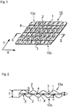
- a cleaning sheet 10 is composed of a fiber aggregate 1 made by water needling of a fibrous web, and a net-form sheet 4 disposed in the fiber aggregate 1.
- the constituent fibers of the fiber aggregate 1 and the net-form sheet 4 are entangled through water needling, and thereby the fiber aggregate 1 and the net-form sheet 4 are integrated together, as will be described in detail further below.
- the cleaning sheet 10 has a first side 10a and a second side 10b, and also has a multitude of projections 2, 2 formed to protrude from one side toward the other. Between adjacent projections 2, 2 are formed respective depressions 3, 3, thereby rendering projecting-and-depressed shapes to the entire sheet.
- the projections 2, 2 all have substantially the same size and are shaped like rather elongated, narrow mountains provided at regular intervals.
- the interval between adjacent projections 2, 2 is preferably 1 to 10 mm, more preferably 1 to 7 mm, in the sheet's width direction (X direction in Fig. 1 ; the cross direction (CD) in the present embodiment), and is preferably 4 to 20 mm, more preferably 4 to 15 mm, in the sheet's length direction (Y direction in Fig. 1 ; the machine direction (MD) in the present embodiment).
- Some of the projections 2 may be connected in the sheet's width direction and/or length direction to form a continuous projection.
- Providing the projections 2 at the above-described intervals can make the feel of the sheet 10 favorable to the touch, achieve excellent dirt cleaning properties with respect to grooves of wooden floors and uneven surfaces, and also achieve excellent capabilities of trapping and retaining relatively large dirt such as bread crumbs.
- both sides of the cleaning sheet 10 have similar properties/capabilities, and the shapes and intervals of the projections 2 on the second side 10b are preferably substantially the same as those of the first side 10a.
- the total area of the projections 2 on the second side 10b is preferably 20 to 100%, more preferably 35 to 100%, with respect to the total area of the projections 2 on the first side 10a.
- the projections 2 on the first side of the cleaning sheet 10 are in an inside-outside relationship with the depressions 3 in the second side of the sheet 10, and the projection 2 preferably has the inverted shape of the depression 3.
- the projections 2 and the depressions 3 consist of the fiber aggregate 1 and are formed by merely entangling the constituent fibers of the fiber aggregate 1.
- the projections 2 and the depressions 3 are pleasant to the touch and have excellent capabilities of trapping and retaining dirt such as strands of hair and small particles of dust, in contract to projections formed by fusion-bonding caused by partially heating and pressurizing fibers consisting of thermoplastic resin through embossing etc.
- the projections 2 and the depressions 3 of the cleaning sheet 10 are formed by rearranging and re-entangling the constituent fibers of the fiber aggregate 1 which is caused by the water needling process applied thereto; thus, the projections 2 and the depressions 3 can retain their shapes by themselves. Accordingly, the projections 2 and the depressions 3 are less prone to collapse due to load. Owing to the existence of the projections 2 and depressions 3, the apparent thickness of the cleaning sheet 10 becomes larger than the thickness of the fiber aggregate 1 before being provided with the projections 2 and depressions 3.
- the cleaning sheet 10, with its projections 2 and depressions 3 having good shape-retainability, has excellent properties of cleaning grooves and uneven surfaces as well as excellent capabilities to trap and retain dirt such as bread crumbs.
- the projections 2 and depressions 3 retain their shapes even when loaded and that the amount of change in thickness is 1 mm or less, more preferably 0.8 mm or less.
- the expression "form by rearranging and re-entangling fibers” means that a fiber aggregate, which has once been weakly entangled together through water needling, is again subjected to water needling, this time on a patterning member having a multitude of projecting-and-depressed sections or a multitude of openings, such that the fibers are rearranged along the projecting-and-depressed sections and then entangled again.
- the projections 2 and depressions 3 are formed by rendering a zigzag form to the fiber aggregate 1 in its thickness direction.
- the multitude of bent sections formed in the zigzag fiber aggregate 1 correspond to the respective projections 2 and depressions 3.
- the projections 2 and depressions 3 are formed by rearrangement of the fibers; in doing so, distribution of fibers, which is caused by the high-pressure water pressing the constituent fibers of the projections 2 so that they drift toward the depressions 3, is kept extremely small. Note that distributing the fibers to a greater extent will result in holes being formed in positions where the projections 2 should have existed.
- the cleaning sheet 10 structured as above has largely projecting-and-depressed shapes despite its low basis weight.
- the zigzags of the fiber aggregate 1 may be formed either along the machine direction (MD) or the width direction (cross direction; CD).
- the fiber aggregate 1 can be rendered the zigzag form, without giving rise to distribution of fibers, simply by, for example, setting the energy applied during the water needling process to the values described further below.
- the bending ratio is as high as 2 to 15%, more preferably 3 to 15%. Note that the "bending ratio" is measured according to the procedure described on column 12, line 51 through column 13, line 6 of US 6,936,333 .
- projections 2 there are, on average, 50 to 850, more preferably 100 to 600, of projections 2 per a 10-by-10-centimeter area on one side of the cleaning sheet 10 at any location of that side. Keeping the number of projections 2 within the above-described range allows the projections 2 and depressions 3 to be arranged in good balance, thus achieving even better capabilities of trapping and retaining small particles of dirt and also even better capabilities of trapping and retaining relatively-large dirt such as bread crumbs.
- the apparent specific volume of the cleaning sheet 10 is preferably 23 to 100 cm 3 /g, more preferably 25 to 90 cm 3 /g, and even more preferably 30 to 80 cm 3 /g.
- An apparent specific volume of 23 cm 3 /g or above allows the sheet to sufficiently conform to grooves and uneven surfaces and trap dirt. Further, an apparent specific volume of 100 cm 3 /g or less makes the inter-fiber distance appropriate, thus allowing the sheet to retain dirt securely.
- the value of the apparent specific volume is defined as a quotient found by dividing the value of the apparent thickness (described later) by the basis weight of the fiber aggregate (for a sheet entangled and integrated with a net-form sheet, the basis weight excluding the net-form sheet).
- the cleaning sheet 10 has an apparent specific volume under load during cleaning of 18 cm 2 /g or above, and more preferably 20 cm 2 /g or above, with a maximum of 100 cm 2 /g.
- the cleaning sheet 10 has an apparent thickness T (thickness between the uppermost section of the first side 10a and the lowermost section of the second side 10b) that is thicker than the thickness t of the fiber aggregate 1 itself, and is thus extremely bulky.
- the value of the apparent thickness T of the cleaning sheet 10 is preferably 1 to 5 mm, and more preferably 1.4 to 4 mm, from the standpoint of forming enough voids in the sheet to make the sheet bulky and allowing the sheet to be suitably used as a cleaning sheet, for example.
- the value of the thickness t of the fiber aggregate 1 itself is determined depending on the basis weight and processing conditions of the fiber aggregate 1, and is preferably 0.5 to 4 mm, more preferably 1 to 3 mm.
- the height h of the projection as illustrated in Fig. 2 is preferably 0.2 mm to 4 mm, more preferably 0.5 mm to 4 mm.
- the elongation of the cleaning sheet 10 in its machine direction (MD) is preferably 5% or less, and more preferably 4% or less, under the condition that a load of 5 N is applied to a 30-mm-wide sample.
- MD machine direction
- Such an elongation is preferable in terms of preventing deformation of the projections 2 and depressions 3 caused by pulling and stretching of the cleaning sheet 10 during production or during use of the cleaning sheet 10, to thus prevent reduction in bulkiness of the cleaning sheet 10.
- the "elongation" in the machine direction is measured as follows. A sample 30-mm wide in a direction orthogonal to the machine direction is cut out from the cleaning sheet 10. The sample is then held in a tensile tester at a chuck-to-chuck distance of 100 mm, and the sample is pulled in the machine direction at a speed of 300 mm/min. The "elongation” is found by dividing the sample's elongation amount at a tensile load of 5 N by the initial sample length (100 mm) and multiplying the quotient by 100.
- the fiber aggregate 1 is a nonwoven-like article formed by entangling the constituent fibers of a fibrous web together by applying water needling thereto.
- the fiber aggregate 1 is formed by merely entangling its constituent fibers, and therefore, the degree of freedom of the constituent fibers is high compared to a web made by simply fusing or bonding the constituent fibers.
- the fiber aggregate 1 has excellent capabilities to trap and retain dirt, such as strands of hair and small particles of dust, with its constituent fibers, and also has a pleasant feel to the touch.
- the fibers that are used to constitute the fiber aggregate 1 consist only of PET in order to effectively make the cleaning sheet 10 bulky through the hot-air processing.
- the PET has a weight-average molecular weight of 5,000 to 100,000, more preferably 8,000 to 50,000, from the standpoint of rendering the cleaning sheet 10 bulky through hot-air processing.
- the fiber aggregate 1 consists only of the fibers containing PET in order to effectively make the cleaning sheet 10 bulky through the hot-air processing.
- the thickness of the fiber containing PET is not particularly critical in terms of the bulkiness of the cleaning sheet 10 rendered by the hot-air processing. From the standpoint of the capabilities to trap and retain strands of hair and dirt, the thickness of the fiber containing PET is preferably 0.05 to 100 dtex, more preferably 0.5 to 20 dtex.
- the cleaning sheet 10 has a net-form sheet 4 disposed in the fiber aggregate 1, as described above.
- the net-form sheet 4 is a resinous net shaped like a grid as a whole.
- the net-form sheet 4 preferably has an air permeance of 0.1 to 1000 cm 3 /(cm 2 ⁇ sec). Materials other than a net, such as a nonwoven fabric, paper, or a film, may be used as the net-form sheet 4 as long as the air permeance is within the above-described range.
- the constituent fibers of the fiber aggregate 1 entangled together, but also the constituent fibers of the fiber aggregate 1 are entangled with the net-form sheet 4, thus improving the tensile strength.
- the thread diameter of the net-form sheet 4 is preferably 50 to 600 ⁇ m, more preferably 100 to 400 ⁇ m.
- the distance between adjacent threads is preferably 2 to 30 mm, more preferably 4 to 20 mm.
- Materials usable as the constituent material of the net-form sheet 4 are described, for example, on column 3, lines 39 to 46 of US 5,525,397 .
- the constituent material of the net-form sheet 4 may be heat-shrinkable. By applying heat processing at the time of producing cleaning sheets, heat-shrinkable materials can provide cleaning sheets having increased apparent thickness T and sharply-shaped projections. It is, however, preferable that the net-form sheet 4 is not heat-shrunk, or in cases where it is heat-shrunk, the heat-shrinkage rate after being heated for 3 minutes at 140°C is preferably 3% or less.
- the basis weight of the cleaning sheet 10 is preferably 30 to 110 g/m 2 , more preferably 38 to 80 g/m 2 , and even more preferably 45 to 80 g/m 2 , in terms of providing a suitable thickness to the sheet and improving processability.
- the breaking strength for a 30-mm-wide sample is preferably 5 N or above, more preferably 7 N or above, from the standpoint of providing a sheet strong enough to endure use.
- the breaking strength need only be within the above-described range in at least one direction of the cleaning sheet 10; preferably, the breaking strength is within the above-described range in the width direction (cross direction; CD) which is most difficult to make strong.
- the maximum breaking strength is around 20 N in terms of practical use.
- the breaking strength is measured as follows. A sample 30-mm wide in a direction orthogonal to the sheet's fiber-orientation direction is cut out. The sample is then held in a tensile tester at a chuck-to-chuck distance of 100 mm, and the sample is pulled in the direction orthogonal to the fiber-orientation direction at a speed of 300 mm/min. The load value at which the sheet starts to tear (the first peak value appearing in the continuous curve obtained through this measurement) is taken as the "breaking strength".
- the process for producing the cleaning sheet 10 of the present embodiment includes, in the following order: a superposing step of superposing an upper-layer fibrous web 1a and a lower-layer fibrous web 1b on the respective sides of a net-form sheet 4; an entangling step of entangling, through water needling, the constituent fibers of the fibrous webs 1a and 1b together to form a fiber aggregate, and also entangling the constituent fibers of the fibrous webs 1a and 1b and the net-form sheet 4 together to form a laminate 6 in which the fibrous webs and the net-form sheet have been integrated; and a projection-and-depression applying step of carrying the laminate 6 onto a patterning member having a multitude of projecting-and-depressed sections and making some portions of the fiber aggregate protrude into the depressed sections, so as to form a multitude of projections corresponding to the depressed sections.
- Fig. 3 illustrates a production device 20 preferably used for the process of producing the cleaning sheet 10.
- the production device 20 can roughly be divided into a superposing section 20A, an entangling section 20B, and a projection-and-depression applying section 20C.
- the superposing section 20A includes: carding machines 21A and 21B for respectively producing the fibrous webs la and 1b; paying-out rolls 22, 22 for paying out the fibrous webs la and 1b; and a roll 24 for paying out the net-form sheet.
- the entangling section 20B includes a web-supporting belt 25 consisting of an endless belt; and first water-jet nozzles 26.
- the projection-and-depression applying section 20C includes: a patterning member 27 consisting of an endless belt; and second water-jet nozzles 28.
- the patterning member 27 rotates in the direction illustrated by the arrows in Fig. 3 .
- the patterning member 27 is liquid-permeable and has a multitude of projecting-and-depressed sections on its surface. Details thereof are described on column 8, line 23 through column 9, line 19 and Figs. 4(a) and (b) of US 6,936,333 . After the projection-and-depression applying section 20C comes a carrying belt 29.
- the patterning member 27 has some degree of thickness, and more specifically, the thickness is preferably 5 to 25 mm, more preferably 5 to 15 mm, in terms of applying a sufficiently large bulkiness and in terms of energy efficiency at the time of applying the projections and depressions.
- the air permeance of the patterning member 27 is preferably 800 to 3000 cm 3 /(cm 2 ⁇ sec), more preferably 800 to 2000 cm 3 /(cm 2 ⁇ sec).
- the carding machines 21A and 21B in the superposing section 20A respectively pay out the fibrous webs la and 1b continuously via the paying-out rolls 22, 22.
- at least one of the fibrous webs la and 1b contains 40% by weight or more of fibers containing polyethylene terephthalate.
- a roll 23 of net-form sheet 4 is disposed between the carding machines 21A and 21B, and the paying-out roll 24 for the roll 23 pays out the net-form sheet 4.
- the fibrous webs la and 1b are superposed on the respective sides of the net-form sheet 4, to form a superposed element 5.
- At least one of the fibrous webs 1a and 1b contains 40% by weight or more of fibers containing PET. More preferably, both the fibrous webs 1a and 1b contain 40% by weight or more of fibers containing PET, and even more preferably, both the fibrous webs 1a and 1b consist of 100% of fibers containing PET.
- the superposed element 5 transported and carried on the web-supporting belt 25 is subjected to entangling processing by high-pressure jet streams of water emitted from the first water-jet nozzles 26.
- the constituent fibers of the fibrous webs 1a and 1b in the superposed element 5 are entangled together to form a fiber aggregate, and also, the constituent fibers and the net-form sheet 4 are entangled together, to form a laminate 6 in which the fibrous webs and the net-form sheet have been integrated together.
- the fibers constituting the fiber aggregate in the laminate 6 have a low degree of entanglement.
- the degree of entanglement is preferably 0.05 to 2 N ⁇ m/g, more preferably 0.2 to 1.2 N ⁇ m/g. Controlling the degree of entanglement of the fibers constituting the fiber aggregate in the laminate to fall within the above-described range allows production of a cleaning sheet having clear projecting-and-depressed shapes, without giving rise to any holes, at the time of applying projections and depressions in the projection-and-depression applying section 20C described below.
- the "entanglement coefficient” is a measure indicating the degree of entanglement among constituent fibers, and is represented by the initial gradient of the stress-strain curve measured in a direction perpendicular to the fiber orientation direction of the fiber aggregate 1 of the integrated laminate 6; the smaller the coefficient, the weaker the entanglement among the fibers.
- the "fiber orientation” is in the direction in which the maximum point-load value in a tensile-strength test becomes the largest;
- the "stress” is the quotient found by dividing the tensile load buy the "clamping width" (width of the specimen in the tensile-strength test) and by the basis weight of the fiber aggregate 1; and the “strain” refers to the elongation amount.
- a concrete example for measuring the entanglement coefficient is described on column 12, lines 32 to 50 of US 6,936,333 B .
- the laminate 6 is transported onto the patterning member 27 and carried thereby. While being carried, the laminate 6 is partially pressurized by high-pressure jet streams of water emitted from the second water-jet nozzles 28. At this time, portions of the laminate 6 that are located on the depressed sections of the patterning member 27 are pressurized, and the pressurized portions thus protrude into the depressed sections. As a result, the pressurized portions are formed into depressions 3 corresponding to the depressed sections. On the other hand, portions of the laminate 6 that are located on the projecting sections of the patterning member 27 are not made to protrude, and thus become the projections 2.
- the projections 2 are determined depending on such factors as the type of the patterning member 27 and the entangling energy applied to the fiber aggregate by the high-pressure jet streams of water in the entangling section 20B and the projection-and-depression applying section 20C.
- the entangling energy in turn, can be controlled according to such conditions as the nozzle shape of the water-jet nozzles, the nozzle pitch, water pressure, number of stages (pieces) of nozzles, and line speed.
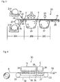
- the laminate 6 provided with the projecting-and-depressed shapes is then carried to a hot-air processing device 30 illustrated in Fig. 4 .
- the laminate 6 may once be wound into a roll, and then the laminate 6 may be unwound from the roll to be carried into the hot-air processing device 30.
- the laminate 6 produced by the device 20 illustrated in Fig. 3 may be directly carried into the hot-air processing device 30, without being wound into a roll. It is, however, preferable to once wind the laminate 6 into a roll and then pay it out from the roll to undergo hot-air processing, because the bulkiness -restoring effect becomes more significant.
- the laminate 6 provided with the projecting-and-depressed shapes is subjected to drying by such means as hot air, regardless of whether it is once wound into a roll or not.
- the drying process is applied to the sheet manufactured through water needling by employing commonly-used devices and conditions (omitted from drawings).
- the drying temperature is below the melting point of the component having the lowest melting point among the constituent fibers of the laminate 6.
- the device 30 illustrated in Fig. 4 includes: a wire-mesh conveyer belt 32; a heating zone H; and a cooling zone C.
- the conveyer belt 32 is an endless belt supported by a pair of support shafts 33, 33 and rotating in a predetermined direction.
- the heating zone H is provided on the upstream side relative to the rotating direction of the conveyer belt 32, whereas the cooling zone C is provided on the downstream side relative thereto.
- the conveyer belt 32 is made of metal and/or a resin such as polyethylene terephthalate.
- the conveyer belt 32 is made of a resin such as polyethylene terephthalate from the standpoint of heat-radiation efficiency in the heating zone H and the cooling zone C.
- a first blower 34 is disposed above and in opposition to the conveyer belt 32.
- the first blower 34 blows, toward the conveyer belt 32, hot air heated to a predetermined temperature.
- a first suction box 35 is disposed in opposition to the first blower 34 across the conveyer belt 32, for suction of the hot air blown from the first blower 34.
- the first blower 34 and the first suction box 35 constitute the heating zone H.
- the hot air sucked in by the first suction box 35 is fed into the first blower 34 through a duct (not shown). In other words, the hot air circulates between the first blower 34 and the first suction box 35.
- a second blower 36 is disposed in opposition to the conveyer belt 32 and immediately downstream of the first blower 34 relative to the rotating direction of the conveyer belt 32.
- the second blower 36 blows, toward the conveyer belt 32, cool air at a predetermined temperature.
- a second suction box 37 is disposed in opposition to the second blower 36 across the conveyer belt 32, for suction of the cool air blown from the second blower 36.
- the second blower 36 and the second suction box 37 constitute the cooling zone C.
- the cool air sucked by the second suction box 37 is discharged outside the device through a duct (not shown). In other words, in contrast to the hot air in the heating zone H, the cool air is not circulated between the second blower 36 and the second suction box 37. This is done in order to prevent heating of the cool air due to circulation and increase the efficiency for cooling the laminate 6.
- Partitioning plates 38, 38 are disposed between the first blower 34 and the second blower 36 and between the first suction box 35 and the second suction box 37, respectively.
- the partitioning plates 38 prevent the hot air and the cool air from mixing together.
- a rolled-up laminate 6 produced by the device 20 illustrated in Fig. 3 is arranged upstream of the first blower 34 of the device 30, and the laminate 6 is paid out from the roll. Because the laminate 6 is wrapped into a roll, its bulkiness is reduced due to the roll-up pressure. The bulkiness of this rolled-up laminate 6 is restored by passing it through the device 30.
- the laminate 6 is carried along with the conveyer belt 32, and the carried laminate 6 is sent into the heating zone H, where the first blower 34 blows, toward the conveyer belt 32, hot air heated to a predetermined temperature.
- the hot air is blown to the laminate 6 by through-air technique. That is, the hot air is blown to the laminate 6 and then passes through the laminate 6.
- this hot-air blowing operation serves to increase the bulkiness of the laminate 6, which is in a bulkiness -reduced state, and to restore its bulkiness back to the same degree as before roll-up.
- the presence of the net-form sheet 4 in the laminate 6 significantly heightens the degree of increase in bulkiness.
- the hot air to be blown to the laminate 6 should be adjusted to a temperature above the glass transition temperature (Tg (°C)) of PET in the PET-containing fibers of the laminate and below "Tg (°C) + 70°C". In cases where the temperature of the hot air is equal to or below Tg (°C), the effect of blowing the hot air will not be achieved sufficiently and the bulkiness of the laminate 6 will not be restored. On the other hand, blowing hot air at temperatures equal to or above "Tg (°C) + 70°C" will cause the fibers to melt, and thus in this case also, the bulkiness of the laminate 6 will not be restored.
- Tg (°C) glass transition temperature
- the temperature of the hot air is preferable equal to or above 80°C and equal to or below 140°C, and more preferably equal to or above 85°C and equal to or below 135°C. It is also preferable that the temperature of the hot air to be blown is below the melting point of the resin constituting the net-form sheet 4.
- Tg glass transition temperature
- DSC differential scanning calorimeter
- the time for which the hot air is blowen is not a critical element in terms of bulkiness restoring, and a short period of time will be sufficient. More specifically, the bulkiness of the laminate 6 will be restored in an extremely short hot-air-blowing time as short as preferably 0.05 to 3 seconds, more preferably 0.05 to 1 second, and even more preferably 0.05 to 0.5 seconds. This contributes to an improvement in production efficiency and downsizing of the device 30. It is thought that through-air technique contributes greatly to the short blowing time. Constant-temperature drying ovens and driers may be considered as other usable means for applying heat to the laminate 6 besides blowing hot air by through-air technique, but these blowing methods cannot achieve bulkiness restoration in such a short time.
- the speed at which to blow the hot air is preferably 0.5 to 10 m/sec, more preferably 1 to 5 m/sec, in terms of hot-air cost and downsizing of the device, although the speed depends on the temperature of the hot air, the basis weight of the laminate 6, and the carrying speed.
- the above-described operation restores the bulkiness of the laminate 6 to around 1.2 to 3 times the bulkiness before blowing hot air (i.e., the bulkiness before blowing hot air becomes 1/1.2 to 1/3 of the bulkiness after blowing hot air), thus achieving the intended cleaning sheet.
- the thickness of the laminate 6 is restored to around 50 to 100% of the thickness before being wound around a roll.
- the present Inventors have found through investigation that rolling-up the cleaning sheet 10, whose bulkiness has been restored by blowing hot air, may again reduce the restored bulkiness of the cleaning sheet 10.
- the Inventors also found that, to prevent this, it is effective to blow cool air onto the cleaning sheet 10 by through-air technique immediately after the bulkiness of the cleaning sheet 10 has been restored by blowing hot air. Blowing cool air cools the bulky cleaning sheet 10 so that its bulkiness is sustained, and this prevents the bulkiness from being reduced even when the sheet is wound into a roll shape.
- the cooling zone C is disposed adjacent to and immediately downstream of the heating zone H in the carrying direction of the cleaning sheet 10.
- blow cool air onto the cleaning sheet 10 immediately after the bulkiness of the cleaning sheet 10 has been restored by blowing hot air means that there is no operation between the step of blowing hot air onto the cleaning sheet 10 and the subsequent step of blowing cool air, and does not intend to mean that there is no time difference between the hot-air blowing and cool-air blowing.
- cool air at a predetermined temperature is blown from the second blower 36 toward the conveyer belt 32.
- the cool air is blown by through-air technique onto the cleaning sheet 10 in the cooling zone C.
- the cool air is blown onto the cleaning sheet 10 and then passes through the cleaning sheet 10.
- a sufficient cooling effect can be achieved at a cool-air temperature of 50°C or below, more preferably 30°C or below, although this may depend on the type of fiber constituting the nonwoven fabric.
- a cool-air temperature of 50°C or below, more preferably 30°C or below, although this may depend on the type of fiber constituting the nonwoven fabric.
- cool-air temperature There is no particular lower limit to the cool-air temperature, but room temperature around 20 to 25°C is suitable in terms of energy cost and simplification of the device 30.
- the speed at which to blow the cool air is preferably 1 to 10 m/sec, more preferably 1 to 5 m/sec, and even more preferably 1 to 3 m/sec, from the standpoint of sufficiently cooling the cleaning sheet 10 which is hot due to blowing of hot air.
- a wind speed within the above-described range will achieve a sufficient cooling effect. It is also possible to reduce the possibility of inhibiting stable carrying of the cleaning sheet 10 due to high wind speed.
- the cleaning sheet 10 will be sufficiently cooled in an extremely short cool-air-blowing time as short as 0.01 second or longer, more preferably 0.02 to 1 second, and even more preferably 0.05 to 0.5 seconds. It is thought that through-air technique contributes greatly to the short blowing time.
- the sheet 10 may shrink due to the hot air blown thereon in the heating zone H.
- Shrinking is prone to occur particularly in the width direction of the sheet 10, i.e., in the direction orthogonal to the carrying direction of the sheet 10.
- it is preferable to suppress the sheet from shrinking in its width direction such that the width of the cleaning sheet 10 after blowing cool air (i.e., the width of the cleaning sheet 10 after leaving the cooling zone C) is 95% or above, more preferably 97% or above, with respect to the width of the laminate 6 before blowing hot air thereon (i.e., the width of the laminate 6 before entering the heating zone H).
- One way to suppress shrinking is to grip both sides of the laminate 6 along the carrying direction with predetermined gripping means so that the width of the laminate 6 will not change, and send the laminate 6 into the heating zone H and the cooling zone C in this gripped state.
- Another very simple way may be to adjust the wind speed of the hot air and cool air so as to press the laminate 6 against the conveyer belt 32 at the time of blowing the hot air and cool air onto the laminate 6 respectively in the heating zone H and the cooling zone C, and carry the laminate 6 in such a state that its width does not change.
- the range of the wind speed of the hot air and cool air is as described above; the wind speed may be determined within the above-described range depending on the basis weight of the laminate 6 and the carrying speed.
- the cleaning sheet 10 By undergoing the above operations, the cleaning sheet 10 becomes very bulky.
- the bulky cleaning sheet 10 then undergoes various subsequent processing steps. Examples of such processing steps include a step of cutting the cleaning sheet 10 into a multitude of individual sheets, a step of placing several pieces of the cut-up cleaning sheets 10 on top of one another and putting them in a packing bag, and so forth.
- the cleaning sheets 10 obtained may be used as dry cleaning sheets, or as wet cleaning sheets impregnated with various cleaning agents.
- the present invention has been described in detail above according to a preferred embodiment thereof.
- fibrous webs 1a and 1b were disposed on respective sides of the net-form sheet 4; instead a fibrous web may be disposed only on one side of the net-form sheet 4.
- the fibrous web preferably contains 40% by weight or more of fibers containing polyethylene terephthalate.
- the hot-air processing using the device 30 was followed by cool-air processing; however, the cool-air processing is not always necessary.
- PET fiber (1.45 dtex; 38 mm; Tg: 78°C; weight-average molecular weight: 20,000) was employed as the starting material and was made into a fibrous web having a basis weight of 24 g/m 2 by an ordinary carding method.
- a polypropylene grid-shaped net (inter-fiber distance: 8 mm; thread diameter: 300 ⁇ m) was used as the net-form sheet.
- the above-described fibrous webs were superposed on respective sides of the net-form sheet. Then, the fibrous webs and the net-form sheet were entangled and integrated together by jet streams of water emitted from the plurality of nozzles illustrated in Fig.
- the applied energy Em was 295 kJ/kg.
- the laminate was subjected to jet streams of water emitted from a plurality of nozzles under water-pressure conditions of 1 to 5 MPa on a patterning member, so as to provide the laminate with projecting shapes.
- the shaped laminate was then dried with hot air, to thus obtain a laminate having projecting-and-depressed shapes, as illustrated in Figs. 1 and 2 .
- the applied energy Ef was 175 kJ/kg.
- the patterning member used was structured as described in Figs. 4(a) and (b) of US 6,936,333 B2 .
- the thus-obtained laminate was once wound into a roll. Then, the laminate was unwound from the roll and carried to the device 30 illustrated in Fig. 4 .
- the pay-out speed was 150 m/min, a speed suitable for high-speed production.
- Hot air at the temperature shown in Table 1 was blown onto the laminate at a wind speed of 3 m/sec by through-air technique. After the hot-air blowing process, the laminate was subjected to natural cooling. In this way, a cleaning sheet was prepared.
- Respective cleaning sheets were prepared in the same way as in Example 1, except that the respective conditions shown in Table 1 were employed for the hot-air processing.
- a cleaning sheet was prepared in the same way as in Example 1, except that a fibrous web having a basis weight of 27 g/m 2 was used, and no hot-air processing was conducted.
- Each cleaning sheet was attached to the head of a "Quickie Wiper" (registered trademark), a cleaning tool manufactured by Kao Corporation.
- the trapping rate for when the side of the cleaning sheet onto which the jet streams of water were blown during production (referred to hereinafter as “back side") was used as the cleaning surface and also the trapping rate for when the side opposite from the side onto which the jet streams of water were blown (referred to hereinafter as "front side") were measured.
- a 30-by-60-centimeter wooden floor (“Woody Tile MT613T”; product of Matsushita Electric Works Co., Ltd.) was used as a "normal wooden-floor surface”. Ten pieces of hair, each approximately 10 cm long, were scattered on this "normal surface”.
- the cleaning sheet was then placed thereon and moved back-and-forth 5 times at a given stroke (60 cm), and the number of pieces of hair trapped on the cleaning sheet was counted. This operation was repeated 3 times consecutively, and the number of pieces of trapped hair, among the 30 pieces of scattered hair, was counted. The quotient found by dividing the number of pieces of trapped hair by 30 was multiplied by 100, to find the "hair trapping rate (%)".
- a 30-by-60-centimeter smooth-finish decorative board was used as a low-friction "smooth surface"; 10 pieces of hair, each approximately 10 cm long, were scattered on this "smooth surface”; the cleaning sheet was then placed thereon and moved back-and-forth twice at a given stroke (60 cm); the number of pieces of hair trapped on the cleaning sheet was counted; and thereafter, the same steps as those for the "normal surface” were performed, to find the "trapping rate".
- the thicknesses at a load of 300 Pa and 700 Pa were measured, respectively.
- the sheet's cross-section in its thickness direction was observed with a microscope, to visually evaluate the clarity of the projecting-and-depressed shapes according to the following criteria:
Landscapes
- Engineering & Computer Science (AREA)
- Textile Engineering (AREA)
- Mechanical Engineering (AREA)
- Chemical & Material Sciences (AREA)
- Chemical Kinetics & Catalysis (AREA)
- Nonwoven Fabrics (AREA)
- Cleaning Implements For Floors, Carpets, Furniture, Walls, And The Like (AREA)
- Laminated Bodies (AREA)
Applications Claiming Priority (2)
| Application Number | Priority Date | Filing Date | Title |
|---|---|---|---|
| JP2008137435 | 2008-05-27 | ||
| PCT/JP2009/059536 WO2009145148A1 (ja) | 2008-05-27 | 2009-05-25 | 清掃用シートの製造方法 |
Publications (3)
| Publication Number | Publication Date |
|---|---|
| EP2286705A1 EP2286705A1 (en) | 2011-02-23 |
| EP2286705A4 EP2286705A4 (en) | 2011-09-14 |
| EP2286705B1 true EP2286705B1 (en) | 2017-07-26 |
Family
ID=41377021
Family Applications (1)
| Application Number | Title | Priority Date | Filing Date |
|---|---|---|---|
| EP09754656.8A Not-in-force EP2286705B1 (en) | 2008-05-27 | 2009-05-25 | Process for producing cleaning sheet |
Country Status (6)
| Country | Link |
|---|---|
| US (1) | US8650727B2 (ja) |
| EP (1) | EP2286705B1 (ja) |
| JP (1) | JP5255517B2 (ja) |
| CN (1) | CN102036595A (ja) |
| MY (1) | MY150983A (ja) |
| WO (1) | WO2009145148A1 (ja) |
Families Citing this family (14)
| Publication number | Priority date | Publication date | Assignee | Title |
|---|---|---|---|---|
| WO2010047292A1 (ja) * | 2008-10-20 | 2010-04-29 | ユニ・チャーム株式会社 | 不織布の厚さを増加させる方法およびそのための装置 |
| JP5477123B2 (ja) * | 2010-04-02 | 2014-04-23 | Jnc株式会社 | 熱風処理不織布加工装置および加工方法 |
| JP5629525B2 (ja) * | 2010-08-06 | 2014-11-19 | 花王株式会社 | 不織布の嵩増加装置 |
| JP5752077B2 (ja) * | 2012-03-30 | 2015-07-22 | ユニ・チャーム株式会社 | 不織布および不織布の製造方法 |
| JP5777558B2 (ja) * | 2012-04-20 | 2015-09-09 | ユニ・チャーム株式会社 | 不織布の嵩を回復させる方法及び装置 |
| JP5840100B2 (ja) * | 2012-09-28 | 2016-01-06 | ユニ・チャーム株式会社 | 不織布 |
| JP6126398B2 (ja) | 2013-02-07 | 2017-05-10 | ユニ・チャーム株式会社 | 清掃具 |
| JP6208949B2 (ja) | 2013-02-07 | 2017-10-04 | ユニ・チャーム株式会社 | 清掃具 |
| JP5832477B2 (ja) * | 2013-05-31 | 2015-12-16 | ユニ・チャーム株式会社 | 不織布の嵩回復方法 |
| JP6126968B2 (ja) * | 2013-10-18 | 2017-05-10 | ユニ・チャーム株式会社 | 不織布の嵩回復装置、及び嵩回復方法 |
| JP7055009B2 (ja) * | 2017-12-06 | 2022-04-15 | 花王株式会社 | ワイピングシート及び清掃具 |
| CN108842308B (zh) * | 2018-05-24 | 2020-06-12 | 任丘市奥东新型建材有限公司 | 长丝或短丝加筋聚酯毡基布及其制备方法 |
| CN109338593A (zh) * | 2018-10-08 | 2019-02-15 | 滁州辉煌无纺科技有限公司 | 一种高宽度sms级纺熔无纺布成型设备 |
| CN110154491A (zh) * | 2019-06-04 | 2019-08-23 | 杭州千千达科技有限公司 | 一次性复合毛巾材料的生产装置及其工艺 |
Family Cites Families (17)
| Publication number | Priority date | Publication date | Assignee | Title |
|---|---|---|---|---|
| US5143779A (en) * | 1988-12-23 | 1992-09-01 | Fiberweb North America, Inc. | Rebulkable nonwoven fabric |
| US5368925A (en) * | 1989-06-20 | 1994-11-29 | Japan Vilene Company, Ltd. | Bulk recoverable nonwoven fabric, process for producing the same and method for recovering the bulk thereof |
| JP3096094B2 (ja) | 1991-07-11 | 2000-10-10 | 花王株式会社 | 嵩高性シート及びその製造方法 |
| JP3313786B2 (ja) | 1991-11-13 | 2002-08-12 | 花王株式会社 | 湿式清掃用シート及びその製造方法 |
| US5334446A (en) * | 1992-01-24 | 1994-08-02 | Fiberweb North America, Inc. | Composite elastic nonwoven fabric |
| JP2765690B2 (ja) * | 1993-12-27 | 1998-06-18 | 花王株式会社 | 清掃用シート |
| EP0796940B1 (en) * | 1995-10-06 | 2003-02-26 | Nippon Petrochemicals Co., Ltd. | Water jet intertwined nonwoven cloth and method of manufacturing the same |
| JP3657700B2 (ja) * | 1996-06-18 | 2005-06-08 | 新日本石油化学株式会社 | カサ高性不織布の製造方法 |
| KR100730880B1 (ko) | 2000-03-24 | 2007-06-20 | 가오가부시끼가이샤 | 벌키 시트 및 이의 제조방법 |
| JP2003230519A (ja) * | 2002-02-07 | 2003-08-19 | Crecia Corp | 床用清掃シート |
| US6739023B2 (en) * | 2002-07-18 | 2004-05-25 | Kimberly Clark Worldwide, Inc. | Method of forming a nonwoven composite fabric and fabric produced thereof |
| JP3983202B2 (ja) * | 2003-06-24 | 2007-09-26 | 花王株式会社 | 不織布の嵩回復方法 |
| CN100371513C (zh) | 2002-09-25 | 2008-02-27 | 花王株式会社 | 无纺布的膨松恢复方法 |
| JP4030484B2 (ja) | 2002-09-25 | 2008-01-09 | 花王株式会社 | 不織布の嵩回復方法 |
| JP2007312931A (ja) * | 2006-05-24 | 2007-12-06 | Daiwabo Co Ltd | ワイパー |
| JP5069891B2 (ja) * | 2006-06-23 | 2012-11-07 | ユニ・チャーム株式会社 | 不織布 |
| JP5328088B2 (ja) * | 2006-06-23 | 2013-10-30 | ユニ・チャーム株式会社 | 不織布 |
-
2009
- 2009-05-25 JP JP2009125404A patent/JP5255517B2/ja active Active
- 2009-05-25 CN CN2009801180691A patent/CN102036595A/zh active Pending
- 2009-05-25 MY MYPI20105146 patent/MY150983A/en unknown
- 2009-05-25 EP EP09754656.8A patent/EP2286705B1/en not_active Not-in-force
- 2009-05-25 US US12/992,559 patent/US8650727B2/en not_active Expired - Fee Related
- 2009-05-25 WO PCT/JP2009/059536 patent/WO2009145148A1/ja active Application Filing
Non-Patent Citations (1)
| Title |
|---|
| None * |
Also Published As
| Publication number | Publication date |
|---|---|
| US8650727B2 (en) | 2014-02-18 |
| JP5255517B2 (ja) | 2013-08-07 |
| WO2009145148A1 (ja) | 2009-12-03 |
| CN102036595A (zh) | 2011-04-27 |
| EP2286705A4 (en) | 2011-09-14 |
| MY150983A (en) | 2014-03-31 |
| AU2009252434A1 (en) | 2009-12-03 |
| JP2010007219A (ja) | 2010-01-14 |
| US20110126388A1 (en) | 2011-06-02 |
| EP2286705A1 (en) | 2011-02-23 |
Similar Documents
| Publication | Publication Date | Title |
|---|---|---|
| EP2286705B1 (en) | Process for producing cleaning sheet | |
| EP0156234B2 (en) | Heat-resistant non-woven fabric having a high elongation at break | |
| JP3537775B2 (ja) | 嵩高シート及びその製造方法 | |
| KR100453473B1 (ko) | 드레이프및강도가개선된가는섬유배리어직물및그제조방법 | |
| JP2610408B2 (ja) | 成型性の不織シート及びその製造方法 | |
| JP2577977B2 (ja) | 伸縮性不織布及びその製造方法 | |
| US20040110442A1 (en) | Stretchable nonwoven materials with controlled retraction force and methods of making same | |
| WO1988009838A1 (en) | Lengthwise and crosswise stretchable cloth and process for its production | |
| JPH0784694B2 (ja) | 断熱性伸縮不織布およびその製造法 | |
| PL177965B1 (pl) | Sposób wytwarzania wstęgi włókniny | |
| JP4516754B2 (ja) | 高バルク複合体シートの作製方法 | |
| TWI633219B (zh) | 用於製造結構化的微絲非織造物的方法 | |
| JP4869784B2 (ja) | セルロース系不織布の製造方法 | |
| KR20110013526A (ko) | 슬릿 넥크 스펀본드 공정 및 재료 | |
| CA1075870A (en) | Process and apparatus for stretching a non-woven web of an orientable polymeric material | |
| EP1360357B1 (en) | Hydroentanglement of continuous polymer filaments | |
| JPH08291451A (ja) | 不織布およびその製造方法 | |
| JPH10127547A (ja) | 清掃用シート | |
| JPH0967748A (ja) | 嵩高性不織布およびその製造方法 | |
| JP4000424B2 (ja) | 長繊維不織布及びその製造方法 | |
| TWI573906B (zh) | 伸縮性不織布及其製造方法 | |
| JP4513838B2 (ja) | 長繊維不織布及びその製造方法 | |
| JPH0241452A (ja) | 新規な不織布およびその製造法 | |
| JPH0382862A (ja) | ポリメチルペンテン繊維からなる長繊維不織布とその製造方法 | |
| JPH0253947A (ja) | 開繊性及び可撓性に優れた繊維帯状物 |
Legal Events
| Date | Code | Title | Description |
|---|---|---|---|
| PUAI | Public reference made under article 153(3) epc to a published international application that has entered the european phase |
Free format text: ORIGINAL CODE: 0009012 |
|
| 17P | Request for examination filed |
Effective date: 20101201 |
|
| AK | Designated contracting states |
Kind code of ref document: A1 Designated state(s): AT BE BG CH CY CZ DE DK EE ES FI FR GB GR HR HU IE IS IT LI LT LU LV MC MK MT NL NO PL PT RO SE SI SK TR |
|
| AX | Request for extension of the european patent |
Extension state: AL BA RS |
|
| DAX | Request for extension of the european patent (deleted) | ||
| A4 | Supplementary search report drawn up and despatched |
Effective date: 20110812 |
|
| RIC1 | Information provided on ipc code assigned before grant |
Ipc: D04H 1/48 20060101ALI20110808BHEP Ipc: D04H 1/42 20060101ALI20110808BHEP Ipc: D04H 1/46 20060101ALI20110808BHEP Ipc: A47L 13/16 20060101AFI20110808BHEP Ipc: D04H 1/54 20060101ALI20110808BHEP Ipc: D04H 13/00 20060101ALI20110808BHEP |
|
| REG | Reference to a national code |
Ref country code: DE Ref legal event code: R079 Ref document number: 602009047367 Country of ref document: DE Free format text: PREVIOUS MAIN CLASS: A47L0013160000 Ipc: D04H0001435000 |
|
| GRAP | Despatch of communication of intention to grant a patent |
Free format text: ORIGINAL CODE: EPIDOSNIGR1 |
|
| RIC1 | Information provided on ipc code assigned before grant |
Ipc: D04H 5/03 20120101ALI20170130BHEP Ipc: D04H 5/06 20060101ALI20170130BHEP Ipc: D04H 1/498 20120101ALI20170130BHEP Ipc: A47L 13/16 20060101ALI20170130BHEP Ipc: D04H 1/482 20120101ALI20170130BHEP Ipc: D04H 1/495 20120101ALI20170130BHEP Ipc: D04H 1/54 20120101ALI20170130BHEP Ipc: D04H 1/48 20120101ALI20170130BHEP Ipc: D04H 1/492 20120101ALI20170130BHEP Ipc: D04H 1/435 20120101AFI20170130BHEP |
|
| INTG | Intention to grant announced |
Effective date: 20170308 |
|
| GRAS | Grant fee paid |
Free format text: ORIGINAL CODE: EPIDOSNIGR3 |
|
| GRAA | (expected) grant |
Free format text: ORIGINAL CODE: 0009210 |
|
| AK | Designated contracting states |
Kind code of ref document: B1 Designated state(s): AT BE BG CH CY CZ DE DK EE ES FI FR GB GR HR HU IE IS IT LI LT LU LV MC MK MT NL NO PL PT RO SE SI SK TR |
|
| REG | Reference to a national code |
Ref country code: GB Ref legal event code: FG4D |
|
| REG | Reference to a national code |
Ref country code: CH Ref legal event code: EP |
|
| REG | Reference to a national code |
Ref country code: AT Ref legal event code: REF Ref document number: 912478 Country of ref document: AT Kind code of ref document: T Effective date: 20170815 |
|
| REG | Reference to a national code |
Ref country code: IE Ref legal event code: FG4D |
|
| REG | Reference to a national code |
Ref country code: DE Ref legal event code: R096 Ref document number: 602009047367 Country of ref document: DE |
|
| REG | Reference to a national code |
Ref country code: NL Ref legal event code: MP Effective date: 20170726 |
|
| REG | Reference to a national code |
Ref country code: LT Ref legal event code: MG4D |
|
| REG | Reference to a national code |
Ref country code: AT Ref legal event code: MK05 Ref document number: 912478 Country of ref document: AT Kind code of ref document: T Effective date: 20170726 |
|
| PG25 | Lapsed in a contracting state [announced via postgrant information from national office to epo] |
Ref country code: SE Free format text: LAPSE BECAUSE OF FAILURE TO SUBMIT A TRANSLATION OF THE DESCRIPTION OR TO PAY THE FEE WITHIN THE PRESCRIBED TIME-LIMIT Effective date: 20170726 Ref country code: HR Free format text: LAPSE BECAUSE OF FAILURE TO SUBMIT A TRANSLATION OF THE DESCRIPTION OR TO PAY THE FEE WITHIN THE PRESCRIBED TIME-LIMIT Effective date: 20170726 Ref country code: NL Free format text: LAPSE BECAUSE OF FAILURE TO SUBMIT A TRANSLATION OF THE DESCRIPTION OR TO PAY THE FEE WITHIN THE PRESCRIBED TIME-LIMIT Effective date: 20170726 Ref country code: LT Free format text: LAPSE BECAUSE OF FAILURE TO SUBMIT A TRANSLATION OF THE DESCRIPTION OR TO PAY THE FEE WITHIN THE PRESCRIBED TIME-LIMIT Effective date: 20170726 Ref country code: AT Free format text: LAPSE BECAUSE OF FAILURE TO SUBMIT A TRANSLATION OF THE DESCRIPTION OR TO PAY THE FEE WITHIN THE PRESCRIBED TIME-LIMIT Effective date: 20170726 Ref country code: NO Free format text: LAPSE BECAUSE OF FAILURE TO SUBMIT A TRANSLATION OF THE DESCRIPTION OR TO PAY THE FEE WITHIN THE PRESCRIBED TIME-LIMIT Effective date: 20171026 Ref country code: FI Free format text: LAPSE BECAUSE OF FAILURE TO SUBMIT A TRANSLATION OF THE DESCRIPTION OR TO PAY THE FEE WITHIN THE PRESCRIBED TIME-LIMIT Effective date: 20170726 |
|
| PG25 | Lapsed in a contracting state [announced via postgrant information from national office to epo] |
Ref country code: LV Free format text: LAPSE BECAUSE OF FAILURE TO SUBMIT A TRANSLATION OF THE DESCRIPTION OR TO PAY THE FEE WITHIN THE PRESCRIBED TIME-LIMIT Effective date: 20170726 Ref country code: PL Free format text: LAPSE BECAUSE OF FAILURE TO SUBMIT A TRANSLATION OF THE DESCRIPTION OR TO PAY THE FEE WITHIN THE PRESCRIBED TIME-LIMIT Effective date: 20170726 Ref country code: BG Free format text: LAPSE BECAUSE OF FAILURE TO SUBMIT A TRANSLATION OF THE DESCRIPTION OR TO PAY THE FEE WITHIN THE PRESCRIBED TIME-LIMIT Effective date: 20171026 Ref country code: IS Free format text: LAPSE BECAUSE OF FAILURE TO SUBMIT A TRANSLATION OF THE DESCRIPTION OR TO PAY THE FEE WITHIN THE PRESCRIBED TIME-LIMIT Effective date: 20171126 Ref country code: GR Free format text: LAPSE BECAUSE OF FAILURE TO SUBMIT A TRANSLATION OF THE DESCRIPTION OR TO PAY THE FEE WITHIN THE PRESCRIBED TIME-LIMIT Effective date: 20171027 Ref country code: ES Free format text: LAPSE BECAUSE OF FAILURE TO SUBMIT A TRANSLATION OF THE DESCRIPTION OR TO PAY THE FEE WITHIN THE PRESCRIBED TIME-LIMIT Effective date: 20170726 |
|
| REG | Reference to a national code |
Ref country code: FR Ref legal event code: PLFP Year of fee payment: 10 |
|
| PG25 | Lapsed in a contracting state [announced via postgrant information from national office to epo] |
Ref country code: RO Free format text: LAPSE BECAUSE OF FAILURE TO SUBMIT A TRANSLATION OF THE DESCRIPTION OR TO PAY THE FEE WITHIN THE PRESCRIBED TIME-LIMIT Effective date: 20170726 Ref country code: CZ Free format text: LAPSE BECAUSE OF FAILURE TO SUBMIT A TRANSLATION OF THE DESCRIPTION OR TO PAY THE FEE WITHIN THE PRESCRIBED TIME-LIMIT Effective date: 20170726 Ref country code: DK Free format text: LAPSE BECAUSE OF FAILURE TO SUBMIT A TRANSLATION OF THE DESCRIPTION OR TO PAY THE FEE WITHIN THE PRESCRIBED TIME-LIMIT Effective date: 20170726 |
|
| REG | Reference to a national code |
Ref country code: DE Ref legal event code: R097 Ref document number: 602009047367 Country of ref document: DE |
|
| PG25 | Lapsed in a contracting state [announced via postgrant information from national office to epo] |
Ref country code: SK Free format text: LAPSE BECAUSE OF FAILURE TO SUBMIT A TRANSLATION OF THE DESCRIPTION OR TO PAY THE FEE WITHIN THE PRESCRIBED TIME-LIMIT Effective date: 20170726 Ref country code: EE Free format text: LAPSE BECAUSE OF FAILURE TO SUBMIT A TRANSLATION OF THE DESCRIPTION OR TO PAY THE FEE WITHIN THE PRESCRIBED TIME-LIMIT Effective date: 20170726 Ref country code: IT Free format text: LAPSE BECAUSE OF FAILURE TO SUBMIT A TRANSLATION OF THE DESCRIPTION OR TO PAY THE FEE WITHIN THE PRESCRIBED TIME-LIMIT Effective date: 20170726 |
|
| PLBE | No opposition filed within time limit |
Free format text: ORIGINAL CODE: 0009261 |
|
| STAA | Information on the status of an ep patent application or granted ep patent |
Free format text: STATUS: NO OPPOSITION FILED WITHIN TIME LIMIT |
|
| 26N | No opposition filed |
Effective date: 20180430 |
|
| PG25 | Lapsed in a contracting state [announced via postgrant information from national office to epo] |
Ref country code: SI Free format text: LAPSE BECAUSE OF FAILURE TO SUBMIT A TRANSLATION OF THE DESCRIPTION OR TO PAY THE FEE WITHIN THE PRESCRIBED TIME-LIMIT Effective date: 20170726 |
|
| REG | Reference to a national code |
Ref country code: CH Ref legal event code: PL |
|
| REG | Reference to a national code |
Ref country code: BE Ref legal event code: MM Effective date: 20180531 |
|
| PG25 | Lapsed in a contracting state [announced via postgrant information from national office to epo] |
Ref country code: MC Free format text: LAPSE BECAUSE OF FAILURE TO SUBMIT A TRANSLATION OF THE DESCRIPTION OR TO PAY THE FEE WITHIN THE PRESCRIBED TIME-LIMIT Effective date: 20170726 |
|
| REG | Reference to a national code |
Ref country code: IE Ref legal event code: MM4A |
|
| PG25 | Lapsed in a contracting state [announced via postgrant information from national office to epo] |
Ref country code: LI Free format text: LAPSE BECAUSE OF NON-PAYMENT OF DUE FEES Effective date: 20180531 Ref country code: CH Free format text: LAPSE BECAUSE OF NON-PAYMENT OF DUE FEES Effective date: 20180531 |
|
| PG25 | Lapsed in a contracting state [announced via postgrant information from national office to epo] |
Ref country code: LU Free format text: LAPSE BECAUSE OF NON-PAYMENT OF DUE FEES Effective date: 20180525 |
|
| PG25 | Lapsed in a contracting state [announced via postgrant information from national office to epo] |
Ref country code: IE Free format text: LAPSE BECAUSE OF NON-PAYMENT OF DUE FEES Effective date: 20180525 |
|
| PG25 | Lapsed in a contracting state [announced via postgrant information from national office to epo] |
Ref country code: BE Free format text: LAPSE BECAUSE OF NON-PAYMENT OF DUE FEES Effective date: 20180531 |
|
| PG25 | Lapsed in a contracting state [announced via postgrant information from national office to epo] |
Ref country code: MT Free format text: LAPSE BECAUSE OF NON-PAYMENT OF DUE FEES Effective date: 20180525 |
|
| PG25 | Lapsed in a contracting state [announced via postgrant information from national office to epo] |
Ref country code: TR Free format text: LAPSE BECAUSE OF FAILURE TO SUBMIT A TRANSLATION OF THE DESCRIPTION OR TO PAY THE FEE WITHIN THE PRESCRIBED TIME-LIMIT Effective date: 20170726 |
|
| PG25 | Lapsed in a contracting state [announced via postgrant information from national office to epo] |
Ref country code: PT Free format text: LAPSE BECAUSE OF FAILURE TO SUBMIT A TRANSLATION OF THE DESCRIPTION OR TO PAY THE FEE WITHIN THE PRESCRIBED TIME-LIMIT Effective date: 20170726 Ref country code: HU Free format text: LAPSE BECAUSE OF FAILURE TO SUBMIT A TRANSLATION OF THE DESCRIPTION OR TO PAY THE FEE WITHIN THE PRESCRIBED TIME-LIMIT; INVALID AB INITIO Effective date: 20090525 |
|
| PG25 | Lapsed in a contracting state [announced via postgrant information from national office to epo] |
Ref country code: MK Free format text: LAPSE BECAUSE OF NON-PAYMENT OF DUE FEES Effective date: 20170726 Ref country code: CY Free format text: LAPSE BECAUSE OF FAILURE TO SUBMIT A TRANSLATION OF THE DESCRIPTION OR TO PAY THE FEE WITHIN THE PRESCRIBED TIME-LIMIT Effective date: 20170726 |
|
| PGFP | Annual fee paid to national office [announced via postgrant information from national office to epo] |
Ref country code: FR Payment date: 20200414 Year of fee payment: 12 Ref country code: DE Payment date: 20200512 Year of fee payment: 12 |
|
| PGFP | Annual fee paid to national office [announced via postgrant information from national office to epo] |
Ref country code: GB Payment date: 20200513 Year of fee payment: 12 |
|
| REG | Reference to a national code |
Ref country code: DE Ref legal event code: R119 Ref document number: 602009047367 Country of ref document: DE |
|
| GBPC | Gb: european patent ceased through non-payment of renewal fee |
Effective date: 20210525 |
|
| PG25 | Lapsed in a contracting state [announced via postgrant information from national office to epo] |
Ref country code: GB Free format text: LAPSE BECAUSE OF NON-PAYMENT OF DUE FEES Effective date: 20210525 Ref country code: DE Free format text: LAPSE BECAUSE OF NON-PAYMENT OF DUE FEES Effective date: 20211201 |
|
| PG25 | Lapsed in a contracting state [announced via postgrant information from national office to epo] |
Ref country code: FR Free format text: LAPSE BECAUSE OF NON-PAYMENT OF DUE FEES Effective date: 20210531 |