EP2284899B1 - Verfahren zur Herstellung einer organischen lichtemittierenden Anzeigevorrichtung - Google Patents
Verfahren zur Herstellung einer organischen lichtemittierenden Anzeigevorrichtung Download PDFInfo
- Publication number
- EP2284899B1 EP2284899B1 EP10251423.9A EP10251423A EP2284899B1 EP 2284899 B1 EP2284899 B1 EP 2284899B1 EP 10251423 A EP10251423 A EP 10251423A EP 2284899 B1 EP2284899 B1 EP 2284899B1
- Authority
- EP
- European Patent Office
- Prior art keywords
- light emitting
- opposite electrode
- organic light
- bus line
- layer
- Prior art date
- Legal status (The legal status is an assumption and is not a legal conclusion. Google has not performed a legal analysis and makes no representation as to the accuracy of the status listed.)
- Active
Links
Images

Classifications
-
- H—ELECTRICITY
- H10—SEMICONDUCTOR DEVICES; ELECTRIC SOLID-STATE DEVICES NOT OTHERWISE PROVIDED FOR
- H10K—ORGANIC ELECTRIC SOLID-STATE DEVICES
- H10K59/00—Integrated devices, or assemblies of multiple devices, comprising at least one organic light-emitting element covered by group H10K50/00
- H10K59/10—OLED displays
- H10K59/12—Active-matrix OLED [AMOLED] displays
- H10K59/131—Interconnections, e.g. wiring lines or terminals
- H10K59/1315—Interconnections, e.g. wiring lines or terminals comprising structures specially adapted for lowering the resistance
-
- H—ELECTRICITY
- H10—SEMICONDUCTOR DEVICES; ELECTRIC SOLID-STATE DEVICES NOT OTHERWISE PROVIDED FOR
- H10K—ORGANIC ELECTRIC SOLID-STATE DEVICES
- H10K50/00—Organic light-emitting devices
- H10K50/80—Constructional details
- H10K50/805—Electrodes
- H10K50/81—Anodes
- H10K50/814—Anodes combined with auxiliary electrodes, e.g. ITO layer combined with metal lines
-
- H—ELECTRICITY
- H10—SEMICONDUCTOR DEVICES; ELECTRIC SOLID-STATE DEVICES NOT OTHERWISE PROVIDED FOR
- H10K—ORGANIC ELECTRIC SOLID-STATE DEVICES
- H10K50/00—Organic light-emitting devices
- H10K50/80—Constructional details
- H10K50/805—Electrodes
- H10K50/82—Cathodes
- H10K50/824—Cathodes combined with auxiliary electrodes
-
- H—ELECTRICITY
- H10—SEMICONDUCTOR DEVICES; ELECTRIC SOLID-STATE DEVICES NOT OTHERWISE PROVIDED FOR
- H10K—ORGANIC ELECTRIC SOLID-STATE DEVICES
- H10K50/00—Organic light-emitting devices
- H10K50/80—Constructional details
- H10K50/86—Arrangements for improving contrast, e.g. preventing reflection of ambient light
- H10K50/865—Arrangements for improving contrast, e.g. preventing reflection of ambient light comprising light absorbing layers, e.g. light-blocking layers
-
- H—ELECTRICITY
- H10—SEMICONDUCTOR DEVICES; ELECTRIC SOLID-STATE DEVICES NOT OTHERWISE PROVIDED FOR
- H10K—ORGANIC ELECTRIC SOLID-STATE DEVICES
- H10K59/00—Integrated devices, or assemblies of multiple devices, comprising at least one organic light-emitting element covered by group H10K50/00
- H10K59/10—OLED displays
- H10K59/12—Active-matrix OLED [AMOLED] displays
- H10K59/131—Interconnections, e.g. wiring lines or terminals
-
- H—ELECTRICITY
- H10—SEMICONDUCTOR DEVICES; ELECTRIC SOLID-STATE DEVICES NOT OTHERWISE PROVIDED FOR
- H10K—ORGANIC ELECTRIC SOLID-STATE DEVICES
- H10K71/00—Manufacture or treatment specially adapted for the organic devices covered by this subclass
-
- H—ELECTRICITY
- H10—SEMICONDUCTOR DEVICES; ELECTRIC SOLID-STATE DEVICES NOT OTHERWISE PROVIDED FOR
- H10K—ORGANIC ELECTRIC SOLID-STATE DEVICES
- H10K59/00—Integrated devices, or assemblies of multiple devices, comprising at least one organic light-emitting element covered by group H10K50/00
- H10K59/80—Constructional details
- H10K59/805—Electrodes
- H10K59/8051—Anodes
- H10K59/80516—Anodes combined with auxiliary electrodes, e.g. ITO layer combined with metal lines
-
- H—ELECTRICITY
- H10—SEMICONDUCTOR DEVICES; ELECTRIC SOLID-STATE DEVICES NOT OTHERWISE PROVIDED FOR
- H10K—ORGANIC ELECTRIC SOLID-STATE DEVICES
- H10K59/00—Integrated devices, or assemblies of multiple devices, comprising at least one organic light-emitting element covered by group H10K50/00
- H10K59/80—Constructional details
- H10K59/805—Electrodes
- H10K59/8052—Cathodes
- H10K59/80522—Cathodes combined with auxiliary electrodes
-
- H—ELECTRICITY
- H10—SEMICONDUCTOR DEVICES; ELECTRIC SOLID-STATE DEVICES NOT OTHERWISE PROVIDED FOR
- H10K—ORGANIC ELECTRIC SOLID-STATE DEVICES
- H10K59/00—Integrated devices, or assemblies of multiple devices, comprising at least one organic light-emitting element covered by group H10K50/00
- H10K59/80—Constructional details
- H10K59/8791—Arrangements for improving contrast, e.g. preventing reflection of ambient light
- H10K59/8792—Arrangements for improving contrast, e.g. preventing reflection of ambient light comprising light absorbing layers, e.g. black layers
Definitions
- the present invention relates to a method of manufacturing an organic light emitting display apparatus.
- An organic light emitting display apparatus produces light in accordance with the following principle: when an electrical signal is applied to a cathode and an anode, holes injected from the anode move to a light emitting layer and electrons injected from the cathode move to the light emitting layer. Then, in the light emitting layer, holes and electrons are combined to form excitons, and the excitons change from an excited state to a ground state, thereby producing light.
- Organic light emitting display apparatuses are considered as next-generation flat panel display apparatuses due to their wide viewing angles, high contrast ratios, and/or high response speeds.
- active matrix (AM) organic light emitting display apparatuses in which controls of emissions of pixels and degrees of the emissions are performed by using thin film transistors have been actively researched.
- thin film transistors for controlling each pixel are disposed under an organic light emitting device, and thus if a bottom emission-type organic light emitting display apparatus (in which light is emitted only toward a bottom substrate) is used, light is emitted only through portions where thin film transistors are not disposed, and thus an aperture ratio is decreased. Moreover, since a plurality of thin film transistors are used to control pixels, performance of an organic light emitting display apparatus may be poor.
- a top emission-type organic light emitting display apparatus (in which light is emitted away from the substrate) has been developed.
- a top electrode that is, an opposite electrode, of a top emission-type organic light emitting display apparatus needs to be a transparent electrode, the top emission-type organic light emitting display apparatus is thin and may have high resistance, causing an IR drop.
- a low-resistance and conductive bus line may be connected to the opposite electrode.
- a contrast ratio may be lowered.
- US 2004/0263441 discloses an organic light emitting display apparatus comprising opposite electrode bus lines and a black matrix covering said bus lines.
- JP 2002 352963 discloses an organic light emitting display apparatus wherein the surfaces of the electrode bus lines are covered by a black matrix layer.
- the present invention is directed toward a method of manufacturing an organic light emitting display apparatus capable of preventing or protecting from both an IR drop and a decrease in a contrast ratio.
- the present invention is also directed toward a method of manufacturing an organic light emitting display apparatus having a high contrast ratio capable of preventing or protecting from an IR drop.
- a method of manufacturing an organic light emitting display apparatus including: forming a plurality of thin film transistors on a substrate; forming a plurality of organic light emitting diodes, each of the organic light emitting diodes including: a pixel electrode electrically connected to a corresponding one of the thin film transistors, an intermediate layer on the pixel electrode and comprising at least an organic light emitting layer, and a portion of an opposite electrode, the opposite electrode being above the substrate and covering all of the substrate; and a pixel defining layer having a set thickness, the pixel defining layer being around edge portions of the pixel electrodes and the opposite electrode being disposed on the pixel defining layer; forming an opposite electrode bus line disposed on the opposite electrode, wherein the opposite electrode bus line is disposed on the pixel defining layer between adjacent pixel electrodes of the organic light emitting diodes; and forming a black matrix covering the opposite electrode bus line; wherein the opposite electrode bus line and the black matrix are formed
- the opposite electrode bus line has a stripe pattern.
- the opposite electrode bus line has a mesh pattern.
- the opposite electrode bus line includes a metal selected from the group consisting of silver, gold, copper, nickel, and combinations thereof.
- the method may further include forming a planarization layer covering the thin film transistors, wherein the organic light emitting diodes are disposed on the planarization layer, and the pixel electrodes of the organic light emitting diodes are electrically connected to the thin film transistors through contact holes formed in the planarization layer.
- light generated in the organic light emitting layers of the organic light emitting diodes is emitted out of the organic light emitting display apparatus through the opposite electrode of the organic light emitting diodes.
- the pixel electrodes of the organic light emitting diodes are anodes, and the opposite electrodes of the organic light emitting diodes is a cathode.
- the method may further include an encapsulation structure formed on the opposite electrodes, wherein the organic light emitting diodes are sealed by the encapsulation structure.
- the method may further include forming a buffer layer on the substrate.
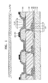
- FIG. 1 is a schematic sectional view of an organic light emitting display apparatus
- FIG. 2 is a schematic plan view of the organic light emitting display apparatus of FIG. 1 .
- a plurality of thin film transistors are disposed on a substrate 100, and an organic light emitting diode (OLED) is disposed above each of the TFTs.
- Each of the OLEDs include a pixel electrode 210 electrically connected to a corresponding TFT; a portion of an opposite electrode 220, the opposite electrode 220 being disposed above the substrate 100 and covering all of the substrate 100; and an intermediate layer 240 that is disposed between the pixel electrode 210 and the opposite electrode 220 and that includes at least an organic light emitting layer 230.
- the substrate 100 may include or be composed of glass.
- the substrate 100 of the organic light emitting display apparatus of the present embodiment is not limited thereto.
- the TFTs are disposed on the substrate 100.
- Each of the TFTs includes a gate electrode 150, source and drain electrodes 170, a semiconductor layer 130, a gate insulating layer 140, and an interlayer insulating layer 160.
- the structures of the TFTs are not limited thereto.
- the TFTs may be organic TFTs in which the semiconductor layer 130 includes an organic material, or silicon TFTs in which the semiconductor layer 130 includes silicon.
- a buffer layer 120 including silicon oxide and/or silicon nitride is further disposed between the TFTs and the substrate 100.
- Each of the OLEDs includes the pixel electrode 210, the opposite electrode 220 facing the pixel electrode 210, and the intermediate layer 240, which is interposed between the pixel electrode 210 and the opposite electrode 220 and further includes at least one organic layer.
- the intermediate layer 240 includes at least the organic light emitting layer 230, and may include a plurality of other suitable layers. These other suitable layers will be described later in more detail.
- the pixel electrode 210 functions as an anode, and the opposite electrode 220 functions as a cathode. In another embodiment, the pixel electrode 210 functions as a cathode, and the opposite electrode 220 functions as an anode.
- the pixel electrode 210 may be a transparent electrode or a reflective electrode.
- the pixel electrode 210 may include or be composed of ITO, IZO, ZnO, and/or In 2 O 3 .
- the pixel electrode 210 may include or be composed of: a reflective film including Ag, Mg, Al, Pt, Pd, Au, Ni, Nd, Ir, Cr, or a mixture thereof; and a transparent film including ITO, IZO, ZnO or In 2 O 3 , wherein the transparent film is formed on the reflective film.
- the opposite electrode 220 may also be a transparent electrode or a reflective electrode.
- the opposite electrode 220 is a transparent electrode, Li, Ca, LiF/Ca, LiF/Al, Al, Mg, or a mixture thereof is deposited to form a reflective film, and then an auxiliary electrode or a bus electrode may be formed on the reflective film using a transparent electrode forming material such as ITO, IZO, ZnO or In 2 O 3 , wherein the reflective film is disposed closer to the intermediate layer 240 (between the pixel electrode 210 and the opposite electrode 220) than the auxiliary electrode and the bus electrode.
- the opposite electrode 220 is a reflective electrode, Li, Ca, LiF/Ca, LiF/Al, Al, Mg, or a mixture thereof is deposited to form a reflective film.
- a pixel defining layer (PDL) 300 having a set or predetermined thickness is formed around the pixel electrode 210, covering edges (and/or edge portions) of the pixel electrode 210.
- the PDL 300 defines a light emitting region, and also widens the interval between the edges of the pixel electrode 210 and the opposite electrode 220 so as to prevent (or protect from) the generation of a strong electric field on the edges of the pixel electrode 210, thereby preventing (or protecting from) an occurrence of a short-circuit between the pixel electrode 210 and the opposite electrode 220.
- the intermediate layer 240 interposed between the pixel electrode 210 and the opposite electrode 220 includes the organic light emitting layer 230 and at least one other suitable organic layer.
- the organic light emitting layer 230 emits light by being electrically driven between the pixel electrode 210 and the opposite electrode 220.
- the organic light emitting layer 230 may include a low-molecular weight organic material and/or a polymer organic material.
- the intermediate layer 240 may include, for example, a hole transport layer (HTL) and a hole injection layer (HIL) sequentially formed in a direction from the organic light emitting layer 230 to the pixel electrode 210, and an electron transport layer (ETL) and an electron injection layer (EIL) sequentially formed in a direction from the organic light emitting layer 230 to the opposite electrode 220.
- HTL hole transport layer
- HIL hole injection layer
- ETL electron transport layer
- EIL electron injection layer sequentially formed in a direction from the organic light emitting layer 230 to the opposite electrode 220.
- each layer may have a single-layered structure or a multi-layered structure.
- Examples of a low-molecular weight organic material include copper phthalocyanine (CuPc), N,N'-Di naphthalene-1-yl -N,N'-diphenyl-benzidine (NPB), and tris-8-hydroxyquinoline aluminum (Alq3). These low-molecular weight organic materials may be vacuum deposited using a mask.
- CuPc copper phthalocyanine
- NPB N,N'-Di naphthalene-1-yl -N,N'-diphenyl-benzidine
- Alq3 tris-8-hydroxyquinoline aluminum
- the intermediate layer 240 may include the HTL and the organic light emitting layer 230, wherein the HTL may include poly- 2,4 -ethylene-dihydroxy thiophene (PEDOT) or polyaniline (PANI).
- PDOT poly- 2,4 -ethylene-dihydroxy thiophene
- PANI polyaniline
- a polymer organic material include poly-phenylenevinylene (PPV) and polyfluorene.
- the OLEDs are electrically connected to corresponding TFTs disposed under the OLEDs.
- the OLEDs may be disposed on the planarization layer 180, and the pixel electrodes 210 of the OLEDs are electrically connected to the corresponding TFTs through a contact hole formed in the planarization layer 180.
- the OLEDs are formed above the substrate 100, and the organic light emitting display apparatus further includes an encapsulation structure (and/or moisture absorbent structure) 270 on the opposite electrode 220 and for protecting the organic light emitting layer 230 from external moisture and/or oxygen and/or for sealing the OLEDs.
- an encapsulation structure (and/or moisture absorbent structure) 270 on the opposite electrode 220 and for protecting the organic light emitting layer 230 from external moisture and/or oxygen and/or for sealing the OLEDs.
- an opposite electrode bus line 250 is further formed on the opposite electrode 220 of the OLEDs.
- the opposite electrode bus line 250 is disposed between the pixel electrodes 210 of adjacent OLEDs.
- the opposite electrode bus line 250 may be formed using various suitable methods such as an aerosol jet printing method.
- the opposite electrode 220 is formed above the substrate 100 and completely covers the substrate 100, that is, entirely covers a display unit. However, when electrons or holes are injected to the organic light emitting layer 230, an IR drop occurs due to resistance of the opposite electrode 220. As a result, when signals are applied such that OLEDs are to emit light having the same luminosity, light having different luminosities may be emitted according to the positions of the OLEDs.
- a top emission-type organic light emitting display apparatus in which light generated in the organic light emitting layer 230 of the OLED is emitted through the opposite electrode 220, and not through substrate 100, has been developed.
- the opposite electrode 220 through which light penetrates, needs to be transparent and thin.
- an organic light emitting display apparatus is designed to prevent or protect from an IR drop due to the opposite electrode 220 by forming the opposite electrode bus line 250 on the opposite electrode 220, wherein the opposite electrode bus line 250 includes a conductive material.
- the opposite electrode bus line 250 may be formed in a non-light emitting area so as to not block light that is emitted through the opposite electrode 220 towards a top surface of the organic light emitting display apparatus.
- the opposite electrode bus line 250 may be disposed between the pixel electrodes 210 of adjacent OLEDs.
- the opposite electrode bus line 250 is formed in a stripe pattern in FIG. 2
- the opposite electrode bus line 250 may be formed in various other suitable patterns.
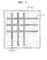
- the opposite electrode bus line 250 may also be formed in a mesh pattern, such as in an organic light emitting display apparatus according to another embodiment of the present invention as illustrated in FIG. 3 .
- the organic light emitting display apparatus includes a plurality of thin film transistors (TFTs) disposed on a substrate 100', and an organic light emitting diode (OLED) disposed above each of the TFTs.
- TFTs thin film transistors
- OLED organic light emitting diode
- Each of the OLEDs include a pixel electrode 210' electrically connected to a corresponding TFT; a portion of an opposite electrode, the opposite electrode being disposed above the substrate 100' and covering all of the substrate 100'; and an intermediate layer 240' that is disposed between the pixel electrode 210' and the opposite electrode and that includes at least an organic light emitting layer.
- an opposite electrode bus line 250' in a mesh pattern is further formed on the opposite electrode of the OLEDs.
- the opposite electrode bus line 250 may include silver, gold, copper, and/or nickel, i.e., may include at least one metal selected from the group consisting of silver, gold, copper, and nickel.
- the organic light emitting display apparatus further includes a black matrix 260 surrounding and/or covering the opposite electrode bus line 250 to lower the reflection rate of the opposite electrode bus line 250, thereby preventing or reducing a decrease in the contrast ratio of the organic light emitting display apparatus.
- the black matrix 260 may be formed in a non-light emitting area so as to not block light that is emitted through the opposite electrode 220 towards a top surface of the organic light emitting display apparatus.
- the black matrix 260 may be disposed between the pixel electrodes 210 of adjacent OLEDs, and surrounds and covers the opposite electrode bus line 250.
- the black matrix 260 is formed in a stripe pattern in FIG. 2
- the black matrix 260 may be formed in various other suitable patterns.
- a black matrix 260' formed in a mesh pattern is shown in the organic light emitting display apparatus according to the embodiment of the present invention illustrated in FIG. 3 .
- the black matrix 260 may include carbon black particles and/or graphite.
- the opposite electrode bus line 250 and the black matrix 260 may be formed in a non-light emitting area as described above.
- the opposite electrode bus line 250 and the black matrix 260 are formed by aerosol jet printing. In the aerosol jet printing, materials for forming the opposite electrode bus line 250 and the black matrix 260 are prepared in the form of an aerosol in which a solid and a liquid are mixed with gas, and the prepared aerosols are sprayed.
- the organic light emitting layer 230 and the intermediate layer 240 which are disposed under the opposite electrode bus line 250 and the black matrix 260 and include an organic material, may be damaged.
- the mask needs to be fixed, and if the mask and the substrate 100 are misaligned, all the pixels formed in the entire display region may be defective.
- the opposite electrode bus line 250 and the black matrix 260 are formed by aerosol jet printing, even if an aerosol jet deposition head, and the substrate 100 are temporarily misaligned; only some pixels may be defective and the quality of the organic light emitting display apparatus may be comparatively more reliable.
- the organic light emitting layer 230 and the intermediate layer 240 may be less damaged. Furthermore, a line-width is more freely controlled and thus, the opposite electrode bus line 250 and the black matrix 260 may be formed to have a fine line-width.
- the embodiments of the present invention have the following effects.
- an IR drop of an opposite electrode may be prevented or reduced by forming an opposite electrode bus line between adjacent pixel electrodes on the opposite electrode.
- the IR drop of the opposite electrode and a decrease in a contrast ratio may be simultaneously or concurrently prevented or reduced by surrounding and/or covering the opposite electrode bus line with a black matrix.
- the quality of an organic light emitting display apparatus may be more reliable by forming an opposite electrode bus line and a black matrix each having a fine line-width by aerosol jet printing.
Landscapes
- Engineering & Computer Science (AREA)
- Physics & Mathematics (AREA)
- Optics & Photonics (AREA)
- Microelectronics & Electronic Packaging (AREA)
- Manufacturing & Machinery (AREA)
- Electroluminescent Light Sources (AREA)
- Devices For Indicating Variable Information By Combining Individual Elements (AREA)
Claims (7)
- Verfahren zur Herstellung einer organischen Licht emittierenden Anzeigevorrichtung, wobei das Verfahren umfasst:Ausbilden einer Vielzahl von Dünnfilmtransistoren auf einem Substrat (100);Ausbilden einer Vielzahl von organischen Licht emittierenden Dioden, wobei jede der organischen Licht emittierenden Dioden umfasst:eine Pixelelektrode (210), die mit einem entsprechenden der Dünnfilmtransistoren elektrisch verbunden ist,eine Zwischenschicht (240) auf der Pixelelektrode und mit mindestens einer organischen Licht emittierenden Schicht (230),einen Abschnitt einer Gegenelektrode (220), wobei die Gegenelektrode sich über dem Substrat befindet und das gesamte Substrat bedeckt; undeine Pixeldefinitionsschicht (300) mit einer festgelegten Dicke, wobei die Pixeldefinitionsschicht sich um Kantenabschnitte der Pixelelektroden (210) herum befindet und die Gegenelektrode (220) auf der Pixeldefinitionsschicht (300) angeordnet ist;Ausbilden einer Gegenelektrodenbusleitung (250), die auf der Gegenelektrode (220) angeordnet ist, wobei die Gegenelektrodenbusleitung (250) auf der Pixeldefinitionsschicht (300) zwischen benachbarten Pixel-Elektroden (210) der organischen Licht emittierenden Dioden angeordnet ist; undAusilden einer Schwarzmatrix (260), die die Gegenelektrodenbusleitung (250) bedeckt;dadurch gekennzeichnet, dass die Gegenelektrodenbusleitung (250) und die Schwarzmatrix (260) durch Aerosolstrahldruck ausgebildet werden, so dass die Schwarzmatrix (260) Seitenflächen und eine obere Flächen der Gegenelektrodenbusleitung (250) bedeckt.
- Verfahren nach Anspruch 1, wobei die Gegenelektrodenbusleitung (250) ein Streifenmuster hat.
- Verfahren nach Anspruch 1, wobei die Gegenelektrodenbusleitung (250) ein Gittermuster hat.
- Verfahren nach einem der vorhergehenden Ansprüche, wobei die Gegenelektrodenbusleitung (250) ein Metall aufweist, das aus der Gruppe ausgewählt ist, bestehend aus Silber, Gold, Kupfer, Nickel und Kombinationen daraus.
- Verfahren nach einem der vorhergehenden Ansprüche, ferner umfassend:Ausbilden einer Planarisierungsschicht (180), die die Dünnfilmtransistoren bedeckt, wobei die organischen Licht emittierenden Dioden auf der Planarisierungsschicht (180) angeordnet sind und die Pixelelektroden (210) der organischen Licht emittierenden Dioden mit den Dünnfilmtransistoren über in der Planarisierungsschicht ausgebildete Kontaktlöcher elektrisch verbunden sind.
- Verfahren nach einem der vorhergehenden Ansprüche, ferner umfassend:Ausbilden einer Verkapselungsstruktur (270) auf der Gegenelektrode (220), wobei die organischen Licht emittierenden Dioden durch die Verkapselungsstruktur versiegelt werden.
- Verfahren nach einem der vorhergehenden Ansprüche, ferner umfassend:Ausbilden einer Pufferschicht (120) auf dem Substrat (100).
Applications Claiming Priority (1)
| Application Number | Priority Date | Filing Date | Title |
|---|---|---|---|
| KR1020090073519A KR101084171B1 (ko) | 2009-08-10 | 2009-08-10 | 유기 발광 디스플레이 장치 및 유기 발광 디스플레이 장치의 제조 방법 |
Publications (3)
| Publication Number | Publication Date |
|---|---|
| EP2284899A2 EP2284899A2 (de) | 2011-02-16 |
| EP2284899A3 EP2284899A3 (de) | 2011-11-23 |
| EP2284899B1 true EP2284899B1 (de) | 2015-11-04 |
Family
ID=43069840
Family Applications (1)
| Application Number | Title | Priority Date | Filing Date |
|---|---|---|---|
| EP10251423.9A Active EP2284899B1 (de) | 2009-08-10 | 2010-08-10 | Verfahren zur Herstellung einer organischen lichtemittierenden Anzeigevorrichtung |
Country Status (5)
| Country | Link |
|---|---|
| US (1) | US8362469B2 (de) |
| EP (1) | EP2284899B1 (de) |
| JP (2) | JP2011040380A (de) |
| KR (1) | KR101084171B1 (de) |
| CN (1) | CN101997022B (de) |
Families Citing this family (52)
| Publication number | Priority date | Publication date | Assignee | Title |
|---|---|---|---|---|
| KR101705822B1 (ko) * | 2010-10-27 | 2017-02-23 | 삼성디스플레이 주식회사 | 유기 발광 표시 장치 및 그 제조 방법 |
| JP5900351B2 (ja) * | 2011-02-02 | 2016-04-06 | コニカミノルタ株式会社 | 有機エレクトロルミネッセンス素子の製造方法 |
| JP5684370B2 (ja) * | 2011-03-29 | 2015-03-11 | Necライティング株式会社 | 有機el発光装置、有機el発光装置の製造方法及び有機el照明装置 |
| JP5743669B2 (ja) * | 2011-04-18 | 2015-07-01 | キヤノン株式会社 | 表示装置及びその製造方法 |
| DE102011106390A1 (de) * | 2011-07-01 | 2013-01-03 | Fraunhofer-Gesellschaft zur Förderung der angewandten Forschung e.V. | Organische Leuchtdioden oder organische photovoltaische Elemente sowie ein Herstellungsverfahren |
| TW201321871A (zh) * | 2011-11-29 | 2013-06-01 | Au Optronics Corp | 顯示面板及其製作方法 |
| JP6110695B2 (ja) * | 2012-03-16 | 2017-04-05 | 株式会社半導体エネルギー研究所 | 発光装置 |
| KR102000709B1 (ko) * | 2012-08-31 | 2019-09-30 | 삼성디스플레이 주식회사 | 디스플레이 패널의 제조방법 |
| US9088003B2 (en) * | 2013-03-06 | 2015-07-21 | Apple Inc. | Reducing sheet resistance for common electrode in top emission organic light emitting diode display |
| KR102080010B1 (ko) * | 2013-06-04 | 2020-02-24 | 삼성디스플레이 주식회사 | 박막증착장치 및 이를 이용한 유기발광표시장치의 제조방법. |
| KR20150055919A (ko) * | 2013-11-14 | 2015-05-22 | 삼성디스플레이 주식회사 | 박막 트랜지스터, 그 제조 방법 및 이를 포함하는 유기 발광 표시 장치 |
| TWI566395B (zh) | 2013-11-18 | 2017-01-11 | 元太科技工業股份有限公司 | 有機發光二極體顯示器及其製造方法 |
| US9612492B2 (en) | 2013-11-26 | 2017-04-04 | Apple Inc. | Border masking structures for liquid crystal display |
| KR102181238B1 (ko) | 2014-02-12 | 2020-11-23 | 삼성디스플레이 주식회사 | 유기 발광 표시 장치 및 유기 발광 표시 장치의 제조 방법 |
| KR102206554B1 (ko) * | 2014-05-08 | 2021-01-21 | 엘지디스플레이 주식회사 | 유기 발광 표시 장치 및 그 제조 방법 |
| KR20160010707A (ko) * | 2014-07-17 | 2016-01-28 | 삼성디스플레이 주식회사 | 유기발광 디스플레이 장치 및 그 제조방법 |
| KR102246294B1 (ko) * | 2014-08-04 | 2021-04-30 | 삼성디스플레이 주식회사 | 유기발광표시장치 및 그 제조 방법 |
| KR102263261B1 (ko) * | 2014-08-05 | 2021-06-10 | 엘지디스플레이 주식회사 | 유기 발광 표시 장치 및 유기 발광 표시 장치 제조 방법 |
| CN104157675A (zh) * | 2014-08-05 | 2014-11-19 | 京东方科技集团股份有限公司 | 一种oled显示器件及其制作方法、显示装置 |
| KR102360783B1 (ko) * | 2014-09-16 | 2022-02-10 | 삼성디스플레이 주식회사 | 디스플레이 장치 |
| KR102284756B1 (ko) | 2014-09-23 | 2021-08-03 | 삼성디스플레이 주식회사 | 디스플레이 장치 |
| CN105788516B (zh) * | 2014-12-23 | 2019-03-26 | 昆山国显光电有限公司 | Oled显示面板及其制造方法和有源矩阵有机发光显示器 |
| JP6685675B2 (ja) * | 2015-09-07 | 2020-04-22 | 株式会社Joled | 有機el素子、それを用いた有機el表示パネル、及び有機el表示パネルの製造方法 |
| CA3002752A1 (en) | 2015-10-26 | 2017-05-04 | Oti Lumionics Inc. | Method for patterning a coating on a surface and device including a patterned coating |
| KR102579751B1 (ko) * | 2016-07-05 | 2023-09-19 | 삼성디스플레이 주식회사 | 디스플레이 장치 및 디스플레이 장치의 제조방법 |
| US11152587B2 (en) | 2016-08-15 | 2021-10-19 | Oti Lumionics Inc. | Light transmissive electrode for light emitting devices |
| CN118215324B (zh) | 2016-12-02 | 2025-08-15 | Oti照明公司 | 包括设置在发射区域上面的导电涂层的器件及其方法 |
| KR20180097808A (ko) * | 2017-02-23 | 2018-09-03 | 삼성디스플레이 주식회사 | 표시 장치 및 그것의 제조 방법 |
| JP6583343B2 (ja) * | 2017-04-24 | 2019-10-02 | 王子ホールディングス株式会社 | 透明電極付半導体素子用基板、有機発光ダイオード素子、または有機薄膜太陽電池素子 |
| JP2017168448A (ja) * | 2017-04-24 | 2017-09-21 | 王子ホールディングス株式会社 | 半導体素子用基板、有機発光ダイオード素子、及び有機薄膜太陽電池素子 |
| CN116583131A (zh) | 2017-04-26 | 2023-08-11 | Oti照明公司 | 用于图案化表面上覆层的方法和包括图案化覆层的装置 |
| WO2018211460A1 (en) | 2017-05-17 | 2018-11-22 | Oti Lumionics Inc. | Method for selectively depositing a conductive coating over a patterning coating and device including a conductive coating |
| KR102422750B1 (ko) * | 2017-12-06 | 2022-07-20 | 삼성디스플레이 주식회사 | 유기 발광 표시 장치 및 이의 제조 방법 |
| KR102468861B1 (ko) | 2017-12-22 | 2022-11-18 | 엘지디스플레이 주식회사 | 전계발광표시장치 |
| KR102439307B1 (ko) * | 2018-01-29 | 2022-09-02 | 삼성디스플레이 주식회사 | 유기발광표시장치 및 그 제조방법 |
| US11751415B2 (en) | 2018-02-02 | 2023-09-05 | Oti Lumionics Inc. | Materials for forming a nucleation-inhibiting coating and devices incorporating same |
| CN108336116B (zh) * | 2018-02-08 | 2022-03-08 | 京东方科技集团股份有限公司 | 一种oled阵列基板及其制备方法、显示装置 |
| US10627673B2 (en) * | 2018-04-06 | 2020-04-21 | Glo Ab | Light emitting diode array containing a multilayer bus electrode and method of making the same |
| WO2019215591A1 (en) | 2018-05-07 | 2019-11-14 | Oti Lumionics Inc. | Method for providing an auxiliary electrode and device including an auxiliary electrode |
| JP2022508040A (ja) | 2018-11-23 | 2022-01-19 | オーティーアイ ルミオニクス インコーポレーテッド | 光透過領域を含むオプトエレクトロニクスデバイス |
| KR20250160226A (ko) | 2019-03-07 | 2025-11-11 | 오티아이 루미오닉스 인크. | 핵생성 억제 코팅물 형성용 재료 및 이를 포함하는 디바이스 |
| CN113950630A (zh) | 2019-04-18 | 2022-01-18 | Oti照明公司 | 用于形成成核抑制涂层的材料和结合所述成核抑制涂层的装置 |
| US12069938B2 (en) | 2019-05-08 | 2024-08-20 | Oti Lumionics Inc. | Materials for forming a nucleation-inhibiting coating and devices incorporating same |
| US11832473B2 (en) | 2019-06-26 | 2023-11-28 | Oti Lumionics Inc. | Optoelectronic device including light transmissive regions, with light diffraction characteristics |
| KR20240134240A (ko) | 2019-06-26 | 2024-09-06 | 오티아이 루미오닉스 인크. | 광 회절 특성을 갖는 광 투과 영역을 포함하는 광전자 디바이스 |
| CN114342068A (zh) | 2019-08-09 | 2022-04-12 | Oti照明公司 | 包含辅助电极和分区的光电子装置 |
| KR102931641B1 (ko) | 2019-12-24 | 2026-02-26 | 오티아이 루미오닉스 인크. | 캡핑 층을 포함하는 발광 장치 및 그 제조방법 |
| CN111599937B (zh) * | 2020-05-25 | 2022-10-14 | 视涯科技股份有限公司 | 一种有机发光显示面板及有机发光显示面板制备方法 |
| US11985841B2 (en) | 2020-12-07 | 2024-05-14 | Oti Lumionics Inc. | Patterning a conductive deposited layer using a nucleation inhibiting coating and an underlying metallic coating |
| CN112928150B (zh) * | 2021-04-09 | 2023-06-06 | 合肥京东方卓印科技有限公司 | 一种显示基板及其制备方法、显示装置 |
| KR20230118212A (ko) * | 2022-02-03 | 2023-08-11 | 삼성디스플레이 주식회사 | 표시 장치 및 이의 제조 방법 |
| KR20240022055A (ko) * | 2022-08-10 | 2024-02-20 | 삼성디스플레이 주식회사 | 표시 장치 및 표시 장치의 제조 방법 |
Citations (3)
| Publication number | Priority date | Publication date | Assignee | Title |
|---|---|---|---|---|
| JP2002352963A (ja) * | 2001-05-23 | 2002-12-06 | Sony Corp | 表示装置 |
| US20070108899A1 (en) * | 2005-11-15 | 2007-05-17 | Samsung Electronics Co., Ltd | Display device and fabricating method thereof |
| US20090096371A1 (en) * | 2007-10-10 | 2009-04-16 | Hitachi Displays, Ltd. | Organic electro-luminescent display device |
Family Cites Families (30)
| Publication number | Priority date | Publication date | Assignee | Title |
|---|---|---|---|---|
| JPH08242056A (ja) * | 1995-03-03 | 1996-09-17 | Hokuriku Electric Ind Co Ltd | コンデンサ付き回路基板及びその製造方法 |
| JP2003152299A (ja) * | 2001-07-10 | 2003-05-23 | Canon Inc | 配線接続構造及びその製造方法 |
| JP2003089866A (ja) * | 2001-09-19 | 2003-03-28 | Canon Inc | 超微粒子膜製造装置及び超微粒子膜の形成方法 |
| JP4156431B2 (ja) * | 2002-04-23 | 2008-09-24 | 株式会社半導体エネルギー研究所 | 発光装置およびその作製方法 |
| JP2004048032A (ja) * | 2002-07-12 | 2004-02-12 | Sharp Corp | 配線構造、表示装置および能動素子基板 |
| US7026658B2 (en) * | 2003-03-13 | 2006-04-11 | Samsung Sdi, Co., Ltd. | Electrical conductors in an electroluminescent display device |
| JP2005019211A (ja) * | 2003-06-26 | 2005-01-20 | Casio Comput Co Ltd | El表示パネル及びel表示パネルの製造方法 |
| JP4623701B2 (ja) * | 2003-08-29 | 2011-02-02 | 株式会社 日立ディスプレイズ | カラーフィルター用着色組成物及びこの着色組成物で形成したカラーフィルターを用いた表示装置 |
| WO2005039814A2 (en) | 2003-09-26 | 2005-05-06 | Optomec Design Company | Laser processing for heat-sensitive mesoscale deposition |
| KR100552972B1 (ko) | 2003-10-09 | 2006-02-15 | 삼성에스디아이 주식회사 | 평판표시장치 및 그의 제조방법 |
| KR100551027B1 (ko) | 2003-10-09 | 2006-02-13 | 삼성에스디아이 주식회사 | 유기 전계 발광 표시 장치 |
| KR20050048705A (ko) | 2003-11-19 | 2005-05-25 | 삼성에스디아이 주식회사 | 상부 전극 버스 라인을 구비하는 유기 전계 발광 소자 |
| JP2005305427A (ja) * | 2004-03-26 | 2005-11-04 | Fuji Photo Film Co Ltd | ノズル装置、それを用いた成膜装置及び方法、無機エレクトロルミネッセンス素子、インクジェットヘッド、及び、超音波トランスデューサアレイ |
| KR100656496B1 (ko) * | 2004-09-21 | 2006-12-11 | 삼성에스디아이 주식회사 | 풀 칼라 유기 전계 발광 표시 소자 및 그 제조방법 |
| WO2006041027A1 (ja) * | 2004-10-13 | 2006-04-20 | Sharp Kabushiki Kaisha | 機能基板 |
| US7674671B2 (en) * | 2004-12-13 | 2010-03-09 | Optomec Design Company | Aerodynamic jetting of aerosolized fluids for fabrication of passive structures |
| JP4657914B2 (ja) * | 2005-01-26 | 2011-03-23 | ルネサスエレクトロニクス株式会社 | 半導体装置及びその製造方法 |
| JP2006326523A (ja) * | 2005-05-27 | 2006-12-07 | Canon Inc | 成膜方法、該成膜方法により形成された圧電膜、および該圧電膜を備えた圧電素子、ならびに該圧電素子を用いたインクジェット装置 |
| CN1882207A (zh) * | 2005-06-16 | 2006-12-20 | 悠景科技股份有限公司 | 具有高发光效率与高灰阶对比的有机电致发光显示器 |
| KR100662557B1 (ko) * | 2005-11-15 | 2006-12-28 | 삼성전자주식회사 | 표시장치와 그 제조방법 |
| EP1987543A1 (de) * | 2006-01-25 | 2008-11-05 | Fraunhofer-Gesellschaft zur Förderung der angewandten Forschung e.V. | Verfahren zum herstellen einer metallischen kontaktstruktur einer solarzelle |
| JP2007227129A (ja) * | 2006-02-23 | 2007-09-06 | Seiko Epson Corp | 有機el装置及び有機el装置の製造方法 |
| KR100708750B1 (ko) * | 2006-04-21 | 2007-04-17 | 삼성에스디아이 주식회사 | 유기 발광 디스플레이 장치의 제조방법 및 유기 발광디스플레이 장치 |
| JP2007311137A (ja) * | 2006-05-17 | 2007-11-29 | Toyota Motor Corp | 燃料電池用セパレータの製造方法、および燃料電池用セパレータ |
| CN101118915B (zh) * | 2007-08-08 | 2011-08-10 | 友达光电股份有限公司 | 光感测元件及其制作方法 |
| JP2009123696A (ja) * | 2007-10-26 | 2009-06-04 | Mitsubishi Chemicals Corp | 有機電界発光素子、画像表示装置、及び有機電界発光素子の製造方法 |
| JP4920548B2 (ja) * | 2007-10-31 | 2012-04-18 | 株式会社 日立ディスプレイズ | 表示装置 |
| TWI365005B (en) * | 2008-01-04 | 2012-05-21 | Chimei Innolux Corp | Organic light emitting diode (oled) display devices, modules, and electronic devices |
| CN101488515B (zh) * | 2008-01-17 | 2012-08-29 | 奇美电子股份有限公司 | 有机发光显示器装置、模块及电子装置 |
| TWI413249B (zh) * | 2008-10-22 | 2013-10-21 | Wintek Corp | 有機發光二極體顯示裝置及其製造方法 |
-
2009
- 2009-08-10 KR KR1020090073519A patent/KR101084171B1/ko active Active
-
2010
- 2010-08-02 JP JP2010173752A patent/JP2011040380A/ja active Pending
- 2010-08-10 US US12/854,124 patent/US8362469B2/en active Active
- 2010-08-10 CN CN201010251358.3A patent/CN101997022B/zh active Active
- 2010-08-10 EP EP10251423.9A patent/EP2284899B1/de active Active
-
2013
- 2013-12-06 JP JP2013253442A patent/JP5969450B2/ja active Active
Patent Citations (3)
| Publication number | Priority date | Publication date | Assignee | Title |
|---|---|---|---|---|
| JP2002352963A (ja) * | 2001-05-23 | 2002-12-06 | Sony Corp | 表示装置 |
| US20070108899A1 (en) * | 2005-11-15 | 2007-05-17 | Samsung Electronics Co., Ltd | Display device and fabricating method thereof |
| US20090096371A1 (en) * | 2007-10-10 | 2009-04-16 | Hitachi Displays, Ltd. | Organic electro-luminescent display device |
Non-Patent Citations (1)
| Title |
|---|
| DATABASE WPI Week 200329, Derwent World Patents Index; Class P85, AN 2003-293510 * |
Also Published As
| Publication number | Publication date |
|---|---|
| EP2284899A3 (de) | 2011-11-23 |
| CN101997022B (zh) | 2016-06-08 |
| JP2014041848A (ja) | 2014-03-06 |
| US20110031500A1 (en) | 2011-02-10 |
| KR20110016030A (ko) | 2011-02-17 |
| KR101084171B1 (ko) | 2011-11-17 |
| CN101997022A (zh) | 2011-03-30 |
| JP5969450B2 (ja) | 2016-08-17 |
| US8362469B2 (en) | 2013-01-29 |
| EP2284899A2 (de) | 2011-02-16 |
| JP2011040380A (ja) | 2011-02-24 |
Similar Documents
| Publication | Publication Date | Title |
|---|---|---|
| EP2284899B1 (de) | Verfahren zur Herstellung einer organischen lichtemittierenden Anzeigevorrichtung | |
| US11665921B2 (en) | Organic light-emitting display apparatus and method of manufacturing the same | |
| US11476297B2 (en) | Display apparatus | |
| KR100592273B1 (ko) | 평판 디스플레이 장치 | |
| KR102151752B1 (ko) | 유기발광 디스플레이 장치 및 그 제조방법 | |
| CN101202298B (zh) | 有机发光显示设备 | |
| KR100581903B1 (ko) | 전계 발광 디스플레이 장치 | |
| US7538488B2 (en) | Flat panel display | |
| EP2144292A2 (de) | Display aus organischen Leuchtdioden und dessen Herstellungsmethode | |
| KR100615222B1 (ko) | 전계 발광 디스플레이 장치 및 이의 제조 방법 | |
| US9299950B2 (en) | Organic light emitting display apparatus | |
| US8888547B2 (en) | Organic light-emitting display apparatus and method of manufacturing the same | |
| KR100563065B1 (ko) | 전계 발광 디스플레이 장치 및 이의 제조 방법 | |
| KR100813849B1 (ko) | 유기 발광 디스플레이 장치 | |
| KR20200105775A (ko) | 유기발광 디스플레이 장치 및 그 제조방법 | |
| KR100708750B1 (ko) | 유기 발광 디스플레이 장치의 제조방법 및 유기 발광디스플레이 장치 | |
| KR100764773B1 (ko) | 유기 발광 다이오드 디스플레이 장치 및 그 제조 방법 | |
| KR100647606B1 (ko) | 전계 발광 디스플레이 장치의 제조 방법 |
Legal Events
| Date | Code | Title | Description |
|---|---|---|---|
| PUAI | Public reference made under article 153(3) epc to a published international application that has entered the european phase |
Free format text: ORIGINAL CODE: 0009012 |
|
| AK | Designated contracting states |
Kind code of ref document: A2 Designated state(s): AL AT BE BG CH CY CZ DE DK EE ES FI FR GB GR HR HU IE IS IT LI LT LU LV MC MK MT NL NO PL PT RO SE SI SK SM TR |
|
| AX | Request for extension of the european patent |
Extension state: BA ME RS |
|
| RIN1 | Information on inventor provided before grant (corrected) |
Inventor name: SUH, MIN-CHUL |
|
| PUAL | Search report despatched |
Free format text: ORIGINAL CODE: 0009013 |
|
| AK | Designated contracting states |
Kind code of ref document: A3 Designated state(s): AL AT BE BG CH CY CZ DE DK EE ES FI FR GB GR HR HU IE IS IT LI LT LU LV MC MK MT NL NO PL PT RO SE SI SK SM TR |
|
| AX | Request for extension of the european patent |
Extension state: BA ME RS |
|
| RIC1 | Information provided on ipc code assigned before grant |
Ipc: H01L 51/52 20060101ALI20111017BHEP Ipc: H01L 27/32 20060101AFI20111017BHEP |
|
| 17P | Request for examination filed |
Effective date: 20120518 |
|
| 17Q | First examination report despatched |
Effective date: 20120802 |
|
| RAP1 | Party data changed (applicant data changed or rights of an application transferred) |
Owner name: SAMSUNG DISPLAY CO., LTD. |
|
| GRAP | Despatch of communication of intention to grant a patent |
Free format text: ORIGINAL CODE: EPIDOSNIGR1 |
|
| INTG | Intention to grant announced |
Effective date: 20150515 |
|
| GRAS | Grant fee paid |
Free format text: ORIGINAL CODE: EPIDOSNIGR3 |
|
| RAP1 | Party data changed (applicant data changed or rights of an application transferred) |
Owner name: SAMSUNG DISPLAY CO., LTD. |
|
| GRAA | (expected) grant |
Free format text: ORIGINAL CODE: 0009210 |
|
| AK | Designated contracting states |
Kind code of ref document: B1 Designated state(s): AL AT BE BG CH CY CZ DE DK EE ES FI FR GB GR HR HU IE IS IT LI LT LU LV MC MK MT NL NO PL PT RO SE SI SK SM TR |
|
| REG | Reference to a national code |
Ref country code: GB Ref legal event code: FG4D |
|
| REG | Reference to a national code |
Ref country code: CH Ref legal event code: EP |
|
| REG | Reference to a national code |
Ref country code: AT Ref legal event code: REF Ref document number: 759726 Country of ref document: AT Kind code of ref document: T Effective date: 20151115 |
|
| REG | Reference to a national code |
Ref country code: IE Ref legal event code: FG4D |
|
| REG | Reference to a national code |
Ref country code: DE Ref legal event code: R096 Ref document number: 602010028740 Country of ref document: DE |
|
| REG | Reference to a national code |
Ref country code: NL Ref legal event code: MP Effective date: 20151104 |
|
| REG | Reference to a national code |
Ref country code: LT Ref legal event code: MG4D |
|
| REG | Reference to a national code |
Ref country code: AT Ref legal event code: MK05 Ref document number: 759726 Country of ref document: AT Kind code of ref document: T Effective date: 20151104 |
|
| PG25 | Lapsed in a contracting state [announced via postgrant information from national office to epo] |
Ref country code: IT Free format text: LAPSE BECAUSE OF FAILURE TO SUBMIT A TRANSLATION OF THE DESCRIPTION OR TO PAY THE FEE WITHIN THE PRESCRIBED TIME-LIMIT Effective date: 20151104 Ref country code: NO Free format text: LAPSE BECAUSE OF FAILURE TO SUBMIT A TRANSLATION OF THE DESCRIPTION OR TO PAY THE FEE WITHIN THE PRESCRIBED TIME-LIMIT Effective date: 20160204 Ref country code: IS Free format text: LAPSE BECAUSE OF FAILURE TO SUBMIT A TRANSLATION OF THE DESCRIPTION OR TO PAY THE FEE WITHIN THE PRESCRIBED TIME-LIMIT Effective date: 20160304 Ref country code: HR Free format text: LAPSE BECAUSE OF FAILURE TO SUBMIT A TRANSLATION OF THE DESCRIPTION OR TO PAY THE FEE WITHIN THE PRESCRIBED TIME-LIMIT Effective date: 20151104 Ref country code: NL Free format text: LAPSE BECAUSE OF FAILURE TO SUBMIT A TRANSLATION OF THE DESCRIPTION OR TO PAY THE FEE WITHIN THE PRESCRIBED TIME-LIMIT Effective date: 20151104 Ref country code: LT Free format text: LAPSE BECAUSE OF FAILURE TO SUBMIT A TRANSLATION OF THE DESCRIPTION OR TO PAY THE FEE WITHIN THE PRESCRIBED TIME-LIMIT Effective date: 20151104 Ref country code: ES Free format text: LAPSE BECAUSE OF FAILURE TO SUBMIT A TRANSLATION OF THE DESCRIPTION OR TO PAY THE FEE WITHIN THE PRESCRIBED TIME-LIMIT Effective date: 20151104 |
|
| PG25 | Lapsed in a contracting state [announced via postgrant information from national office to epo] |
Ref country code: AT Free format text: LAPSE BECAUSE OF FAILURE TO SUBMIT A TRANSLATION OF THE DESCRIPTION OR TO PAY THE FEE WITHIN THE PRESCRIBED TIME-LIMIT Effective date: 20151104 Ref country code: PT Free format text: LAPSE BECAUSE OF FAILURE TO SUBMIT A TRANSLATION OF THE DESCRIPTION OR TO PAY THE FEE WITHIN THE PRESCRIBED TIME-LIMIT Effective date: 20160304 Ref country code: FI Free format text: LAPSE BECAUSE OF FAILURE TO SUBMIT A TRANSLATION OF THE DESCRIPTION OR TO PAY THE FEE WITHIN THE PRESCRIBED TIME-LIMIT Effective date: 20151104 Ref country code: GR Free format text: LAPSE BECAUSE OF FAILURE TO SUBMIT A TRANSLATION OF THE DESCRIPTION OR TO PAY THE FEE WITHIN THE PRESCRIBED TIME-LIMIT Effective date: 20160205 Ref country code: LV Free format text: LAPSE BECAUSE OF FAILURE TO SUBMIT A TRANSLATION OF THE DESCRIPTION OR TO PAY THE FEE WITHIN THE PRESCRIBED TIME-LIMIT Effective date: 20151104 Ref country code: SE Free format text: LAPSE BECAUSE OF FAILURE TO SUBMIT A TRANSLATION OF THE DESCRIPTION OR TO PAY THE FEE WITHIN THE PRESCRIBED TIME-LIMIT Effective date: 20151104 Ref country code: PL Free format text: LAPSE BECAUSE OF FAILURE TO SUBMIT A TRANSLATION OF THE DESCRIPTION OR TO PAY THE FEE WITHIN THE PRESCRIBED TIME-LIMIT Effective date: 20151104 |
|
| REG | Reference to a national code |
Ref country code: FR Ref legal event code: PLFP Year of fee payment: 7 |
|
| PG25 | Lapsed in a contracting state [announced via postgrant information from national office to epo] |
Ref country code: CZ Free format text: LAPSE BECAUSE OF FAILURE TO SUBMIT A TRANSLATION OF THE DESCRIPTION OR TO PAY THE FEE WITHIN THE PRESCRIBED TIME-LIMIT Effective date: 20151104 |
|
| REG | Reference to a national code |
Ref country code: DE Ref legal event code: R097 Ref document number: 602010028740 Country of ref document: DE |
|
| PG25 | Lapsed in a contracting state [announced via postgrant information from national office to epo] |
Ref country code: SK Free format text: LAPSE BECAUSE OF FAILURE TO SUBMIT A TRANSLATION OF THE DESCRIPTION OR TO PAY THE FEE WITHIN THE PRESCRIBED TIME-LIMIT Effective date: 20151104 Ref country code: SM Free format text: LAPSE BECAUSE OF FAILURE TO SUBMIT A TRANSLATION OF THE DESCRIPTION OR TO PAY THE FEE WITHIN THE PRESCRIBED TIME-LIMIT Effective date: 20151104 Ref country code: EE Free format text: LAPSE BECAUSE OF FAILURE TO SUBMIT A TRANSLATION OF THE DESCRIPTION OR TO PAY THE FEE WITHIN THE PRESCRIBED TIME-LIMIT Effective date: 20151104 Ref country code: RO Free format text: LAPSE BECAUSE OF FAILURE TO SUBMIT A TRANSLATION OF THE DESCRIPTION OR TO PAY THE FEE WITHIN THE PRESCRIBED TIME-LIMIT Effective date: 20151104 Ref country code: DK Free format text: LAPSE BECAUSE OF FAILURE TO SUBMIT A TRANSLATION OF THE DESCRIPTION OR TO PAY THE FEE WITHIN THE PRESCRIBED TIME-LIMIT Effective date: 20151104 |
|
| PLBE | No opposition filed within time limit |
Free format text: ORIGINAL CODE: 0009261 |
|
| STAA | Information on the status of an ep patent application or granted ep patent |
Free format text: STATUS: NO OPPOSITION FILED WITHIN TIME LIMIT |
|
| 26N | No opposition filed |
Effective date: 20160805 |
|
| PG25 | Lapsed in a contracting state [announced via postgrant information from national office to epo] |
Ref country code: SI Free format text: LAPSE BECAUSE OF FAILURE TO SUBMIT A TRANSLATION OF THE DESCRIPTION OR TO PAY THE FEE WITHIN THE PRESCRIBED TIME-LIMIT Effective date: 20151104 |
|
| PG25 | Lapsed in a contracting state [announced via postgrant information from national office to epo] |
Ref country code: BE Free format text: LAPSE BECAUSE OF FAILURE TO SUBMIT A TRANSLATION OF THE DESCRIPTION OR TO PAY THE FEE WITHIN THE PRESCRIBED TIME-LIMIT Effective date: 20151104 |
|
| PG25 | Lapsed in a contracting state [announced via postgrant information from national office to epo] |
Ref country code: MC Free format text: LAPSE BECAUSE OF FAILURE TO SUBMIT A TRANSLATION OF THE DESCRIPTION OR TO PAY THE FEE WITHIN THE PRESCRIBED TIME-LIMIT Effective date: 20151104 |
|
| REG | Reference to a national code |
Ref country code: CH Ref legal event code: PL |
|
| PG25 | Lapsed in a contracting state [announced via postgrant information from national office to epo] |
Ref country code: CH Free format text: LAPSE BECAUSE OF NON-PAYMENT OF DUE FEES Effective date: 20160831 Ref country code: LI Free format text: LAPSE BECAUSE OF NON-PAYMENT OF DUE FEES Effective date: 20160831 |
|
| REG | Reference to a national code |
Ref country code: IE Ref legal event code: MM4A |
|
| REG | Reference to a national code |
Ref country code: FR Ref legal event code: PLFP Year of fee payment: 8 |
|
| PG25 | Lapsed in a contracting state [announced via postgrant information from national office to epo] |
Ref country code: IE Free format text: LAPSE BECAUSE OF NON-PAYMENT OF DUE FEES Effective date: 20160810 |
|
| PG25 | Lapsed in a contracting state [announced via postgrant information from national office to epo] |
Ref country code: LU Free format text: LAPSE BECAUSE OF NON-PAYMENT OF DUE FEES Effective date: 20160810 |
|
| PG25 | Lapsed in a contracting state [announced via postgrant information from national office to epo] |
Ref country code: HU Free format text: LAPSE BECAUSE OF FAILURE TO SUBMIT A TRANSLATION OF THE DESCRIPTION OR TO PAY THE FEE WITHIN THE PRESCRIBED TIME-LIMIT; INVALID AB INITIO Effective date: 20100810 Ref country code: CY Free format text: LAPSE BECAUSE OF FAILURE TO SUBMIT A TRANSLATION OF THE DESCRIPTION OR TO PAY THE FEE WITHIN THE PRESCRIBED TIME-LIMIT Effective date: 20151104 |
|
| PG25 | Lapsed in a contracting state [announced via postgrant information from national office to epo] |
Ref country code: TR Free format text: LAPSE BECAUSE OF FAILURE TO SUBMIT A TRANSLATION OF THE DESCRIPTION OR TO PAY THE FEE WITHIN THE PRESCRIBED TIME-LIMIT Effective date: 20151104 Ref country code: MT Free format text: LAPSE BECAUSE OF NON-PAYMENT OF DUE FEES Effective date: 20160831 Ref country code: MK Free format text: LAPSE BECAUSE OF FAILURE TO SUBMIT A TRANSLATION OF THE DESCRIPTION OR TO PAY THE FEE WITHIN THE PRESCRIBED TIME-LIMIT Effective date: 20151104 |
|
| REG | Reference to a national code |
Ref country code: FR Ref legal event code: PLFP Year of fee payment: 9 |
|
| PG25 | Lapsed in a contracting state [announced via postgrant information from national office to epo] |
Ref country code: BG Free format text: LAPSE BECAUSE OF FAILURE TO SUBMIT A TRANSLATION OF THE DESCRIPTION OR TO PAY THE FEE WITHIN THE PRESCRIBED TIME-LIMIT Effective date: 20151104 |
|
| PG25 | Lapsed in a contracting state [announced via postgrant information from national office to epo] |
Ref country code: AL Free format text: LAPSE BECAUSE OF FAILURE TO SUBMIT A TRANSLATION OF THE DESCRIPTION OR TO PAY THE FEE WITHIN THE PRESCRIBED TIME-LIMIT Effective date: 20151104 |
|
| REG | Reference to a national code |
Ref country code: DE Ref legal event code: R079 Ref document number: 602010028740 Country of ref document: DE Free format text: PREVIOUS MAIN CLASS: H01L0027320000 Ipc: H10K0059000000 |
|
| P01 | Opt-out of the competence of the unified patent court (upc) registered |
Effective date: 20230515 |
|
| PGFP | Annual fee paid to national office [announced via postgrant information from national office to epo] |
Ref country code: DE Payment date: 20250721 Year of fee payment: 16 |
|
| PGFP | Annual fee paid to national office [announced via postgrant information from national office to epo] |
Ref country code: GB Payment date: 20250722 Year of fee payment: 16 |
|
| PGFP | Annual fee paid to national office [announced via postgrant information from national office to epo] |
Ref country code: FR Payment date: 20250725 Year of fee payment: 16 |