EP2284608A1 - Appareil d'affichage de type projection - Google Patents
Appareil d'affichage de type projection Download PDFInfo
- Publication number
- EP2284608A1 EP2284608A1 EP10013410A EP10013410A EP2284608A1 EP 2284608 A1 EP2284608 A1 EP 2284608A1 EP 10013410 A EP10013410 A EP 10013410A EP 10013410 A EP10013410 A EP 10013410A EP 2284608 A1 EP2284608 A1 EP 2284608A1
- Authority
- EP
- European Patent Office
- Prior art keywords
- lens group
- display apparatus
- image
- projection type
- projection
- Prior art date
- Legal status (The legal status is an assumption and is not a legal conclusion. Google has not performed a legal analysis and makes no representation as to the accuracy of the status listed.)
- Granted
Links
- 230000003287 optical effect Effects 0.000 claims abstract description 87
- 230000005484 gravity Effects 0.000 claims description 5
- 230000004075 alteration Effects 0.000 description 9
- 230000005540 biological transmission Effects 0.000 description 4
- 238000000034 method Methods 0.000 description 4
- 238000005452 bending Methods 0.000 description 3
- 210000001747 pupil Anatomy 0.000 description 3
- QSHDDOUJBYECFT-UHFFFAOYSA-N mercury Chemical compound [Hg] QSHDDOUJBYECFT-UHFFFAOYSA-N 0.000 description 2
- 229910052753 mercury Inorganic materials 0.000 description 2
- 238000012986 modification Methods 0.000 description 2
- 230000004048 modification Effects 0.000 description 2
- 238000001514 detection method Methods 0.000 description 1
- 238000010586 diagram Methods 0.000 description 1
- 230000000694 effects Effects 0.000 description 1
- 229910052736 halogen Inorganic materials 0.000 description 1
- 150000002367 halogens Chemical class 0.000 description 1
- 230000001678 irradiating effect Effects 0.000 description 1
- 239000004973 liquid crystal related substance Substances 0.000 description 1
- 238000004519 manufacturing process Methods 0.000 description 1
- 230000001902 propagating effect Effects 0.000 description 1
- 238000004513 sizing Methods 0.000 description 1
- 230000002194 synthesizing effect Effects 0.000 description 1
- 229910052724 xenon Inorganic materials 0.000 description 1
- FHNFHKCVQCLJFQ-UHFFFAOYSA-N xenon atom Chemical compound [Xe] FHNFHKCVQCLJFQ-UHFFFAOYSA-N 0.000 description 1
Images


Classifications
-
- G—PHYSICS
- G03—PHOTOGRAPHY; CINEMATOGRAPHY; ANALOGOUS TECHNIQUES USING WAVES OTHER THAN OPTICAL WAVES; ELECTROGRAPHY; HOLOGRAPHY
- G03B—APPARATUS OR ARRANGEMENTS FOR TAKING PHOTOGRAPHS OR FOR PROJECTING OR VIEWING THEM; APPARATUS OR ARRANGEMENTS EMPLOYING ANALOGOUS TECHNIQUES USING WAVES OTHER THAN OPTICAL WAVES; ACCESSORIES THEREFOR
- G03B21/00—Projectors or projection-type viewers; Accessories therefor
- G03B21/14—Details
- G03B21/28—Reflectors in projection beam
Definitions
- the present invention relates to a projection type display apparatus for enabling image display, by projecting an image on a image display element(s), enlargedly, upon a nearly vertical surface, and also for enabling image display upon a nearly horizontal surface, such as, a desk, etc.
- the reflection mirror 17 is needed only in the case when projecting upon the nearly horizontal surface, such as, the table 14, etc. , and it may be provided/removed from, depending upon the condition of use thereof; therefore not preferable or superior in the usability thereof.
- an object thereof is to provide a projection type display apparatus for enabling to display an image or picture, through projecting the image or picture on an image display element, enlargedly, upon the nearly horizontal surface, such as, the table, etc.
- Fig. 1 attached herewith is a perspective view for showing a projection type display apparatus according to an embodiment 1.
- the projection type display apparatus 100 has a housing having a box-like shape, within which it comprises an image display element 1 for displaying an image or a picture inputted from an outside thereof, and a light source 8, such as, a lamp for generating a white light of high brightness, or the like, for example, and wherein the light emitted from the light source 8 changes the direction thereof by around 90 degree upon a reflection mirror (i.e., a first reflection portion), to be irradiated upon the image display element 1.
- a reflection mirror i.e., a first reflection portion
- it also mounts a projection optic unit for irradiating an optical image, enlargedly, which is modulated on the image display element 1.
- the projection optic unit is constructed with a transmission (lens) optic system, which is built up with two (2) lens groups, including a prism (not shown in the figure), a first (or front) lens group 2, and a second (or rear) lens group 3, and a reflection optic system including a reflection mirror having a reflection surface of freely-curved surface configuration (hereinafter, being called "freely-curved surface mirror) 4, being not rotationally symmetric (i.e., being rotationally asymmetric).
- the light reflection upon the freely-curved surface mirror 4 i.e., the second reflection portion
- the projection image id displayed on the surface being same to the surface, on which the projection type display apparatus 100 is mounted (i.e., an upper surface of the table 14).
- the light from the image display element 1 through the prism 10 is firstly incident upon the first lens group 2, i.e., being the lens optic system.
- this first lens group 2 includes a plural number of refraction lenses having a rotationally symmetric surface configuration and having a positive power and a negative power.
- the light emitting from this first lens group 2 passes through the second lens group 3, which is made up with a plural number of lenses, including a plural number (two (2) pieces in the embodiment 1) of lenses having thefreely-curved configuration, not rotationally symmetric (i.e., rotationally asymmetric), on at least one of the surfaces thereof.
- the light emitting from this second lens group 3, further after being ref lected, enlargedly, upon the reflection optic system including the free-curved surface mirror 4, is projected upon the table 14 (not shown in the figure), as a predetermined projection image or picture 5.
- the image display element 1 is so disposed that a center of the display screen thereof is located around the optical axis of the lens optic system (i.e., forming a co-axial optic system).
- This angle will be mentioned “an oblique incident angle”, and is expressed by “ ⁇ s”, hereinafter. This indicates that the light beam passing through along the optical axis of the lens optic system is incident upon the projection surface, obliquely, and means that the optical axis of the lens optic system is inclined, substantially, with respect to the projection surface (i.e., forming an oblique incident system).
- an optic system being small in the diameter thereof, comparing to that of suppressing the trapezoidal distortion by decentering the additional optic system (i.e., the afocual converter), of the background art mentioned above, in particular, the lens system including the first lens group 2 and the second lens group 3.
- the additional optic system i.e., the afocual converter
- the lens optic system can be manufactured separate from the reflection optic system, and thereafter both of them can be fixed within the housing of the apparatus, adjusting the positions thereof, and this is suitable for mass production thereof, in particular.
- disposing the second lens group 3 for compensating the trapezoidal distortion, etc., in a front of the first lens group enable to reduce the distance between the second lens group and the first lens group 2 in the disposition thereof, and therefore it is possible to make the apparatus compact, as a whole thereof, mounting the projection optic unit therein.
- Fig. 3 shows the projection type display apparatus 100, according to the embodiment 1, in the near horizontal disposition thereof, under the condition of displaying the projection image 5 on the near vertical surface, such as, the wall surface 19, etc.
- the projection type display apparatus 100 only changing the method for disposing the projection type display apparatus 100 enables to display the projection image on both of the surfaces, i.e., on the near horizontal surface, such as, the table or the like, or on the nearly vertical surface, such as, the wall surface or the like, for example.
- the picture reversing up/down and left/right there is necessity of displaying the picture reversing up/down and left/right, on the image display element 1.
- the reversal of those pictures may be made depending upon the condition of use by a user through a reversing portion (not shown in the figure), or may be provide a gravity sensor or the like, within the apparatus, for detecting the condition of disposing the apparatus by a detection portion (not shown in the figure), and thereby exchanging it automatically.
- the reversal is made on both up/down and left/right, but may be made only on up/down.
- thee is a problem that the lifetime comes to be short when the lamp is used in the directions other than the directions that are designed to obtain the long lifetime.
- directing the optical axis 8c of the light source 8 perpendicular to the optical axis 3c of the second lens group 3 enables the optical axis 8c of the light source 8 to be nearly horizontal even in either condition, i.e., the nearly vertical disposition (see Fig. 1 ) or the nearly horizontal disposition (see Fig. 3 ), and thereby achieving the long lifetime thereof.
- Fig. 4 and Figs. 5(a) and 5(b) show the lens surfaces of optical elements within the projection optic unit, including the reflection optic system therein.
- the coordinate axis X is same to X in Figs. 1 and 2 , while assuming that the optical axis of the first lens group 2 and the second lens group 3 is Z'-axis and the axis perpendicular to X and Z' is Y'-axis.
- the Z' -axis is different from the Z-axis shown in Figs. 1 and 2 .
- Fig. 5(a) shows a Y'Z' cross-section and Fig. 5(b) a XZ' cross-section in Fig. 4 , respectively.
- the lens optic system an image emitted from the image display element 1 through the prism 10 is firstly incident upon the first lens group 2, including a plural number of lenses therein, which has the rotationally symmetric configuration.
- the first lens group 2 includes a spherical lens, being rotationally symmetric, and also an aspheric lens therein.
- the second lens group 3 is constructed with at least two (2) pieces of free curved or sculptured surface lenses.
- a freely-curved surface lens 31 nearest to the reflection surface S23 of the reflection mirror 4 directs a concave thereof into the direction of light emission, and a curvature of a portion, where the light passes through to be incident upon -Y' side end of the projection surface (a lower side in Fig. 4 ), is determined to be larger than that of a portion, where the light passes through to be incident upon +Y' side end of the projection surface (an upper side in Fig. 4 ).
- the freely curved surface lens has such the configuration, i.e., being curved directing the concave into the direction of emission of that light, and having the curvature in the portion where the light passes through to be incident upon the -Y' side end of the projection surface, being larger than that in a portion where the light passes through to be incident upon +Y' side end of the projection surface.
- the light incident upon a point P4 at the lower end of picture on the screen 5 is a light 13, being emitted from the upper end of screen of the image display element 1 and passing through the center of the entrance pupil of the first lens group 2.
- the optical pass length is "L2" for this light 13 to reach the point P4 from the point P1 where this light 13 passes through the free curved surface mirror 4.
- the projection optic unit mentioned above is so constructed that the "L1" and the "L2" satisfy the following equation (Eq. 1) : L ⁇ 1 - L ⁇ 2 ⁇ 1.2 * sin ⁇ s * D v
- Dv is a size of the picture on the screen, within the cross-section shown in Fig. 2 , and in other words, it is a distance from the point P6 at the upper end of picture to the point P4 at the lower end thereof on the screen.
- ⁇ s is the oblique incident angle mentioned above.
- the image display element 1 mentioned above is disposed in such a manner that the center of the display screen thereof is located on the optical axis of the lens optic system mentioned above, or alternatively, it is preferable to dispose it in such a manner that the normal line on the said display screen is inclined a little bit to the optical axis of the lens optic system mentioned above, as is shown in Fig. 6 attached herewith.
- the optical path length reaching from the point P3 to the point P6 is longer than the optical path length reaching from the point P1 to the point P4. This means that the image point P6 is farther from than the image point P4.
- an object point i.e., a point in the display screen
- an object point corresponding to the image point P4 is located at a position farther from the lens optic system, it is possible to compensate the inclination of an image surface. For that purpose, as will be shown in Fig.
- the method for inclining an abject surface is alredy known for the purpose of obtaining an image surface inclined to the optical axis, however within a practical region of the angle of view, deformations asymmetric to the optical axis are produced upon the image surface, which is obtained through the inclination of the object surface, and therefore it is difficult to make compensation by means of a projection lens, which is rotationally symmetric.
- a projection lens which is rotationally symmetric.
- the embodiment 1 because of applying the free curved surface lens 31 and further also the free curved surface lens 32, which are rotationally asymmetric, within the second lens group 3 mentioned above, it is possible to treat with the deformations upon the symmetric image surface.
- inclination of the object surface i.e., the display surface of the image display element, enables to reduce the distortions of low dimensions on the image surface, greatly, and therefore it is effective for assisting the compensation of aberrations due to the free curved surface.
- the first lens group 2 i.e., lenses 21 to 25
- they build up a main lens for projecting the display screen of the image display element 1 onto the projection image (or scree) 5, and also compensate the basic aberrations within the optic system that is rotationally symmetric.
- the second lens group 3 i.e., lenses 31 to 34
- they are made up with lenses, each having the free curved surface, being not rotationally symmetric (i.e., rotationally asymmetric).
- the reflection optic system 4 mentioned above is built up with the reflection surfaces, each having the free curved surface configuration that is not rotationally symmetric, then it mainly compensates the aberration, which is produced due to the oblique incidence of the light.
- the mirror 4 building up the reflection optic system mentioned above mainly compensates the trapezoidal distortion, while the second lens group 3 of the lens optic system mainly compensate the asymmetric aberrations, such as, the distortion on the image surface, etc.
- the reflection optic system mentioned above is built up with one (1) piece of the reflection surface (i.e., mirror) 4 having the free curved surface configuration that is not rotationally symmetric, while the second lens group 3 of the lends optic system mentioned above includes two (2) pieces of the transmission-type lenses (i.e., the lenses 31 and 32 on the side of reflection mirror 4), in the structures thereof.
- the free curved surface mirror 4 is curved directing a convex into the direction of reflection.
- a curvature on a portion of the free curved surface mirror 4, reflecting the light to be incident upon a lower end of the screen is determined to be larger than the curvature of a portion thereof, reflecting the light to be incident upon an upper end of the screen.
- a portion reflecting the light to be incident upon the lower end of the screen may be defined into a configuration convex to the reflecting direction of the light, on the other hand, a portion reflecting the light to be incident upon the upper end of the screen into a configuration concave to the reflecting direction thereof.
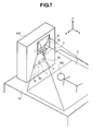
- Figs. 7 , 8 and 9 are views for explaining the projection type display apparatus, in particular, in the case where the reflection mirror 35 is disposed between the first lens group 2 and the second lens group 3.
- the optical axis of the first lens group 2 is bent by about 90 degree to the optical axis of the second lens group 3.
- the angle defined between the optical axis 8c of the light source 8 and the optical axis 3c of the second lens group 3 becomes nearly vertical.
- Figs. 10 and 11 attached herewith and further tables 1 to 4 below, while showing the detailed numerical values of the optical elements, including the lens optic system and the reflection optic system therein.
- Figs. 8 and 9 attached herewith are diagrams for showing light beams in the optic system according to the present invention, upon basis of an example of first numerical values.
- Fig. 10 shows the Y-Z cross-section
- Fig. 11 shows X-Z cross-section.
- the light emitted from the image display element 1 shown at the left-hand side in Fig. 10 firstly passes through the first lens group 2 built up with only lenses, each having only surfaces that are rotationally symmetric, among the lens optic system including the plural number of lenses therein. Then, it passes through the second lens group 3 including the free curved surface lens that is rotationally asymmetric, and is reflected upon the reflection surface of the free curved surface mirror 4 within the reflection optic system. Thereafter, the reflecting light thereupon is incident upon the screen 5.
- the first lens group 2 of the lens optic system is built up with the plural number of lenses, all of which have a refracting interface of rotationally symmetric configuration, and four (4) of the refracting interfaces of those lenses have aspheric surfaces, each being rotationally symmetric, and others have the spherical surfaces.
- the aspheric surface being rotationally symmetric, which is used therein, can be expressed by the following equation (Eq.
- Z cr 2 1 + 1 - 1 + k ⁇ c 2 ⁇ r 2 + A ⁇ r 4 + B ⁇ r 6 + C ⁇ r 8 + D ⁇ r 10 + E ⁇ r 12 + F ⁇ r 14 + G ⁇ r 16 + H ⁇ r 18 + J ⁇ r 20
- Z represents an amount of sag of the free curved surface configuration, in particular, into the direction perpendicular to X- and Y-axes, "c” the curvature at the apex, “r” the distance from the origin within a plane of X- and Y-axes, "k” the conical constant, and C(m,n) the coefficients of the polynomials.
- the following table 1 shows the numerical data of the optic system, according to the embodiment 1.
- S0 to S23 correspond to the marks S0 to S23 shown in Fig. 5 mentioned above, respectively.
- the mark S0 shows the display surface of the image display element 11, i.e., the object surface, and S23 the reflection surface of the freely curved surface mirror 5.
- a mark S24 shows an incident surface of the projection image or screen 5 shown in Fig. 2 mentioned above, i.e., the image surface.
- Rd is the radius of curvature for each surface, and it is presented by a positive value in case when having a center of curvature on the left-hand side of the surface in Fig. 3 mentioned above, while by a negative value in case when having it on the right-hand side, contrary to the above.
- TH is the distance between the surfaces, i.e., presenting the distance from the apex of the lens surface to the apex of the next lens surface. The distance between the surfaces is presented by a positive value in case when the next lens surface is at the left-hand side, while by a negative value in case when it is at the right-hand side, with respect to that lens surface.
- S5, S6, S17 and S18 are aspheric surfaces, being rotationally symmetric, and also in this table 1, they are attached with "*" beside the surface numbers for easy understanding thereof, wherein coefficients of the aspheric surface of those four (4) surfaces are shown in the table 2 below.
- S19 to S22 in the table 1 mentioned above are the refraction surfaces, each having the free curved surface configuration, which builds up the second lens group of the lens optic system mentioned above, and S23 is the reflection surface having the free curved surface configuration S23 of the reflection optic system, wherein they are shown by attaching "#" beside the surface numbers thereof. Values of the coefficients for presenting the configurations of those five (5) free curved surfaces are shown in the table 3 below.
- the object surface i.e., the display screen of the image display element 1 is inclined by -1.163 degrees to the optical axis of the lens optic system mentioned above.
- a positive value presents the direction, in which the normal line on the object surface rotates into the clockwise direction within the cross-section shown this Fig. 6 .
- the free curved surface mirror 4 shown by the mark S23 in Fig. 5 or 6 mentioned above is so disposed that, the normal line at the origin of the local coordinates thereof, i.e., the Z-axis is inclined by around +29 degree from the position in parallel with the optical axis of the lens optic system mentioned above while positioning that origin of the local coordinates on the optical axis of the lens optic system mentioned above.
- the direction of this inclination is assumed to be positive in the anti-clockwise rotating direction, within the cross-sections shown in Fig. 5 or 6 , similar to that of the object surface mentioned above, and therefore, it is inclined into the anti-clockwise rotation.
- the light at the center of the screen emitting from the center on the screen of the image display element 1 and propagating almost along the optical axis of the lens optic system mentioned above, after reflection upon S23, it propagates into a direction inclined by 58 degrees, i.e., 2 times large as the inclination angle with respect to the optical axis of the lens optic system mentioned above (see an arrow in the figure).
- the conditions of the inclination and an offset of the local coordinates are shown in the table 4 below, on each of the surfaces.
- values of the inclination angle and the offset are shown on the columns on the right-hand sides of the surface number, wherein "ADE” is a magnitude of the inclination within the surface in parallel with the cross-section of Fig. 5 , and a rule of display thereof is as mentioned above.
- "YDE” is a magnitude of the offset, and the offset is set up into the direction perpendicular to the optical axis within the surface in parallel with the cross-section of Fig. 5 , and the offset below on the cross-section of Fig. 5 is assumed to be positive.
Applications Claiming Priority (2)
| Application Number | Priority Date | Filing Date | Title |
|---|---|---|---|
| JP2007046386A JP5125147B2 (ja) | 2007-02-27 | 2007-02-27 | 投射型表示装置 |
| EP08250355A EP1965254B1 (fr) | 2007-02-27 | 2008-01-30 | Appareil d'affichage de type projection |
Related Parent Applications (2)
| Application Number | Title | Priority Date | Filing Date |
|---|---|---|---|
| EP08250355A Division EP1965254B1 (fr) | 2007-02-27 | 2008-01-30 | Appareil d'affichage de type projection |
| EP08250355.8 Division | 2008-01-30 |
Publications (2)
| Publication Number | Publication Date |
|---|---|
| EP2284608A1 true EP2284608A1 (fr) | 2011-02-16 |
| EP2284608B1 EP2284608B1 (fr) | 2014-04-16 |
Family
ID=39539744
Family Applications (2)
| Application Number | Title | Priority Date | Filing Date |
|---|---|---|---|
| EP10013410.5A Active EP2284608B1 (fr) | 2007-02-27 | 2008-01-30 | Appareil d'affichage de type projection |
| EP08250355A Active EP1965254B1 (fr) | 2007-02-27 | 2008-01-30 | Appareil d'affichage de type projection |
Family Applications After (1)
| Application Number | Title | Priority Date | Filing Date |
|---|---|---|---|
| EP08250355A Active EP1965254B1 (fr) | 2007-02-27 | 2008-01-30 | Appareil d'affichage de type projection |
Country Status (4)
| Country | Link |
|---|---|
| US (3) | US7896507B2 (fr) |
| EP (2) | EP2284608B1 (fr) |
| JP (1) | JP5125147B2 (fr) |
| CN (2) | CN102087463A (fr) |
Families Citing this family (33)
| Publication number | Priority date | Publication date | Assignee | Title |
|---|---|---|---|---|
| JP5125147B2 (ja) * | 2007-02-27 | 2013-01-23 | 株式会社日立製作所 | 投射型表示装置 |
| JP2010002885A (ja) * | 2008-05-22 | 2010-01-07 | Sanyo Electric Co Ltd | 投写型映像表示装置 |
| TW201017315A (en) | 2008-10-28 | 2010-05-01 | Coretronic Corp | Projection apparatus |
| JP2010237347A (ja) | 2009-03-31 | 2010-10-21 | Hitachi Ltd | 投射型表示装置 |
| JP5381377B2 (ja) * | 2009-06-18 | 2014-01-08 | セイコーエプソン株式会社 | プロジェクター |
| TWI420136B (zh) | 2009-07-03 | 2013-12-21 | Young Optics Inc | 定焦鏡頭及成像系統 |
| CN102043310B (zh) * | 2009-10-13 | 2014-08-27 | 中强光电股份有限公司 | 投影系统、投影装置及成像模组 |
| JP5504833B2 (ja) * | 2009-11-11 | 2014-05-28 | 株式会社ニコン | プロジェクタ |
| JP5816282B2 (ja) * | 2010-07-30 | 2015-11-18 | ケーエルエー−テンカー コーポレイション | 環形光照明器、ビーム整形器及び照明方法 |
| JP5287828B2 (ja) * | 2010-10-26 | 2013-09-11 | 株式会社デンソー | ヘッドアップディスプレイ装置 |
| JP5834622B2 (ja) * | 2011-08-25 | 2015-12-24 | 株式会社ニコン | 映像投写装置用光学系および映像投写装置 |
| JP5686255B2 (ja) * | 2011-08-30 | 2015-03-18 | 株式会社リコー | プロジェクタ装置 |
| JP5686256B2 (ja) * | 2011-08-30 | 2015-03-18 | 株式会社リコー | プロジェクタ装置 |
| JP5669020B2 (ja) * | 2011-09-16 | 2015-02-12 | 株式会社リコー | 画像投影装置 |
| CN102385234B (zh) * | 2011-10-27 | 2013-07-24 | 海信集团有限公司 | 壁挂式投影机 |
| CN102591114A (zh) * | 2012-03-31 | 2012-07-18 | 海信集团有限公司 | 壁挂式投影装置 |
| CN102636948A (zh) * | 2012-05-04 | 2012-08-15 | 海信集团有限公司 | 壁挂式投影装置 |
| US20140218695A1 (en) * | 2013-02-01 | 2014-08-07 | 3M Innovative Properties Company | Orthogonally disposed projection surfaces |
| CN105339842B (zh) | 2013-06-28 | 2017-03-08 | 日立麦克赛尔株式会社 | 投影型影像显示装置 |
| US9891508B2 (en) | 2013-09-13 | 2018-02-13 | Hitachi Maxell, Ltd. | Projection-type image display device |
| US20150109536A1 (en) * | 2013-10-17 | 2015-04-23 | Delta Electronics, Inc. | Display apparatus and display method using the same |
| JP6471424B2 (ja) * | 2013-11-13 | 2019-02-20 | セイコーエプソン株式会社 | プロジェクター |
| JP5804119B2 (ja) * | 2014-03-27 | 2015-11-04 | セイコーエプソン株式会社 | プロジェクター |
| CN104954768A (zh) * | 2014-03-28 | 2015-09-30 | 联想(北京)有限公司 | 一种投影图像矫正方法及电子设备 |
| JP6321148B2 (ja) | 2014-05-09 | 2018-05-09 | マクセル株式会社 | 投写型映像表示装置 |
| JP6225964B2 (ja) * | 2015-09-03 | 2017-11-08 | セイコーエプソン株式会社 | プロジェクター及び表示システム |
| CN105068363A (zh) * | 2015-09-15 | 2015-11-18 | 周光磊 | 一种桌面超短焦光学模组 |
| JP6284057B2 (ja) * | 2016-09-13 | 2018-02-28 | 株式会社リコー | 画像投影装置 |
| JP6593462B2 (ja) * | 2018-01-12 | 2019-10-23 | 株式会社Jvcケンウッド | 虚像表示装置 |
| CN108761811A (zh) * | 2018-04-27 | 2018-11-06 | 盐城易快来科技有限公司 | 一种3d图像显示处理装置及处理方法 |
| CN110286468A (zh) * | 2019-06-28 | 2019-09-27 | 沂普光电(天津)有限公司 | 一种小体积超短焦投影系统 |
| EP4001987A1 (fr) * | 2020-11-18 | 2022-05-25 | Coretronic Corporation | Système d'imagerie et dispositif de projection |
| CN115202137A (zh) * | 2022-07-20 | 2022-10-18 | Oppo广东移动通信有限公司 | 投影光学系统、投影光学模组及电子设备 |
Citations (8)
| Publication number | Priority date | Publication date | Assignee | Title |
|---|---|---|---|---|
| JPH05134213A (ja) | 1991-11-08 | 1993-05-28 | Canon Inc | 付加光学系を有した投影装置 |
| JPH08251524A (ja) * | 1995-03-09 | 1996-09-27 | Fujitsu General Ltd | 背面投写型表示装置 |
| US20020021418A1 (en) * | 2000-08-17 | 2002-02-21 | Mitsubishi Electric Research Laboratories, Inc. | Automatic keystone correction for projectors with arbitrary orientation |
| JP2003005278A (ja) * | 2001-06-20 | 2003-01-08 | Fujitsu General Ltd | 液晶プロジェクタ |
| JP2003029210A (ja) * | 2001-07-13 | 2003-01-29 | Nikon Corp | 背面投射型表示装置 |
| WO2006098402A1 (fr) * | 2005-03-17 | 2006-09-21 | Brother Kogyo Kabushiki Kaisha | Projecteur |
| US20060227432A1 (en) * | 2005-04-08 | 2006-10-12 | Hiroki Yoshikawa | Projecting optical unit and projecting type image display apparatus therewith |
| US20060238718A1 (en) * | 2005-04-22 | 2006-10-26 | Erickson David L | Image rotator |
Family Cites Families (15)
| Publication number | Priority date | Publication date | Assignee | Title |
|---|---|---|---|---|
| US5648871A (en) | 1991-06-28 | 1997-07-15 | Canon Kabushiki Kaisha | Projection apparatus utilizing an anamorphic optical system |
| JP4196815B2 (ja) * | 2003-11-28 | 2008-12-17 | 株式会社日立製作所 | 背面投写型映像表示装置 |
| US7677738B2 (en) * | 2004-04-27 | 2010-03-16 | Mitsubishi Electric Corporation | Image projector |
| JP2006084989A (ja) * | 2004-09-17 | 2006-03-30 | Canon Inc | 投射光学系及び投射装置 |
| JP2006138882A (ja) | 2004-11-10 | 2006-06-01 | Konica Minolta Opto Inc | 斜め投影光学系 |
| JP2006154041A (ja) | 2004-11-26 | 2006-06-15 | Konica Minolta Opto Inc | プロジェクション光学系 |
| JP2006279581A (ja) * | 2005-03-29 | 2006-10-12 | Seiko Epson Corp | プロジェクタ |
| JP5114828B2 (ja) * | 2005-04-08 | 2013-01-09 | 株式会社日立製作所 | 投写光学ユニット |
| JP2007011248A (ja) * | 2005-05-31 | 2007-01-18 | Victor Co Of Japan Ltd | 投射型表示装置 |
| JP2007010787A (ja) * | 2005-06-28 | 2007-01-18 | Sony Corp | プロジェクタ、映像表示装置およびプロジェクションシステム |
| JP5134213B2 (ja) | 2006-06-13 | 2013-01-30 | 株式会社田中化学研究所 | アルカリ電池用正極活物質 |
| JP2008134350A (ja) * | 2006-11-27 | 2008-06-12 | Hitachi Ltd | 映像投写装置 |
| JP5125147B2 (ja) * | 2007-02-27 | 2013-01-23 | 株式会社日立製作所 | 投射型表示装置 |
| JP4901595B2 (ja) * | 2007-03-06 | 2012-03-21 | 三洋電機株式会社 | 投写型表示装置 |
| CN102081288A (zh) * | 2009-11-30 | 2011-06-01 | 三洋电机株式会社 | 投射型影像显示装置 |
-
2007
- 2007-02-27 JP JP2007046386A patent/JP5125147B2/ja active Active
-
2008
- 2008-01-09 CN CN2010105893866A patent/CN102087463A/zh active Pending
- 2008-01-09 CN CNA2008100020423A patent/CN101256274A/zh active Pending
- 2008-01-30 EP EP10013410.5A patent/EP2284608B1/fr active Active
- 2008-01-30 EP EP08250355A patent/EP1965254B1/fr active Active
- 2008-01-31 US US12/023,151 patent/US7896507B2/en active Active
-
2010
- 2010-10-08 US US12/900,554 patent/US8403504B2/en active Active
-
2013
- 2013-02-22 US US13/773,677 patent/US8573787B2/en active Active
Patent Citations (8)
| Publication number | Priority date | Publication date | Assignee | Title |
|---|---|---|---|---|
| JPH05134213A (ja) | 1991-11-08 | 1993-05-28 | Canon Inc | 付加光学系を有した投影装置 |
| JPH08251524A (ja) * | 1995-03-09 | 1996-09-27 | Fujitsu General Ltd | 背面投写型表示装置 |
| US20020021418A1 (en) * | 2000-08-17 | 2002-02-21 | Mitsubishi Electric Research Laboratories, Inc. | Automatic keystone correction for projectors with arbitrary orientation |
| JP2003005278A (ja) * | 2001-06-20 | 2003-01-08 | Fujitsu General Ltd | 液晶プロジェクタ |
| JP2003029210A (ja) * | 2001-07-13 | 2003-01-29 | Nikon Corp | 背面投射型表示装置 |
| WO2006098402A1 (fr) * | 2005-03-17 | 2006-09-21 | Brother Kogyo Kabushiki Kaisha | Projecteur |
| US20060227432A1 (en) * | 2005-04-08 | 2006-10-12 | Hiroki Yoshikawa | Projecting optical unit and projecting type image display apparatus therewith |
| US20060238718A1 (en) * | 2005-04-22 | 2006-10-26 | Erickson David L | Image rotator |
Also Published As
| Publication number | Publication date |
|---|---|
| US8403504B2 (en) | 2013-03-26 |
| US20080204673A1 (en) | 2008-08-28 |
| EP1965254A1 (fr) | 2008-09-03 |
| CN101256274A (zh) | 2008-09-03 |
| US8573787B2 (en) | 2013-11-05 |
| US20110025991A1 (en) | 2011-02-03 |
| EP1965254B1 (fr) | 2013-04-03 |
| US20130162961A1 (en) | 2013-06-27 |
| CN102087463A (zh) | 2011-06-08 |
| JP2008209670A (ja) | 2008-09-11 |
| JP5125147B2 (ja) | 2013-01-23 |
| US7896507B2 (en) | 2011-03-01 |
| EP2284608B1 (fr) | 2014-04-16 |
Similar Documents
| Publication | Publication Date | Title |
|---|---|---|
| EP2284608B1 (fr) | Appareil d'affichage de type projection | |
| EP1868032B1 (fr) | Appareil d'affichage d'images par projection | |
| EP1868031B1 (fr) | Appareil d'affichage d'images par projection | |
| EP1925960A2 (fr) | Appareil de projection d'images | |
| JP4890771B2 (ja) | 投写光学系およびこれを用いた投写型表示装置 | |
| US7009765B2 (en) | Wide angle lens system having a distorted intermediate image | |
| US7896504B2 (en) | Projection module and projector incorporating same | |
| US7789516B2 (en) | Projection type image display device | |
| US20080192208A1 (en) | Projection System | |
| CN101140353A (zh) | 投影光学单元和用它的投影型图像显示装置 | |
| JP2006154041A (ja) | プロジェクション光学系 | |
| JP2004061959A (ja) | 投射光学系、投射型画像表示装置および画像表示システム | |
| JP2908570B2 (ja) | 外付けレンズおよび画像投射装置 |
Legal Events
| Date | Code | Title | Description |
|---|---|---|---|
| PUAI | Public reference made under article 153(3) epc to a published international application that has entered the european phase |
Free format text: ORIGINAL CODE: 0009012 |
|
| 17P | Request for examination filed |
Effective date: 20101025 |
|
| AC | Divisional application: reference to earlier application |
Ref document number: 1965254 Country of ref document: EP Kind code of ref document: P |
|
| AK | Designated contracting states |
Kind code of ref document: A1 Designated state(s): DE FR GB |
|
| AX | Request for extension of the european patent |
Extension state: AL BA MK RS |
|
| 17Q | First examination report despatched |
Effective date: 20120917 |
|
| RAP1 | Party data changed (applicant data changed or rights of an application transferred) |
Owner name: HITACHI CONSUMER ELECTRONICS CO., LTD. |
|
| GRAP | Despatch of communication of intention to grant a patent |
Free format text: ORIGINAL CODE: EPIDOSNIGR1 |
|
| INTG | Intention to grant announced |
Effective date: 20131112 |
|
| GRAS | Grant fee paid |
Free format text: ORIGINAL CODE: EPIDOSNIGR3 |
|
| GRAA | (expected) grant |
Free format text: ORIGINAL CODE: 0009210 |
|
| AC | Divisional application: reference to earlier application |
Ref document number: 1965254 Country of ref document: EP Kind code of ref document: P |
|
| AK | Designated contracting states |
Kind code of ref document: B1 Designated state(s): DE FR GB |
|
| REG | Reference to a national code |
Ref country code: GB Ref legal event code: FG4D |
|
| REG | Reference to a national code |
Ref country code: DE Ref legal event code: R096 Ref document number: 602008031624 Country of ref document: DE Effective date: 20140605 |
|
| REG | Reference to a national code |
Ref country code: DE Ref legal event code: R097 Ref document number: 602008031624 Country of ref document: DE |
|
| PLBE | No opposition filed within time limit |
Free format text: ORIGINAL CODE: 0009261 |
|
| STAA | Information on the status of an ep patent application or granted ep patent |
Free format text: STATUS: NO OPPOSITION FILED WITHIN TIME LIMIT |
|
| REG | Reference to a national code |
Ref country code: DE Ref legal event code: R082 Ref document number: 602008031624 Country of ref document: DE Representative=s name: MEWBURN ELLIS LLP, GB |
|
| 26N | No opposition filed |
Effective date: 20150119 |
|
| REG | Reference to a national code |
Ref country code: GB Ref legal event code: 732E Free format text: REGISTERED BETWEEN 20150312 AND 20150318 |
|
| REG | Reference to a national code |
Ref country code: DE Ref legal event code: R081 Ref document number: 602008031624 Country of ref document: DE Owner name: HITACHI MAXELL, LTD., IBARAKI-SHI, JP Free format text: FORMER OWNER: HITACHI CONSUMER ELECTRONICS CO., LTD., TOKIO/TOKYO, JP Effective date: 20150317 Ref country code: DE Ref legal event code: R082 Ref document number: 602008031624 Country of ref document: DE Representative=s name: MEWBURN ELLIS LLP, GB Effective date: 20150317 Ref country code: DE Ref legal event code: R081 Ref document number: 602008031624 Country of ref document: DE Owner name: MAXELL, LTD., OYAMAZAKI, JP Free format text: FORMER OWNER: HITACHI CONSUMER ELECTRONICS CO., LTD., TOKIO/TOKYO, JP Effective date: 20150317 |
|
| REG | Reference to a national code |
Ref country code: DE Ref legal event code: R097 Ref document number: 602008031624 Country of ref document: DE Effective date: 20150119 |
|
| REG | Reference to a national code |
Ref country code: FR Ref legal event code: TP Owner name: HITACHI MAXELL LTD., JP Effective date: 20150504 |
|
| REG | Reference to a national code |
Ref country code: FR Ref legal event code: PLFP Year of fee payment: 9 |
|
| REG | Reference to a national code |
Ref country code: FR Ref legal event code: PLFP Year of fee payment: 10 |
|
| REG | Reference to a national code |
Ref country code: FR Ref legal event code: PLFP Year of fee payment: 11 |
|
| REG | Reference to a national code |
Ref country code: DE Ref legal event code: R082 Ref document number: 602008031624 Country of ref document: DE Representative=s name: MEWBURN ELLIS LLP, DE Ref country code: DE Ref legal event code: R082 Ref document number: 602008031624 Country of ref document: DE Representative=s name: MEWBURN ELLIS LLP, GB Ref country code: DE Ref legal event code: R081 Ref document number: 602008031624 Country of ref document: DE Owner name: MAXELL, LTD., OYAMAZAKI, JP Free format text: FORMER OWNER: HITACHI MAXELL, LTD., IBARAKI-SHI, OSAKA, JP |
|
| REG | Reference to a national code |
Ref country code: FR Ref legal event code: TP Owner name: MAXELL LTD, JP Effective date: 20180329 |
|
| REG | Reference to a national code |
Ref country code: DE Ref legal event code: R082 Ref document number: 602008031624 Country of ref document: DE Representative=s name: MEWBURN ELLIS LLP, DE |
|
| REG | Reference to a national code |
Ref country code: DE Ref legal event code: R081 Ref document number: 602008031624 Country of ref document: DE Owner name: MAXELL, LTD., OYAMAZAKI, JP Free format text: FORMER OWNER: MAXELL, LTD., OYAMAZAKI, KYOTO, JP |
|
| REG | Reference to a national code |
Ref country code: DE Ref legal event code: R081 Ref document number: 602008031624 Country of ref document: DE Owner name: MAXELL, LTD., OYAMAZAKI, JP Free format text: FORMER OWNER: MAXELL HOLDINGS, LTD., OYAMAZAKI, KYOTO, JP |
|
| PGFP | Annual fee paid to national office [announced via postgrant information from national office to epo] |
Ref country code: FR Payment date: 20230124 Year of fee payment: 16 |
|
| PGFP | Annual fee paid to national office [announced via postgrant information from national office to epo] |
Ref country code: DE Payment date: 20240119 Year of fee payment: 17 Ref country code: GB Payment date: 20240119 Year of fee payment: 17 |