EP2280845B1 - Système de ferrures pour un siège automobile - Google Patents
Système de ferrures pour un siège automobile Download PDFInfo
- Publication number
- EP2280845B1 EP2280845B1 EP09753654.4A EP09753654A EP2280845B1 EP 2280845 B1 EP2280845 B1 EP 2280845B1 EP 09753654 A EP09753654 A EP 09753654A EP 2280845 B1 EP2280845 B1 EP 2280845B1
- Authority
- EP
- European Patent Office
- Prior art keywords
- fitting
- driver
- transmission element
- lever
- fitting system
- Prior art date
- Legal status (The legal status is an assumption and is not a legal conclusion. Google has not performed a legal analysis and makes no representation as to the accuracy of the status listed.)
- Active
Links
Images


Classifications
-
- B—PERFORMING OPERATIONS; TRANSPORTING
- B60—VEHICLES IN GENERAL
- B60N—SEATS SPECIALLY ADAPTED FOR VEHICLES; VEHICLE PASSENGER ACCOMMODATION NOT OTHERWISE PROVIDED FOR
- B60N2/00—Seats specially adapted for vehicles; Arrangement or mounting of seats in vehicles
- B60N2/02—Seats specially adapted for vehicles; Arrangement or mounting of seats in vehicles the seat or part thereof being movable, e.g. adjustable
- B60N2/22—Seats specially adapted for vehicles; Arrangement or mounting of seats in vehicles the seat or part thereof being movable, e.g. adjustable the back-rest being adjustable
- B60N2/235—Seats specially adapted for vehicles; Arrangement or mounting of seats in vehicles the seat or part thereof being movable, e.g. adjustable the back-rest being adjustable by gear-pawl type mechanisms
- B60N2/2356—Seats specially adapted for vehicles; Arrangement or mounting of seats in vehicles the seat or part thereof being movable, e.g. adjustable the back-rest being adjustable by gear-pawl type mechanisms with internal pawls
- B60N2/2358—Seats specially adapted for vehicles; Arrangement or mounting of seats in vehicles the seat or part thereof being movable, e.g. adjustable the back-rest being adjustable by gear-pawl type mechanisms with internal pawls and provided with memory locks
-
- B—PERFORMING OPERATIONS; TRANSPORTING
- B60—VEHICLES IN GENERAL
- B60N—SEATS SPECIALLY ADAPTED FOR VEHICLES; VEHICLE PASSENGER ACCOMMODATION NOT OTHERWISE PROVIDED FOR
- B60N2/00—Seats specially adapted for vehicles; Arrangement or mounting of seats in vehicles
- B60N2/02—Seats specially adapted for vehicles; Arrangement or mounting of seats in vehicles the seat or part thereof being movable, e.g. adjustable
- B60N2/20—Seats specially adapted for vehicles; Arrangement or mounting of seats in vehicles the seat or part thereof being movable, e.g. adjustable the back-rest being tiltable, e.g. to permit easy access
-
- B—PERFORMING OPERATIONS; TRANSPORTING
- B60—VEHICLES IN GENERAL
- B60N—SEATS SPECIALLY ADAPTED FOR VEHICLES; VEHICLE PASSENGER ACCOMMODATION NOT OTHERWISE PROVIDED FOR
- B60N2205/00—General mechanical or structural details
- B60N2205/50—Interlocking shaft arrangements transmitting movement between hinge mechanisms on both sides of a seat
Definitions
- the invention relates to a fitting system for a vehicle seat having the features of the preamble of claim 1.
- a fitting system of this kind is, from the DE 198 31 581 A1 known, the second fitting also serves as a free-pivoting device.
- a fitting system with a first fitting, a second fitting and a transmission element between the two fittings is known.
- Each fitting has a shaft piece whose rotation unlocks the fitting.
- the shaft piece is rotated by means of a first operating element on the second fitting and a rotatably mounted thereon first lever is pivoted.
- the first lever takes with a second lever, which is rotatably connected to the transmission element.
- the pivoting second lever rotates the transmission element, which transmits the rotational movement to the shaft piece of the first fitting.
- For free pivoting of the back of the second fitting is associated with an additional free-pivoting device which is locked by means of a pivoting pawl.
- the pawl By means of a second control element, the pawl is opened, wherein the swiveling pawl pivots the second lever by means of a cable.
- the pivoting second lever rotates the transmission element, which transmits the rotational movement to the shaft piece of the first fitting.
- the first fitting unlocks while the second fitting remains locked.
- the invention is based on the object to improve a fitting system of the type mentioned, in particular easier and cheaper to design. This object is achieved by a fitting system with the features of claim 1.
- Advantageous embodiments are the subject of the dependent claims.
- the transmission element - coupled to driving - receives By the driver of the first fitting the transmission element - coupled to driving - receives, wherein between the driver and the transmission element in a rotational direction an idle path is provided, a simple decoupling is available. Overall, less space is required, and the structure of the fitting system is simplified. The free travel is greater than the time required to unlock the first fitting Entriegelungsweg the driver, so that the decoupling is complete. When swiveling free, the second fitting remains locked and stores the previously set inclination (memory function).
- the fitting system according to the invention is intended for a vehicle seat, the backrest tilt adjustable and memorized free to be pivotable, but at the same time should have reduced production costs, which is achieved by using only a single free-pivoting device in the fitting system.
- the free travel ie the decoupling, realized by a spline between the transmission element and the driver, wherein in the initial position, the longitudinal ribs of the transmission element and the edges of the hub receptacle of the driver are spaced apart in a rotational direction.
- the transmission element and / or the driver have a profile with threefold symmetry. Such a profile is for example in the DE 10 2006 041 917 B3 described.
- the free travel according to the invention is significantly larger than a conventional game, which is provided for the purpose of tolerance compensation.
- the actuation of the driver in decoupling from the transmission element is preferably carried out by means of a lever member which rotatable relative to the transmission element and rotatably connected to the driver, in particular clipped, is.
- the lever element arranged outside the first fitting has a larger radial dimension than the transmission element, in particular it encloses the transmission element.
- the second operating element preferably acts by means of an unlocking lever on the lever element, in particular by means of a cable, which is provided on the one hand on the release lever and on the other hand is in operative connection with the second control element.
- the second operating element is also in operative connection with the free-pivoting device by means of a further cable pull, wherein the two said cable pulls can be in series or parallel to one another.
- a further cable pull for the non-rotatable connection of the lever member to the driver and / or the release lever another spline shaft profile may be provided.
- the fitting system according to the invention is preferably designed so that upon actuation of the first control element, the transmission element rotates and immediately rotates the driver of the first fitting (as well as those of the second fitting rotates), whereby with the unlocked fittings a tilt adjustment is possible while pressing the second Operating element, the transmission element remains untwisted and the second control element rotates the driver of the first fitting, which with the unlocked first fitting and the unlocked free-pivoting device, a free pivoting of the backrest is possible.
- a vehicle seat 1 which is presently provided as the front seat of a motor vehicle, has a seat part 3 and a backrest 4.
- the back 4 is adjustable on the one hand in its inclination relative to the seat part 3, whereby more use positions are defined, and on the other hand freely swingable, i. pivoted forward in a non-use position, for example, to facilitate access to a rear row of seats.
- the fitting system 5 has on each vehicle seat side a fitting, which are constructed and coupled in the manner described below.
- a first fitting 10 which is designed as a latching fitting, has a first fitting part 11 and a second fitting part 12, which is rotatable about an axis A relative to the first fitting part 11.
- Axis A defines a subsequently used Cylinder Corridor System.
- the fitting parts 11 and 12 are both disc-shaped and are held together in the axial direction by a Umklamm ceremoniessring 13 which is fixedly connected to the first fitting part 11 and the second fitting part 12 with the interposition of a damper ring 13 a radially overlaps.
- the first fitting 10 therefore forms a disk-shaped unit in terms of construction.
- the first fitting part 11 has a plurality, in this case four, axially projecting guide and bearing segments 11 a, on the one hand on its radially outwardly facing, cylindrically curved surface store the second fitting part 12 and on the other hand in pairs between at least one bar 14, in this case a total of two Latch 14, movable in the radial direction.
- the second fitting part 12 has - as an internally toothed peripheral boundary surface of a cup-like depression - a ring gear 12a, by means of which the second fitting part 12 on the one hand on the guide and bearing segments 11a and on the other hand cooperates with the externally toothed bars 14 to the first fitting 10 to lock.
- an eccentric 16 biased by springs 15 is provided, which is arranged rotatably about the axis A in the middle between the guide and bearing segments 11a.
- a control disk 17 is provided, which is arranged axially between the guide and bearing segments 11 a and the second fitting part 12 , The control plate 17 cooperates with the bars 14, in this case by axially projecting lugs of the bolt 14 engage in scenes of the control disk 17.
- the control disk 17 is non-rotatably mounted on the eccentric 16, which is rotatable by means of a driver 18 - counter to the force of the springs 15 - could also sit directly on the driver 18 in a modified form.
- the driver 18, which is rotatably mounted about the axis A, the control disk 17 by a length of the gate corresponding angle, in this case about 30 °, rotate.
- the preferably made of plastic driver 18 is - in this case from the second fitting part 12 facing away from the first fitting part 11 ago - by central openings of the two fitting parts 11 and 12, which also serve its storage, and - coupled with driving - by the eccentric 16th inserted and is in the axial direction by a retaining ring 19th secured, which is arranged on the side facing away from the first fitting part 11 end face of the second fitting part 12 and which - preferably formed of plastic - is preferably clipped onto the driver 18.
- a fitting lower part 5a fastened to the first fitting part 11 connects the first fitting 10 to the seat part, while a fitting upper part 5b attached to the second fitting part 12 connects the first fitting 10 to the backrest 4.
- a second fitting 20 on the opposite side of the vehicle seat also has the components described above, and the first fitting part 21 is attached to the fitting base 5a, but the fitting upper part 5b is rotatably mounted on the second fitting 20, preferably on the second fitting part 22, and with the second Fitting 22 lockable.
- a locking device and the modification of the fitting upper part 5b and optionally the second fitting part 22 a second fitting 20 associated free-pivoting device 24 is defined.
- the basic structure of such a free-pivoting device 24 is for example from the DE 10 2006 044 490 A 1 known for a geared fitting.
- An annular latching element 24a on the second fitting part 22 serves for the pivotable mounting of the fitting upper part 5b.
- the latching element 24a for example, a collar on which the fitting upper part 5b is pivotally mounted with a bearing opening, which may also be formed in the manner of a collar.
- the latching element 24a is connected directly or indirectly to the second fitting part 22, for example by means of a laser weld (or in another way).
- An annular fixing disk which engages over the fitting upper part 5b in the bearing area, can be fixedly connected to the latching element 24a and optionally to the second fitting part 22 for axial securing of the latter. There is a certain clearance in the radial direction.
- the fitting upper part 5b may consist of two parts fastened to one another, one of which is mounted on the latching element 24a and the other is connected as an adapter to the backrest 4.
- a pawl 24b is pivotally mounted on the upper fitting part 5b on the side facing the latching element 24a by means of a bearing pin, hereinafter referred to as pawl bearing pin 24bb.
- a bearing pin hereinafter referred to as pawl bearing pin 24bb.
- the pawl bearing pin 24bb is formed as an eccentric pin, i. it is rotatably mounted about a pivot axis of the pawl 24b offset axis in the fitting upper part 5b relative to this.
- To compensate for manufacturing tolerances of the pawl bearing pin 24bb is set and fixed so that the pawl 24b with a maximum latch engagement clearance against the locking stop of the locking element 24a, but outside the angular range of the self-locking.
- a clamping element 24c and a catch element 24d are provided as securing elements.
- Par allel to the pawl bearing pin 24bb is an unlocking shaft 24e by means of a bearing bush 24ee rotatably mounted in the fitting upper part 5b.
- the clamping element 24c and rotatably the catch element 24d are pivotable about the common axis defined by the unlocking shaft 24e and aligned with the catch 24b when the fitting upper part 5b is locked.
- the operation of catch element 24d and clamping element 24c is in the DE 44 39 644 A1 described.
- the clamping element 24c rests with an eccentric to the unlocking shaft 24e curved clamping surface at an angle outside the self-locking portion of a contact surface of the pawl 24b.
- the clamping element 24c is biased by a tension spring 24cc designed as a spiral spring, so that it acts on the pawl 24b (and biases it against the latching stop of the latching element 25a).
- the catch element 24d is acted upon by a catch spring 24dd designed as a helical tension spring and lies against a catch spring Stop the fitting upper part 5b.
- the pawl 24b is held in position by the tensioning element 24c, and the catching element 24d is arranged at a small distance from the pawl 24b.
- the clamping element 24c can open because of the lack of self-locking. After a slight pivoting movement of the pawl 24b this comes into abutment against the catch element 24d.
- the catch element 24d then supports the pawl 24b, which rests against the catch element 24d within the self-locking region, preferably tangentially or concentrically and as extensively as possible. This prevents the pawl 24b from opening (further).
- the catching element 24d and the tensioning element 24c are coupled with each other by means of a slot-pin guide with a free travel on entrainment.
- the tensioning element 24c has a slot curved around the unlocking shaft 24e, into which a pin of the catching element 24d engages.
- a lid 24f attached to the fitting upper 5b covers the pawl 24b including the pawl bearing pin 24bb, the catching member 24d, the tensioning member 24c, and the springs 24cc and 24dd, and protects them from contamination.
- the fitting upper part 5b at least one, in this case two diagonally relative to the axis A opposite first stop cam 24g and the locking element 24a in the same number and corresponding arrangement second stop cam 24h.
- Each first stop cam 24g which has a first stop face pointing in the rearward pivoting direction, cooperates with exactly one second stop cam 24h, which has a second stop face pointing in the forward pivoting direction.
- the pairs distributed in the circumferential direction stop cams 24g and 24h are arranged radially spaced from the axis A, formed by an axial, facing each other exhibition in the material in tongue form and facing with its at the free end of the tongues end faces abutment surfaces in the circumferential direction facing each other.
- the stop cams 24g and 24h are only axially present, i. they are arranged radially inside the outer edge of the associated component.
- the stop cams 24g and 24h are issued so that they protrude as much as possible with their stop surfaces in the preferably existing gap between fitting upper part 5b and locking element 24a.
- the exhibitions have the effect of creating a depression in the material on the respective back.
- the abutment surfaces extend in the axial and radial directions, i. without a component in the circumferential direction, so that they can transmit the forces optimally in the case of a system.
- the stop formed by the stop cams 24g and 24h limiting the pivotal movement of the fitting upper part 5b on one side to the rear, both in the normal case after the free swing and in the (rear) crash case.
- the unlocking shaft 24e To unlock the free-pivoting device 24 at the beginning of the free-pivoting the unlocking shaft 24e is rotated about its own axis.
- the unlocking shaft 24e entrains the catching member 24d to open it, i. it disconnects and / or removes it from the latch 24b.
- the catch element 24d takes by means of the slot-pin guide with the clamping element 24c to release the pawl 24b.
- the pivoting catch element 24d comes into abutment against a - substantially radially projecting - Entriegelungsfinger the pawl 24b and pulls on by or supports this when opening. The pawl 24b is thus completely open.
- the two fittings 10 and 20 of the fitting system 5 are coupled by a transmission element 25, which in the present case as a aligned with the axis A. and is formed around this rotatable rod.
- the transmission element 25 is received by the respective driver 18, in the present case by means of a splined shaft profile coupled to driving.
- the transmission element 25 has a profile with threefold symmetry with three longitudinal ribs 25a which are staggered by 120.degree. In the circumferential direction and engage in a respective hub receptacle 18a of the driver 18 designed as a hub in this respect.
- At least in the first fitting 10 is provided between the Studentsträgungselement 25 and the driver 18 in a direction of rotation a free travel ("decoupling"), ie in the starting position, the longitudinal rib 25a and the edge of the hub receptacle 18a over a certain angle - from present about 30 ° - spaced apart.
- the free travel is greater than the unlocking of the first fitting 10 necessary Entriegelungsweg the driver 18.
- no free travel is provided in the starting position.
- driver 18 of the second fitting 20 the free travel is optional.
- At least the driver 18 of the first fitting 10 is formed in its abutting on the end face of the first fitting part 11 flange - at a larger radius relative to the hub - for rotationally fixed receiving a lever element 27.
- the lever element 27 has a hollow cylindrical basic shape, with a larger radial dimension than the transmission element 25, and encloses the transmission element 25 freely rotatable.
- the lever element 27 has on its lateral surface a plurality of, in the present case six, radially projecting longitudinal ribs 27a, while the driver 18 has correspondingly many lever receptacles 18b in said flange region.
- the driver 18 and the preferably made of plastic lever member 27 may be formed so that upon insertion of the longitudinal ribs 27a in the lever receptacles 18b a clip connection is formed.
- the axial dimension of the lever receptacles 18b corresponds to the axial projection of the driver 18 via the end face of the first fitting part 11, while the lever member 27 - and thus also its longitudinal ribs 27a - have a greater axial length, ie via the driver Survive 18.
- an unlocking lever 29 is fixed against rotation on the lifting element 27, for which purpose the unlocking lever 29 has a corresponding internal spline shaft profile in order to receive the longitudinal ribs 27a of the lever element 27.
- the unlocking lever 29 and the lever member 27 are integrally formed.
- a first operating element 31 for example a lever, a handwheel or a loop, sits - axially outside of the two fittings 10 and 20 - rotatably on the transmission element 25 or acts on this - at least indirectly - with a torque. If the first control element 31 is moved, in particular pivoted upwards, the transmission element 25 rotates about the axis A, in FIG Fig. 5 clockwise. In both fittings 10 and 20 of the driver 18 is taken immediately, whereupon each of the eccentric 16 and the control disk 17 is rotated and the bolt 14 are pulled radially inwardly. The second fitting parts 12 and 22 can now be pivoted to another position of use.
- a first operating element 31 for example a lever, a handwheel or a loop
- the first control element 31 is released, whereupon the springs 15 turn back the eccentric 16 and on the one hand press the bolts 14 radially outward so that they engage the ring gear 12a, and on the other hand the driver 18th and turn back the transmission element 25.
- a second operating element 32 which is preferably arranged in the upper region of the backrest 4, is in operative connection with the second fitting 20 associated with the free-pivoting device 24, more precisely with a free-pivoting lever 34, which is non-rotatably mounted on the unlocking shaft 24e by means of a first cable 33.
- the free pivot lever 34 in turn is connected by means of a second cable 38 in operative connection with the release lever 29 of the first fitting 10.
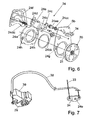
- the second cable 38 is, for example, a Bowden cable whose shell is on the one hand on the second fitting 20, for example on the free-pivoting device 24, and on the other hand on the first fitting 10, for example, on an article 39 of the same, is supported, as in Fig. 7 is shown. In this regard shows Fig.
- the driver 18 of the second fitting 20 remains untwisted, so that the second fitting 20 remains locked.
- the backrest 5 can be freely pivoted forward.
- the free-pivoting device 24 is pivoted back so that the driver 18 can turn back and thus the first fitting 10 locked again.
Landscapes
- Engineering & Computer Science (AREA)
- Aviation & Aerospace Engineering (AREA)
- Transportation (AREA)
- Mechanical Engineering (AREA)
- Seats For Vehicles (AREA)
- Chairs For Special Purposes, Such As Reclining Chairs (AREA)
Claims (10)
- Système de ferrures pour un siège de véhicule comprenant une première ferrure (10), laquelle comprend, pour le déverrouillage, un élément d'entraînement (18) pouvant tourner autour d'un axe (A), une deuxième ferrure (20), un élément de transmission (25) entre les deux ferrures (10, 20), un dispositif de pivotement libre (24) associé à la deuxième ferrure (20), un premier élément de commande (31) lors de l'actionnement duquel les deux ferrures (10, 20) se déverrouillent en ayant recours à l'élément de transmission (25) et un deuxième élément de commande (32) lors de l'actionnement duquel la première ferrure (10) et le dispositif de pivotement libre (24) se déverrouillent, l'élément d'entraînement (18) de la première ferrure (10) recevant - de manière accouplée par entraînement - l'élément de transmission (25), une course à vide étant prévue dans un sens de rotation entre l'élément d'entraînement (18) et l'élément de transmission (25), caractérisé en ce que la course à vide est plus grande que la course de déverrouillage de l'élément d'entraînement (18) nécessaire pour le déverrouillage de la première ferrure (10).
- Système de ferrures selon la revendication 1, caractérisé en ce qu'un profil cannelé est prévu entre l'élément de transmission (25) et l'élément d'entraînement (18), les nervures longitudinales (25a) de l'élément de transmission (25) et les bords du logement de moyeu (18a) de l'élément d'entraînement (18) étant espacés les uns des autres dans un sens de rotation dans la position de départ.
- Système de ferrures selon l'une quelconque des revendications précédentes, caractérisé en ce que l'élément de transmission (25) et/ou l'élément d'entraînement (18) présente(nt) un profil à symétrie ternaire.
- Système de ferrures selon l'une quelconque des revendications précédentes, caractérisé en ce qu'il est prévu un élément de levier (27), lequel peut tourner par rapport à l'élément de transmission (25) et est relié de manière solidaire en rotation à l'élément d'entraînement (18), en particulier enclipsé sur celui-ci.
- Système de ferrures selon la revendication 4, caractérisé en ce que l'élément de levier (27) présente une dimension radiale plus grande que l'élément de transmission (25) et entoure en particulier l'élément de transmission (25).
- Système de ferrures selon la revendication 4 ou 5, caractérisé en ce que le deuxième élément de commande (32) agit sur l'élément de levier (27) au moyen d'un levier de déverrouillage (29).
- Système de ferrures selon la revendication 6, caractérisé en ce que le levier de déverrouillage (29) est relié de manière solidaire en rotation à l'élément de levier (27), en particulier d'un seul tenant ou au moyen d'un profil cannelé supplémentaire.
- Système de ferrures selon l'une quelconque des revendications précédentes, caractérisé en ce que le deuxième élément de commande (32) est en liaison fonctionnelle avec le dispositif de pivotement libre (24) au moyen d'un câble de commande (33).
- Système de ferrures selon l'une quelconque des revendications précédentes, caractérisé en ce que, lors de l'actionnement du premier élément de commande (31), l'élément de transmission (25) tourne et entraîne en rotation l'élément d'entraînement (18) de la première ferrure (10) tandis que, lors de l'actionnement du deuxième élément de commande (32), l'élément de transmission (25) ne tourne pas et l'élément d'entraînement (18) de la première ferrure (10) est entraîné en rotation.
- Siège de véhicule, en particulier siège de véhicule automobile, comprenant une partie d'assise (3) et un dossier (4), caractérisé en ce qu'au moyen d'un système de ferrures selon l'une quelconque des revendications précédentes, l'inclinaison du dossier (4) par rapport à la partie d'assise (3) peut être ajustée et le dossier peut être pivoté librement.
Priority Applications (1)
| Application Number | Priority Date | Filing Date | Title |
|---|---|---|---|
| PL09753654T PL2280845T3 (pl) | 2008-05-28 | 2009-05-26 | System okuć do siedzenia samochodowego |
Applications Claiming Priority (2)
| Application Number | Priority Date | Filing Date | Title |
|---|---|---|---|
| DE102008026176A DE102008026176B4 (de) | 2008-05-28 | 2008-05-28 | Beschlagsystem für einen Fahrzeugsitz |
| PCT/EP2009/003701 WO2009143999A1 (fr) | 2008-05-28 | 2009-05-26 | Système de ferrures pour un siège automobile |
Publications (2)
| Publication Number | Publication Date |
|---|---|
| EP2280845A1 EP2280845A1 (fr) | 2011-02-09 |
| EP2280845B1 true EP2280845B1 (fr) | 2014-04-16 |
Family
ID=40848286
Family Applications (1)
| Application Number | Title | Priority Date | Filing Date |
|---|---|---|---|
| EP09753654.4A Active EP2280845B1 (fr) | 2008-05-28 | 2009-05-26 | Système de ferrures pour un siège automobile |
Country Status (9)
| Country | Link |
|---|---|
| US (1) | US8360527B2 (fr) |
| EP (1) | EP2280845B1 (fr) |
| KR (1) | KR101344383B1 (fr) |
| CN (1) | CN102036850B (fr) |
| BR (1) | BRPI0905377B1 (fr) |
| DE (1) | DE102008026176B4 (fr) |
| PL (1) | PL2280845T3 (fr) |
| RU (1) | RU2509003C2 (fr) |
| WO (1) | WO2009143999A1 (fr) |
Families Citing this family (35)
| Publication number | Priority date | Publication date | Assignee | Title |
|---|---|---|---|---|
| US8523281B2 (en) * | 2009-03-05 | 2013-09-03 | Lear Corporation | Reclining mechanism for vehicle seats |
| DE102009035229A1 (de) * | 2009-07-29 | 2011-02-17 | GM Global Technology Operations, Inc., Detroit | Verstellvorrichtung für die Rückenlehne eines Fahrzeugsitzes, Fahr-zeugsitz mit einer solchen Verstellvorrichtung und Sitzanordnung mit einem solchen Fahrzeugsitz |
| DE102009056397B4 (de) | 2009-11-26 | 2019-03-14 | Adient Luxembourg Holding S.À R.L. | Beschlagsystem für einen Fahrzeugsitz und Fahrzeugsitz |
| DE102010011323B4 (de) | 2010-03-11 | 2011-11-10 | Keiper Gmbh & Co. Kg | Beschlag für einen Fahrzeugsitz |
| DE102010018786B4 (de) | 2010-04-26 | 2022-01-27 | Adient Luxembourg Holding S.À R.L. | Beschlag für einen Fahrzeugsitz und Fahrzeugsitz mit einem solchen Beschlag |
| JP5640558B2 (ja) * | 2010-08-24 | 2014-12-17 | トヨタ紡織株式会社 | リクライニング装置 |
| DE202010015093U1 (de) | 2010-10-29 | 2011-01-05 | Keiper Gmbh & Co. Kg | Beschlagsystem für einen Fahrzeugsitz |
| DE102010052273A1 (de) * | 2010-11-23 | 2012-05-24 | Keiper Gmbh & Co. Kg | Entriegelungseinheit für einen Fahrzeugsitz |
| DE102011004671A1 (de) * | 2011-02-24 | 2012-08-30 | Lear Corporation | Haupt-/Neben-Easy-Entry-Lehnenverstellvorrichtung |
| KR101613687B1 (ko) * | 2011-08-10 | 2016-04-19 | 존슨 컨트롤스 테크놀러지 컴퍼니 | 자동차용 시트 백 프레임 및 그 제조방법 |
| DE102011113747A1 (de) | 2011-09-14 | 2013-03-14 | Keiper Gmbh & Co. Kg | Beschlagsystem für einen Fahrzeugsitz |
| US9102246B2 (en) * | 2013-01-07 | 2015-08-11 | Leggett & Platt Canada Co. | Cable synchronizer system |
| DE102013226002B4 (de) | 2013-02-25 | 2022-04-21 | Keiper Seating Mechanisms Co., Ltd. | Rastbeschlag für einen Fahrzeugsitz sowie Fahrzeugsitz |
| US9889775B2 (en) | 2013-02-14 | 2018-02-13 | Johnson Controls Components Gmbh & Co. Kg | Detent fitting for a vehicle seat, and vehicle seat |
| EP2958769B1 (fr) | 2013-02-25 | 2019-10-02 | Adient Luxembourg Holding S.à r.l. | Ferrure pour un siège de véhicule, procédé de montage d'une ferrure pour un siège de véhicule ainsi que siège de véhicule |
| FR3002885B1 (fr) * | 2013-03-08 | 2016-05-27 | Peugeot Citroen Automobiles Sa | Siege de vehicule avec dossier reglable |
| CN104044487B (zh) * | 2013-03-15 | 2016-08-24 | 李尔公司 | 具有分离式连接器杆的座椅斜靠器 |
| JP2014227026A (ja) * | 2013-05-22 | 2014-12-08 | ナミテイ株式会社 | 駆動シャフト及びこの駆動シャフトを有する電動シート |
| DE102013220359A1 (de) * | 2013-10-09 | 2015-04-09 | Brose Fahrzeugteile Gmbh & Co. Kg, Coburg | Fahrzeugsitz mit mindestens einem Beschlag und einer Betätigungswelle |
| DE102013225698B4 (de) * | 2013-10-16 | 2015-12-03 | Johnson Controls Components Gmbh & Co. Kg | Easy-Entry-System und Fahrzeugsitz mit einem integrierten Easy-Entry-System |
| US10150388B2 (en) | 2014-10-15 | 2018-12-11 | Adient Luxembourg Holding S.à.r.l. | Actuating device, in particular for a vehicle seat, and vehicle seat |
| DE102015203174B4 (de) | 2014-10-15 | 2016-11-03 | Johnson Controls Components Gmbh & Co. Kg | Betätigungsvorrichtung zur Betätigung eines Beschlagsystems, insbesondere für einen Fahrzeugsitz, sowie Fahrzeugsitz |
| US9889774B2 (en) | 2015-08-07 | 2018-02-13 | Fisher & Company, Incorporated | Release mechanism for seat recliner assembly |
| US9802512B1 (en) * | 2016-04-12 | 2017-10-31 | Ford Global Technologies, Llc | Torsion spring bushing |
| US10864830B2 (en) | 2018-04-25 | 2020-12-15 | Fisher & Company, Incorporated | Recliner mechanism having welded encapsulating ring |
| US11124093B2 (en) | 2018-08-08 | 2021-09-21 | Fisher & Company, Incorporated | Recliner mechanism for seat assembly and method of manufacturing |
| US11260777B2 (en) | 2018-08-29 | 2022-03-01 | Fisher & Company, Incorporated | Recliner heart for seat recliner assembly |
| US11364577B2 (en) | 2019-02-11 | 2022-06-21 | Fisher & Company, Incorporated | Recliner mechanism for seat assembly and method of manufacturing |
| US11845367B2 (en) | 2019-04-18 | 2023-12-19 | Fisher & Company, Incorporated | Recliner heart having lubricant member |
| US11052797B2 (en) | 2019-08-09 | 2021-07-06 | Fisher & Company, Incorporated | Recliner heart for seat assembly |
| US11192473B2 (en) | 2019-08-30 | 2021-12-07 | Fisher & Company, Incorporated | Release handle for recliner mechanism of vehicle seat |
| US11607976B2 (en) | 2020-03-06 | 2023-03-21 | Fisher & Company, Incorporated | Recliner mechanism having bracket |
| US11766957B2 (en) | 2021-02-16 | 2023-09-26 | Fisher & Company, Incorporated | Release mechanism for seat recliner assembly |
| US11897372B2 (en) | 2021-05-06 | 2024-02-13 | Fisher & Company, Incorporated | Recliner heart having biasing members |
| US11850975B2 (en) | 2021-06-11 | 2023-12-26 | Fisher & Company, Incorporated | Vehicle seat recliner mechanism with welded spring |
Family Cites Families (21)
| Publication number | Priority date | Publication date | Assignee | Title |
|---|---|---|---|---|
| DE2135600C2 (de) * | 1971-07-16 | 1973-12-13 | Fa. Fritz Keiper, 5630 Remscheidhasten | Gelenkbeschlag für einen Sitz mit einer verstellbaren Ruckenlehne, insbesondere fur einen Kraftfahrzeugsitz |
| CN2181428Y (zh) * | 1993-12-25 | 1994-11-02 | 莫友康 | 多功能的汽车座椅调节装置 |
| FR2725167B1 (fr) | 1994-10-03 | 1996-12-13 | Faure Bertrand Equipements Sa | Perfectionnements aux articulations des dossiers de sieges de vehicules |
| DE19715764C2 (de) | 1997-04-16 | 2000-01-27 | Keiper Gmbh & Co | Neigungseinstellbeschlag mit Freischwenkeinrichtung für eine Rückenlehne eines Kraftfahrzeugsitzes |
| FR2766137B1 (fr) * | 1997-07-15 | 1999-10-01 | Faure Bertrand Equipements Sa | Siege de vehicule equipe d'un mecanisme d'articulation |
| FR2766138B1 (fr) * | 1997-07-17 | 1999-10-01 | Faure Bertrand Equipements Sa | Mecanisme d'articulation pour siege de vehicule, et siege de vehicule equipe d'un tel mecanisme |
| FR2777234B1 (fr) * | 1998-04-09 | 2000-06-16 | Faure Bertrand Equipements Sa | Siege de vehicule equipe d'un mecanisme d'articulation, et mecanisme de memorisation pour un tel siege |
| DE19956235B4 (de) * | 1999-11-23 | 2008-11-06 | Keiper Gmbh & Co.Kg | Rastbeschlag für einen Fahrzeugsitz |
| FR2822419B1 (fr) * | 2000-12-29 | 2003-07-04 | Faurecia Sieges Automobile | Siege de vehicule equipe d'un mecanisme d'articulation |
| FR2850913B1 (fr) * | 2003-02-12 | 2005-04-22 | Faurecia Sieges Automobile | Siege de vehicule automobile comportant un dossier basculable vers l'avant |
| JP4164045B2 (ja) * | 2004-04-30 | 2008-10-08 | シロキ工業株式会社 | シートリクライニング装置 |
| WO2006019979A2 (fr) * | 2004-07-15 | 2006-02-23 | Fisher Dynamics Corporation | Siege inclinable arrondi a mecanisme de goupille coulissante |
| CA2506040C (fr) * | 2005-05-02 | 2014-02-18 | Intier Automotive Inc. | Siege de vehicule et dispositif inclinable a plateau connexe |
| CN100462252C (zh) * | 2005-07-22 | 2009-02-18 | C.劳勃汉默斯坦两合有限公司 | 具有座位部分、座椅靠背和底架的车辆座椅 |
| JP4894192B2 (ja) * | 2005-08-05 | 2012-03-14 | アイシン精機株式会社 | 車両用シート |
| DE202005012733U1 (de) | 2005-08-12 | 2006-12-28 | Brose Fahrzeugteile Gmbh & Co. Kommanditgesellschaft, Coburg | Lehnenklappung |
| DE102006044489B4 (de) * | 2006-01-24 | 2014-07-10 | Keiper Gmbh & Co. Kg | Beschlag für einen Fahrzeugsitz sowie Fahrzeugsitz mit einem solchen Beschlag |
| BRPI0621237A2 (pt) * | 2006-01-24 | 2011-12-06 | Keiper Gmbh & Co Kg | encaixe para assentos de veìculos |
| DE102006044490B4 (de) | 2006-01-24 | 2008-08-28 | Keiper Gmbh & Co.Kg | Beschlag für einen Fahrzeugsitz |
| DE102006041917B3 (de) * | 2006-09-07 | 2008-01-17 | Keiper Gmbh & Co.Kg | Übertragungsvorrichtung für einen Fahrzeugsitz |
| JP5169146B2 (ja) * | 2007-10-30 | 2013-03-27 | アイシン精機株式会社 | 車両用シート装置 |
-
2008
- 2008-05-28 DE DE102008026176A patent/DE102008026176B4/de not_active Expired - Fee Related
-
2009
- 2009-05-26 WO PCT/EP2009/003701 patent/WO2009143999A1/fr active Application Filing
- 2009-05-26 BR BRPI0905377A patent/BRPI0905377B1/pt active IP Right Grant
- 2009-05-26 EP EP09753654.4A patent/EP2280845B1/fr active Active
- 2009-05-26 US US12/672,915 patent/US8360527B2/en active Active
- 2009-05-26 PL PL09753654T patent/PL2280845T3/pl unknown
- 2009-05-26 RU RU2010118664/11A patent/RU2509003C2/ru not_active IP Right Cessation
- 2009-05-26 CN CN2009801190335A patent/CN102036850B/zh active Active
- 2009-05-26 KR KR1020107005348A patent/KR101344383B1/ko active IP Right Grant
Also Published As
| Publication number | Publication date |
|---|---|
| BRPI0905377A2 (pt) | 2015-06-30 |
| DE102008026176B4 (de) | 2010-05-06 |
| RU2010118664A (ru) | 2011-11-20 |
| WO2009143999A1 (fr) | 2009-12-03 |
| PL2280845T3 (pl) | 2014-09-30 |
| BRPI0905377B1 (pt) | 2018-12-18 |
| DE102008026176A1 (de) | 2009-12-03 |
| KR101344383B1 (ko) | 2013-12-24 |
| CN102036850A (zh) | 2011-04-27 |
| RU2509003C2 (ru) | 2014-03-10 |
| US8360527B2 (en) | 2013-01-29 |
| KR20110028425A (ko) | 2011-03-18 |
| EP2280845A1 (fr) | 2011-02-09 |
| US20110215626A1 (en) | 2011-09-08 |
| CN102036850B (zh) | 2013-11-20 |
Similar Documents
| Publication | Publication Date | Title |
|---|---|---|
| EP2280845B1 (fr) | Système de ferrures pour un siège automobile | |
| DE102009056397B4 (de) | Beschlagsystem für einen Fahrzeugsitz und Fahrzeugsitz | |
| DE102005054490B4 (de) | Beschlag für einen Fahrzeugsitz | |
| EP2288512B1 (fr) | Armature pour siège de véhicule | |
| DE102006044490B4 (de) | Beschlag für einen Fahrzeugsitz | |
| DE102007002366B3 (de) | Beschlagsystem für einen Fahrzeugsitz | |
| EP2726324B1 (fr) | Système de ferruere pour un siège de véhicule | |
| EP2240342B1 (fr) | Ferrure pour siège de véhicule | |
| WO2007115601A1 (fr) | Ferrure pour un siege de vehicule | |
| DE102006044489B4 (de) | Beschlag für einen Fahrzeugsitz sowie Fahrzeugsitz mit einem solchen Beschlag | |
| EP1451035B1 (fr) | Repose-bras | |
| EP2958769B1 (fr) | Ferrure pour un siège de véhicule, procédé de montage d'une ferrure pour un siège de véhicule ainsi que siège de véhicule | |
| EP2956333B1 (fr) | Ferrure à cran d'arrêt pour un siège de véhicule et siège de véhicule | |
| EP2525995B1 (fr) | Système de ferrures pour un siège automobile | |
| EP2704921A1 (fr) | Système d'armature pour un siège de véhicule | |
| EP3694744B1 (fr) | Siege de vehicule avec mechanisme easy-entry | |
| EP1539532B1 (fr) | Dispositif de reglage pour siege de vehicule | |
| WO2012022427A2 (fr) | Système de ferrure muni d'un module de déverrouillage du réglage longitudinal | |
| EP2221210B1 (fr) | Armature pour un siège de véhicule | |
| DE102005040629B4 (de) | Beschlag für einen Fahrzeugsitz | |
| DE102009056154B4 (de) | Beschlag für einen Fahrzeugsitz | |
| DE102007030545B3 (de) | Beschlag für einen Fahrzeugsitz | |
| DE102013226002B4 (de) | Rastbeschlag für einen Fahrzeugsitz sowie Fahrzeugsitz | |
| DE19956235A1 (de) | Rastbeschlag für einen Fahrzeugsitz | |
| DE102021134202A1 (de) | Beschlagsystem für einen Fahrzeugsitz, sowie Fahrzeugsitz |
Legal Events
| Date | Code | Title | Description |
|---|---|---|---|
| PUAI | Public reference made under article 153(3) epc to a published international application that has entered the european phase |
Free format text: ORIGINAL CODE: 0009012 |
|
| 17P | Request for examination filed |
Effective date: 20091209 |
|
| AK | Designated contracting states |
Kind code of ref document: A1 Designated state(s): AT BE BG CH CY CZ DE DK EE ES FI FR GB GR HR HU IE IS IT LI LT LU LV MC MK MT NL NO PL PT RO SE SI SK TR |
|
| AX | Request for extension of the european patent |
Extension state: AL BA RS |
|
| DAX | Request for extension of the european patent (deleted) | ||
| GRAP | Despatch of communication of intention to grant a patent |
Free format text: ORIGINAL CODE: EPIDOSNIGR1 |
|
| INTG | Intention to grant announced |
Effective date: 20131217 |
|
| GRAS | Grant fee paid |
Free format text: ORIGINAL CODE: EPIDOSNIGR3 |
|
| GRAA | (expected) grant |
Free format text: ORIGINAL CODE: 0009210 |
|
| AK | Designated contracting states |
Kind code of ref document: B1 Designated state(s): AT BE BG CH CY CZ DE DK EE ES FI FR GB GR HR HU IE IS IT LI LT LU LV MC MK MT NL NO PL PT RO SE SI SK TR |
|
| REG | Reference to a national code |
Ref country code: GB Ref legal event code: FG4D Free format text: NOT ENGLISH |
|
| REG | Reference to a national code |
Ref country code: CH Ref legal event code: EP |
|
| REG | Reference to a national code |
Ref country code: AT Ref legal event code: REF Ref document number: 662297 Country of ref document: AT Kind code of ref document: T Effective date: 20140515 |
|
| REG | Reference to a national code |
Ref country code: IE Ref legal event code: FG4D Free format text: LANGUAGE OF EP DOCUMENT: GERMAN |
|
| REG | Reference to a national code |
Ref country code: DE Ref legal event code: R096 Ref document number: 502009009196 Country of ref document: DE Effective date: 20140522 |
|
| REG | Reference to a national code |
Ref country code: DE Ref legal event code: R081 Ref document number: 502009009196 Country of ref document: DE Owner name: ADIENT LUXEMBOURG HOLDING S.A R.L., LU Free format text: FORMER OWNER: KEIPER GMBH & CO. KG, 67657 KAISERSLAUTERN, DE Effective date: 20140710 Ref country code: DE Ref legal event code: R081 Ref document number: 502009009196 Country of ref document: DE Owner name: ADIENT LUXEMBOURG HOLDING S.A.R.L., LU Free format text: FORMER OWNER: KEIPER GMBH & CO. KG, 67657 KAISERSLAUTERN, DE Effective date: 20140710 Ref country code: DE Ref legal event code: R081 Ref document number: 502009009196 Country of ref document: DE Owner name: JOHNSON CONTROLS COMPONENTS GMBH & CO. KG, DE Free format text: FORMER OWNER: KEIPER GMBH & CO. KG, 67657 KAISERSLAUTERN, DE Effective date: 20140710 |
|
| REG | Reference to a national code |
Ref country code: SK Ref legal event code: T3 Ref document number: E 16602 Country of ref document: SK |
|
| RAP2 | Party data changed (patent owner data changed or rights of a patent transferred) |
Owner name: JOHNSON CONTROLS COMPONENTS GMBH & CO. KG |
|
| REG | Reference to a national code |
Ref country code: NL Ref legal event code: VDEP Effective date: 20140416 |
|
| REG | Reference to a national code |
Ref country code: LT Ref legal event code: MG4D |
|
| REG | Reference to a national code |
Ref country code: PL Ref legal event code: T3 |
|
| PG25 | Lapsed in a contracting state [announced via postgrant information from national office to epo] |
Ref country code: GR Free format text: LAPSE BECAUSE OF FAILURE TO SUBMIT A TRANSLATION OF THE DESCRIPTION OR TO PAY THE FEE WITHIN THE PRESCRIBED TIME-LIMIT Effective date: 20140717 Ref country code: LT Free format text: LAPSE BECAUSE OF FAILURE TO SUBMIT A TRANSLATION OF THE DESCRIPTION OR TO PAY THE FEE WITHIN THE PRESCRIBED TIME-LIMIT Effective date: 20140416 Ref country code: IS Free format text: LAPSE BECAUSE OF FAILURE TO SUBMIT A TRANSLATION OF THE DESCRIPTION OR TO PAY THE FEE WITHIN THE PRESCRIBED TIME-LIMIT Effective date: 20140816 Ref country code: NL Free format text: LAPSE BECAUSE OF FAILURE TO SUBMIT A TRANSLATION OF THE DESCRIPTION OR TO PAY THE FEE WITHIN THE PRESCRIBED TIME-LIMIT Effective date: 20140416 Ref country code: FI Free format text: LAPSE BECAUSE OF FAILURE TO SUBMIT A TRANSLATION OF THE DESCRIPTION OR TO PAY THE FEE WITHIN THE PRESCRIBED TIME-LIMIT Effective date: 20140416 Ref country code: BG Free format text: LAPSE BECAUSE OF FAILURE TO SUBMIT A TRANSLATION OF THE DESCRIPTION OR TO PAY THE FEE WITHIN THE PRESCRIBED TIME-LIMIT Effective date: 20140716 Ref country code: CY Free format text: LAPSE BECAUSE OF FAILURE TO SUBMIT A TRANSLATION OF THE DESCRIPTION OR TO PAY THE FEE WITHIN THE PRESCRIBED TIME-LIMIT Effective date: 20140416 Ref country code: NO Free format text: LAPSE BECAUSE OF FAILURE TO SUBMIT A TRANSLATION OF THE DESCRIPTION OR TO PAY THE FEE WITHIN THE PRESCRIBED TIME-LIMIT Effective date: 20140716 |
|
| PG25 | Lapsed in a contracting state [announced via postgrant information from national office to epo] |
Ref country code: SE Free format text: LAPSE BECAUSE OF FAILURE TO SUBMIT A TRANSLATION OF THE DESCRIPTION OR TO PAY THE FEE WITHIN THE PRESCRIBED TIME-LIMIT Effective date: 20140416 Ref country code: ES Free format text: LAPSE BECAUSE OF FAILURE TO SUBMIT A TRANSLATION OF THE DESCRIPTION OR TO PAY THE FEE WITHIN THE PRESCRIBED TIME-LIMIT Effective date: 20140416 Ref country code: LV Free format text: LAPSE BECAUSE OF FAILURE TO SUBMIT A TRANSLATION OF THE DESCRIPTION OR TO PAY THE FEE WITHIN THE PRESCRIBED TIME-LIMIT Effective date: 20140416 Ref country code: HR Free format text: LAPSE BECAUSE OF FAILURE TO SUBMIT A TRANSLATION OF THE DESCRIPTION OR TO PAY THE FEE WITHIN THE PRESCRIBED TIME-LIMIT Effective date: 20140416 |
|
| PG25 | Lapsed in a contracting state [announced via postgrant information from national office to epo] |
Ref country code: PT Free format text: LAPSE BECAUSE OF FAILURE TO SUBMIT A TRANSLATION OF THE DESCRIPTION OR TO PAY THE FEE WITHIN THE PRESCRIBED TIME-LIMIT Effective date: 20140818 |
|
| REG | Reference to a national code |
Ref country code: CH Ref legal event code: PL |
|
| REG | Reference to a national code |
Ref country code: DE Ref legal event code: R097 Ref document number: 502009009196 Country of ref document: DE |
|
| PG25 | Lapsed in a contracting state [announced via postgrant information from national office to epo] |
Ref country code: LI Free format text: LAPSE BECAUSE OF NON-PAYMENT OF DUE FEES Effective date: 20140531 Ref country code: RO Free format text: LAPSE BECAUSE OF FAILURE TO SUBMIT A TRANSLATION OF THE DESCRIPTION OR TO PAY THE FEE WITHIN THE PRESCRIBED TIME-LIMIT Effective date: 20140416 Ref country code: CH Free format text: LAPSE BECAUSE OF NON-PAYMENT OF DUE FEES Effective date: 20140531 Ref country code: EE Free format text: LAPSE BECAUSE OF FAILURE TO SUBMIT A TRANSLATION OF THE DESCRIPTION OR TO PAY THE FEE WITHIN THE PRESCRIBED TIME-LIMIT Effective date: 20140416 Ref country code: MC Free format text: LAPSE BECAUSE OF FAILURE TO SUBMIT A TRANSLATION OF THE DESCRIPTION OR TO PAY THE FEE WITHIN THE PRESCRIBED TIME-LIMIT Effective date: 20140416 Ref country code: DK Free format text: LAPSE BECAUSE OF FAILURE TO SUBMIT A TRANSLATION OF THE DESCRIPTION OR TO PAY THE FEE WITHIN THE PRESCRIBED TIME-LIMIT Effective date: 20140416 |
|
| PLBE | No opposition filed within time limit |
Free format text: ORIGINAL CODE: 0009261 |
|
| STAA | Information on the status of an ep patent application or granted ep patent |
Free format text: STATUS: NO OPPOSITION FILED WITHIN TIME LIMIT |
|
| REG | Reference to a national code |
Ref country code: IE Ref legal event code: MM4A |
|
| 26N | No opposition filed |
Effective date: 20150119 |
|
| GBPC | Gb: european patent ceased through non-payment of renewal fee |
Effective date: 20140716 |
|
| PG25 | Lapsed in a contracting state [announced via postgrant information from national office to epo] |
Ref country code: IT Free format text: LAPSE BECAUSE OF FAILURE TO SUBMIT A TRANSLATION OF THE DESCRIPTION OR TO PAY THE FEE WITHIN THE PRESCRIBED TIME-LIMIT Effective date: 20140416 |
|
| PG25 | Lapsed in a contracting state [announced via postgrant information from national office to epo] |
Ref country code: IE Free format text: LAPSE BECAUSE OF NON-PAYMENT OF DUE FEES Effective date: 20140526 |
|
| REG | Reference to a national code |
Ref country code: DE Ref legal event code: R097 Ref document number: 502009009196 Country of ref document: DE Effective date: 20150119 |
|
| REG | Reference to a national code |
Ref country code: FR Ref legal event code: PLFP Year of fee payment: 7 |
|
| PG25 | Lapsed in a contracting state [announced via postgrant information from national office to epo] |
Ref country code: GB Free format text: LAPSE BECAUSE OF NON-PAYMENT OF DUE FEES Effective date: 20140716 |
|
| REG | Reference to a national code |
Ref country code: AT Ref legal event code: MM01 Ref document number: 662297 Country of ref document: AT Kind code of ref document: T Effective date: 20140526 |
|
| PG25 | Lapsed in a contracting state [announced via postgrant information from national office to epo] |
Ref country code: SI Free format text: LAPSE BECAUSE OF FAILURE TO SUBMIT A TRANSLATION OF THE DESCRIPTION OR TO PAY THE FEE WITHIN THE PRESCRIBED TIME-LIMIT Effective date: 20140416 |
|
| PG25 | Lapsed in a contracting state [announced via postgrant information from national office to epo] |
Ref country code: AT Free format text: LAPSE BECAUSE OF NON-PAYMENT OF DUE FEES Effective date: 20140526 |
|
| PG25 | Lapsed in a contracting state [announced via postgrant information from national office to epo] |
Ref country code: MT Free format text: LAPSE BECAUSE OF FAILURE TO SUBMIT A TRANSLATION OF THE DESCRIPTION OR TO PAY THE FEE WITHIN THE PRESCRIBED TIME-LIMIT Effective date: 20140416 |
|
| REG | Reference to a national code |
Ref country code: FR Ref legal event code: PLFP Year of fee payment: 8 |
|
| PG25 | Lapsed in a contracting state [announced via postgrant information from national office to epo] |
Ref country code: BE Free format text: LAPSE BECAUSE OF FAILURE TO SUBMIT A TRANSLATION OF THE DESCRIPTION OR TO PAY THE FEE WITHIN THE PRESCRIBED TIME-LIMIT Effective date: 20140531 Ref country code: LU Free format text: LAPSE BECAUSE OF NON-PAYMENT OF DUE FEES Effective date: 20140526 Ref country code: TR Free format text: LAPSE BECAUSE OF FAILURE TO SUBMIT A TRANSLATION OF THE DESCRIPTION OR TO PAY THE FEE WITHIN THE PRESCRIBED TIME-LIMIT Effective date: 20140416 Ref country code: HU Free format text: LAPSE BECAUSE OF FAILURE TO SUBMIT A TRANSLATION OF THE DESCRIPTION OR TO PAY THE FEE WITHIN THE PRESCRIBED TIME-LIMIT; INVALID AB INITIO Effective date: 20090526 |
|
| REG | Reference to a national code |
Ref country code: DE Ref legal event code: R081 Ref document number: 502009009196 Country of ref document: DE Owner name: KEIPER SEATING MECHANISMS CO., LTD., CN Free format text: FORMER OWNER: JOHNSON CONTROLS COMPONENTS GMBH & CO. KG, 67657 KAISERSLAUTERN, DE Ref country code: DE Ref legal event code: R081 Ref document number: 502009009196 Country of ref document: DE Owner name: ADIENT LUXEMBOURG HOLDING S.A R.L., LU Free format text: FORMER OWNER: JOHNSON CONTROLS COMPONENTS GMBH & CO. KG, 67657 KAISERSLAUTERN, DE Ref country code: DE Ref legal event code: R081 Ref document number: 502009009196 Country of ref document: DE Owner name: ADIENT LUXEMBOURG HOLDING S.A.R.L., LU Free format text: FORMER OWNER: JOHNSON CONTROLS COMPONENTS GMBH & CO. KG, 67657 KAISERSLAUTERN, DE |
|
| REG | Reference to a national code |
Ref country code: FR Ref legal event code: PLFP Year of fee payment: 9 |
|
| REG | Reference to a national code |
Ref country code: DE Ref legal event code: R081 Ref document number: 502009009196 Country of ref document: DE Owner name: KEIPER SEATING MECHANISMS CO., LTD., CN Free format text: FORMER OWNER: ADIENT LUXEMBOURG HOLDING S.A.R.L., LUXEMBOURG, LU Ref country code: DE Ref legal event code: R081 Ref document number: 502009009196 Country of ref document: DE Owner name: ADIENT LUXEMBOURG HOLDING S.A R.L., LU Free format text: FORMER OWNER: ADIENT LUXEMBOURG HOLDING S.A.R.L., LUXEMBOURG, LU |
|
| REG | Reference to a national code |
Ref country code: FR Ref legal event code: PLFP Year of fee payment: 10 |
|
| PG25 | Lapsed in a contracting state [announced via postgrant information from national office to epo] |
Ref country code: MK Free format text: LAPSE BECAUSE OF FAILURE TO SUBMIT A TRANSLATION OF THE DESCRIPTION OR TO PAY THE FEE WITHIN THE PRESCRIBED TIME-LIMIT Effective date: 20140416 |
|
| REG | Reference to a national code |
Ref country code: DE Ref legal event code: R082 Ref document number: 502009009196 Country of ref document: DE Representative=s name: KUTZENBERGER WOLFF & PARTNER PATENTANWALTSPART, DE Ref country code: DE Ref legal event code: R081 Ref document number: 502009009196 Country of ref document: DE Owner name: KEIPER SEATING MECHANISMS CO., LTD., CN Free format text: FORMER OWNER: ADIENT YANFENG SEATING MECHANISMS CO., LTD., SHANGHAI, CN Ref country code: DE Ref legal event code: R081 Ref document number: 502009009196 Country of ref document: DE Owner name: KEIPER SEATING MECHANISMS CO., LTD., CN Free format text: FORMER OWNER: ADIENT LUXEMBOURG HOLDING S.A R.L., LUXEMBOURG, LU Ref country code: DE Ref legal event code: R082 Ref document number: 502009009196 Country of ref document: DE Representative=s name: LIEDTKE & PARTNER PATENTANWAELTE, DE |
|
| REG | Reference to a national code |
Ref country code: SK Ref legal event code: TC4A Ref document number: E 16602 Country of ref document: SK Owner name: KEIPER SEATING MECHANISMS CO., LTD., PUDONG, S, CN Effective date: 20220211 Ref country code: SK Ref legal event code: PC4A Ref document number: E 16602 Country of ref document: SK Owner name: ADIENT YANFENG SEATING MECHANISMS CO., LTD, PU, CN Free format text: FORMER OWNER: ADIENT LUXEMBOURG HOLDING S.A R.L., LUXEMBOURG, LU Effective date: 20220211 Ref country code: SK Ref legal event code: PC4A Ref document number: E 16602 Country of ref document: SK Owner name: ADIENT LUXEMBOURG HOLDING S.A R.L., LUXEMBOURG, LU Free format text: FORMER OWNER: JOHNSON CONTROLS METALS HOLDING LTD. & CO. KG, RATINGEN, DE Effective date: 20220210 Ref country code: SK Ref legal event code: PC4A Ref document number: E 16602 Country of ref document: SK Owner name: JOHNSON CONTROLS METALS HOLDING LTD. & CO. KG,, DE Free format text: FORMER OWNER: JOHNSON CONTROLS COMPONENTS GMBH & CO. KG, BURSCHEID, DE Effective date: 20220210 |
|
| REG | Reference to a national code |
Ref country code: DE Ref legal event code: R082 Ref document number: 502009009196 Country of ref document: DE Representative=s name: KUTZENBERGER WOLFF & PARTNER PATENTANWALTSPART, DE |
|
| REG | Reference to a national code |
Ref country code: FR Ref legal event code: PLFP Year of fee payment: 15 |
|
| PGFP | Annual fee paid to national office [announced via postgrant information from national office to epo] |
Ref country code: PL Payment date: 20230314 Year of fee payment: 15 |
|
| PGFP | Annual fee paid to national office [announced via postgrant information from national office to epo] |
Ref country code: FR Payment date: 20230411 Year of fee payment: 15 Ref country code: DE Payment date: 20230331 Year of fee payment: 15 Ref country code: CZ Payment date: 20230515 Year of fee payment: 15 |
|
| PGFP | Annual fee paid to national office [announced via postgrant information from national office to epo] |
Ref country code: SK Payment date: 20230412 Year of fee payment: 15 |