EP2280845B1 - Fitting system for a vehicle seat - Google Patents
Fitting system for a vehicle seat Download PDFInfo
- Publication number
- EP2280845B1 EP2280845B1 EP09753654.4A EP09753654A EP2280845B1 EP 2280845 B1 EP2280845 B1 EP 2280845B1 EP 09753654 A EP09753654 A EP 09753654A EP 2280845 B1 EP2280845 B1 EP 2280845B1
- Authority
- EP
- European Patent Office
- Prior art keywords
- fitting
- driver
- transmission element
- lever
- fitting system
- Prior art date
- Legal status (The legal status is an assumption and is not a legal conclusion. Google has not performed a legal analysis and makes no representation as to the accuracy of the status listed.)
- Active
Links
Images


Classifications
-
- B—PERFORMING OPERATIONS; TRANSPORTING
- B60—VEHICLES IN GENERAL
- B60N—SEATS SPECIALLY ADAPTED FOR VEHICLES; VEHICLE PASSENGER ACCOMMODATION NOT OTHERWISE PROVIDED FOR
- B60N2/00—Seats specially adapted for vehicles; Arrangement or mounting of seats in vehicles
- B60N2/02—Seats specially adapted for vehicles; Arrangement or mounting of seats in vehicles the seat or part thereof being movable, e.g. adjustable
- B60N2/22—Seats specially adapted for vehicles; Arrangement or mounting of seats in vehicles the seat or part thereof being movable, e.g. adjustable the back-rest being adjustable
- B60N2/235—Seats specially adapted for vehicles; Arrangement or mounting of seats in vehicles the seat or part thereof being movable, e.g. adjustable the back-rest being adjustable by gear-pawl type mechanisms
- B60N2/2356—Seats specially adapted for vehicles; Arrangement or mounting of seats in vehicles the seat or part thereof being movable, e.g. adjustable the back-rest being adjustable by gear-pawl type mechanisms with internal pawls
- B60N2/2358—Seats specially adapted for vehicles; Arrangement or mounting of seats in vehicles the seat or part thereof being movable, e.g. adjustable the back-rest being adjustable by gear-pawl type mechanisms with internal pawls and provided with memory locks
-
- B—PERFORMING OPERATIONS; TRANSPORTING
- B60—VEHICLES IN GENERAL
- B60N—SEATS SPECIALLY ADAPTED FOR VEHICLES; VEHICLE PASSENGER ACCOMMODATION NOT OTHERWISE PROVIDED FOR
- B60N2/00—Seats specially adapted for vehicles; Arrangement or mounting of seats in vehicles
- B60N2/02—Seats specially adapted for vehicles; Arrangement or mounting of seats in vehicles the seat or part thereof being movable, e.g. adjustable
- B60N2/20—Seats specially adapted for vehicles; Arrangement or mounting of seats in vehicles the seat or part thereof being movable, e.g. adjustable the back-rest being tiltable, e.g. to permit easy access
-
- B—PERFORMING OPERATIONS; TRANSPORTING
- B60—VEHICLES IN GENERAL
- B60N—SEATS SPECIALLY ADAPTED FOR VEHICLES; VEHICLE PASSENGER ACCOMMODATION NOT OTHERWISE PROVIDED FOR
- B60N2205/00—General mechanical or structural details
- B60N2205/50—Interlocking shaft arrangements transmitting movement between hinge mechanisms on both sides of a seat
Definitions
- the invention relates to a fitting system for a vehicle seat having the features of the preamble of claim 1.
- a fitting system of this kind is, from the DE 198 31 581 A1 known, the second fitting also serves as a free-pivoting device.
- a fitting system with a first fitting, a second fitting and a transmission element between the two fittings is known.
- Each fitting has a shaft piece whose rotation unlocks the fitting.
- the shaft piece is rotated by means of a first operating element on the second fitting and a rotatably mounted thereon first lever is pivoted.
- the first lever takes with a second lever, which is rotatably connected to the transmission element.
- the pivoting second lever rotates the transmission element, which transmits the rotational movement to the shaft piece of the first fitting.
- For free pivoting of the back of the second fitting is associated with an additional free-pivoting device which is locked by means of a pivoting pawl.
- the pawl By means of a second control element, the pawl is opened, wherein the swiveling pawl pivots the second lever by means of a cable.
- the pivoting second lever rotates the transmission element, which transmits the rotational movement to the shaft piece of the first fitting.
- the first fitting unlocks while the second fitting remains locked.
- the invention is based on the object to improve a fitting system of the type mentioned, in particular easier and cheaper to design. This object is achieved by a fitting system with the features of claim 1.
- Advantageous embodiments are the subject of the dependent claims.
- the transmission element - coupled to driving - receives By the driver of the first fitting the transmission element - coupled to driving - receives, wherein between the driver and the transmission element in a rotational direction an idle path is provided, a simple decoupling is available. Overall, less space is required, and the structure of the fitting system is simplified. The free travel is greater than the time required to unlock the first fitting Entriegelungsweg the driver, so that the decoupling is complete. When swiveling free, the second fitting remains locked and stores the previously set inclination (memory function).
- the fitting system according to the invention is intended for a vehicle seat, the backrest tilt adjustable and memorized free to be pivotable, but at the same time should have reduced production costs, which is achieved by using only a single free-pivoting device in the fitting system.
- the free travel ie the decoupling, realized by a spline between the transmission element and the driver, wherein in the initial position, the longitudinal ribs of the transmission element and the edges of the hub receptacle of the driver are spaced apart in a rotational direction.
- the transmission element and / or the driver have a profile with threefold symmetry. Such a profile is for example in the DE 10 2006 041 917 B3 described.
- the free travel according to the invention is significantly larger than a conventional game, which is provided for the purpose of tolerance compensation.
- the actuation of the driver in decoupling from the transmission element is preferably carried out by means of a lever member which rotatable relative to the transmission element and rotatably connected to the driver, in particular clipped, is.
- the lever element arranged outside the first fitting has a larger radial dimension than the transmission element, in particular it encloses the transmission element.
- the second operating element preferably acts by means of an unlocking lever on the lever element, in particular by means of a cable, which is provided on the one hand on the release lever and on the other hand is in operative connection with the second control element.
- the second operating element is also in operative connection with the free-pivoting device by means of a further cable pull, wherein the two said cable pulls can be in series or parallel to one another.
- a further cable pull for the non-rotatable connection of the lever member to the driver and / or the release lever another spline shaft profile may be provided.
- the fitting system according to the invention is preferably designed so that upon actuation of the first control element, the transmission element rotates and immediately rotates the driver of the first fitting (as well as those of the second fitting rotates), whereby with the unlocked fittings a tilt adjustment is possible while pressing the second Operating element, the transmission element remains untwisted and the second control element rotates the driver of the first fitting, which with the unlocked first fitting and the unlocked free-pivoting device, a free pivoting of the backrest is possible.
- a vehicle seat 1 which is presently provided as the front seat of a motor vehicle, has a seat part 3 and a backrest 4.
- the back 4 is adjustable on the one hand in its inclination relative to the seat part 3, whereby more use positions are defined, and on the other hand freely swingable, i. pivoted forward in a non-use position, for example, to facilitate access to a rear row of seats.
- the fitting system 5 has on each vehicle seat side a fitting, which are constructed and coupled in the manner described below.
- a first fitting 10 which is designed as a latching fitting, has a first fitting part 11 and a second fitting part 12, which is rotatable about an axis A relative to the first fitting part 11.
- Axis A defines a subsequently used Cylinder Corridor System.
- the fitting parts 11 and 12 are both disc-shaped and are held together in the axial direction by a Umklamm ceremoniessring 13 which is fixedly connected to the first fitting part 11 and the second fitting part 12 with the interposition of a damper ring 13 a radially overlaps.
- the first fitting 10 therefore forms a disk-shaped unit in terms of construction.
- the first fitting part 11 has a plurality, in this case four, axially projecting guide and bearing segments 11 a, on the one hand on its radially outwardly facing, cylindrically curved surface store the second fitting part 12 and on the other hand in pairs between at least one bar 14, in this case a total of two Latch 14, movable in the radial direction.
- the second fitting part 12 has - as an internally toothed peripheral boundary surface of a cup-like depression - a ring gear 12a, by means of which the second fitting part 12 on the one hand on the guide and bearing segments 11a and on the other hand cooperates with the externally toothed bars 14 to the first fitting 10 to lock.
- an eccentric 16 biased by springs 15 is provided, which is arranged rotatably about the axis A in the middle between the guide and bearing segments 11a.
- a control disk 17 is provided, which is arranged axially between the guide and bearing segments 11 a and the second fitting part 12 , The control plate 17 cooperates with the bars 14, in this case by axially projecting lugs of the bolt 14 engage in scenes of the control disk 17.
- the control disk 17 is non-rotatably mounted on the eccentric 16, which is rotatable by means of a driver 18 - counter to the force of the springs 15 - could also sit directly on the driver 18 in a modified form.
- the driver 18, which is rotatably mounted about the axis A, the control disk 17 by a length of the gate corresponding angle, in this case about 30 °, rotate.
- the preferably made of plastic driver 18 is - in this case from the second fitting part 12 facing away from the first fitting part 11 ago - by central openings of the two fitting parts 11 and 12, which also serve its storage, and - coupled with driving - by the eccentric 16th inserted and is in the axial direction by a retaining ring 19th secured, which is arranged on the side facing away from the first fitting part 11 end face of the second fitting part 12 and which - preferably formed of plastic - is preferably clipped onto the driver 18.
- a fitting lower part 5a fastened to the first fitting part 11 connects the first fitting 10 to the seat part, while a fitting upper part 5b attached to the second fitting part 12 connects the first fitting 10 to the backrest 4.
- a second fitting 20 on the opposite side of the vehicle seat also has the components described above, and the first fitting part 21 is attached to the fitting base 5a, but the fitting upper part 5b is rotatably mounted on the second fitting 20, preferably on the second fitting part 22, and with the second Fitting 22 lockable.
- a locking device and the modification of the fitting upper part 5b and optionally the second fitting part 22 a second fitting 20 associated free-pivoting device 24 is defined.
- the basic structure of such a free-pivoting device 24 is for example from the DE 10 2006 044 490 A 1 known for a geared fitting.
- An annular latching element 24a on the second fitting part 22 serves for the pivotable mounting of the fitting upper part 5b.
- the latching element 24a for example, a collar on which the fitting upper part 5b is pivotally mounted with a bearing opening, which may also be formed in the manner of a collar.
- the latching element 24a is connected directly or indirectly to the second fitting part 22, for example by means of a laser weld (or in another way).
- An annular fixing disk which engages over the fitting upper part 5b in the bearing area, can be fixedly connected to the latching element 24a and optionally to the second fitting part 22 for axial securing of the latter. There is a certain clearance in the radial direction.
- the fitting upper part 5b may consist of two parts fastened to one another, one of which is mounted on the latching element 24a and the other is connected as an adapter to the backrest 4.
- a pawl 24b is pivotally mounted on the upper fitting part 5b on the side facing the latching element 24a by means of a bearing pin, hereinafter referred to as pawl bearing pin 24bb.
- a bearing pin hereinafter referred to as pawl bearing pin 24bb.
- the pawl bearing pin 24bb is formed as an eccentric pin, i. it is rotatably mounted about a pivot axis of the pawl 24b offset axis in the fitting upper part 5b relative to this.
- To compensate for manufacturing tolerances of the pawl bearing pin 24bb is set and fixed so that the pawl 24b with a maximum latch engagement clearance against the locking stop of the locking element 24a, but outside the angular range of the self-locking.
- a clamping element 24c and a catch element 24d are provided as securing elements.
- Par allel to the pawl bearing pin 24bb is an unlocking shaft 24e by means of a bearing bush 24ee rotatably mounted in the fitting upper part 5b.
- the clamping element 24c and rotatably the catch element 24d are pivotable about the common axis defined by the unlocking shaft 24e and aligned with the catch 24b when the fitting upper part 5b is locked.
- the operation of catch element 24d and clamping element 24c is in the DE 44 39 644 A1 described.
- the clamping element 24c rests with an eccentric to the unlocking shaft 24e curved clamping surface at an angle outside the self-locking portion of a contact surface of the pawl 24b.
- the clamping element 24c is biased by a tension spring 24cc designed as a spiral spring, so that it acts on the pawl 24b (and biases it against the latching stop of the latching element 25a).
- the catch element 24d is acted upon by a catch spring 24dd designed as a helical tension spring and lies against a catch spring Stop the fitting upper part 5b.
- the pawl 24b is held in position by the tensioning element 24c, and the catching element 24d is arranged at a small distance from the pawl 24b.
- the clamping element 24c can open because of the lack of self-locking. After a slight pivoting movement of the pawl 24b this comes into abutment against the catch element 24d.
- the catch element 24d then supports the pawl 24b, which rests against the catch element 24d within the self-locking region, preferably tangentially or concentrically and as extensively as possible. This prevents the pawl 24b from opening (further).
- the catching element 24d and the tensioning element 24c are coupled with each other by means of a slot-pin guide with a free travel on entrainment.
- the tensioning element 24c has a slot curved around the unlocking shaft 24e, into which a pin of the catching element 24d engages.
- a lid 24f attached to the fitting upper 5b covers the pawl 24b including the pawl bearing pin 24bb, the catching member 24d, the tensioning member 24c, and the springs 24cc and 24dd, and protects them from contamination.
- the fitting upper part 5b at least one, in this case two diagonally relative to the axis A opposite first stop cam 24g and the locking element 24a in the same number and corresponding arrangement second stop cam 24h.
- Each first stop cam 24g which has a first stop face pointing in the rearward pivoting direction, cooperates with exactly one second stop cam 24h, which has a second stop face pointing in the forward pivoting direction.
- the pairs distributed in the circumferential direction stop cams 24g and 24h are arranged radially spaced from the axis A, formed by an axial, facing each other exhibition in the material in tongue form and facing with its at the free end of the tongues end faces abutment surfaces in the circumferential direction facing each other.
- the stop cams 24g and 24h are only axially present, i. they are arranged radially inside the outer edge of the associated component.
- the stop cams 24g and 24h are issued so that they protrude as much as possible with their stop surfaces in the preferably existing gap between fitting upper part 5b and locking element 24a.
- the exhibitions have the effect of creating a depression in the material on the respective back.
- the abutment surfaces extend in the axial and radial directions, i. without a component in the circumferential direction, so that they can transmit the forces optimally in the case of a system.
- the stop formed by the stop cams 24g and 24h limiting the pivotal movement of the fitting upper part 5b on one side to the rear, both in the normal case after the free swing and in the (rear) crash case.
- the unlocking shaft 24e To unlock the free-pivoting device 24 at the beginning of the free-pivoting the unlocking shaft 24e is rotated about its own axis.
- the unlocking shaft 24e entrains the catching member 24d to open it, i. it disconnects and / or removes it from the latch 24b.
- the catch element 24d takes by means of the slot-pin guide with the clamping element 24c to release the pawl 24b.
- the pivoting catch element 24d comes into abutment against a - substantially radially projecting - Entriegelungsfinger the pawl 24b and pulls on by or supports this when opening. The pawl 24b is thus completely open.
- the two fittings 10 and 20 of the fitting system 5 are coupled by a transmission element 25, which in the present case as a aligned with the axis A. and is formed around this rotatable rod.
- the transmission element 25 is received by the respective driver 18, in the present case by means of a splined shaft profile coupled to driving.
- the transmission element 25 has a profile with threefold symmetry with three longitudinal ribs 25a which are staggered by 120.degree. In the circumferential direction and engage in a respective hub receptacle 18a of the driver 18 designed as a hub in this respect.
- At least in the first fitting 10 is provided between the Studentsträgungselement 25 and the driver 18 in a direction of rotation a free travel ("decoupling"), ie in the starting position, the longitudinal rib 25a and the edge of the hub receptacle 18a over a certain angle - from present about 30 ° - spaced apart.
- the free travel is greater than the unlocking of the first fitting 10 necessary Entriegelungsweg the driver 18.
- no free travel is provided in the starting position.
- driver 18 of the second fitting 20 the free travel is optional.
- At least the driver 18 of the first fitting 10 is formed in its abutting on the end face of the first fitting part 11 flange - at a larger radius relative to the hub - for rotationally fixed receiving a lever element 27.
- the lever element 27 has a hollow cylindrical basic shape, with a larger radial dimension than the transmission element 25, and encloses the transmission element 25 freely rotatable.
- the lever element 27 has on its lateral surface a plurality of, in the present case six, radially projecting longitudinal ribs 27a, while the driver 18 has correspondingly many lever receptacles 18b in said flange region.
- the driver 18 and the preferably made of plastic lever member 27 may be formed so that upon insertion of the longitudinal ribs 27a in the lever receptacles 18b a clip connection is formed.
- the axial dimension of the lever receptacles 18b corresponds to the axial projection of the driver 18 via the end face of the first fitting part 11, while the lever member 27 - and thus also its longitudinal ribs 27a - have a greater axial length, ie via the driver Survive 18.
- an unlocking lever 29 is fixed against rotation on the lifting element 27, for which purpose the unlocking lever 29 has a corresponding internal spline shaft profile in order to receive the longitudinal ribs 27a of the lever element 27.
- the unlocking lever 29 and the lever member 27 are integrally formed.
- a first operating element 31 for example a lever, a handwheel or a loop, sits - axially outside of the two fittings 10 and 20 - rotatably on the transmission element 25 or acts on this - at least indirectly - with a torque. If the first control element 31 is moved, in particular pivoted upwards, the transmission element 25 rotates about the axis A, in FIG Fig. 5 clockwise. In both fittings 10 and 20 of the driver 18 is taken immediately, whereupon each of the eccentric 16 and the control disk 17 is rotated and the bolt 14 are pulled radially inwardly. The second fitting parts 12 and 22 can now be pivoted to another position of use.
- a first operating element 31 for example a lever, a handwheel or a loop
- the first control element 31 is released, whereupon the springs 15 turn back the eccentric 16 and on the one hand press the bolts 14 radially outward so that they engage the ring gear 12a, and on the other hand the driver 18th and turn back the transmission element 25.
- a second operating element 32 which is preferably arranged in the upper region of the backrest 4, is in operative connection with the second fitting 20 associated with the free-pivoting device 24, more precisely with a free-pivoting lever 34, which is non-rotatably mounted on the unlocking shaft 24e by means of a first cable 33.
- the free pivot lever 34 in turn is connected by means of a second cable 38 in operative connection with the release lever 29 of the first fitting 10.
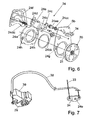
- the second cable 38 is, for example, a Bowden cable whose shell is on the one hand on the second fitting 20, for example on the free-pivoting device 24, and on the other hand on the first fitting 10, for example, on an article 39 of the same, is supported, as in Fig. 7 is shown. In this regard shows Fig.
- the driver 18 of the second fitting 20 remains untwisted, so that the second fitting 20 remains locked.
- the backrest 5 can be freely pivoted forward.
- the free-pivoting device 24 is pivoted back so that the driver 18 can turn back and thus the first fitting 10 locked again.
Description
Die Erfindung betrifft ein Beschlagsystem für einen Fahrzeugsitz mit den Merkmalen des Oberbegriffs des Anspruches 1.The invention relates to a fitting system for a vehicle seat having the features of the preamble of
Ein Beschlagsystem dieser Art ist, aus der
Aus der
Der Erfindung liegt die Aufgabe zu Grunde, ein Beschlagsystern der eingangs genannten Art zu verbessern, insbesondere einfacher und kostengünstiger zu gestalten. Diese Aufgabe wird erfindungsgemäß durch ein Beschlagsystem mit den Merkmalen des Anspruches 1 gelöst. Vorteilhafte Ausgestaltungen sind Gegenstand der Unteransprüche.The invention is based on the object to improve a fitting system of the type mentioned, in particular easier and cheaper to design. This object is achieved by a fitting system with the features of
Indem der Mitnehmer des ersten Beschlags das Übertragungselement - auf Mitnahme gekoppelt - aufnimmt, wobei zwischen dem Mitnehmer und dem Übertragungselement in eine Drehrichtung ein Leerweg vorgesehen ist, steht eine einfache Entkopplung zur Verfügung. Es wird insgesamt weniger Bauraum benötigt, und der Aufbau des Beschlagsystems wird vereinfacht. Der Leerweg ist größer als der zum Entriegeln des ersten Beschlags notwendige Entriegelungsweg des Mitnehmers, so dass die Entkopplung vollständig ist. Beim Freischwenken bleibt der zweite Beschlag verriegelt und speichert so die zuvor eingestellte Neigung (Memory-Funktion). Das erfindungsgemäße Beschlagsystem ist für einen Fahrzeugsitz gedacht, dessen Lehne neigungseinstellbar und memorisiert freischwenkbar sein soll, zugleich aber reduzierte Herstellungskosten haben soll, was durch die Verwendung nur einer einzigen Freischwenkvorrichtung im Beschlagsystem erreicht wird.By the driver of the first fitting the transmission element - coupled to driving - receives, wherein between the driver and the transmission element in a rotational direction an idle path is provided, a simple decoupling is available. Overall, less space is required, and the structure of the fitting system is simplified. The free travel is greater than the time required to unlock the first fitting Entriegelungsweg the driver, so that the decoupling is complete. When swiveling free, the second fitting remains locked and stores the previously set inclination (memory function). The fitting system according to the invention is intended for a vehicle seat, the backrest tilt adjustable and memorized free to be pivotable, but at the same time should have reduced production costs, which is achieved by using only a single free-pivoting device in the fitting system.
In bevorzugter Ausführung wird der Leerweg, d.h. die Entkopplung, durch ein Keilwellenprofil zwischen dem Übertragungselement und dem Mitnehmer verwirklicht, wobei in der Ausgangsstellung die Längsrippen des Übertragungselements und die Ränder der Naben-Aufnahme des Mitnehmers in einer Drehrichtung voneinander beabstandet sind. Bevorzugt ist dabei, dass das Übertragungselement und/oder der Mitnehmer ein Profil mit dreizähliger Symmetrie aufweisen. Ein solches Profil ist beispielsweise in der
Die Betätigung des Mitnehmers bei Entkopplung vom Übertragungselement erfolgt vorzugsweise mittels eines Hebelelements, welches relativ zum Übertragungselement drehbar und mit dem Mitnehmer drehfest verbunden, insbesondere verclipst, ist. Das außerhalb des ersten Beschlags angeordnete Hebelelement weist eine größere radiale Abmessung als das Übertragungselement auf, insbesondere umschließt es das Übertragungselement. Damit wird der radial vorhandene Bauraum außerhalb des ersten Beschlags ausgenutzt. Sofern das Hebelelement keine eigene Befestigungsmöglichkeit für einen Seilzug oder dergleichen bietet, wirkt das zweite Bedienelement vorzugsweise mittels eines Entriegelungshebels auf das Hebelelement ein, insbesondere mittels eines Seilzugs, der einerseits am Entriegelungshebel vorgesehen ist und andererseits mit dem zweiten Bedienelement in Wirkverbindung steht. Vorzugsweise steht das zweite Bedienelement mittels eines weiteren Seilzugs auch in Wirkverbindung mit der Freischwenkvorrichtung, wobei die beiden genannten Seilzüge in Serie oder parallel zueinander liegen können. Für die drehfeste Verbindung des Hebelelements zum Mitnehmer und/oder zum Entriegelungshebel kann ein weiteres Keilwellenprofil vorgesehen sein.The actuation of the driver in decoupling from the transmission element is preferably carried out by means of a lever member which rotatable relative to the transmission element and rotatably connected to the driver, in particular clipped, is. The lever element arranged outside the first fitting has a larger radial dimension than the transmission element, in particular it encloses the transmission element. Thus, the radially existing space outside the first fitting is utilized. If the lever element does not provide its own attachment for a cable or the like, the second operating element preferably acts by means of an unlocking lever on the lever element, in particular by means of a cable, which is provided on the one hand on the release lever and on the other hand is in operative connection with the second control element. Preferably, the second operating element is also in operative connection with the free-pivoting device by means of a further cable pull, wherein the two said cable pulls can be in series or parallel to one another. For the non-rotatable connection of the lever member to the driver and / or the release lever another spline shaft profile may be provided.
Das erfindungsgemäße Beschlagsystem ist vorzugsweise so ausgebildet, dass bei Betätigung des ersten Bedienelementes das Übertragungselement sich dreht und unmittelbar den Mitnehmer des ersten Beschlags dreht (sowie denjenigen des zweiten Beschlags dreht), wodurch mit den entriegelten Beschlägen eine Neigungseinstellung möglich ist, während bei Betätigung des zweiten Bedienelementes das Übertragungselement ungedreht bleibt und das zweite Bedienelement den Mitnehmer des ersten Beschlags dreht, wodurch mit dem entriegelten ersten Beschlag und der entriegelten Freischwenkvorrichtung ein Freischwenken der Lehne möglich ist.The fitting system according to the invention is preferably designed so that upon actuation of the first control element, the transmission element rotates and immediately rotates the driver of the first fitting (as well as those of the second fitting rotates), whereby with the unlocked fittings a tilt adjustment is possible while pressing the second Operating element, the transmission element remains untwisted and the second control element rotates the driver of the first fitting, which with the unlocked first fitting and the unlocked free-pivoting device, a free pivoting of the backrest is possible.
Im folgenden ist die Erfindung anhand eines in der Zeichnung dargestellten Ausführungsbeispiels näher erläutert. Es zeigen
- Fig. 1
- eine perspektivische Ansicht des Ausführungsbeispiels,
- Fig. 2
- einen perspektivische Ansicht des Hebelelements und eines Teils des Übertragungselements,
- Fig. 3
- eine schematische Darstellung eines Fahrzeugsitzes,
- Fig. 4
- eine Explosionsdarstellung des ersten Beschlags,
- Fig. 5
- eine Seitenansicht des ersten Beschlags, wobei die über das erste Beschlagteil axial vorstehenden Teile des Mitnehmers schraffiert sind,
- Fig. 6
- eine Explosionsdarstellung der Freischwenkvorrichtung, und
- Fig. 7
- die mit dem zweiten Bedienelement in Wirkverbindung stehenden Teile.
- Fig. 1
- a perspective view of the embodiment,
- Fig. 2
- a perspective view of the lever member and a part of the transmission element,
- Fig. 3
- a schematic representation of a vehicle seat,
- Fig. 4
- an exploded view of the first fitting,
- Fig. 5
- a side view of the first fitting, wherein over the first fitting part axially projecting parts of the driver are hatched,
- Fig. 6
- an exploded view of the free-pivoting device, and
- Fig. 7
- the parts operatively connected to the second operating element.
Ein Fahrzeugsitz 1, welcher vorliegend als Vordersitz eines Kraftfahrzeuges vorgesehen ist, weist ein Sitzteil 3 und eine Lehne 4 auf. Mittels eines Beschlagsystems 5 ist die Lehne 4 einerseits in ihrer Neigung relativ zum Sitzteil 3 einstellbar, wodurch mehrere Gebrauchsstellungen definiert werden, und andererseits freischwenkbar, d.h. nach vorne in eine Nichtgebrauchsstellung schwenkbar, um beispielsweise den Zugang zu einer hinteren Sitzreihe zu erleichtern. Das Beschlagsystem 5 weist auf jeder Fahrzeugsitzseite einen Beschlag auf, welche in der nachfolgend beschriebenen Weise aufgebaut und gekoppelt sind.A
Ein erster Beschlag 10, welcher als Rastbeschlag ausgebildet ist, weist ein erstes Beschlagteil 11 und ein zweites Beschlagteil 12 auf, welches relativ zum ersten Beschlagteil 11 um eine Achse A verdrehbar ist. Die Achse A definiert ein nachfolgend verwendetes Zylinderkorrdinatensystem. Die Beschlagteile 11 und 12 sind beide scheibenförmig ausgebildet und werden in axialer Richtung durch einen Umklammerungsring 13 zusammengehalten, welcher fest mit dem ersten Beschlagteil 11 verbunden ist und das zweite Beschlagteil 12 unter Zwischenlage eines Dämpferrings 13a radial übergreift. Der erste Beschlag 10 bildet daher in baulicher Hinsicht eine scheibenförmige Einheit.A
Das erste Beschlagteil 11 weist mehrere, vorliegend vier, axial abstehende Führungs- und Lagersegmente 11 a auf, welche einerseits auf ihrer radial nach außen weisenden, zylindrisch gekrümmten Fläche das zweite Beschlagteil 12 lagern und andererseits paarweise zwischen sich wenigstens einen Riegel 14, vorliegend insgesamt zwei Riegel 14, in radialer Richtung beweglich führen. Das zweite Beschlagteil 12 weist - als innenverzahnte Umfangs-Begrenzungsfläche einer napfartigen Vertiefung - einen Zahnkranz 12a auf, mittels welchem das zweite Beschlagteil 12 einerseits auf den Führungs- und Lagersegmenten 11 a gelagert ist und andererseits mit den außenverzahnten Riegeln 14 zusammenwirkt, um den ersten Beschlag 10 zu verriegeln.The first
Um die Riegel 14 zum Verriegeln radial nach außen in den Zahnkranz 12a zu drücken, ist ein durch Federn 15 vorgespannter Exzenter 16 vorgesehen, welcher um die Achse A drehbar in der Mitte zwischen den Führungs- und Lagersegmenten 11 a angeordnet ist. Um die Riegel 14 zum Entriegeln des ersten Beschlags 10 radial nach innen zu ziehen, so dass sie mit dem Zahnkranz 12a außer Eingriff kommen, ist eine Steuerscheibe 17 vorgesehen, welche axial zwischen den Führungs- und Lagersegmenten 11 a und dem zweiten Beschlagteil 12 angeordnet ist. Die Steuerscheibe 17 wirkt mit den Riegeln 14 zusammen, vorliegend indem axial abstehende Nasen der Riegel 14 in Kulissen der Steuerscheibe 17 greifen. Die Steuerscheibe 17 sitzt vorliegend drehfest auf dem Exzenter 16, welcher mittels eines Mitnehmers 18 - entgegen der Kraft der Federn 15 - drehbar ist, könnte in abgewandelter Form auch direkt auf dem Mitnehmer 18 sitzen.In order to press the
Der Mitnehmer 18, welcher um die Achse A drehbar gelagert ist, kann die Steuerscheibe 17 um einen der Länge der Kulisse entsprechenden Winkel, vorliegend um etwa 30°, drehen. Der vorzugsweise aus Kunststoff bestehende Mitnehmer 18 ist - vorliegend von der vom zweiten Beschlagteil 12 abgewandten Stirnseite des ersten Beschlagteils 11 her - durch zentrale Öffnungen der beiden Beschlagteile 11 und 12, welche zugleich seiner Lagerung dienen, und - auf Mitnahme gekoppelt - durch den Exzenter 16 gesteckt und wird in axialer Richtung durch einen Sicherungsring 19 gesichert, welcher auf der vom ersten Beschlagteil 11 abgewandten Stirnseite des zweiten Beschlagteils 12 angeordnet ist und welcher - vorzugsweise aus Kunststoff ausgebildet - vorzugsweise auf den Mitnehmer 18 aufgeclipst ist.The
Ein am ersten Beschlagteil 11 befestigtes Beschlagunterteil 5a verbindet den ersten Beschlag 10 mit dem Sitzteil, während ein am zweiten Beschlagteil 12 befestigtes Beschlagoberteil 5b den ersten Beschlag 10 mit der Lehne 4 verbindet.A fitting
Ein zweiter Beschlag 20 auf der gegenüberliegenden Fahrzeugsitzseite weist auch die oben beschriebenen Bestandteile auf, und dessen erstes Beschlagteil 21 ist am Beschlagunterteil 5a befestigt, jedoch ist das Beschlagoberteil 5b drehbar am zweiten Beschlag 20 gelagert, vorzugsweise an dessen zweitem Beschlagteil 22, und mit dessen zweitem Beschlagteil 22 verriegelbar. Durch die hierfür vorgesehenen Elemente einer Verriegelungsvorrichtung und die Modifikation des Beschlagoberteils 5b und gegebenenfalls des zweiten Beschlagteils 22 wird eine dem zweiten Beschlag 20 zugeordnete Freischwenkvorrichtung 24 definiert. Der grundsätzliche Aufbau einer derartigen Freischwenkvorrichtung 24 ist beispielsweise aus der
Ein ringförmiges Rastelement 24a am zweiten Beschlagteil 22 dient der schwenkbaren Lagerung des Beschlagoberteils 5b. Hierfür weist das Rastelement 24a beispielsweise einen Kragen auf, auf dem das Beschlagoberteil 5b mit einer Lageröffnung, die ebenfalls in der Art eines Kragens ausgebildet sein kann, schwenkbar gelagert ist. Das Rastelement 24a ist direkt oder indirekt mit dem zweiten Beschlagteil 22 fest verbunden, beispielsweise mittels einer Laserschweißnaht (oder auf andere Weise). Eine ringförmige Befestigungscheibe, welche das Beschlagoberteil 5b im Lagerbereich übergreift, kann zur axialen Sicherung des letzteren mit dem Rastelement 24a und optional mit dem zweiten Beschlagteil 22 fest verbunden sein. In radialer Richtung besteht ein gewisses Lagerspiel. Das Beschlagoberteil 5b kann aus zwei aneinander befestigten Teilen bestehen, von denen der eine am Rastelement 24a gelagert und der andere als Adapter mit der Lehne 4 verbunden ist.An
Eine Klinke 24b ist mittels eines Lagerbolzens, im folgenden als Klinkenlagerbolzen 24bb bezeichnet, schwenkbar am Beschlagoberteil 5b auf der dem Rastelement 24a zugewandten Seite gelagert. Zum Verriegeln und zur Begrenzung der Schwenkbewegung des Beschlagoberteils 5b nach vorne im (Front-)Crashfall ist in radialer Verlängerung der Klinke 24b am Rastelement 24a ein - vorliegend nasenförmiger - Rastanschlag vorgesehen, vorzugsweise angeformt. Der Klinkenlagerbolzen 24bb ist als Exzenterbolzen ausgebildet, d.h. er ist um eine zur Schwenkachse der Klinke 24b versetzte Achse im Beschlagoberteil 5b relativ zu diesem drehbar gelagert. Zum Ausgleich der Fertigungstoleranzen ist der Klinkenlagerbolzen 24bb so eingestellt und fixiert, dass die Klinke 24b mit einen maximalem Klinkeneingriff spielfrei an dem Rastanschlag des Rastelements 24a anliegt, allerdings außerhalb des Winkelbereichs der Selbsthemmung.A
Um die Klinke 24b in Rasteingriff mit dem Rastelement 24a zu halten, sind als Sicherungselemente ein Spannelement 24c und ein Fangelement 24d vorgesehen. Par-allel zum Klinkenlagerbolzen 24bb ist eine eine Entriegelungswelle 24e mittels einer Lagerbuchse 24ee drehbar im Beschlagoberteil 5b gelagert. Auf der Entriegelungswelle 24e sitzt schwenkbar das Spannelement 24c und drehfest das Fangelement 24d. Das Fangelement 24d und das Spannelement 24c sind um die durch die Entriegelungswelle 24e definierte gemeinsame Achse schwenkbar und bei verriegeltem Beschlagoberteil 5b auf die Klinke 24b ausgerichtet. Die Funktionsweise von Fangelement 24d und Spannelement 24c ist in der
Das Spannelement 24c liegt mit einer exzentrisch zur Entriegelungswelle 24e gekrümmten Spannfläche in einem Winkel außerhalb des Selbsthemmungsbereichs an einer Anlagefläche der Klinke 24b an. Das Spannelement 24c wird von einer als Spiralfeder ausgebildeten Spannfeder 24cc vorgespannt, so dass es die Klinke 24b beaufschlagt (und diese gegen den Rastanschlag des Rastelements 25a spannt). Dadurch ist das Beschlagoberteil 5b spielfrei mit dem Rastelement 24a und damit mit dem zweiten Beschlagteil 22 verriegelt. Das Fangelement 24d wird von einer als Schrauben-Zugfeder ausgebildeten Fangfeder 24dd beaufschlagt und liegt an einem Anschlag des Beschlagoberteils 5b an. Im Normalfall, d.h. für den normalen Sitzgebrauch, wird die Klinke 24b durch das Spannelement 24c in ihrer Position gehalten, und das Fangelement 24d ist in geringem Abstand zur Klinke 24b angeordnet. Im Crashfall, wenn Crashkräfte auf die Klinke 24b wirken, kann das Spannelement 24c wegen der fehlenden Selbsthemmung öffnen. Nach einer geringfügigen Schwenkbewegung der Klinke 24b gelangt diese in Anlage an das Fangelement 24d. Das Fangelement 24d stützt dann die Klinke 24b ab, welche innerhalb des Selbsthemmungsbereichs am Fangelement 24d anliegt, vorzugsweise tangential oder konzentrisch und möglichst flächig. Damit wird verhindert, dass die Klinke 24b (weiter) öffnet.The clamping
Das Fangelement 24d und das Spannelement 24c sind miteinander mittels einer Schlitz-Zapfen-Führung mit einem Leerweg auf Mitnahme gekoppelt. Hierfür weist das Spannelement 24c einen um die Entriegelungswelle 24e gekrümmten Schlitz auf, in welchen ein Zapfen des Fangelementes 24d greift. Ein am Beschlagoberteil 5b befestigter Deckel 24f deckt die Klinke 24b samt Klinkenlagerbolzen 24bb, das Fangelement 24d, das Spannelement 24c und die Federn 24cc und 24dd ab und schützt diese vor Verschmutzung.The catching
Als Anschlag, der in die Rückwärts-Schwenkrichtung der Lehne 4 (in
Während bekannte Anschläge radial über den äußeren Rand des zugeordneten Bauteils überstehen, stehen die Anschlagnocken 24g und 24h nur axial vor, d.h. sie sind radial innerhalb des äußeren Randes des zugeordneten Bauteils angeordnet. Die Anschlagnocken 24g und 24h sind so ausgestellt, dass sie mit ihren Anschlagflächen möglichst weit in den vorzugsweise vorhandenen Zwischenraum zwischen Beschlagoberteil 5b und Rastelement 24a ragen. Die Ausstellungen bewirken, dass auf der jeweiligen Rückseite eine Vertiefung im Material entsteht. Die Anschlagflächen verlaufen in axialer und radialer Richtung, d.h. ohne Komponente in Umfangsrichtung, so dass sie im Falle einer Anlage die Kräfte optimal übertragen können. Der durch die Anschlagnocken 24g und 24h gebildete Anschlag begrenzt die Schwenkbewegung des Beschlagoberteils 5b einseitig nach hinten, und zwar sowohl im Normalfall nach dem Freischwenken als auch im (Heck-)Crashfall.While known stops protrude radially beyond the outer edge of the associated component, the
Zum Entriegeln der Freischwenkvorrichtung 24 zu Beginn des Freischwenkens wird die Entriegelungswelle 24e um ihre eigene Achse gedreht. Die Entriegelungswelle 24e nimmt das Fangelement 24d mit, um es zu öffnen, d.h. sie trennt und/oder entfernt es von der Klinke 24b. Dabei nimmt das Fangelement 24d mittels der Schlitz-Zapfen-Führung das Spannelement 24c mit, um die Klinke 24b freizugeben. Das schwenkende Fangelement 24d kommt in Anlage an einen - im wesentlichen radial abstehenden - Entriegelungsfinger der Klinke 24b und zieht diese dadurch auf bzw. unterstützt diese beim Öffnen. Die Klinke 24b ist damit vollständig geöffnet.To unlock the free-pivoting
Um den Einstellbereich bei der Neigungseinstellung zu begrenzen, d.h. die relative Verdrehung des zweiten Beschlagteils 22 und des Beschlagunterteils 5a zu begrenzen, steht vom Beschlagunterteil 5a parallel zur Achse A ein Sperranschlag ab, den zwei Begrenzungsanschläge des Rastelementes 24a zwischen sich aufnehmen. Durch Zusammenwirken mit einem entsprechenden Begrenzungsanschlag am Beschlagoberteil 5b kann der Sperranschlag auch das Freischwenken der Lehne 4, d.h. die Schwenkbewegung des Beschlagoberteils 5b nach vorne, begrenzen.In order to limit the adjustment range in the tilt adjustment, i. to limit the relative rotation of the second
Die beiden Beschläge 10 und 20 des Beschlagsystems 5 sind durch ein Übertragungselement 25 gekoppelt, welches vorliegend als eine mit der Achse A fluchtende und um diese drehbare Stange ausgebildet ist. Das Übertragungselement 25 wird vom jeweiligen Mitnehmer 18 aufgenommen, und zwar vorliegend mittels eines Keilwellenprofils auf Mitnahme gekoppelt. Das Übertragungselement 25 weist hierzu ein Profil mit dreizähliger Symmetrie auf mit drei um je 120° in Umfangsrichtung zueinander versetzte Längsrippen 25a, welche in je eine Naben-Aufnahme 18a des diesbezüglich als Nabe ausgebildeten Mitnehmers 18 greift. Wenigstens bei dem ersten Beschlag 10 ist zwischen dem Überträgungselement 25 und dem Mitnehmer 18 in eine Drehrichtung ein Leerweg ("Entkopplungswinkel") vorgesehen, d.h. in der Ausgangsstellung sind die Längsrippe 25a und der Rand der Naben-Aufnahme 18a über einen bestimmten Winkel - von vorliegend etwa 30° - voneinander beabstandet. Der Leerweg ist größer als der zum Entriegeln des ersten Beschlags 10 notwendige Entriegelungsweg des Mitnehmers 18. In die andere Drehrichtung ist in der Ausgangsstellung kein Leerweg vorgesehen. Beim Mitnehmer 18 des zweiten Beschlags 20 ist der Leerweg optional. Dort kann auch eine in beide Drehrichtungen drehfeste Verbindung zwischen Mitnehmer 18 und Übertragungselement 25 vorgesehen sein.The two
Wenigstens der Mitnehmer 18 des ersten Beschlags 10 ist in seinem an der Stirnseite des ersten Beschlagteils 11 anliegenden Flanschbereich - bei einem gegenüber der Nabe größeren Radius - zur drehfesten Aufnahme eines Hebelelementes 27 ausgebildet. Das Hebelelement 27 weist eine hohlzylindrische Grundform auf, mit einer größeren radialen Abmessung als das Übertragungselement 25, und umschließt das Übertragungselement 25 frei drehbar. Zur Bildung eines weiteren Keilwellenprofils weist das Hebelelement 27 auf seiner Mantelfläche mehrere, vorliegend sechs, radial abstehende Längsrippen 27a auf, während der Mitnehmer 18 in besagtem Flanschbereich entsprechend viele Hebel-Aufnahmen 18b aufweist. Dabei können der Mitnehmer 18 und das vorzugsweise aus Kunststoff ausgebildete Hebelelement 27 so ausgebildet sein, dass beim Einführen der Längsrippen 27a in die Hebel-Aufnahmen 18b eine Clipsverbindung entsteht. Die axiale Abmessung der Hebel-Aufnahmen 18b entspricht dem axialen Überstand des Mitnehmers 18 über die Stirnseite des ersten Beschlagteils 11, während das Hebelelement 27 - und damit auch seine Längsrippen 27a - eine größere axiale Länge aufweisen, also über den Mitnehmer 18 überstehen. In diesem überstehenden Bereich sitzt ein Entriegelungshebel 29 drehfest auf dem Hebelement 27, wofür der Entriegelungshebel 29 ein entsprechendes Keilwellen-Innenprofil aufweist, um die Längsrippen 27a des Hebelelements 27 aufzunehmen. In einer alternativen Ausführung sind der Entriegelungshebel 29 und das Hebelelement 27 einstückig ausgebildet.At least the
Entsprechend der beiden Funktionen des Beschlagsystems 5 sind zwei Bedienelemente vorgesehen. Ein erstes Bedienelement 31, beispielsweise ein Hebel, ein Handrad oder eine Schlaufe, sitzt - axial außerhalb der beiden Beschläge 10 und 20 - drehfest auf dem Übertragungselement 25 oder beaufschlagt dieses - wenigstens mittelbar - mit einem Drehmoment. Wird das erste Bedienelement 31 bewegt, insbesondere nach oben geschwenkt, so dreht sich das Übertragungselement 25 um die Achse A, in
Ein zweites Bedienelement 32, welches vorzugsweise im oberen Bereich der Lehne 4 angeordnet ist, steht mittels eines ersten Seilzuges 33 in Wirkverbindung mit der dem zweiten Beschlag 20 zugeordneten Freischwenkvorrichtung 24, genauer gesagt mit einem Freischwenkhebel 34, welcher drehfest auf der Entriegelungswelle 24e sitzt. Der Freischwenkhebel 34 wiederum steht mittels eines zweiten Seilzuges 38 in Wirkverbindung mit dem Entriegelungshebel 29 des ersten Beschlags 10. Der zweite Seilzug 38 ist beispielsweise ein Bowdenzug, dessen Hülle sich einerseits am zweiten Beschlag 20, beispielsweise an der Freischwenkvorrichtung 24, und andererseits am ersten Beschlag 10, beispielsweise an einem Aufsatz 39 desselben, abstützt, wie in
- 11
- Fahrzeugsitzvehicle seat
- 33
- Sitzteilseat part
- 44
- Lehnerest
- 55
- Beschlagsystemhardware system
- 5a5a
- BeschlagunterteilFitting part
- 5b5b
- BeschlagoberteilUpper member
- 1010
- erster Beschlagfirst fitting
- 1111
- erstes Beschlagteilfirst fitting part
- 11a11a
- Führungs- und LagersegmentGuide and bearing segment
- 1212
- zweites Beschlagteilsecond fitting part
- 12a12a
- Zahnkranzsprocket
- 1313
- Umklammerungsringclasping
- 13a13a
- Dämpferingvapor ring
- 1414
- Riegelbars
- 1515
- Federfeather
- 1616
- Exzentereccentric
- 1717
- Steuerscheibecontrol disc
- 1818
- Mitnehmertakeaway
- 18a18a
- Naben-AufnahmeHubs Recording
- 18b18b
- Hebel-AufnahmeLever Recording
- 1919
- Sicherungsringcirclip
- 2020
- zweiter Beschlagsecond fitting
- 2121
- erstes Beschlagteil des zweiten Beschlagsfirst fitting part of the second fitting
- 2222
- zweites Beschlagteil des zweiten Beschlagssecond fitting part of the second fitting
- 2424
- FreischwenkvorrichtungFree-pivoting device
- 24a24a
- Rastelementlocking element
- 24b24b
- Klinkepawl
- 24bb24bb
- KlinkenlagerbolzenPawl bearing bolt
- 24c24c
- Spannelementclamping element
- 24cc24cc
- Spannfedertension spring
- 24d24d
- Fangelementcatching element
- 24dd24dd
- Fangfedercatcher
- 24e24e
- Entriegelungswelleunlocking
- 24ee24ee
- Lagerbuchsebearing bush
- 24f24f
- Deckelcover
- 24g24g
- erster Anschlagnockenfirst stop cam
- 24h24 hours
- zweiter Anschlagnockensecond stop cam
- 2525
- Übertragungselementtransmission element
- 25a25a
- Längsrippe des ÜbertragungselementsLongitudinal rib of the transmission element
- 2727
- Hebelelementlever member
- 27a27a
- Längsrippe des HebelelementsLongitudinal rib of the lever element
- 2929
- Entriegelungshebelrelease lever
- 3131
- erstes Bedienelementfirst operating element
- 3232
- zweites Bedienelementsecond operating element
- 3333
- erster Seilzugfirst cable
- 3434
- FreischwenkhebelFree-pivoting lever
- 3838
- zweiter Seilzugsecond cable
- 3939
- Aufsatzessay
- AA
- Achseaxis
Claims (10)
- Fitting system for a vehicle seat, with a first fitting (10), which has a driver (18) that can be rotated about an axis (A) for the purpose of unlocking, a second fitting (20), a transmission element (25) between the two fittings (10, 20), a free-pivoting device (24) assigned to the second fitting (20), a first operating element (31), upon actuation of which the two fittings (10, 20) unlock, a process involving the use of the transmission element (25), and with a second operating element (32), upon actuation of which the first fitting (10) and the free-pivoting device (24) unlock, the driver (18) of the first fitting (10) accommodating the transmission element (25) in a manner which involves coupling for driving, an idle travel being provided between the driver (18) and the transmission element (25) in one direction of rotation, characterized in that the idle travel is greater than the unlocking travel of the driver (18) required to unlock the first fitting (10).
- Fitting system according to Claim 1, characterized in that a splined-shaft profile is provided between the transmission element (25) and the driver (18), the longitudinal ribs (25a) of the transmission element (25) and the edges of the hub receptacle (18a) of the driver (18) being spaced apart in one direction of rotation in the starting position.
- Fitting system according to one of the preceding claims, characterized in that the transmission element (25) and/or the driver (18) have a profile with three-fold symmetry.
- Fitting system according to one of the preceding claims, characterized in that a lever element (27), which can be rotated relative to the transmission element (25) and is connected, in particular clipped, to the driver (18) in a torsionally rigid manner, is provided.
- Fitting system according to Claim 4, characterized in that the lever element (27) has a larger radial dimension than the transmission element (25) and, in particular, surrounds the transmission element (25).
- Fitting system according to Claim 4 or 5, characterized in that the second operating element (32) acts on the lever element (27) by means of an unlocking lever (29).
- Fitting system according to Claim 6, characterized in that the unlocking lever (29) is connected in a torsionally rigid manner to the lever element (27), in particular integrally or by means of a further splined-shaft profile.
- Fitting system according to one of the preceding claims, characterized in that the second operating element (32) is in operative connection with the free-pivoting device (24) by means of a cable pull (33).
- Fitting system according to one of the preceding claims, characterized in that, when the first operating element (31) is actuated, the transmission element (25) rotates and rotates the driver (18) of the first fitting (10) while, when the second operating element (32) is actuated, the transmission element (25) remains unrotated and the driver (18) of the first fitting (10) is rotated.
- Vehicle seat, in particular motor-vehicle seat, with a seat part (3) and a backrest (4), characterized in that the backrest (4) is adjustable in terms of its inclination relative to the seat part (3) and can be pivoted freely by means of a fitting system according to one of the preceding claims.
Priority Applications (1)
| Application Number | Priority Date | Filing Date | Title |
|---|---|---|---|
| PL09753654T PL2280845T3 (en) | 2008-05-28 | 2009-05-26 | Fitting system for a vehicle seat |
Applications Claiming Priority (2)
| Application Number | Priority Date | Filing Date | Title |
|---|---|---|---|
| DE102008026176A DE102008026176B4 (en) | 2008-05-28 | 2008-05-28 | Fitting system for a vehicle seat |
| PCT/EP2009/003701 WO2009143999A1 (en) | 2008-05-28 | 2009-05-26 | Fitting system for a vehicle seat |
Publications (2)
| Publication Number | Publication Date |
|---|---|
| EP2280845A1 EP2280845A1 (en) | 2011-02-09 |
| EP2280845B1 true EP2280845B1 (en) | 2014-04-16 |
Family
ID=40848286
Family Applications (1)
| Application Number | Title | Priority Date | Filing Date |
|---|---|---|---|
| EP09753654.4A Active EP2280845B1 (en) | 2008-05-28 | 2009-05-26 | Fitting system for a vehicle seat |
Country Status (9)
| Country | Link |
|---|---|
| US (1) | US8360527B2 (en) |
| EP (1) | EP2280845B1 (en) |
| KR (1) | KR101344383B1 (en) |
| CN (1) | CN102036850B (en) |
| BR (1) | BRPI0905377B1 (en) |
| DE (1) | DE102008026176B4 (en) |
| PL (1) | PL2280845T3 (en) |
| RU (1) | RU2509003C2 (en) |
| WO (1) | WO2009143999A1 (en) |
Families Citing this family (35)
| Publication number | Priority date | Publication date | Assignee | Title |
|---|---|---|---|---|
| CN102369118B (en) * | 2009-03-05 | 2016-08-31 | 李尔公司 | Reclining mechanism for vehicle seats |
| DE102009035229A1 (en) * | 2009-07-29 | 2011-02-17 | GM Global Technology Operations, Inc., Detroit | Adjusting device for backrest of vehicle seat, comprises two locking units lying opposite to each other, where locking units are brought in opening position from closing position by force transmission device |
| DE102009056397B4 (en) | 2009-11-26 | 2019-03-14 | Adient Luxembourg Holding S.À R.L. | Fitting system for a vehicle seat and vehicle seat |
| DE102010011323B4 (en) | 2010-03-11 | 2011-11-10 | Keiper Gmbh & Co. Kg | Fitting for a vehicle seat |
| DE102010018786B4 (en) | 2010-04-26 | 2022-01-27 | Adient Luxembourg Holding S.À R.L. | Fitting for a vehicle seat and vehicle seat with such a fitting |
| JP5640558B2 (en) * | 2010-08-24 | 2014-12-17 | トヨタ紡織株式会社 | Reclining device |
| DE202010015093U1 (en) | 2010-10-29 | 2011-01-05 | Keiper Gmbh & Co. Kg | Fitting system for a vehicle seat |
| DE102010052273A1 (en) * | 2010-11-23 | 2012-05-24 | Keiper Gmbh & Co. Kg | Unlocking unit for vehicle seat, particularly motor vehicle seat, has shaft with bearing areas for supporting shaft, where bearing of unlocking unit is fixed in each bearing area on shaft |
| DE102011004671A1 (en) | 2011-02-24 | 2012-08-30 | Lear Corporation | Major / minor-easy-entry Lehnenverstellvorrichtung |
| KR101613687B1 (en) | 2011-08-10 | 2016-04-19 | 존슨 컨트롤스 테크놀러지 컴퍼니 | Seat back frame for vehicle and method for manufacturing same |
| DE102011113747A1 (en) | 2011-09-14 | 2013-03-14 | Keiper Gmbh & Co. Kg | Fitting system for a vehicle seat |
| US9102246B2 (en) * | 2013-01-07 | 2015-08-11 | Leggett & Platt Canada Co. | Cable synchronizer system |
| DE102013226002B4 (en) | 2013-02-25 | 2022-04-21 | Keiper Seating Mechanisms Co., Ltd. | Locking fitting for a vehicle seat and vehicle seat |
| CN105189195B (en) * | 2013-02-14 | 2017-04-19 | 约翰逊控制元件有限两合公司 | Detent fitting for a vehicle seat, and vehicle seat |
| WO2014128297A1 (en) | 2013-02-25 | 2014-08-28 | Johnson Controls Components Gmbh & Co. Kg | Fitting for a vehicle seat, method for assembling a fitting for a vehicle seat, and vehicle seat |
| FR3002885B1 (en) * | 2013-03-08 | 2016-05-27 | Peugeot Citroen Automobiles Sa | VEHICLE SEAT WITH ADJUSTABLE BACKREST |
| CN104044487B (en) * | 2013-03-15 | 2016-08-24 | 李尔公司 | There is the seat reclining device of breakaway connector bar |
| JP2014227026A (en) * | 2013-05-22 | 2014-12-08 | ナミテイ株式会社 | Drive shaft and electrically-driven seat having the same |
| DE102013220359A1 (en) * | 2013-10-09 | 2015-04-09 | Brose Fahrzeugteile Gmbh & Co. Kg, Coburg | Vehicle seat with at least one fitting and one actuating shaft |
| DE102013225698B4 (en) | 2013-10-16 | 2015-12-03 | Johnson Controls Components Gmbh & Co. Kg | Easy entry system and vehicle seat with an integrated easy entry system |
| DE102015203174B4 (en) | 2014-10-15 | 2016-11-03 | Johnson Controls Components Gmbh & Co. Kg | Actuating device for actuating a fitting system, in particular for a vehicle seat, and vehicle seat |
| WO2016058833A1 (en) * | 2014-10-15 | 2016-04-21 | Johnson Controls Components Gmbh & Co. Kg | Actuating device, in particular for a vehicle seat, and vehicle seat |
| US9889774B2 (en) | 2015-08-07 | 2018-02-13 | Fisher & Company, Incorporated | Release mechanism for seat recliner assembly |
| US9802512B1 (en) * | 2016-04-12 | 2017-10-31 | Ford Global Technologies, Llc | Torsion spring bushing |
| US10864830B2 (en) | 2018-04-25 | 2020-12-15 | Fisher & Company, Incorporated | Recliner mechanism having welded encapsulating ring |
| US11124093B2 (en) | 2018-08-08 | 2021-09-21 | Fisher & Company, Incorporated | Recliner mechanism for seat assembly and method of manufacturing |
| US11260777B2 (en) | 2018-08-29 | 2022-03-01 | Fisher & Company, Incorporated | Recliner heart for seat recliner assembly |
| US11364577B2 (en) | 2019-02-11 | 2022-06-21 | Fisher & Company, Incorporated | Recliner mechanism for seat assembly and method of manufacturing |
| US11845367B2 (en) | 2019-04-18 | 2023-12-19 | Fisher & Company, Incorporated | Recliner heart having lubricant member |
| US11052797B2 (en) | 2019-08-09 | 2021-07-06 | Fisher & Company, Incorporated | Recliner heart for seat assembly |
| US11192473B2 (en) | 2019-08-30 | 2021-12-07 | Fisher & Company, Incorporated | Release handle for recliner mechanism of vehicle seat |
| US11607976B2 (en) | 2020-03-06 | 2023-03-21 | Fisher & Company, Incorporated | Recliner mechanism having bracket |
| US11766957B2 (en) | 2021-02-16 | 2023-09-26 | Fisher & Company, Incorporated | Release mechanism for seat recliner assembly |
| US11897372B2 (en) | 2021-05-06 | 2024-02-13 | Fisher & Company, Incorporated | Recliner heart having biasing members |
| US11850975B2 (en) | 2021-06-11 | 2023-12-26 | Fisher & Company, Incorporated | Vehicle seat recliner mechanism with welded spring |
Family Cites Families (21)
| Publication number | Priority date | Publication date | Assignee | Title |
|---|---|---|---|---|
| DE2135600C2 (en) * | 1971-07-16 | 1973-12-13 | Fa. Fritz Keiper, 5630 Remscheidhasten | Articulated fitting for a seat with an adjustable backrest, in particular for a motor vehicle seat |
| CN2181428Y (en) * | 1993-12-25 | 1994-11-02 | 莫友康 | Multifunctional seat adjuster for car |
| FR2725167B1 (en) * | 1994-10-03 | 1996-12-13 | Faure Bertrand Equipements Sa | IMPROVEMENTS ON JOINTS OF VEHICLE SEAT FILES |
| DE19715764C2 (en) | 1997-04-16 | 2000-01-27 | Keiper Gmbh & Co | Tilt adjustment fitting with free pivoting device for a backrest of a motor vehicle seat |
| FR2766137B1 (en) * | 1997-07-15 | 1999-10-01 | Faure Bertrand Equipements Sa | VEHICLE SEAT HAVING A JOINT MECHANISM |
| FR2766138B1 (en) * | 1997-07-17 | 1999-10-01 | Faure Bertrand Equipements Sa | ARTICULATION MECHANISM FOR VEHICLE SEAT, AND VEHICLE SEAT EQUIPPED WITH SUCH A MECHANISM |
| FR2777234B1 (en) * | 1998-04-09 | 2000-06-16 | Faure Bertrand Equipements Sa | VEHICLE SEAT HAVING A JOINT MECHANISM, AND MEMORY MECHANISM FOR SUCH A SEAT |
| DE19956235B4 (en) * | 1999-11-23 | 2008-11-06 | Keiper Gmbh & Co.Kg | Lock fitting for a vehicle seat |
| FR2822419B1 (en) * | 2000-12-29 | 2003-07-04 | Faurecia Sieges Automobile | VEHICLE SEAT HAVING A JOINT MECHANISM |
| FR2850913B1 (en) * | 2003-02-12 | 2005-04-22 | Faurecia Sieges Automobile | MOTOR VEHICLE SEAT COMPRISING A FOLDING FOLDER FORWARD |
| JP4164045B2 (en) * | 2004-04-30 | 2008-10-08 | シロキ工業株式会社 | Seat reclining device |
| US20060012232A1 (en) * | 2004-07-15 | 2006-01-19 | Coughlin Craig G | Round recliner with sliding pin mechanism |
| CA2506040C (en) * | 2005-05-02 | 2014-02-18 | Intier Automotive Inc. | A vehicle seat and a disc recliner therefor |
| CN100462252C (en) * | 2005-07-22 | 2009-02-18 | C.劳勃汉默斯坦两合有限公司 | Vehicle seat with a seat part, a seat back and an underframe |
| JP4894192B2 (en) * | 2005-08-05 | 2012-03-14 | アイシン精機株式会社 | Vehicle seat |
| DE202005012733U1 (en) | 2005-08-12 | 2006-12-28 | Brose Fahrzeugteile Gmbh & Co. Kommanditgesellschaft, Coburg | Lehnenklappung |
| DE102006044490B4 (en) * | 2006-01-24 | 2008-08-28 | Keiper Gmbh & Co.Kg | Fitting for a vehicle seat |
| PL1976723T3 (en) | 2006-01-24 | 2010-11-30 | Keiper Gmbh & Co Kg | Fitting for a vehicle seat |
| DE102006044489B4 (en) | 2006-01-24 | 2014-07-10 | Keiper Gmbh & Co. Kg | Fitting for a vehicle seat and vehicle seat with such a fitting |
| DE102006041917B3 (en) | 2006-09-07 | 2008-01-17 | Keiper Gmbh & Co.Kg | Torque transfer unit, between an adjustment hand wheel and a motor vehicle seat, has a toothed shaft within the structured opening of a hub in a positive fit |
| JP5169146B2 (en) * | 2007-10-30 | 2013-03-27 | アイシン精機株式会社 | Vehicle seat device |
-
2008
- 2008-05-28 DE DE102008026176A patent/DE102008026176B4/en not_active Expired - Fee Related
-
2009
- 2009-05-26 PL PL09753654T patent/PL2280845T3/en unknown
- 2009-05-26 EP EP09753654.4A patent/EP2280845B1/en active Active
- 2009-05-26 US US12/672,915 patent/US8360527B2/en active Active
- 2009-05-26 RU RU2010118664/11A patent/RU2509003C2/en not_active IP Right Cessation
- 2009-05-26 KR KR1020107005348A patent/KR101344383B1/en active IP Right Grant
- 2009-05-26 BR BRPI0905377A patent/BRPI0905377B1/en active IP Right Grant
- 2009-05-26 CN CN2009801190335A patent/CN102036850B/en active Active
- 2009-05-26 WO PCT/EP2009/003701 patent/WO2009143999A1/en active Application Filing
Also Published As
| Publication number | Publication date |
|---|---|
| CN102036850B (en) | 2013-11-20 |
| US8360527B2 (en) | 2013-01-29 |
| RU2509003C2 (en) | 2014-03-10 |
| CN102036850A (en) | 2011-04-27 |
| RU2010118664A (en) | 2011-11-20 |
| PL2280845T3 (en) | 2014-09-30 |
| WO2009143999A1 (en) | 2009-12-03 |
| KR20110028425A (en) | 2011-03-18 |
| EP2280845A1 (en) | 2011-02-09 |
| US20110215626A1 (en) | 2011-09-08 |
| DE102008026176B4 (en) | 2010-05-06 |
| BRPI0905377A2 (en) | 2015-06-30 |
| KR101344383B1 (en) | 2013-12-24 |
| DE102008026176A1 (en) | 2009-12-03 |
| BRPI0905377B1 (en) | 2018-12-18 |
Similar Documents
| Publication | Publication Date | Title |
|---|---|---|
| EP2280845B1 (en) | Fitting system for a vehicle seat | |
| DE102009056397B4 (en) | Fitting system for a vehicle seat and vehicle seat | |
| DE102005054490B4 (en) | Fitting for a vehicle seat | |
| EP2288512B1 (en) | Fitting for a vehicle seat | |
| DE102006044490B4 (en) | Fitting for a vehicle seat | |
| DE102007002366B3 (en) | Fitting system for a vehicle seat | |
| EP2726324B1 (en) | Fitting system for a vehicle seat | |
| EP2240342B1 (en) | Fitting for a vehicle seat | |
| EP2001706A1 (en) | Fitting for a vehicle seat | |
| DE102006044489B4 (en) | Fitting for a vehicle seat and vehicle seat with such a fitting | |
| EP1451035B1 (en) | Armrest | |
| EP2958769B1 (en) | Fitting for a vehicle seat, method for assembling a fitting for a vehicle seat, and vehicle seat | |
| EP2956333B1 (en) | Detent fitting for a vehicle seat, and vehicle seat | |
| EP2525995B1 (en) | Fitting system for a vehicle seat | |
| EP2704921A1 (en) | Fitting system for a vehicle seat | |
| EP3694744B1 (en) | Vehicule seat with easy-entry mechanism | |
| EP1539532B1 (en) | Adjuster for a vehicle seat | |
| EP2221210B1 (en) | Fitting for a vehicle seat | |
| DE102005040629B4 (en) | Fitting for a vehicle seat | |
| DE102009056154B4 (en) | Fitting for a vehicle seat | |
| DE102007030545B3 (en) | Fitting for vehicle seat, particularly for motor vehicle seat, has prestressed clamping element that protects handle in operational position under normal conditions, where prestressed clamping element protects handle in case of crash | |
| DE102013226002B4 (en) | Locking fitting for a vehicle seat and vehicle seat | |
| DE19956235A1 (en) | Locking fitting for motor vehicle seat consists of two parts with bolt guide acting as bearing for both parts | |
| DE102021134202A1 (en) | Fitting system for a vehicle seat and vehicle seat | |
| DE102019211855A1 (en) | Backrest mechanism for a seat assembly and manufacturing method |
Legal Events
| Date | Code | Title | Description |
|---|---|---|---|
| PUAI | Public reference made under article 153(3) epc to a published international application that has entered the european phase |
Free format text: ORIGINAL CODE: 0009012 |
|
| 17P | Request for examination filed |
Effective date: 20091209 |
|
| AK | Designated contracting states |
Kind code of ref document: A1 Designated state(s): AT BE BG CH CY CZ DE DK EE ES FI FR GB GR HR HU IE IS IT LI LT LU LV MC MK MT NL NO PL PT RO SE SI SK TR |
|
| AX | Request for extension of the european patent |
Extension state: AL BA RS |
|
| DAX | Request for extension of the european patent (deleted) | ||
| GRAP | Despatch of communication of intention to grant a patent |
Free format text: ORIGINAL CODE: EPIDOSNIGR1 |
|
| INTG | Intention to grant announced |
Effective date: 20131217 |
|
| GRAS | Grant fee paid |
Free format text: ORIGINAL CODE: EPIDOSNIGR3 |
|
| GRAA | (expected) grant |
Free format text: ORIGINAL CODE: 0009210 |
|
| AK | Designated contracting states |
Kind code of ref document: B1 Designated state(s): AT BE BG CH CY CZ DE DK EE ES FI FR GB GR HR HU IE IS IT LI LT LU LV MC MK MT NL NO PL PT RO SE SI SK TR |
|
| REG | Reference to a national code |
Ref country code: GB Ref legal event code: FG4D Free format text: NOT ENGLISH |
|
| REG | Reference to a national code |
Ref country code: CH Ref legal event code: EP |
|
| REG | Reference to a national code |
Ref country code: AT Ref legal event code: REF Ref document number: 662297 Country of ref document: AT Kind code of ref document: T Effective date: 20140515 |
|
| REG | Reference to a national code |
Ref country code: IE Ref legal event code: FG4D Free format text: LANGUAGE OF EP DOCUMENT: GERMAN |
|
| REG | Reference to a national code |
Ref country code: DE Ref legal event code: R096 Ref document number: 502009009196 Country of ref document: DE Effective date: 20140522 |
|
| REG | Reference to a national code |
Ref country code: DE Ref legal event code: R081 Ref document number: 502009009196 Country of ref document: DE Owner name: ADIENT LUXEMBOURG HOLDING S.A R.L., LU Free format text: FORMER OWNER: KEIPER GMBH & CO. KG, 67657 KAISERSLAUTERN, DE Effective date: 20140710 Ref country code: DE Ref legal event code: R081 Ref document number: 502009009196 Country of ref document: DE Owner name: ADIENT LUXEMBOURG HOLDING S.A.R.L., LU Free format text: FORMER OWNER: KEIPER GMBH & CO. KG, 67657 KAISERSLAUTERN, DE Effective date: 20140710 Ref country code: DE Ref legal event code: R081 Ref document number: 502009009196 Country of ref document: DE Owner name: JOHNSON CONTROLS COMPONENTS GMBH & CO. KG, DE Free format text: FORMER OWNER: KEIPER GMBH & CO. KG, 67657 KAISERSLAUTERN, DE Effective date: 20140710 |
|
| REG | Reference to a national code |
Ref country code: SK Ref legal event code: T3 Ref document number: E 16602 Country of ref document: SK |
|
| RAP2 | Party data changed (patent owner data changed or rights of a patent transferred) |
Owner name: JOHNSON CONTROLS COMPONENTS GMBH & CO. KG |
|
| REG | Reference to a national code |
Ref country code: NL Ref legal event code: VDEP Effective date: 20140416 |
|
| REG | Reference to a national code |
Ref country code: LT Ref legal event code: MG4D |
|
| REG | Reference to a national code |
Ref country code: PL Ref legal event code: T3 |
|
| PG25 | Lapsed in a contracting state [announced via postgrant information from national office to epo] |
Ref country code: GR Free format text: LAPSE BECAUSE OF FAILURE TO SUBMIT A TRANSLATION OF THE DESCRIPTION OR TO PAY THE FEE WITHIN THE PRESCRIBED TIME-LIMIT Effective date: 20140717 Ref country code: LT Free format text: LAPSE BECAUSE OF FAILURE TO SUBMIT A TRANSLATION OF THE DESCRIPTION OR TO PAY THE FEE WITHIN THE PRESCRIBED TIME-LIMIT Effective date: 20140416 Ref country code: IS Free format text: LAPSE BECAUSE OF FAILURE TO SUBMIT A TRANSLATION OF THE DESCRIPTION OR TO PAY THE FEE WITHIN THE PRESCRIBED TIME-LIMIT Effective date: 20140816 Ref country code: NL Free format text: LAPSE BECAUSE OF FAILURE TO SUBMIT A TRANSLATION OF THE DESCRIPTION OR TO PAY THE FEE WITHIN THE PRESCRIBED TIME-LIMIT Effective date: 20140416 Ref country code: FI Free format text: LAPSE BECAUSE OF FAILURE TO SUBMIT A TRANSLATION OF THE DESCRIPTION OR TO PAY THE FEE WITHIN THE PRESCRIBED TIME-LIMIT Effective date: 20140416 Ref country code: BG Free format text: LAPSE BECAUSE OF FAILURE TO SUBMIT A TRANSLATION OF THE DESCRIPTION OR TO PAY THE FEE WITHIN THE PRESCRIBED TIME-LIMIT Effective date: 20140716 Ref country code: CY Free format text: LAPSE BECAUSE OF FAILURE TO SUBMIT A TRANSLATION OF THE DESCRIPTION OR TO PAY THE FEE WITHIN THE PRESCRIBED TIME-LIMIT Effective date: 20140416 Ref country code: NO Free format text: LAPSE BECAUSE OF FAILURE TO SUBMIT A TRANSLATION OF THE DESCRIPTION OR TO PAY THE FEE WITHIN THE PRESCRIBED TIME-LIMIT Effective date: 20140716 |
|
| PG25 | Lapsed in a contracting state [announced via postgrant information from national office to epo] |
Ref country code: SE Free format text: LAPSE BECAUSE OF FAILURE TO SUBMIT A TRANSLATION OF THE DESCRIPTION OR TO PAY THE FEE WITHIN THE PRESCRIBED TIME-LIMIT Effective date: 20140416 Ref country code: ES Free format text: LAPSE BECAUSE OF FAILURE TO SUBMIT A TRANSLATION OF THE DESCRIPTION OR TO PAY THE FEE WITHIN THE PRESCRIBED TIME-LIMIT Effective date: 20140416 Ref country code: LV Free format text: LAPSE BECAUSE OF FAILURE TO SUBMIT A TRANSLATION OF THE DESCRIPTION OR TO PAY THE FEE WITHIN THE PRESCRIBED TIME-LIMIT Effective date: 20140416 Ref country code: HR Free format text: LAPSE BECAUSE OF FAILURE TO SUBMIT A TRANSLATION OF THE DESCRIPTION OR TO PAY THE FEE WITHIN THE PRESCRIBED TIME-LIMIT Effective date: 20140416 |
|
| PG25 | Lapsed in a contracting state [announced via postgrant information from national office to epo] |
Ref country code: PT Free format text: LAPSE BECAUSE OF FAILURE TO SUBMIT A TRANSLATION OF THE DESCRIPTION OR TO PAY THE FEE WITHIN THE PRESCRIBED TIME-LIMIT Effective date: 20140818 |
|
| REG | Reference to a national code |
Ref country code: CH Ref legal event code: PL |
|
| REG | Reference to a national code |
Ref country code: DE Ref legal event code: R097 Ref document number: 502009009196 Country of ref document: DE |
|
| PG25 | Lapsed in a contracting state [announced via postgrant information from national office to epo] |
Ref country code: LI Free format text: LAPSE BECAUSE OF NON-PAYMENT OF DUE FEES Effective date: 20140531 Ref country code: RO Free format text: LAPSE BECAUSE OF FAILURE TO SUBMIT A TRANSLATION OF THE DESCRIPTION OR TO PAY THE FEE WITHIN THE PRESCRIBED TIME-LIMIT Effective date: 20140416 Ref country code: CH Free format text: LAPSE BECAUSE OF NON-PAYMENT OF DUE FEES Effective date: 20140531 Ref country code: EE Free format text: LAPSE BECAUSE OF FAILURE TO SUBMIT A TRANSLATION OF THE DESCRIPTION OR TO PAY THE FEE WITHIN THE PRESCRIBED TIME-LIMIT Effective date: 20140416 Ref country code: MC Free format text: LAPSE BECAUSE OF FAILURE TO SUBMIT A TRANSLATION OF THE DESCRIPTION OR TO PAY THE FEE WITHIN THE PRESCRIBED TIME-LIMIT Effective date: 20140416 Ref country code: DK Free format text: LAPSE BECAUSE OF FAILURE TO SUBMIT A TRANSLATION OF THE DESCRIPTION OR TO PAY THE FEE WITHIN THE PRESCRIBED TIME-LIMIT Effective date: 20140416 |
|
| PLBE | No opposition filed within time limit |
Free format text: ORIGINAL CODE: 0009261 |
|
| STAA | Information on the status of an ep patent application or granted ep patent |
Free format text: STATUS: NO OPPOSITION FILED WITHIN TIME LIMIT |
|
| REG | Reference to a national code |
Ref country code: IE Ref legal event code: MM4A |
|
| 26N | No opposition filed |
Effective date: 20150119 |
|
| GBPC | Gb: european patent ceased through non-payment of renewal fee |
Effective date: 20140716 |
|
| PG25 | Lapsed in a contracting state [announced via postgrant information from national office to epo] |
Ref country code: IT Free format text: LAPSE BECAUSE OF FAILURE TO SUBMIT A TRANSLATION OF THE DESCRIPTION OR TO PAY THE FEE WITHIN THE PRESCRIBED TIME-LIMIT Effective date: 20140416 |
|
| PG25 | Lapsed in a contracting state [announced via postgrant information from national office to epo] |
Ref country code: IE Free format text: LAPSE BECAUSE OF NON-PAYMENT OF DUE FEES Effective date: 20140526 |
|
| REG | Reference to a national code |
Ref country code: DE Ref legal event code: R097 Ref document number: 502009009196 Country of ref document: DE Effective date: 20150119 |
|
| REG | Reference to a national code |
Ref country code: FR Ref legal event code: PLFP Year of fee payment: 7 |
|
| PG25 | Lapsed in a contracting state [announced via postgrant information from national office to epo] |
Ref country code: GB Free format text: LAPSE BECAUSE OF NON-PAYMENT OF DUE FEES Effective date: 20140716 |
|
| REG | Reference to a national code |
Ref country code: AT Ref legal event code: MM01 Ref document number: 662297 Country of ref document: AT Kind code of ref document: T Effective date: 20140526 |
|
| PG25 | Lapsed in a contracting state [announced via postgrant information from national office to epo] |
Ref country code: SI Free format text: LAPSE BECAUSE OF FAILURE TO SUBMIT A TRANSLATION OF THE DESCRIPTION OR TO PAY THE FEE WITHIN THE PRESCRIBED TIME-LIMIT Effective date: 20140416 |
|
| PG25 | Lapsed in a contracting state [announced via postgrant information from national office to epo] |
Ref country code: AT Free format text: LAPSE BECAUSE OF NON-PAYMENT OF DUE FEES Effective date: 20140526 |
|
| PG25 | Lapsed in a contracting state [announced via postgrant information from national office to epo] |
Ref country code: MT Free format text: LAPSE BECAUSE OF FAILURE TO SUBMIT A TRANSLATION OF THE DESCRIPTION OR TO PAY THE FEE WITHIN THE PRESCRIBED TIME-LIMIT Effective date: 20140416 |
|
| REG | Reference to a national code |
Ref country code: FR Ref legal event code: PLFP Year of fee payment: 8 |
|
| PG25 | Lapsed in a contracting state [announced via postgrant information from national office to epo] |
Ref country code: BE Free format text: LAPSE BECAUSE OF FAILURE TO SUBMIT A TRANSLATION OF THE DESCRIPTION OR TO PAY THE FEE WITHIN THE PRESCRIBED TIME-LIMIT Effective date: 20140531 Ref country code: LU Free format text: LAPSE BECAUSE OF NON-PAYMENT OF DUE FEES Effective date: 20140526 Ref country code: TR Free format text: LAPSE BECAUSE OF FAILURE TO SUBMIT A TRANSLATION OF THE DESCRIPTION OR TO PAY THE FEE WITHIN THE PRESCRIBED TIME-LIMIT Effective date: 20140416 Ref country code: HU Free format text: LAPSE BECAUSE OF FAILURE TO SUBMIT A TRANSLATION OF THE DESCRIPTION OR TO PAY THE FEE WITHIN THE PRESCRIBED TIME-LIMIT; INVALID AB INITIO Effective date: 20090526 |
|
| REG | Reference to a national code |
Ref country code: DE Ref legal event code: R081 Ref document number: 502009009196 Country of ref document: DE Owner name: KEIPER SEATING MECHANISMS CO., LTD., CN Free format text: FORMER OWNER: JOHNSON CONTROLS COMPONENTS GMBH & CO. KG, 67657 KAISERSLAUTERN, DE Ref country code: DE Ref legal event code: R081 Ref document number: 502009009196 Country of ref document: DE Owner name: ADIENT LUXEMBOURG HOLDING S.A R.L., LU Free format text: FORMER OWNER: JOHNSON CONTROLS COMPONENTS GMBH & CO. KG, 67657 KAISERSLAUTERN, DE Ref country code: DE Ref legal event code: R081 Ref document number: 502009009196 Country of ref document: DE Owner name: ADIENT LUXEMBOURG HOLDING S.A.R.L., LU Free format text: FORMER OWNER: JOHNSON CONTROLS COMPONENTS GMBH & CO. KG, 67657 KAISERSLAUTERN, DE |
|
| REG | Reference to a national code |
Ref country code: FR Ref legal event code: PLFP Year of fee payment: 9 |
|
| REG | Reference to a national code |
Ref country code: DE Ref legal event code: R081 Ref document number: 502009009196 Country of ref document: DE Owner name: KEIPER SEATING MECHANISMS CO., LTD., CN Free format text: FORMER OWNER: ADIENT LUXEMBOURG HOLDING S.A.R.L., LUXEMBOURG, LU Ref country code: DE Ref legal event code: R081 Ref document number: 502009009196 Country of ref document: DE Owner name: ADIENT LUXEMBOURG HOLDING S.A R.L., LU Free format text: FORMER OWNER: ADIENT LUXEMBOURG HOLDING S.A.R.L., LUXEMBOURG, LU |
|
| REG | Reference to a national code |
Ref country code: FR Ref legal event code: PLFP Year of fee payment: 10 |
|
| PG25 | Lapsed in a contracting state [announced via postgrant information from national office to epo] |
Ref country code: MK Free format text: LAPSE BECAUSE OF FAILURE TO SUBMIT A TRANSLATION OF THE DESCRIPTION OR TO PAY THE FEE WITHIN THE PRESCRIBED TIME-LIMIT Effective date: 20140416 |
|
| REG | Reference to a national code |
Ref country code: DE Ref legal event code: R082 Ref document number: 502009009196 Country of ref document: DE Representative=s name: KUTZENBERGER WOLFF & PARTNER PATENTANWALTSPART, DE Ref country code: DE Ref legal event code: R081 Ref document number: 502009009196 Country of ref document: DE Owner name: KEIPER SEATING MECHANISMS CO., LTD., CN Free format text: FORMER OWNER: ADIENT YANFENG SEATING MECHANISMS CO., LTD., SHANGHAI, CN Ref country code: DE Ref legal event code: R081 Ref document number: 502009009196 Country of ref document: DE Owner name: KEIPER SEATING MECHANISMS CO., LTD., CN Free format text: FORMER OWNER: ADIENT LUXEMBOURG HOLDING S.A R.L., LUXEMBOURG, LU Ref country code: DE Ref legal event code: R082 Ref document number: 502009009196 Country of ref document: DE Representative=s name: LIEDTKE & PARTNER PATENTANWAELTE, DE |
|
| REG | Reference to a national code |
Ref country code: SK Ref legal event code: TC4A Ref document number: E 16602 Country of ref document: SK Owner name: KEIPER SEATING MECHANISMS CO., LTD., PUDONG, S, CN Effective date: 20220211 Ref country code: SK Ref legal event code: PC4A Ref document number: E 16602 Country of ref document: SK Owner name: ADIENT YANFENG SEATING MECHANISMS CO., LTD, PU, CN Free format text: FORMER OWNER: ADIENT LUXEMBOURG HOLDING S.A R.L., LUXEMBOURG, LU Effective date: 20220211 Ref country code: SK Ref legal event code: PC4A Ref document number: E 16602 Country of ref document: SK Owner name: ADIENT LUXEMBOURG HOLDING S.A R.L., LUXEMBOURG, LU Free format text: FORMER OWNER: JOHNSON CONTROLS METALS HOLDING LTD. & CO. KG, RATINGEN, DE Effective date: 20220210 Ref country code: SK Ref legal event code: PC4A Ref document number: E 16602 Country of ref document: SK Owner name: JOHNSON CONTROLS METALS HOLDING LTD. & CO. KG,, DE Free format text: FORMER OWNER: JOHNSON CONTROLS COMPONENTS GMBH & CO. KG, BURSCHEID, DE Effective date: 20220210 |
|
| REG | Reference to a national code |
Ref country code: DE Ref legal event code: R082 Ref document number: 502009009196 Country of ref document: DE Representative=s name: KUTZENBERGER WOLFF & PARTNER PATENTANWALTSPART, DE |
|
| REG | Reference to a national code |
Ref country code: FR Ref legal event code: PLFP Year of fee payment: 15 |
|
| PGFP | Annual fee paid to national office [announced via postgrant information from national office to epo] |
Ref country code: PL Payment date: 20230314 Year of fee payment: 15 |
|
| PGFP | Annual fee paid to national office [announced via postgrant information from national office to epo] |
Ref country code: FR Payment date: 20230411 Year of fee payment: 15 Ref country code: DE Payment date: 20230331 Year of fee payment: 15 Ref country code: CZ Payment date: 20230515 Year of fee payment: 15 |
|
| PGFP | Annual fee paid to national office [announced via postgrant information from national office to epo] |
Ref country code: SK Payment date: 20230412 Year of fee payment: 15 |