EP2273037B1 - Profilé de raccordement, en particulier profilé de raccordement d'intrados - Google Patents
Profilé de raccordement, en particulier profilé de raccordement d'intrados Download PDFInfo
- Publication number
- EP2273037B1 EP2273037B1 EP10164508.3A EP10164508A EP2273037B1 EP 2273037 B1 EP2273037 B1 EP 2273037B1 EP 10164508 A EP10164508 A EP 10164508A EP 2273037 B1 EP2273037 B1 EP 2273037B1
- Authority
- EP
- European Patent Office
- Prior art keywords
- web
- transverse
- lateral
- connection profile
- leg
- Prior art date
- Legal status (The legal status is an assumption and is not a legal conclusion. Google has not performed a legal analysis and makes no representation as to the accuracy of the status listed.)
- Not-in-force
Links
Images


Classifications
-
- E—FIXED CONSTRUCTIONS
- E06—DOORS, WINDOWS, SHUTTERS, OR ROLLER BLINDS IN GENERAL; LADDERS
- E06B—FIXED OR MOVABLE CLOSURES FOR OPENINGS IN BUILDINGS, VEHICLES, FENCES OR LIKE ENCLOSURES IN GENERAL, e.g. DOORS, WINDOWS, BLINDS, GATES
- E06B1/00—Border constructions of openings in walls, floors, or ceilings; Frames to be rigidly mounted in such openings
- E06B1/62—Tightening or covering joints between the border of openings and the frame or between contiguous frames
-
- E—FIXED CONSTRUCTIONS
- E04—BUILDING
- E04F—FINISHING WORK ON BUILDINGS, e.g. STAIRS, FLOORS
- E04F13/00—Coverings or linings, e.g. for walls or ceilings
- E04F13/02—Coverings or linings, e.g. for walls or ceilings of plastic materials hardening after applying, e.g. plaster
- E04F13/04—Bases for plaster
- E04F13/06—Edge-protecting borders
- E04F13/068—Edge-protecting borders combined with mesh material or the like to allow plaster to bond therewith
-
- E—FIXED CONSTRUCTIONS
- E04—BUILDING
- E04F—FINISHING WORK ON BUILDINGS, e.g. STAIRS, FLOORS
- E04F13/00—Coverings or linings, e.g. for walls or ceilings
- E04F13/02—Coverings or linings, e.g. for walls or ceilings of plastic materials hardening after applying, e.g. plaster
- E04F13/04—Bases for plaster
- E04F13/06—Edge-protecting borders
- E04F2013/063—Edge-protecting borders for corners
-
- E—FIXED CONSTRUCTIONS
- E06—DOORS, WINDOWS, SHUTTERS, OR ROLLER BLINDS IN GENERAL; LADDERS
- E06B—FIXED OR MOVABLE CLOSURES FOR OPENINGS IN BUILDINGS, VEHICLES, FENCES OR LIKE ENCLOSURES IN GENERAL, e.g. DOORS, WINDOWS, BLINDS, GATES
- E06B1/00—Border constructions of openings in walls, floors, or ceilings; Frames to be rigidly mounted in such openings
- E06B1/62—Tightening or covering joints between the border of openings and the frame or between contiguous frames
- E06B2001/624—Tightening or covering joints between the border of openings and the frame or between contiguous frames with parts to be embedded in the stucco layer or otherwise linked to this layer
Definitions
- connection profile strip in particular a soffit connection profile strip.
- connection profiles are either plastered, or serve the inclusion of cladding panels or the like.
- connection profile strip is known, in which an existing of a hard plastic material profile body which is formed there with one or more Einputzstegen, on the underside of a soft, elastic plastic material existing and thus deformable portion is formed.
- the section is formed via an inner and outer web on the underside of the hard profile body, these two webs are connected to each other via a transverse web.
- the outside in the mounting position web runs pointed with the crossbar in the region of the edge, wherein the underside of the tapered edge portion is free of adhesive coating and the edge itself preferably beyond the adhesive plane over which the bar is attached to the component is located.
- This results in that the profile strip rests in firm adhesion on the adhesive layer on the frame or rail component, while at the same time the soft edge or the soft edge portion rests firmly, flat and tight on the door or window frame or the rail.
- the sealing edge portion is held with high force in its contact with the frame or the rail.
- the flexibility of the soft-elastic portion allows both a deformation of this portion in the vertical and in the horizontal direction, about which any wall or component movements can be compensated.
- a horizontal movement of the soft-elastic portion is compressed or stretched relative to the profile body, in a horizontal movement, it is moved almost transversely to the profile body laterally to the left or right.
- Object of the present invention is to improve a connection profile strip to the effect that an even greater mobility of the soft-elastic portion, in particular in the transverse or horizontal direction, is given.
- connection profile strip in particular a soffit connection profile strip provided with a profiled body with two side bars and a crosspiece connecting them, as well as one made of a soft plastic material, substantially U-shaped portion consisting of two side legs and a transverse leg connecting them consists, wherein the profile body is inserted into the U-shaped portion and the two side legs are attached to the outside of the side webs, wherein between the transverse web and the transverse leg at least one flexible element is provided, and wherein at least the edge portion in which the transverse leg and the side legs of the U-shaped section lying outside in the assembly position converge pointedly, so that the edge lies in or beyond the plane of an adhesive layer located below the transverse leg.
- the terminal strip according to the invention of quasi U-shaped because two side bars having profile body inserted into the likewise substantially U-shaped soft-elastic portion, ie, that the side legs of the U-shaped soft-elastic portion drawn into the area laterally of the side webs of the profile body and secured to the outside thereof. That is to say that unlike in the prior art, the side legs are not formed on the underside of the profile body, but on the outer sides of the side webs. They can thus be made longer at the same height, resulting in greater flexibility and greater deformability, in particular if the two side legs extend at an angle to the respective side web, so run obliquely to the side web. In other words, the side legs virtually protrude away from the respective side web, resulting in an even larger, in particular horizontal, displacement possibility.
- the soft elastic U-shaped portion In order to give the soft elastic U-shaped portion sufficient stability with high flexibility, according to the invention further provided at least one located between the transverse web and the transverse leg flexible element, which also consists of soft-elastic plastic material as well as the section itself, and which is equally easily deformable. Finally, after the outer side leg of the soft-elastic portion in the mounting position with the transverse leg expires pointed and the edge is in or beyond the adhesive layer, care is taken for a very tight connection.
- the flexible element which is located between transverse leg and transverse web, is preferably designed as a loop, which has an elliptical shape and is formed on the underside of the transverse web as well as on the upper side of the transverse leg.
- the loop shape causes lateral curved connecting portions, which extend from the transverse leg to the crosspiece.
- This embodiment allows a roll-like movement when the transverse leg is displaced horizontally or parallel to the crossbar, which further the increase in horizontal mobility, especially in conjunction with an oblique arrangement of the side legs of the U-shaped soft-elastic portion, is beneficial. It would also be conceivable, for example, instead of a closed loop to provide two separate connecting webs, which are executed bent, and equally allow a roll-like movement.
- the two side legs of the soft-elastic U-shaped section preferably run at an angle to the respective side web, but it is already sufficient according to the invention if only the side leg lying outside in the assembly position runs obliquely.
- the profiled body between the side bars or between a side bar and provided on the profile body central web a projecting from the profile body fabric strip and this is fixed to the profile body, preferably soft elastic plastic material is introduced.
- a fabric strip is used for solid embedding and connection to the applied after mounting the bar plaster layer. It is fixed from the hard plastic material existing profile body, including a plastic mass, which is preferably also made of soft-elastic material, so that it can be easily injected in the ingot production in this open profile body chamber serves.
- the plastic compound can either fill the entire area between the two side webs, wherein the fabric strip would then preferably be provided on the side web which is located in the assembly position.
- the plastic mass-receiving chamber may preferably be undercut via at least one laterally projecting nose, which is integrally formed on a side web or the central web.
- the fabric strip may be e.g. also be glued by means of a suitable adhesive to a web or other strip section. Alternatively, a fixation by sewing the fabric strip is conceivable as the fabric strip can be firmly connected by welding to the bar.
- the adhesive layer which serves to fix the connection profile strip, can either be applied directly to the transverse limb, but it is also conceivable to use a double-sided foam adhesive tape which is glued to the transverse limb with an adhesive layer, the other adhesive layer serves to fix the strips.
- a double-sided foam adhesive tape which is glued to the transverse limb with an adhesive layer, the other adhesive layer serves to fix the strips.
- a thin strip preferably made of hard plastic material, to which the adhesive layer or the foam adhesive tape is applied to the transverse limb.
- the profile body and optionally the stiffening strip is preferably made of rigid PVC, while the flexible portion and optionally the plastic mass of soft PVC, a thermoplastic elastomer (TPE) or other sufficiently soft or flexible plastic.
- TPE thermoplastic elastomer
- the profile body and optionally the strip and the U-shaped section and optionally the plastic compound are preferably molded together in a co-extrusion process. For example, it is conceivable in a first coextrusion step to spray the profile body and the U-shaped section together, after which the fabric strip is positioned and the plastic compound is injected, it being possible for all process operations to be carried out in a single coextrusion process step.
- a Folienanklebesteg is formed on the outside of the side web lying in the mounting position above the attachment point of the side leg. This rupture over a predetermined breaking point web is used to fix a window or the door during the Einputzvorgangs protective film.
- the Folienanklebesteg is preferably formed slightly below the end edge of the side bar, so that the plaster during plastering of the bar along this side bar can be removed clean and the Folienanklebesteg does not bother.
- Fig. 1 shows a component in the form of a window or door frame 1, and a window or door 2 in a conventional manner.
- a connection profile strip 3 according to the invention is glued on which a Folienanklebesteg 4 projects to the soffit inside, on which a film 5 for protection glued to the window or door.
- the profile strip 3 according to the invention further comprises three Einputzstege 6, wherein two are located as side bars outside and one is arranged as a middle web between them.
- the Einputzstege 6 are plastered in a plaster layer 7.
- the basic use of such a soffit connection profile is known in the art and need not be explained in detail.
- Fig. 2 shows a first embodiment of a connection profile strip 8 according to the invention, which in the context of a in Fig. 1 shown assembly can be used. It consists of a profile body 9 made of hard plastic material, such as rigid PVC, comprising two side webs, namely a side web 10 lying in the mounting position and a side web 11 lying in the mounting position, both of which are connected to one another via a transverse web 12. Furthermore, a central web 13 is provided.
- the profiled body 9 is open at the top so that there are virtually two parallel chambers extending into the plane of the drawing. In the in Fig.
- Fig. 2 Chamber shown left between the side bar 11, at the upper end of an inwardly projecting nose 14 is formed, and the central web 13, a fabric strip 15 is arranged, which is plastered into the plaster layer 7. It runs on the inside of the web 13 and is fixed by means of a plastic compound 16, which may be a soft, elastic plastic, for example soft PVC, which is injected as part of a coextrusion process. The chamber is almost completely filled.
- Fig. 2 further shows an integrally formed on the central web 13, transversely projecting Einputznase 17, which of course other anchoring serving Einputz bamboon can be provided, although not shown in detail.
- a Folienanklebesteg 18 is formed on the outside of the side web 10, which can be canceled via a material weakening 19 after completion of the Einputzvorgangs.
- the Folienanklebesteg 18 has an adhesive layer 20, for example, formed by a foam adhesive tape to which the film can be adhered.
- connection profile strip 8 further comprises a U-shaped section 21, consisting of two side legs 22 (the side leg lying in the assembled position) and 23 (the inner side leg) and a transverse limb 24 connecting the same.
- the U-shaped soft-elastic section 21 For example, it is made of soft PVC.
- Fig. 2 shows the profile body 9 is inserted into the U-shaped portion 21 respectively between the side legs 22, 23 was added. These are molded onto the two outer sides 25, 26 of the side webs 10, 11 and fastened there. Visible are the side legs 22, 23 obliquely to the respective side bars 10, 11, ie, they run obliquely to this point up to the respective attachment points.
- a flexible element 33 is provided between the underside of the transverse web 12 and the top of the transverse leg 24, which is part of the section 21 or is integrally connected thereto and designed as a loop 34. It is firmly connected on one side with the slightly inwardly curved transverse web 12 and on the other side in one piece with the transverse leg 24.
- the loop is hollow and elliptical in shape, so that curved connecting webs form on both sides.
- the inventive shape of the elastic portion 21 with its sloping side legs 22, 23 in conjunction with the loop-shaped elastic member 33 allows a very flexible and in both the vertical and in the horizontal direction a large freedom of movement enabling construction, with the relatively large component movements without detachment the bonding or plaster connection can be compensated. Because the relatively long because to just in the middle or over the middle of the respective side surfaces 25, 26 of the side bars 10, 11 tightened mounting position of the side legs 22, 23 and the resulting length and their oblique course allow a considerable horizontal movement, too the bent connecting portions of the loop 34 readily follow roll-off.
- Fig. 3 shows a further embodiment of a connection profile strip 8 according to the invention, wherein in this and the following figures as far as possible the same reference numerals for the same parts are used.
- the structure of the profile body 9 corresponds to the profile body 9 Fig. 2 , the corresponding description is referenced.
- the flexible U-shaped portion 21 has here two flexible elements 33 in the form of two curved connecting webs 35 which are bent outwardly and equally allow a roll-like movement, as the self-contained loop 34 from Fig.
- a bar 36 preferably made of hard plastic material such as rigid PVC, which is very thin, arranged on the underside of the transverse leg 24, to which the double-sided adhesive tape 32 is glued with its adhesive layer 31.
- the edges 29 and 30 of the tapered edge portions 27, 28 in the respective connecting regions between the side legs 22, 23 and the transverse leg 24 are here again beyond the adhesive layer plane, so that a firm, tight contact of the respective edge portion 27, 28 is ensured.
- Fig. 4 shows a further embodiment of the connection profile strip 8 according to the invention, in which case the structure of the profile body 9 of the Fig. 2 and 3 equivalent.
- the elastic U-shaped section 21 here also has the two side legs 22, 23 and the transverse limb 24 and the respective edge sections 27, 28, in which the respective limbs converge, with the edges 29, 30.
- an adhesive layer 31 is applied directly to the underside of the transverse limb 24, ie, the adhesive is applied directly to the transverse limb 24, without the interposition of a foam adhesive tape. It would be equally possible, for example to arrange a hard bar 36 on the transverse leg 24 and apply directly to this adhesive.
- transverse leg 24 and transverse web 12 extend here two flexible elements 33 in the form of straight connecting webs 37, which are as well as the curved connecting webs 35 integral with the transverse leg 24 and consequently also made of soft-elastic material such as soft PVC. These webs are sufficiently flexible to allow a vertical as well as horizontal movement.
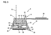
- Fig. 5 a further embodiment of a profile strip 8 according to the invention, in which case the profile body 9 has only the two side webs 10, 11, wherein on both side webs inwardly projecting lugs 14 are provided. It thus forms only a chamber which is completely filled with the plastic compound 16, which serves to fix the fabric strip 15.
- the fabric strip 15 extends here in the region of the inner side web 11.
- the elastic portion 21 is also designed here U-shaped, it has two side legs 22, 23 and the transverse leg 24.
- only the edge portion 27 is made tapered so that its edge 29 beyond the plane of the adhesive layer 31, again provided by a foam adhesive tape 32, is located.
- the edge portion 28 is ultimately not tapered running, in the mounting position, the edge 30 is not on the component. That is, the foam adhesive tape 32 is "sealed" from one side only.
- transverse web 12 and the transverse leg 24 extend here two intersecting connecting webs 38, which form the elastic, flexible elements 33, which allow the component movement.
Landscapes
- Engineering & Computer Science (AREA)
- Architecture (AREA)
- Civil Engineering (AREA)
- Structural Engineering (AREA)
- Building Environments (AREA)
- Orthopedics, Nursing, And Contraception (AREA)
- Floor Finish (AREA)
Claims (11)
- Baguette de profilé d'assemblage, en particulier baguette de profilé d'assemblage d'intrados, avec un corps de profilé (9) avec deux entretoises latérales (10, 11) et une entretoise transversale (12) reliant celles-ci, ainsi qu'une section essentiellement en forme de U (21), constituée d'un matériau en plastique souple et de deux branches latérales (22, 23) et d'une branche transversale (24) reliant celles-ci, dans laquelle le corps de profilé (9) est inséré dans la section en forme de U (21) et les deux branches latérales (22, 23) sont fixées sur les côtés extérieurs (25, 26) des entretoises latérales (10, 11), dans laquelle au moins un élément flexible (33) est prévu entre l'entretoise transversale (12) et la branche transversale (24), et dans laquelle au moins la section de bord (27) dans laquelle se rejoignent la branche transversale (24) et la branche latérale (22) de la section en forme de U (21) située à l'extérieur dans la position de montage se termine en pointe, de telle sorte que le bord (29) se trouve dans le ou au-delà du plan d'une couche adhésive (31) située en dessous de la branche transversale (24).
- Baguette de profilé d'assemblage selon la revendication 1, caractérisée en ce que la section de bord (28) dans laquelle se rejoignent la branche transversale (24) et la branche latérale (11) de la section en forme de U (21) située à l'intérieur dans la position de montage se termine en pointe, de telle sorte que le bord (30) se trouve dans le ou au-delà du plan de la couche adhésive (31) située en dessous de la branche transversale (24).
- Baguette de profilé d'assemblage selon la revendication 1 ou 2, caractérisée en ce que l'élément flexible (33) est conçu comme une boucle (34) attachée à l'entretoise transversale (12) et à la branche transversale (24), ou comme une entretoise de liaison (35, 37, 38) s'étendant de l'entretoise transversale (12) à la branche transversale (24).
- Baguette de profilé d'assemblage selon la revendication 3, caractérisée en ce qu'il est prévu deux ou plus de deux entretoises de liaison (35, 37, 38) se croisant éventuellement et/ou conçues courbes.
- Baguette de profilé d'assemblage selon l'une des revendications précédentes, caractérisée en ce qu'au moins la branche latérale (22) située à l'extérieur dans la position de montage, de préférence les deux branches latérales (22, 23), s'étend/s'étendent sous un angle par rapport à l'entretoise latérale (10, 11) respective.
- Baguette de profilé d'assemblage selon l'une des revendications précédentes, caractérisée en ce qu'une bande de tissu (1) faisant saillie à partir du corps de profilé (9) et une masse de plastique (16) fixant celle-ci sur le corps de profilé (9) sont incorporées sur le corps de profilé (9), entre les entretoises latérales (10, 11) ou entre une entretoise latérale (10, 11) et une entretoise médiane (13) prévue sur le corps de profilé (9).
- Baguette de profilé d'assemblage selon la revendication 6, caractérisée en ce qu'il est prévu un nez (14) faisant saillie latéralement sur au moins une entretoise latérale (10, 11) ou sur l'entretoise médiane (13).
- Baguette de profilé d'assemblage selon l'une des revendications précédentes, caractérisée en ce qu'une bande adhésive (32) comportant la couche adhésive (31) est disposée sur la branche transversale (24) ou sur une baguette (36) renforçant la branche transversale (24), ou en ce que la couche adhésive (31) est appliquée directement sur la branche transversale (24) ou la baguette (36).
- Baguette de profilé d'assemblage selon l'une des revendications précédentes, caractérisée en ce que le corps de profilé (9) et éventuellement la baguette (36) sont constitués de PVC dur, et la section flexible (21) et éventuellement la masse de plastique (16) sont constituées de PVC souple, d'un élastomère thermoplastique (TPE) ou d'un autre plastique suffisamment souple.
- Baguette de profilé d'assemblage selon l'une des revendications précédentes, caractérisée en ce que le corps de profilé (9) et éventuellement la baguette (36) et la section en forme de U (21) et éventuellement la masse de plastique (16) sont moulés les uns sur les autres au cours d'un procédé de coextrusion.
- Baguette de profilé d'assemblage selon l'une des revendications précédentes, caractérisée en ce qu'une entretoise de collage de feuille (18) est moulée sur le côté extérieur (25) de l'entretoise latérale (10) située à l'extérieur dans la position de montage, au-dessus du point de fixation de la branche latérale (22).
Priority Applications (1)
| Application Number | Priority Date | Filing Date | Title |
|---|---|---|---|
| PL10164508T PL2273037T3 (pl) | 2009-06-04 | 2010-05-31 | Łącząca listwa profilowana, zwłaszcza ościeżowa łącząca listwa profilowana |
Applications Claiming Priority (1)
| Application Number | Priority Date | Filing Date | Title |
|---|---|---|---|
| DE102009023958A DE102009023958B3 (de) | 2009-06-04 | 2009-06-04 | Anschlussprofilleiste, insbesondere Laibungsanschlussprofilleiste |
Publications (3)
| Publication Number | Publication Date |
|---|---|
| EP2273037A2 EP2273037A2 (fr) | 2011-01-12 |
| EP2273037A3 EP2273037A3 (fr) | 2014-09-03 |
| EP2273037B1 true EP2273037B1 (fr) | 2015-01-28 |
Family
ID=42710770
Family Applications (1)
| Application Number | Title | Priority Date | Filing Date |
|---|---|---|---|
| EP10164508.3A Not-in-force EP2273037B1 (fr) | 2009-06-04 | 2010-05-31 | Profilé de raccordement, en particulier profilé de raccordement d'intrados |
Country Status (3)
| Country | Link |
|---|---|
| EP (1) | EP2273037B1 (fr) |
| DE (1) | DE102009023958B3 (fr) |
| PL (1) | PL2273037T3 (fr) |
Families Citing this family (5)
| Publication number | Priority date | Publication date | Assignee | Title |
|---|---|---|---|---|
| DE102011004769A1 (de) * | 2011-02-25 | 2012-08-30 | August Braun | Anputzleiste sowie Bauwerksecke mit Anputzleiste |
| DE202012102430U1 (de) * | 2012-07-02 | 2012-08-07 | Peter Kassmannhuber | Laibungsanschlussprofil für an Putz angrenzende Bauteile |
| EP3037617B1 (fr) * | 2014-12-23 | 2019-04-24 | Weroform GmbH | Bande de crépissage dotée de pieds de support |
| DE102015121431A1 (de) * | 2015-12-09 | 2017-06-14 | Roman Zahner | Anschlussprofilleiste, insbesondere Laibungsanschlussprofilleiste |
| AT523847B1 (de) * | 2021-02-01 | 2021-12-15 | K Uni Kunststoffproduktions Und Handels Gmbh | Anschlussprofil für an putz angrenzende bauteile |
Family Cites Families (3)
| Publication number | Priority date | Publication date | Assignee | Title |
|---|---|---|---|---|
| DE102005022826B4 (de) * | 2005-05-12 | 2010-04-15 | Roman Zahner | Anschlussprofilleiste, insbesondere Laibungsanschlussprofilleiste |
| DE102007009945A1 (de) * | 2007-03-01 | 2008-09-04 | Tremco Illbruck Produktion Gmbh | Anputzleiste für Blendrahmen |
| DE102007032081B4 (de) * | 2007-07-09 | 2012-07-26 | Roman Zahner | Anschlussprofilleiste, insbesondere Laibungsanschlussprofilleiste |
-
2009
- 2009-06-04 DE DE102009023958A patent/DE102009023958B3/de not_active Expired - Fee Related
-
2010
- 2010-05-31 PL PL10164508T patent/PL2273037T3/pl unknown
- 2010-05-31 EP EP10164508.3A patent/EP2273037B1/fr not_active Not-in-force
Also Published As
| Publication number | Publication date |
|---|---|
| EP2273037A2 (fr) | 2011-01-12 |
| PL2273037T3 (pl) | 2015-07-31 |
| DE102009023958B3 (de) | 2010-12-16 |
| EP2273037A3 (fr) | 2014-09-03 |
Similar Documents
| Publication | Publication Date | Title |
|---|---|---|
| EP2404007B1 (fr) | Baguette profilee munie d'un dispositif d'etancheite pour assurer l'etancheite de joints entre deux elements | |
| WO1989004897A1 (fr) | Bande de protection pour jonctions de crepi lors du crepissage | |
| EP1722064B1 (fr) | Profilé de jonction, notamment profilé de jonction de tableau | |
| EP2492428B1 (fr) | Bande de crépissage ainsi qu'angles de construction dotés d'une bande de crépissage | |
| EP2273037B1 (fr) | Profilé de raccordement, en particulier profilé de raccordement d'intrados | |
| EP1801309A2 (fr) | Profilé pour compenser des mouvements | |
| EP0892143B1 (fr) | Joint d'étanchéité pour fenêtres, portes et facades | |
| EP1956158A2 (fr) | Profil de raccordement, en particulier bande de crépi | |
| AT501438B1 (de) | Laibungsanschlussprofil für an putz angrenzende bauteile | |
| AT8398U1 (de) | Zweiteiliges laibungsanschlussprofil | |
| DE102005012537B3 (de) | Profilleiste zum Anschließen einer Verkleidungsplatte, insbesondere einer Leibungsauskleidungsplatte an ein Bauteil, insbesondere einen Fenster- oder Türstock oder eine Rolloschiene | |
| DE202005016524U1 (de) | Anputzleiste und aufgerollte Anputzleiste | |
| EP0877143B1 (fr) | Joint d'étanchéité | |
| DE102007032081B4 (de) | Anschlussprofilleiste, insbesondere Laibungsanschlussprofilleiste | |
| DE2752463A1 (de) | Profilleiste fuer die herstellung von rahmen fuer fenster o.dgl. | |
| DE102009004690B4 (de) | Anschlussprofilleiste, insbesondere Laibungsanschlussprofilleiste | |
| DE2755321A1 (de) | Dichtungsstreifen fuer fenster oder tueren | |
| DE202006009790U1 (de) | Zweiteiliges Laibungsanschlussprofil | |
| AT506154B1 (de) | Zweiteiliges laibungsanschlussprofil | |
| DE202009013120U1 (de) | Einteilige Anputzleiste sowie Übergang zwischen zwei Bestandteilen eines Gebäudes | |
| EP3179024A1 (fr) | Barre profilée de jonction, en particulier pour intrados | |
| EP3473782A1 (fr) | Profilé de raccordement pour composants adjacents au crépi | |
| DE102010051274A1 (de) | Siliconband zum elastischen Verschließen von Fugen | |
| EP0638698B1 (fr) | Bordure protectrice des arêtes | |
| DE202008006947U1 (de) | Elastisches Profil zum Abdichten von Fugen |
Legal Events
| Date | Code | Title | Description |
|---|---|---|---|
| PUAI | Public reference made under article 153(3) epc to a published international application that has entered the european phase |
Free format text: ORIGINAL CODE: 0009012 |
|
| AK | Designated contracting states |
Kind code of ref document: A2 Designated state(s): AL AT BE BG CH CY CZ DE DK EE ES FI FR GB GR HR HU IE IS IT LI LT LU LV MC MK MT NL NO PL PT RO SE SI SK SM TR |
|
| AX | Request for extension of the european patent |
Extension state: BA ME RS |
|
| PUAL | Search report despatched |
Free format text: ORIGINAL CODE: 0009013 |
|
| AK | Designated contracting states |
Kind code of ref document: A3 Designated state(s): AL AT BE BG CH CY CZ DE DK EE ES FI FR GB GR HR HU IE IS IT LI LT LU LV MC MK MT NL NO PL PT RO SE SI SK SM TR |
|
| AX | Request for extension of the european patent |
Extension state: BA ME RS |
|
| RIC1 | Information provided on ipc code assigned before grant |
Ipc: E04F 13/06 20060101AFI20140730BHEP Ipc: E06B 1/62 20060101ALI20140730BHEP |
|
| GRAP | Despatch of communication of intention to grant a patent |
Free format text: ORIGINAL CODE: EPIDOSNIGR1 |
|
| 17P | Request for examination filed |
Effective date: 20141008 |
|
| RBV | Designated contracting states (corrected) |
Designated state(s): AL AT BE BG CH CY CZ DE DK EE ES FI FR GB GR HR HU IE IS IT LI LT LU LV MC MK MT NL NO PL PT RO SE SI SK SM TR |
|
| RIC1 | Information provided on ipc code assigned before grant |
Ipc: E06B 1/62 20060101ALI20141020BHEP Ipc: E04F 13/06 20060101AFI20141020BHEP |
|
| INTG | Intention to grant announced |
Effective date: 20141104 |
|
| GRAS | Grant fee paid |
Free format text: ORIGINAL CODE: EPIDOSNIGR3 |
|
| GRAA | (expected) grant |
Free format text: ORIGINAL CODE: 0009210 |
|
| AK | Designated contracting states |
Kind code of ref document: B1 Designated state(s): AL AT BE BG CH CY CZ DE DK EE ES FI FR GB GR HR HU IE IS IT LI LT LU LV MC MK MT NL NO PL PT RO SE SI SK SM TR |
|
| REG | Reference to a national code |
Ref country code: GB Ref legal event code: FG4D Free format text: NOT ENGLISH |
|
| REG | Reference to a national code |
Ref country code: CH Ref legal event code: EP |
|
| REG | Reference to a national code |
Ref country code: IE Ref legal event code: FG4D Free format text: LANGUAGE OF EP DOCUMENT: GERMAN |
|
| REG | Reference to a national code |
Ref country code: DE Ref legal event code: R096 Ref document number: 502010008805 Country of ref document: DE Effective date: 20150312 |
|
| REG | Reference to a national code |
Ref country code: AT Ref legal event code: REF Ref document number: 708322 Country of ref document: AT Kind code of ref document: T Effective date: 20150315 |
|
| REG | Reference to a national code |
Ref country code: NL Ref legal event code: VDEP Effective date: 20150128 |
|
| REG | Reference to a national code |
Ref country code: LT Ref legal event code: MG4D |
|
| PG25 | Lapsed in a contracting state [announced via postgrant information from national office to epo] |
Ref country code: NO Free format text: LAPSE BECAUSE OF FAILURE TO SUBMIT A TRANSLATION OF THE DESCRIPTION OR TO PAY THE FEE WITHIN THE PRESCRIBED TIME-LIMIT Effective date: 20150428 Ref country code: SE Free format text: LAPSE BECAUSE OF FAILURE TO SUBMIT A TRANSLATION OF THE DESCRIPTION OR TO PAY THE FEE WITHIN THE PRESCRIBED TIME-LIMIT Effective date: 20150128 Ref country code: HR Free format text: LAPSE BECAUSE OF FAILURE TO SUBMIT A TRANSLATION OF THE DESCRIPTION OR TO PAY THE FEE WITHIN THE PRESCRIBED TIME-LIMIT Effective date: 20150128 Ref country code: ES Free format text: LAPSE BECAUSE OF FAILURE TO SUBMIT A TRANSLATION OF THE DESCRIPTION OR TO PAY THE FEE WITHIN THE PRESCRIBED TIME-LIMIT Effective date: 20150128 Ref country code: BG Free format text: LAPSE BECAUSE OF FAILURE TO SUBMIT A TRANSLATION OF THE DESCRIPTION OR TO PAY THE FEE WITHIN THE PRESCRIBED TIME-LIMIT Effective date: 20150428 Ref country code: FI Free format text: LAPSE BECAUSE OF FAILURE TO SUBMIT A TRANSLATION OF THE DESCRIPTION OR TO PAY THE FEE WITHIN THE PRESCRIBED TIME-LIMIT Effective date: 20150128 Ref country code: LT Free format text: LAPSE BECAUSE OF FAILURE TO SUBMIT A TRANSLATION OF THE DESCRIPTION OR TO PAY THE FEE WITHIN THE PRESCRIBED TIME-LIMIT Effective date: 20150128 |
|
| REG | Reference to a national code |
Ref country code: PL Ref legal event code: T3 |
|
| PG25 | Lapsed in a contracting state [announced via postgrant information from national office to epo] |
Ref country code: NL Free format text: LAPSE BECAUSE OF FAILURE TO SUBMIT A TRANSLATION OF THE DESCRIPTION OR TO PAY THE FEE WITHIN THE PRESCRIBED TIME-LIMIT Effective date: 20150128 Ref country code: GR Free format text: LAPSE BECAUSE OF FAILURE TO SUBMIT A TRANSLATION OF THE DESCRIPTION OR TO PAY THE FEE WITHIN THE PRESCRIBED TIME-LIMIT Effective date: 20150429 Ref country code: LV Free format text: LAPSE BECAUSE OF FAILURE TO SUBMIT A TRANSLATION OF THE DESCRIPTION OR TO PAY THE FEE WITHIN THE PRESCRIBED TIME-LIMIT Effective date: 20150128 Ref country code: IS Free format text: LAPSE BECAUSE OF FAILURE TO SUBMIT A TRANSLATION OF THE DESCRIPTION OR TO PAY THE FEE WITHIN THE PRESCRIBED TIME-LIMIT Effective date: 20150528 |
|
| REG | Reference to a national code |
Ref country code: DE Ref legal event code: R097 Ref document number: 502010008805 Country of ref document: DE |
|
| PG25 | Lapsed in a contracting state [announced via postgrant information from national office to epo] |
Ref country code: RO Free format text: LAPSE BECAUSE OF FAILURE TO SUBMIT A TRANSLATION OF THE DESCRIPTION OR TO PAY THE FEE WITHIN THE PRESCRIBED TIME-LIMIT Effective date: 20150128 Ref country code: SK Free format text: LAPSE BECAUSE OF FAILURE TO SUBMIT A TRANSLATION OF THE DESCRIPTION OR TO PAY THE FEE WITHIN THE PRESCRIBED TIME-LIMIT Effective date: 20150128 Ref country code: DK Free format text: LAPSE BECAUSE OF FAILURE TO SUBMIT A TRANSLATION OF THE DESCRIPTION OR TO PAY THE FEE WITHIN THE PRESCRIBED TIME-LIMIT Effective date: 20150128 Ref country code: EE Free format text: LAPSE BECAUSE OF FAILURE TO SUBMIT A TRANSLATION OF THE DESCRIPTION OR TO PAY THE FEE WITHIN THE PRESCRIBED TIME-LIMIT Effective date: 20150128 |
|
| PGFP | Annual fee paid to national office [announced via postgrant information from national office to epo] |
Ref country code: HU Payment date: 20150521 Year of fee payment: 6 |
|
| REG | Reference to a national code |
Ref country code: HU Ref legal event code: AG4A Ref document number: E024736 Country of ref document: HU |
|
| PLBE | No opposition filed within time limit |
Free format text: ORIGINAL CODE: 0009261 |
|
| STAA | Information on the status of an ep patent application or granted ep patent |
Free format text: STATUS: NO OPPOSITION FILED WITHIN TIME LIMIT |
|
| REG | Reference to a national code |
Ref country code: CH Ref legal event code: PL |
|
| 26N | No opposition filed |
Effective date: 20151029 |
|
| GBPC | Gb: european patent ceased through non-payment of renewal fee |
Effective date: 20150531 |
|
| PG25 | Lapsed in a contracting state [announced via postgrant information from national office to epo] |
Ref country code: LI Free format text: LAPSE BECAUSE OF NON-PAYMENT OF DUE FEES Effective date: 20150531 Ref country code: LU Free format text: LAPSE BECAUSE OF FAILURE TO SUBMIT A TRANSLATION OF THE DESCRIPTION OR TO PAY THE FEE WITHIN THE PRESCRIBED TIME-LIMIT Effective date: 20150531 Ref country code: MC Free format text: LAPSE BECAUSE OF FAILURE TO SUBMIT A TRANSLATION OF THE DESCRIPTION OR TO PAY THE FEE WITHIN THE PRESCRIBED TIME-LIMIT Effective date: 20150128 Ref country code: CH Free format text: LAPSE BECAUSE OF NON-PAYMENT OF DUE FEES Effective date: 20150531 |
|
| REG | Reference to a national code |
Ref country code: IE Ref legal event code: MM4A |
|
| PG25 | Lapsed in a contracting state [announced via postgrant information from national office to epo] |
Ref country code: SI Free format text: LAPSE BECAUSE OF FAILURE TO SUBMIT A TRANSLATION OF THE DESCRIPTION OR TO PAY THE FEE WITHIN THE PRESCRIBED TIME-LIMIT Effective date: 20150128 |
|
| PG25 | Lapsed in a contracting state [announced via postgrant information from national office to epo] |
Ref country code: IE Free format text: LAPSE BECAUSE OF NON-PAYMENT OF DUE FEES Effective date: 20150531 Ref country code: GB Free format text: LAPSE BECAUSE OF NON-PAYMENT OF DUE FEES Effective date: 20150531 |
|
| REG | Reference to a national code |
Ref country code: FR Ref legal event code: PLFP Year of fee payment: 7 |
|
| PGFP | Annual fee paid to national office [announced via postgrant information from national office to epo] |
Ref country code: IT Payment date: 20160524 Year of fee payment: 7 |
|
| PG25 | Lapsed in a contracting state [announced via postgrant information from national office to epo] |
Ref country code: MT Free format text: LAPSE BECAUSE OF FAILURE TO SUBMIT A TRANSLATION OF THE DESCRIPTION OR TO PAY THE FEE WITHIN THE PRESCRIBED TIME-LIMIT Effective date: 20150128 |
|
| PG25 | Lapsed in a contracting state [announced via postgrant information from national office to epo] |
Ref country code: HU Free format text: LAPSE BECAUSE OF NON-PAYMENT OF DUE FEES Effective date: 20160601 |
|
| REG | Reference to a national code |
Ref country code: FR Ref legal event code: PLFP Year of fee payment: 8 |
|
| PG25 | Lapsed in a contracting state [announced via postgrant information from national office to epo] |
Ref country code: SM Free format text: LAPSE BECAUSE OF FAILURE TO SUBMIT A TRANSLATION OF THE DESCRIPTION OR TO PAY THE FEE WITHIN THE PRESCRIBED TIME-LIMIT Effective date: 20150128 |
|
| PG25 | Lapsed in a contracting state [announced via postgrant information from national office to epo] |
Ref country code: CY Free format text: LAPSE BECAUSE OF FAILURE TO SUBMIT A TRANSLATION OF THE DESCRIPTION OR TO PAY THE FEE WITHIN THE PRESCRIBED TIME-LIMIT Effective date: 20150128 |
|
| PG25 | Lapsed in a contracting state [announced via postgrant information from national office to epo] |
Ref country code: BE Free format text: LAPSE BECAUSE OF NON-PAYMENT OF DUE FEES Effective date: 20150531 |
|
| PG25 | Lapsed in a contracting state [announced via postgrant information from national office to epo] |
Ref country code: TR Free format text: LAPSE BECAUSE OF FAILURE TO SUBMIT A TRANSLATION OF THE DESCRIPTION OR TO PAY THE FEE WITHIN THE PRESCRIBED TIME-LIMIT Effective date: 20150128 |
|
| REG | Reference to a national code |
Ref country code: FR Ref legal event code: PLFP Year of fee payment: 9 |
|
| PG25 | Lapsed in a contracting state [announced via postgrant information from national office to epo] |
Ref country code: IT Free format text: LAPSE BECAUSE OF NON-PAYMENT OF DUE FEES Effective date: 20170531 |
|
| PG25 | Lapsed in a contracting state [announced via postgrant information from national office to epo] |
Ref country code: MK Free format text: LAPSE BECAUSE OF FAILURE TO SUBMIT A TRANSLATION OF THE DESCRIPTION OR TO PAY THE FEE WITHIN THE PRESCRIBED TIME-LIMIT Effective date: 20150128 Ref country code: PT Free format text: LAPSE BECAUSE OF FAILURE TO SUBMIT A TRANSLATION OF THE DESCRIPTION OR TO PAY THE FEE WITHIN THE PRESCRIBED TIME-LIMIT Effective date: 20150128 |
|
| PGFP | Annual fee paid to national office [announced via postgrant information from national office to epo] |
Ref country code: CZ Payment date: 20180518 Year of fee payment: 9 |
|
| PGFP | Annual fee paid to national office [announced via postgrant information from national office to epo] |
Ref country code: FR Payment date: 20180523 Year of fee payment: 9 Ref country code: PL Payment date: 20180528 Year of fee payment: 9 Ref country code: AT Payment date: 20180517 Year of fee payment: 9 |
|
| PG25 | Lapsed in a contracting state [announced via postgrant information from national office to epo] |
Ref country code: AL Free format text: LAPSE BECAUSE OF FAILURE TO SUBMIT A TRANSLATION OF THE DESCRIPTION OR TO PAY THE FEE WITHIN THE PRESCRIBED TIME-LIMIT Effective date: 20150128 |
|
| REG | Reference to a national code |
Ref country code: AT Ref legal event code: MM01 Ref document number: 708322 Country of ref document: AT Kind code of ref document: T Effective date: 20190531 |
|
| PG25 | Lapsed in a contracting state [announced via postgrant information from national office to epo] |
Ref country code: AT Free format text: LAPSE BECAUSE OF NON-PAYMENT OF DUE FEES Effective date: 20190531 Ref country code: CZ Free format text: LAPSE BECAUSE OF NON-PAYMENT OF DUE FEES Effective date: 20190531 |
|
| PG25 | Lapsed in a contracting state [announced via postgrant information from national office to epo] |
Ref country code: FR Free format text: LAPSE BECAUSE OF NON-PAYMENT OF DUE FEES Effective date: 20190531 |
|
| PGFP | Annual fee paid to national office [announced via postgrant information from national office to epo] |
Ref country code: DE Payment date: 20200513 Year of fee payment: 11 |
|
| REG | Reference to a national code |
Ref country code: DE Ref legal event code: R119 Ref document number: 502010008805 Country of ref document: DE |
|
| PG25 | Lapsed in a contracting state [announced via postgrant information from national office to epo] |
Ref country code: PL Free format text: LAPSE BECAUSE OF NON-PAYMENT OF DUE FEES Effective date: 20190531 |
|
| PG25 | Lapsed in a contracting state [announced via postgrant information from national office to epo] |
Ref country code: DE Free format text: LAPSE BECAUSE OF NON-PAYMENT OF DUE FEES Effective date: 20211201 |