EP2273037B1 - Connection profile, in particular reveal connection profile - Google Patents
Connection profile, in particular reveal connection profile Download PDFInfo
- Publication number
- EP2273037B1 EP2273037B1 EP10164508.3A EP10164508A EP2273037B1 EP 2273037 B1 EP2273037 B1 EP 2273037B1 EP 10164508 A EP10164508 A EP 10164508A EP 2273037 B1 EP2273037 B1 EP 2273037B1
- Authority
- EP
- European Patent Office
- Prior art keywords
- web
- transverse
- lateral
- connection profile
- leg
- Prior art date
- Legal status (The legal status is an assumption and is not a legal conclusion. Google has not performed a legal analysis and makes no representation as to the accuracy of the status listed.)
- Not-in-force
Links
Images


Classifications
-
- E—FIXED CONSTRUCTIONS
- E06—DOORS, WINDOWS, SHUTTERS, OR ROLLER BLINDS IN GENERAL; LADDERS
- E06B—FIXED OR MOVABLE CLOSURES FOR OPENINGS IN BUILDINGS, VEHICLES, FENCES OR LIKE ENCLOSURES IN GENERAL, e.g. DOORS, WINDOWS, BLINDS, GATES
- E06B1/00—Border constructions of openings in walls, floors, or ceilings; Frames to be rigidly mounted in such openings
- E06B1/62—Tightening or covering joints between the border of openings and the frame or between contiguous frames
-
- E—FIXED CONSTRUCTIONS
- E04—BUILDING
- E04F—FINISHING WORK ON BUILDINGS, e.g. STAIRS, FLOORS
- E04F13/00—Coverings or linings, e.g. for walls or ceilings
- E04F13/02—Coverings or linings, e.g. for walls or ceilings of plastic materials hardening after applying, e.g. plaster
- E04F13/04—Bases for plaster
- E04F13/06—Edge-protecting borders
- E04F13/068—Edge-protecting borders combined with mesh material or the like to allow plaster to bond therewith
-
- E—FIXED CONSTRUCTIONS
- E04—BUILDING
- E04F—FINISHING WORK ON BUILDINGS, e.g. STAIRS, FLOORS
- E04F13/00—Coverings or linings, e.g. for walls or ceilings
- E04F13/02—Coverings or linings, e.g. for walls or ceilings of plastic materials hardening after applying, e.g. plaster
- E04F13/04—Bases for plaster
- E04F13/06—Edge-protecting borders
- E04F2013/063—Edge-protecting borders for corners
-
- E—FIXED CONSTRUCTIONS
- E06—DOORS, WINDOWS, SHUTTERS, OR ROLLER BLINDS IN GENERAL; LADDERS
- E06B—FIXED OR MOVABLE CLOSURES FOR OPENINGS IN BUILDINGS, VEHICLES, FENCES OR LIKE ENCLOSURES IN GENERAL, e.g. DOORS, WINDOWS, BLINDS, GATES
- E06B1/00—Border constructions of openings in walls, floors, or ceilings; Frames to be rigidly mounted in such openings
- E06B1/62—Tightening or covering joints between the border of openings and the frame or between contiguous frames
- E06B2001/624—Tightening or covering joints between the border of openings and the frame or between contiguous frames with parts to be embedded in the stucco layer or otherwise linked to this layer
Definitions
- connection profile strip in particular a soffit connection profile strip.
- connection profiles are either plastered, or serve the inclusion of cladding panels or the like.
- connection profile strip is known, in which an existing of a hard plastic material profile body which is formed there with one or more Einputzstegen, on the underside of a soft, elastic plastic material existing and thus deformable portion is formed.
- the section is formed via an inner and outer web on the underside of the hard profile body, these two webs are connected to each other via a transverse web.
- the outside in the mounting position web runs pointed with the crossbar in the region of the edge, wherein the underside of the tapered edge portion is free of adhesive coating and the edge itself preferably beyond the adhesive plane over which the bar is attached to the component is located.
- This results in that the profile strip rests in firm adhesion on the adhesive layer on the frame or rail component, while at the same time the soft edge or the soft edge portion rests firmly, flat and tight on the door or window frame or the rail.
- the sealing edge portion is held with high force in its contact with the frame or the rail.
- the flexibility of the soft-elastic portion allows both a deformation of this portion in the vertical and in the horizontal direction, about which any wall or component movements can be compensated.
- a horizontal movement of the soft-elastic portion is compressed or stretched relative to the profile body, in a horizontal movement, it is moved almost transversely to the profile body laterally to the left or right.
- Object of the present invention is to improve a connection profile strip to the effect that an even greater mobility of the soft-elastic portion, in particular in the transverse or horizontal direction, is given.
- connection profile strip in particular a soffit connection profile strip provided with a profiled body with two side bars and a crosspiece connecting them, as well as one made of a soft plastic material, substantially U-shaped portion consisting of two side legs and a transverse leg connecting them consists, wherein the profile body is inserted into the U-shaped portion and the two side legs are attached to the outside of the side webs, wherein between the transverse web and the transverse leg at least one flexible element is provided, and wherein at least the edge portion in which the transverse leg and the side legs of the U-shaped section lying outside in the assembly position converge pointedly, so that the edge lies in or beyond the plane of an adhesive layer located below the transverse leg.
- the terminal strip according to the invention of quasi U-shaped because two side bars having profile body inserted into the likewise substantially U-shaped soft-elastic portion, ie, that the side legs of the U-shaped soft-elastic portion drawn into the area laterally of the side webs of the profile body and secured to the outside thereof. That is to say that unlike in the prior art, the side legs are not formed on the underside of the profile body, but on the outer sides of the side webs. They can thus be made longer at the same height, resulting in greater flexibility and greater deformability, in particular if the two side legs extend at an angle to the respective side web, so run obliquely to the side web. In other words, the side legs virtually protrude away from the respective side web, resulting in an even larger, in particular horizontal, displacement possibility.
- the soft elastic U-shaped portion In order to give the soft elastic U-shaped portion sufficient stability with high flexibility, according to the invention further provided at least one located between the transverse web and the transverse leg flexible element, which also consists of soft-elastic plastic material as well as the section itself, and which is equally easily deformable. Finally, after the outer side leg of the soft-elastic portion in the mounting position with the transverse leg expires pointed and the edge is in or beyond the adhesive layer, care is taken for a very tight connection.
- the flexible element which is located between transverse leg and transverse web, is preferably designed as a loop, which has an elliptical shape and is formed on the underside of the transverse web as well as on the upper side of the transverse leg.
- the loop shape causes lateral curved connecting portions, which extend from the transverse leg to the crosspiece.
- This embodiment allows a roll-like movement when the transverse leg is displaced horizontally or parallel to the crossbar, which further the increase in horizontal mobility, especially in conjunction with an oblique arrangement of the side legs of the U-shaped soft-elastic portion, is beneficial. It would also be conceivable, for example, instead of a closed loop to provide two separate connecting webs, which are executed bent, and equally allow a roll-like movement.
- the two side legs of the soft-elastic U-shaped section preferably run at an angle to the respective side web, but it is already sufficient according to the invention if only the side leg lying outside in the assembly position runs obliquely.
- the profiled body between the side bars or between a side bar and provided on the profile body central web a projecting from the profile body fabric strip and this is fixed to the profile body, preferably soft elastic plastic material is introduced.
- a fabric strip is used for solid embedding and connection to the applied after mounting the bar plaster layer. It is fixed from the hard plastic material existing profile body, including a plastic mass, which is preferably also made of soft-elastic material, so that it can be easily injected in the ingot production in this open profile body chamber serves.
- the plastic compound can either fill the entire area between the two side webs, wherein the fabric strip would then preferably be provided on the side web which is located in the assembly position.
- the plastic mass-receiving chamber may preferably be undercut via at least one laterally projecting nose, which is integrally formed on a side web or the central web.
- the fabric strip may be e.g. also be glued by means of a suitable adhesive to a web or other strip section. Alternatively, a fixation by sewing the fabric strip is conceivable as the fabric strip can be firmly connected by welding to the bar.
- the adhesive layer which serves to fix the connection profile strip, can either be applied directly to the transverse limb, but it is also conceivable to use a double-sided foam adhesive tape which is glued to the transverse limb with an adhesive layer, the other adhesive layer serves to fix the strips.
- a double-sided foam adhesive tape which is glued to the transverse limb with an adhesive layer, the other adhesive layer serves to fix the strips.
- a thin strip preferably made of hard plastic material, to which the adhesive layer or the foam adhesive tape is applied to the transverse limb.
- the profile body and optionally the stiffening strip is preferably made of rigid PVC, while the flexible portion and optionally the plastic mass of soft PVC, a thermoplastic elastomer (TPE) or other sufficiently soft or flexible plastic.
- TPE thermoplastic elastomer
- the profile body and optionally the strip and the U-shaped section and optionally the plastic compound are preferably molded together in a co-extrusion process. For example, it is conceivable in a first coextrusion step to spray the profile body and the U-shaped section together, after which the fabric strip is positioned and the plastic compound is injected, it being possible for all process operations to be carried out in a single coextrusion process step.
- a Folienanklebesteg is formed on the outside of the side web lying in the mounting position above the attachment point of the side leg. This rupture over a predetermined breaking point web is used to fix a window or the door during the Einputzvorgangs protective film.
- the Folienanklebesteg is preferably formed slightly below the end edge of the side bar, so that the plaster during plastering of the bar along this side bar can be removed clean and the Folienanklebesteg does not bother.
- Fig. 1 shows a component in the form of a window or door frame 1, and a window or door 2 in a conventional manner.
- a connection profile strip 3 according to the invention is glued on which a Folienanklebesteg 4 projects to the soffit inside, on which a film 5 for protection glued to the window or door.
- the profile strip 3 according to the invention further comprises three Einputzstege 6, wherein two are located as side bars outside and one is arranged as a middle web between them.
- the Einputzstege 6 are plastered in a plaster layer 7.
- the basic use of such a soffit connection profile is known in the art and need not be explained in detail.
- Fig. 2 shows a first embodiment of a connection profile strip 8 according to the invention, which in the context of a in Fig. 1 shown assembly can be used. It consists of a profile body 9 made of hard plastic material, such as rigid PVC, comprising two side webs, namely a side web 10 lying in the mounting position and a side web 11 lying in the mounting position, both of which are connected to one another via a transverse web 12. Furthermore, a central web 13 is provided.
- the profiled body 9 is open at the top so that there are virtually two parallel chambers extending into the plane of the drawing. In the in Fig.
- Fig. 2 Chamber shown left between the side bar 11, at the upper end of an inwardly projecting nose 14 is formed, and the central web 13, a fabric strip 15 is arranged, which is plastered into the plaster layer 7. It runs on the inside of the web 13 and is fixed by means of a plastic compound 16, which may be a soft, elastic plastic, for example soft PVC, which is injected as part of a coextrusion process. The chamber is almost completely filled.
- Fig. 2 further shows an integrally formed on the central web 13, transversely projecting Einputznase 17, which of course other anchoring serving Einputz bamboon can be provided, although not shown in detail.
- a Folienanklebesteg 18 is formed on the outside of the side web 10, which can be canceled via a material weakening 19 after completion of the Einputzvorgangs.
- the Folienanklebesteg 18 has an adhesive layer 20, for example, formed by a foam adhesive tape to which the film can be adhered.
- connection profile strip 8 further comprises a U-shaped section 21, consisting of two side legs 22 (the side leg lying in the assembled position) and 23 (the inner side leg) and a transverse limb 24 connecting the same.
- the U-shaped soft-elastic section 21 For example, it is made of soft PVC.
- Fig. 2 shows the profile body 9 is inserted into the U-shaped portion 21 respectively between the side legs 22, 23 was added. These are molded onto the two outer sides 25, 26 of the side webs 10, 11 and fastened there. Visible are the side legs 22, 23 obliquely to the respective side bars 10, 11, ie, they run obliquely to this point up to the respective attachment points.
- a flexible element 33 is provided between the underside of the transverse web 12 and the top of the transverse leg 24, which is part of the section 21 or is integrally connected thereto and designed as a loop 34. It is firmly connected on one side with the slightly inwardly curved transverse web 12 and on the other side in one piece with the transverse leg 24.
- the loop is hollow and elliptical in shape, so that curved connecting webs form on both sides.
- the inventive shape of the elastic portion 21 with its sloping side legs 22, 23 in conjunction with the loop-shaped elastic member 33 allows a very flexible and in both the vertical and in the horizontal direction a large freedom of movement enabling construction, with the relatively large component movements without detachment the bonding or plaster connection can be compensated. Because the relatively long because to just in the middle or over the middle of the respective side surfaces 25, 26 of the side bars 10, 11 tightened mounting position of the side legs 22, 23 and the resulting length and their oblique course allow a considerable horizontal movement, too the bent connecting portions of the loop 34 readily follow roll-off.
- Fig. 3 shows a further embodiment of a connection profile strip 8 according to the invention, wherein in this and the following figures as far as possible the same reference numerals for the same parts are used.
- the structure of the profile body 9 corresponds to the profile body 9 Fig. 2 , the corresponding description is referenced.
- the flexible U-shaped portion 21 has here two flexible elements 33 in the form of two curved connecting webs 35 which are bent outwardly and equally allow a roll-like movement, as the self-contained loop 34 from Fig.
- a bar 36 preferably made of hard plastic material such as rigid PVC, which is very thin, arranged on the underside of the transverse leg 24, to which the double-sided adhesive tape 32 is glued with its adhesive layer 31.
- the edges 29 and 30 of the tapered edge portions 27, 28 in the respective connecting regions between the side legs 22, 23 and the transverse leg 24 are here again beyond the adhesive layer plane, so that a firm, tight contact of the respective edge portion 27, 28 is ensured.
- Fig. 4 shows a further embodiment of the connection profile strip 8 according to the invention, in which case the structure of the profile body 9 of the Fig. 2 and 3 equivalent.
- the elastic U-shaped section 21 here also has the two side legs 22, 23 and the transverse limb 24 and the respective edge sections 27, 28, in which the respective limbs converge, with the edges 29, 30.
- an adhesive layer 31 is applied directly to the underside of the transverse limb 24, ie, the adhesive is applied directly to the transverse limb 24, without the interposition of a foam adhesive tape. It would be equally possible, for example to arrange a hard bar 36 on the transverse leg 24 and apply directly to this adhesive.
- transverse leg 24 and transverse web 12 extend here two flexible elements 33 in the form of straight connecting webs 37, which are as well as the curved connecting webs 35 integral with the transverse leg 24 and consequently also made of soft-elastic material such as soft PVC. These webs are sufficiently flexible to allow a vertical as well as horizontal movement.
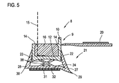
- Fig. 5 a further embodiment of a profile strip 8 according to the invention, in which case the profile body 9 has only the two side webs 10, 11, wherein on both side webs inwardly projecting lugs 14 are provided. It thus forms only a chamber which is completely filled with the plastic compound 16, which serves to fix the fabric strip 15.
- the fabric strip 15 extends here in the region of the inner side web 11.
- the elastic portion 21 is also designed here U-shaped, it has two side legs 22, 23 and the transverse leg 24.
- only the edge portion 27 is made tapered so that its edge 29 beyond the plane of the adhesive layer 31, again provided by a foam adhesive tape 32, is located.
- the edge portion 28 is ultimately not tapered running, in the mounting position, the edge 30 is not on the component. That is, the foam adhesive tape 32 is "sealed" from one side only.
- transverse web 12 and the transverse leg 24 extend here two intersecting connecting webs 38, which form the elastic, flexible elements 33, which allow the component movement.
Description
Die Erfindung betrifft eine Anschlussprofilleiste, insbesondere eine Laibungsanschlussprofilleiste.The invention relates to a connection profile strip, in particular a soffit connection profile strip.
Derartige Profilleisten dienen zumeist zur Herstellung eines Übergangs zwischen einem Fenster- oder Türrahmen oder einer Rolloschiene und der daran anschließenden Wand, wobei bekannte Anschlussprofile entweder eingeputzt werden, oder aber der Aufnahme von Verkleidungsplatten oder dergleichen dienen. Um zum einen einen optisch sauberen Übergang zum Tür- oder Fensterrahmen zu gewährleisten, und andererseits einen dichten Übergang zu bewerkstelligen, um zu verhindern, dass insbesondere bei einer Verwendung der Profilleiste im Außenbereich durch Schlagregen oder dergleichen bedingt Feuchtigkeit in den Übergangsbereich wandern kann, ist aus
Die Flexibilität des weich-elastischen Abschnitts lässt sowohl eine Verformung dieses Abschnitts in vertikaler sowie in horizontaler Richtung zu, worüber etwaige Mauer- oder Bauteilbewegungen kompensiert werden können. Bei einer horizontalen Bewegung wird der weich-elastische Abschnitt relativ zum Profilkörper gestaucht oder gedehnt, bei einer horizontalen Bewegung wird er quasi quer zum Profilkörper seitlich nach links oder rechts verschoben. Aufgabe der vorliegenden Erfindung ist es, eine Anschlussprofilleiste dahingehend zu verbessern, dass eine noch größere Beweglichkeit des weich-elastischen Abschnitts, insbesondere in quer- oder horizontaler Richtung, gegeben ist.The flexibility of the soft-elastic portion allows both a deformation of this portion in the vertical and in the horizontal direction, about which any wall or component movements can be compensated. In a horizontal movement of the soft-elastic portion is compressed or stretched relative to the profile body, in a horizontal movement, it is moved almost transversely to the profile body laterally to the left or right. Object of the present invention is to improve a connection profile strip to the effect that an even greater mobility of the soft-elastic portion, in particular in the transverse or horizontal direction, is given.
Zur Lösung dieses Problems ist erfindungsgemäß eine Anschlussprofilleiste, insbesondere eine Laibungsanschlussprofilleiste vorgesehen, mit einem Profikörper mit zwei Seitenstegen und einem diese verbindenden Quersteg, sowie einem aus einem weichen Kunststoffmaterial bestehen, im Wesentlichen U-förmigen Abschnitt, der aus zwei Seitenschenkeln und einem diese verbindenden Querschenkel besteht, wobei der Profilkörper in den U-förmigen Abschnitt eingesetzt ist und die beiden Seitenschenkel an der Außenseite der Seitenstege befestigt sind, wobei zwischen dem Quersteg und dem Querschenkel wenigstens ein flexibles Element vorgesehen ist, und wobei zumindest der Kantenabschnitt, in dem der Querschenkel und der in der Montagestellung außen liegende Seitenschenkel des U-förmigen Abschnitts zusammenlaufen, spitz ausläuft, so dass die Kante in oder jenseits der Ebene einer unterhalb des Querschenkels befindlichen Klebeschichten liegt.To solve this problem, the invention provides a connection profile strip, in particular a soffit connection profile strip provided with a profiled body with two side bars and a crosspiece connecting them, as well as one made of a soft plastic material, substantially U-shaped portion consisting of two side legs and a transverse leg connecting them consists, wherein the profile body is inserted into the U-shaped portion and the two side legs are attached to the outside of the side webs, wherein between the transverse web and the transverse leg at least one flexible element is provided, and wherein at least the edge portion in which the transverse leg and the side legs of the U-shaped section lying outside in the assembly position converge pointedly, so that the edge lies in or beyond the plane of an adhesive layer located below the transverse leg.
Anders als in der aus dem beschriebenen Stand der Technik bekannten Leiste ist bei der erfindungsgemäßen Anschlussprofilleiste der quasi U-förmige weil zwei Seitenstege aufweisende Profilkörper in den ebenfalls im Wesentlichen U-förmigen weich-elastischen Abschnitt eingesetzt, d. h., dass die Seitenschenkel des U-förmigen weich-elastischen Abschnitts bis in den Bereich seitlich der Seitenstege des Profilkörpers gezogen und an deren Außenseite befestigt sind. D. h., dass anders als im Stand der Technik die Seitenschenkel nicht an der Unterseite des Profilkörpers angeformt sind, sondern an den Außenseiten der Seitenstege. Sie können damit bei gleicher Bauhöhe länger ausgeführt werden, woraus eine größere Flexibilität respektive eine größere Verformbarkeit resultiert, insbesondere wenn die beiden Seitenschenkel unter einem Winkel zum jeweiligen Seitensteg verlaufen, also schräg zum Seitensteg hinlaufen. D. h., dass die Seitenschenkel quasi vom jeweiligen Seitensteg weg abstehen, woraus eine noch größere insbesondere horizontale Verschiebungsmöglichkeit resultiert.Unlike in the well-known from the prior art bar is in the terminal strip according to the invention of quasi U-shaped because two side bars having profile body inserted into the likewise substantially U-shaped soft-elastic portion, ie, that the side legs of the U-shaped soft-elastic portion drawn into the area laterally of the side webs of the profile body and secured to the outside thereof. That is to say that unlike in the prior art, the side legs are not formed on the underside of the profile body, but on the outer sides of the side webs. They can thus be made longer at the same height, resulting in greater flexibility and greater deformability, in particular if the two side legs extend at an angle to the respective side web, so run obliquely to the side web. In other words, the side legs virtually protrude away from the respective side web, resulting in an even larger, in particular horizontal, displacement possibility.
Um dem weich-elastischen U-förmigen Abschnitt eine ausreichende Stabilität bei gleichzeitig hoher Flexibilität zu verleihen, ist erfindungsgemäß weiterhin wenigstens ein zwischen dem Quersteg und dem Querschenkel befindliches flexibles Element vorgesehen, das ebenfalls aus weich-elastischem Kunststoffmaterial wie auch der Abschnitt selbst besteht, und das gleichermaßen einfach verformbar ist. Nachdem schließlich auch der in der Montagestellung außen liegende Seitenschenkel des weich-elastischen Abschnitts mit dem Querschenkel spitz ausläuft und sich die Kante in oder jenseits der Klebeschichtebene befindet, ist für einen sehr dichten Anschluss Sorge getragen.In order to give the soft elastic U-shaped portion sufficient stability with high flexibility, according to the invention further provided at least one located between the transverse web and the transverse leg flexible element, which also consists of soft-elastic plastic material as well as the section itself, and which is equally easily deformable. Finally, after the outer side leg of the soft-elastic portion in the mounting position with the transverse leg expires pointed and the edge is in or beyond the adhesive layer, care is taken for a very tight connection.
Wenngleich die Möglichkeit besteht, nur den Kantenabschnitt im Bereich der Leistenaußenseite spitz auslaufen zu lassen respektive die Kante jenseits der Klebeschichtebene zu positionieren, ist dies selbstverständlich auch an der gegenüberliegenden Leistenkante möglich, d. h., dass auch der Kantenabschnitt, in dem der Querschenkel und der in der Montagestellung innen liegende Seitenschenkel des U-förmigen Abschnitts zusammenlaufen, spitz ausläuft, so dass auch die dortige Kante in oder jenseits der Ebene einer unterhalb des Querschenkels befindlichen Klebeschicht liegt. Folglich wird ein sehr dichter Abschluss an beiden Kanten erreicht, so dass beispielsweise ein Schaumstoffklebeband, das auf den Querschenkel aufgeklebt ist und die Klebeschicht aufweist, von beiden Seiten her "abgedichtet" ist.Although it is possible to allow only the edge portion in the area of the strip outside to taper pointedly or to position the edge beyond the adhesive layer plane, this is of course also possible on the opposite strip edge, d. h., That also the edge portion, in which converge the transverse leg and in the assembled position inside leg of the U-shaped portion, runs out sharply, so that the local edge lies in or beyond the plane of an adhesive layer located below the transverse leg. As a result, a very tight seal is achieved at both edges, so that, for example, a foam adhesive tape adhered to the transverse leg and having the adhesive layer is "sealed" from both sides.
Das flexible Element, das sich zwischen Querschenkel und Quersteg befindet, ist bevorzugt als Schlaufe ausgebildet, die quasi eine elliptische Form aufweist und an die Unterseite des Quersteges sowie an die Oberseite des Querschenkels angeformt ist. Die Schlaufenform führt dazu, dass sich seitliche gebogene Verbindungsabschnitte ergeben, die vom Querschenkel zum Quersteg verlaufen. Diese Ausgestaltung ermöglicht eine abrollartige Bewegung, wenn der Querschenkel horizontal bzw. parallel zum Quersteg verschoben wird, was weiterhin der Vergrößerung der horizontalen Beweglichkeit, insbesondere in Verbindung mit einer schräg verlaufenden Anordnung der Seitenschenkel des U-förmigen weich-elastischen Abschnitts, zuträglich ist. Denkbar wäre aber auch, anstelle einer geschlossenen Schlaufe beispielsweise zwei separate Verbindungsstege vorzusehen, die gebogen ausgeführt sind, und die gleichermaßen eine abrollartige Bewegung ermöglichen. Weiterhin ist es selbstverständlich möglich, das flexible Element auch als einfachen Verbindungssteg, der vom Quersteg zum Querschenkel läuft, auszuführen, wie auch zwei oder mehr solche Verbindungsstege vorgesehen sein können, die sich gegebenenfalls auch kreuzen können.The flexible element, which is located between transverse leg and transverse web, is preferably designed as a loop, which has an elliptical shape and is formed on the underside of the transverse web as well as on the upper side of the transverse leg. The loop shape causes lateral curved connecting portions, which extend from the transverse leg to the crosspiece. This embodiment allows a roll-like movement when the transverse leg is displaced horizontally or parallel to the crossbar, which further the increase in horizontal mobility, especially in conjunction with an oblique arrangement of the side legs of the U-shaped soft-elastic portion, is beneficial. It would also be conceivable, for example, instead of a closed loop to provide two separate connecting webs, which are executed bent, and equally allow a roll-like movement. Furthermore, it is of course possible to perform the flexible element as a simple connecting web, which runs from the crosspiece to the transverse leg, as well as two or more such connecting webs may be provided, which may optionally also intersect.
Wie bereits beschrieben, laufen die beiden Seitenschenkel des weich-elastischen U-förmigen Abschnitts bevorzugt unter einem Winkel zum jeweiligen Seitensteg, wobei es jedoch erfindungsgemäß bereits ausreichend ist, wenn nur der in der Montagestellung außen liegende Seitenschenkel schräg verläuft.As already described, the two side legs of the soft-elastic U-shaped section preferably run at an angle to the respective side web, but it is already sufficient according to the invention if only the side leg lying outside in the assembly position runs obliquely.
In Weiterbildung der Erfindung kann schließlich vorgesehen sein, dass am Profilkörper zwischen die Seitenstege oder zwischen einen Seitensteg und einen am Profilkörper vorgesehenen mittleren Steg ein vom Profilkörper abstehender Gewebestreifen und eine diesen am Profilkörper fixierende, vorzugsweise weich-elastische Kunststoffmasse eingebracht ist. Ein solcher Gewebestreifen dient der festen Einbettung und Verbindung zur nach Montage der Leiste aufgebrachten Putzschicht. Er ist aus dem harten Kunststoffmaterial bestehenden Profilkörper fixiert, wozu eine Kunststoffmasse, die bevorzugt ebenfalls aus weich-elastischem Material ist, so dass sie ohne Weiteres bei der Leistenherstellung in diese offene Profilkörperkammer eingespritzt werden kann, dient. Die Kunststoffmasse kann je nach Ausgestaltung des Profilkörpers entweder den gesamten Bereich zwischen den beiden Seitenstegen ausfüllen, wobei der Gewebestreifen dann bevorzugt am in der Montagestellung innen liegenden Seitensteg vorgesehen wäre. Denkbar ist aber auch, am Profilkörper zusätzlich einen mittleren Steg vorzusehen, wobei bevorzugt die Kunststoffmasse in die in der Montagestellung hintere offene Kammer zwischen dem hinteren Seitensteg und dem mittleren Steg eingebracht ist, und der Gewebestreifen an der Hinterseite des mittleren Stegs verlaufend positioniert ist.In a further development of the invention may finally be provided that the profiled body between the side bars or between a side bar and provided on the profile body central web a projecting from the profile body fabric strip and this is fixed to the profile body, preferably soft elastic plastic material is introduced. Such a fabric strip is used for solid embedding and connection to the applied after mounting the bar plaster layer. It is fixed from the hard plastic material existing profile body, including a plastic mass, which is preferably also made of soft-elastic material, so that it can be easily injected in the ingot production in this open profile body chamber serves. Depending on the configuration of the profile body, the plastic compound can either fill the entire area between the two side webs, wherein the fabric strip would then preferably be provided on the side web which is located in the assembly position. It is also conceivable, however, to additionally provide a central web on the profile body, the plastic mass preferably being introduced into the rear open chamber between the rear side web and the middle web in the assembly position, and the fabric web is positioned to extend at the rear side of the middle web.
Die Elastizität der Kunststoffmasse ermöglicht eine gewisse Nachgiebigkeit, wenn aufgrund von Bauteilbewegungen eine Kraft auf den Verbindungsbereich des Gewebes und der Leiste wirkt, so dass das Gewebe nicht ab- oder herausgerissen werden kann. Die offene, die Kunststoffmasse aufnehmende Kammer kann bevorzugt über wenigstens eine seitlich vorspringende Nase, die an einem Seitensteg oder dem mittleren Steg angeformt ist, hinterschnitten sein. Alternativ zu dieser Befestigungsmöglichkeit kann der Gewebestreifen z.B. auch mittels eines geeigneten Klebemittels an einem Steg oder sonstigen Leistenabschnitt angeklebt werden. Alternativ ist auch eine Fixierung durch Annähen des Gewebestreifens denkbar, wie der Gewebestreifen auch durch Verschweißen mit der Leiste fest verbunden werden kann.The elasticity of the plastic compound allows a certain flexibility, if a force acts on the connection region of the tissue and the strip due to component movements, so that the tissue can not be torn off or torn off. The open, the plastic mass-receiving chamber may preferably be undercut via at least one laterally projecting nose, which is integrally formed on a side web or the central web. As an alternative to this mounting option, the fabric strip may be e.g. also be glued by means of a suitable adhesive to a web or other strip section. Alternatively, a fixation by sewing the fabric strip is conceivable as the fabric strip can be firmly connected by welding to the bar.
Die Klebeschicht, die der Fixierung der Anschlussprofilleiste dient, kann entweder am Querschenkel direkt aufgebracht sein, denkbar ist aber auch die Verwendung eines doppelseitigen Schaumstoffklebebandes, das mit einer Klebeschicht auf den Querschenkel aufgeklebt ist, die andere Klebeschicht dient der Leistenfixierung. Alternativ zur Aufbringung der Klebeschicht oder Anklebung des Schaumstoffklebebands direkt auf den Querschenkel ist es auch denkbar, an dem Querschenkel eine diesen versteifende, dünne Leiste bevorzugt aus hartem Kunststoffmaterial vorzusehen, auf welche die Klebeschicht oder das Schaumstoffklebeband aufgebracht ist.The adhesive layer, which serves to fix the connection profile strip, can either be applied directly to the transverse limb, but it is also conceivable to use a double-sided foam adhesive tape which is glued to the transverse limb with an adhesive layer, the other adhesive layer serves to fix the strips. As an alternative to applying the adhesive layer or gluing the foam adhesive tape directly to the transverse limb, it is also conceivable to provide a thin strip, preferably made of hard plastic material, to which the adhesive layer or the foam adhesive tape is applied to the transverse limb.
Der Profilkörper und gegebenenfalls die versteifende Leiste ist bevorzugt aus Hart-PVC, während der flexible Abschnitt und gegebenenfalls die Kunststoffmasse aus Weich-PVC, einem thermoplastischen Elastomer (TPE) oder einem anderen hinreichend weichen bzw. flexiblen Kunststoff ist. Der Profilkörper und gegebenenfalls die Leiste sowie der U-förmige Abschnitt und gegebenenfalls die Kunststoffmasse sind bevorzugt in einem Coextrusionsverfahren aneinandergeformt. Beispielsweise ist es denkbar, in einem ersten Coextrusionsschritt den Profilkörper und den U-förmigen Abschnitt aneinander zu spritzen, wonach der Gewebestreifen positioniert und die Kunststoffmasse eingespritzt wird, wobei gegebenenfalls sämtliche Verfahrensvorgänge auch in einem einzigen Coextrusionsverfahrensschritt durchgeführt werden können.The profile body and optionally the stiffening strip is preferably made of rigid PVC, while the flexible portion and optionally the plastic mass of soft PVC, a thermoplastic elastomer (TPE) or other sufficiently soft or flexible plastic. The profile body and optionally the strip and the U-shaped section and optionally the plastic compound are preferably molded together in a co-extrusion process. For example, it is conceivable in a first coextrusion step to spray the profile body and the U-shaped section together, after which the fabric strip is positioned and the plastic compound is injected, it being possible for all process operations to be carried out in a single coextrusion process step.
Schließlich kann vorgesehen sein, dass an der Außenseite des in der Montagestellung außen liegenden Seitenstegs oberhalb der Befestigungsstelle des Seitenschenkels ein Folienanklebesteg angeformt ist. Dieser über eine Sollbruchstelle abbrechbare Steg dient der Fixierung einer das Fenster oder die Tür während des Einputzvorgangs schützenden Folie. Der Folienanklebesteg ist bevorzugt etwas unterhalb der Endkante des Seitensteges angeformt, damit der Putz beim Einputzen der Leiste entlang dieses Seitensteges sauber abgezogen werden kann und der Folienanklebesteg hierbei nicht stört.Finally, it can be provided that on the outside of the side web lying in the mounting position above the attachment point of the side leg, a Folienanklebesteg is formed. This rupture over a predetermined breaking point web is used to fix a window or the door during the Einputzvorgangs protective film. The Folienanklebesteg is preferably formed slightly below the end edge of the side bar, so that the plaster during plastering of the bar along this side bar can be removed clean and the Folienanklebesteg does not bother.
Weiter Vorteile, Merkmale und Einzelheiten der Erfindung ergeben sich aus den im Folgenden beschriebenen Ausführungsbeispielen sowie anhand der Zeichnungen. Dabei zeigen:
- Fig. 1
- eine erfindungsgemäße Anschlussprofilleiste in Form eines Laibungsanschlussprofils in montierter Stellung,
- Fig. 2
- eine erfindungsgemäße Anschlussprofilleiste einer ersten Ausführungsform,
- Fig. 3
- eine erfindungsgemäße Anschlussprofilleiste einer zweiten Ausführungsform,
- Fig. 4
- eine erfindungsgemäße Anschlussprofilleiste einer dritten Ausführungsform und
- Fig. 5
- eine erfindungsgemäße Anschlussprofilleiste einer vierten Ausführungsform.
- Fig. 1
- a connection profile strip according to the invention in the form of a reveal connection profile in the mounted position,
- Fig. 2
- a connection profile strip according to the invention of a first embodiment,
- Fig. 3
- a connection profile strip according to the invention of a second embodiment,
- Fig. 4
- a connection profile strip according to the invention a third embodiment and
- Fig. 5
- a connection profile strip according to the invention of a fourth embodiment.
Weiterhin ist an der Außenseite des Seitensteges 10 ein Folienanklebesteg 18 angeformt, der über eine Materialschwächung 19 nach Beendigung des Einputzvorgangs abgebrochen werden kann. Der Folienanklebesteg 18 verfügt über eine Klebeschicht 20, beispielsweise gebildet durch ein Schaumstoffklebeband, auf welches die Folie aufgeklebt werden kann.Furthermore, a
Die Anschlussprofilleiste 8 umfasst ferner einen U-förmigen Abschnitt 21, bestehend aus zwei Seitenschenkeln 22 (dem in der Montagestellung außen liegenden Seitenschenkel) und 23 (dem innen liegenden Seitenschenkel) sowie einem diese verbindenden Querschenkel 24. Der U-förmige weich-elastische Abschnitt 21 besteht beispielsweise aus Weich-PVC. Wie
Weiterhin ist zwischen der Unterseite des Quersteges 12 und der Oberseite des Querschenkels 24 ein flexibles Element 33 vorgesehen, das Teil des Abschnitts 21 ist bzw. mit diesem einstückig verbunden ist und als Schlaufe 34 ausgeführt ist. Es ist an der einen Seite fest mit dem leicht nach innen gewölbten Quersteg 12 und an der andere Seite einstückig mit dem Querschenkel 24 verbunden. Die Schlaufe ist hohl und elliptischer Form, so dass sich beidseits gebogene Verbindungsstege bilden.Furthermore, a
Die erfindungsgemäße Form des elastischen Abschnitts 21 mit seinen schräg verlaufenden Seitenschenkeln 22, 23 in Verbindung mit dem schlaufenförmigen elastischen Element 33 ermöglicht einen sehr flexiblen und sowohl in vertikaler wie auch in horizontaler Richtung eine große Bewegungsfreiheit ermöglichenden Aufbau, mit dem auch relativ große Bauteilbewegungen ohne Ablösung der Verklebung oder Putzanbindung kompensiert werden können. Denn die relativ langen weil bis knapp in die Mitte oder über die Mitte der jeweiligen Seitenflächen 25, 26 der Seitenstege 10, 11 gezogene Befestigungsposition der Seitenschenkel 22, 23 und daraus resultierend ihre beachtliche Länge und ihr schräger Verlauf lassen eine beachtliche Horizontalbewegung zu, der auch die gebogenen Verbindungsabschnitte der Schlaufe 34 ohne Weiteres abrollartig folgen.The inventive shape of the
Zwischen Querschenkel 24 und Quersteg 12 erstrecken sich hier zwei flexible Elemente 33 in Form gerade Verbindungsstege 37, die wie auch die gebogenen Verbindungsstege 35 einstückig mit dem Querschenkel 24 sind und folglich ebenfalls aus weich-elastischem Material wie Weich-PVC sind. Auch diese Stege sind hinreichend flexibel, um eine vertikale wie auch horizontale Bewegung zu ermöglichen.Between
Schließlich zeigt
Zwischen dem Quersteg 12 und dem Querschenkel 24 verlaufen hier zwei sich kreuzende Verbindungsstege 38, die die elastischen, flexiblen Elemente 33 bilden, die die Bauteilbewegung ermöglichen.Between the
An dieser Stelle ist darauf hinzuweisen, dass die beschriebenen unterschiedlichen Ausgestaltungen selbstverständlich nicht abschließend sind. So können die verschiedenen gezeigten Profilkörper 9 wie auch die Geometrie der etwaigen Verbindungsstege zwischen dem Quersteg 12 und dem Querschenkel 24 auch andersartig sein. Auch können am Profikörper noch weitere Verankerungsmöglichkeiten oder Einputzhilfen vorgesehen sein. Ferner können auch andere Kunststoffe als PVC verwendet werden.It should be noted at this point that the described different embodiments are of course not exhaustive. Thus, the
Claims (11)
- Connection profile, in particular a reveal connection profile, having a profile body (9) having two lateral webs (10, 11) and an interconnecting transverse web (12), and having a substantially U-shaped portion (21) composed of a soft plastic material, which is composed of two lateral legs (22, 23) and an interconnecting transverse leg (24), wherein the profile body (9) is inserted into the U-shaped portion (21) and the two lateral legs (22, 23) are fastened on the outer sides (25, 26) of the lateral webs (10, 11), wherein between the transverse web (12) and the transverse leg (24) at least one flexible element (33) is provided, and wherein at least the edge portion (27), in which the transverse leg (24) and the lateral leg (22) of the U-shaped portion (21), which in the mounting position lies outboard, converge, tapers off in a pointed manner, such that the edge (29) lies in or beyond the plane of an adhesive layer (31) which is situated below the transverse leg (24).
- Connection profile according to Claim 1, characterized in that also the edge portion (28), in which the transverse leg (24) and the lateral leg (11) of the U-shaped portion (21), which in the mounting position lies inboard, converge, tapers off in a pointed manner, such that the edge (30) lies in or beyond the plane of the adhesive layer (31) which is situated below the transverse leg (24).
- Connection profile according to Claim 1 or 2, characterized in that the flexible element (33) is implemented as a loop (34) which is tied to the transverse web (12) and to the transverse leg (24), or as a connecting web (35, 37, 38) which runs from the transverse web (12) to the transverse leg (24).
- Connection profile according to Claim 3, characterized in that two or more connecting webs (35, 37, 38) which optionally intersect and/or are implemented in a curved manner are provided.
- Connection profile according to one of the preceding claims, characterized in that at least the lateral leg (22) which in the mounting position lies outboard, preferably both the lateral legs (22, 23), runs/run at an angle in relation to the respective lateral web (10, 11).
- Connection profile according to one of the preceding claims, characterized in that a fabric strip (1), which projects from the profile body (9), and a plastic compound (16) which fixes said fabric strip (1) on the profile body (9), are incorporated on the profile body (9) between the lateral webs (10, 11), or between one lateral web (10, 11) and a central web (13) which is provided on the profile body (9).
- Connection profile according to Claim 6, characterized in that on at least one lateral web (10, 11) or the central web (13) a laterally protruding catch (14) is provided.
- Connection profile according to one of the preceding claims, characterized in that an adhesive tape (32) which displays the adhesive layer (31) is disposed on the transverse leg (24) or on a cleat (36) which stiffens the transverse leg (24), or in that the adhesive layer (31) is directly applied onto the transverse leg (24) or the cleat (36).
- Connection profile according to one of the preceding claims, characterized in that the profile body (9) and optionally the cleat (36) are of unplasticized PVC, and the flexible portion (21) and optionally the plastic compound (16) are of plasticized PVC, a thermoplastic elastomer (TPE) or another sufficiently flexible plastic.
- Connection profile according to one of the preceding claims, characterized in that the profile body (9) and optionally the cleat (36) and the U-shaped portion (21) and optionally the plastic compound (16) are moulded onto one another in a co-extrusion process.
- Connection profile according to one of the preceding claims, characterized in that a web (18) for adhesively attaching a film is moulded onto the outer side (25) of the lateral web (10), which in the mounting position lies outboard, above the fastening point of the lateral leg (22).
Priority Applications (1)
| Application Number | Priority Date | Filing Date | Title |
|---|---|---|---|
| PL10164508T PL2273037T3 (en) | 2009-06-04 | 2010-05-31 | Connection profile, in particular reveal connection profile |
Applications Claiming Priority (1)
| Application Number | Priority Date | Filing Date | Title |
|---|---|---|---|
| DE102009023958A DE102009023958B3 (en) | 2009-06-04 | 2009-06-04 | Connection profile strip, in particular soffit connection profile strip |
Publications (3)
| Publication Number | Publication Date |
|---|---|
| EP2273037A2 EP2273037A2 (en) | 2011-01-12 |
| EP2273037A3 EP2273037A3 (en) | 2014-09-03 |
| EP2273037B1 true EP2273037B1 (en) | 2015-01-28 |
Family
ID=42710770
Family Applications (1)
| Application Number | Title | Priority Date | Filing Date |
|---|---|---|---|
| EP10164508.3A Not-in-force EP2273037B1 (en) | 2009-06-04 | 2010-05-31 | Connection profile, in particular reveal connection profile |
Country Status (3)
| Country | Link |
|---|---|
| EP (1) | EP2273037B1 (en) |
| DE (1) | DE102009023958B3 (en) |
| PL (1) | PL2273037T3 (en) |
Families Citing this family (5)
| Publication number | Priority date | Publication date | Assignee | Title |
|---|---|---|---|---|
| DE102011004769A1 (en) * | 2011-02-25 | 2012-08-30 | August Braun | Plastering bar and building corner with plaster molding |
| AT13185U1 (en) * | 2012-07-02 | 2013-08-15 | AF Tec Beteiligungs GmbH | Laying connection profile for plaster adjacent components |
| EP3037617B1 (en) * | 2014-12-23 | 2019-04-24 | Weroform GmbH | Plastering strip with support feet |
| DE102015121431A1 (en) * | 2015-12-09 | 2017-06-14 | Roman Zahner | Connection profile strip, in particular soffit connection profile strip |
| AT523847B1 (en) * | 2021-02-01 | 2021-12-15 | K Uni Kunststoffproduktions Und Handels Gmbh | CONNECTION PROFILE FOR COMPONENTS ADJACENT TO PLASTER |
Family Cites Families (3)
| Publication number | Priority date | Publication date | Assignee | Title |
|---|---|---|---|---|
| DE102005022826B4 (en) * | 2005-05-12 | 2010-04-15 | Roman Zahner | Connection profile strip, in particular soffit connection profile strip |
| DE102007009945A1 (en) * | 2007-03-01 | 2008-09-04 | Tremco Illbruck Produktion Gmbh | Cleaning strip for door or window frames has a frame-fastening limb in a cross-section crosswise to the frame-fastening limb and bridge sections extending over a base section with a clearance from each other |
| DE102007032081B4 (en) * | 2007-07-09 | 2012-07-26 | Roman Zahner | Connection profile strip, in particular soffit connection profile strip |
-
2009
- 2009-06-04 DE DE102009023958A patent/DE102009023958B3/en not_active Expired - Fee Related
-
2010
- 2010-05-31 PL PL10164508T patent/PL2273037T3/en unknown
- 2010-05-31 EP EP10164508.3A patent/EP2273037B1/en not_active Not-in-force
Also Published As
| Publication number | Publication date |
|---|---|
| EP2273037A3 (en) | 2014-09-03 |
| PL2273037T3 (en) | 2015-07-31 |
| EP2273037A2 (en) | 2011-01-12 |
| DE102009023958B3 (en) | 2010-12-16 |
Similar Documents
| Publication | Publication Date | Title |
|---|---|---|
| EP2404007B1 (en) | Profiled strip comprising a sealing device for sealing a joint between two building components | |
| WO1989004897A1 (en) | Protective lath making a plaster joint when plastering a wall | |
| EP1722064B1 (en) | Connecting section member, in particular reveal connecting member | |
| EP2492428B1 (en) | Staff angle and building corner with staff angle | |
| EP2273037B1 (en) | Connection profile, in particular reveal connection profile | |
| EP1801309A2 (en) | Profile for compensation of movements | |
| EP0892143B1 (en) | Sealing for windows, doors and facades | |
| EP1956158A2 (en) | Connection profile, in particular plastering profile | |
| AT501438B1 (en) | LOCATION CONNECTION PROFILE FOR COMPONENTS TO BE ADJUSTED TO PUTZ | |
| AT8398U1 (en) | TWO-PIECE PERMANENT CONNECTION PROFILE | |
| DE102005012537B3 (en) | Profile rail for inner face of window or door opening has U-section rail with adhesive on inner face to connect to main frame member | |
| DE202005016524U1 (en) | Cleaning strip and rolled-up plaster molding | |
| EP0877143B1 (en) | Sealing strip | |
| DE102007032081B4 (en) | Connection profile strip, in particular soffit connection profile strip | |
| DE2752463A1 (en) | Plastics, hollow, profiled, foam-filled, window frame part - has sealing lip pressed against glass pane by strip spring fitted in lengthwise groove | |
| DE2755321A1 (en) | SEALING STRIPS FOR WINDOWS OR DOORS | |
| DE202006009790U1 (en) | Two-part reveal connecting profile for window and door posts has base profile and external profile made of flexible material supplied in rolls with fixing arm of external profile insertable between component and resilient retaining web | |
| EP2206870A2 (en) | Connecting moulded part, in particular reveal connecting moulded part | |
| AT506154B1 (en) | TWO-PIECE PERMANENT CONNECTION PROFILE | |
| DE202009013120U1 (en) | One-piece plaster molding and transition between two components of a building | |
| EP3179024A1 (en) | Connecting moulded part, in particular embrasure connecting moulded part | |
| EP3473782A1 (en) | Connection profile for components bordering plaster | |
| DE102010051274A1 (en) | Silicone tape for elastic sealing of joints | |
| EP0638698B1 (en) | Edge-protecting border | |
| DE202008006947U1 (en) | Elastic profile for sealing joints |
Legal Events
| Date | Code | Title | Description |
|---|---|---|---|
| PUAI | Public reference made under article 153(3) epc to a published international application that has entered the european phase |
Free format text: ORIGINAL CODE: 0009012 |
|
| AK | Designated contracting states |
Kind code of ref document: A2 Designated state(s): AL AT BE BG CH CY CZ DE DK EE ES FI FR GB GR HR HU IE IS IT LI LT LU LV MC MK MT NL NO PL PT RO SE SI SK SM TR |
|
| AX | Request for extension of the european patent |
Extension state: BA ME RS |
|
| PUAL | Search report despatched |
Free format text: ORIGINAL CODE: 0009013 |
|
| AK | Designated contracting states |
Kind code of ref document: A3 Designated state(s): AL AT BE BG CH CY CZ DE DK EE ES FI FR GB GR HR HU IE IS IT LI LT LU LV MC MK MT NL NO PL PT RO SE SI SK SM TR |
|
| AX | Request for extension of the european patent |
Extension state: BA ME RS |
|
| RIC1 | Information provided on ipc code assigned before grant |
Ipc: E04F 13/06 20060101AFI20140730BHEP Ipc: E06B 1/62 20060101ALI20140730BHEP |
|
| GRAP | Despatch of communication of intention to grant a patent |
Free format text: ORIGINAL CODE: EPIDOSNIGR1 |
|
| 17P | Request for examination filed |
Effective date: 20141008 |
|
| RBV | Designated contracting states (corrected) |
Designated state(s): AL AT BE BG CH CY CZ DE DK EE ES FI FR GB GR HR HU IE IS IT LI LT LU LV MC MK MT NL NO PL PT RO SE SI SK SM TR |
|
| RIC1 | Information provided on ipc code assigned before grant |
Ipc: E06B 1/62 20060101ALI20141020BHEP Ipc: E04F 13/06 20060101AFI20141020BHEP |
|
| INTG | Intention to grant announced |
Effective date: 20141104 |
|
| GRAS | Grant fee paid |
Free format text: ORIGINAL CODE: EPIDOSNIGR3 |
|
| GRAA | (expected) grant |
Free format text: ORIGINAL CODE: 0009210 |
|
| AK | Designated contracting states |
Kind code of ref document: B1 Designated state(s): AL AT BE BG CH CY CZ DE DK EE ES FI FR GB GR HR HU IE IS IT LI LT LU LV MC MK MT NL NO PL PT RO SE SI SK SM TR |
|
| REG | Reference to a national code |
Ref country code: GB Ref legal event code: FG4D Free format text: NOT ENGLISH |
|
| REG | Reference to a national code |
Ref country code: CH Ref legal event code: EP |
|
| REG | Reference to a national code |
Ref country code: IE Ref legal event code: FG4D Free format text: LANGUAGE OF EP DOCUMENT: GERMAN |
|
| REG | Reference to a national code |
Ref country code: DE Ref legal event code: R096 Ref document number: 502010008805 Country of ref document: DE Effective date: 20150312 |
|
| REG | Reference to a national code |
Ref country code: AT Ref legal event code: REF Ref document number: 708322 Country of ref document: AT Kind code of ref document: T Effective date: 20150315 |
|
| REG | Reference to a national code |
Ref country code: NL Ref legal event code: VDEP Effective date: 20150128 |
|
| REG | Reference to a national code |
Ref country code: LT Ref legal event code: MG4D |
|
| PG25 | Lapsed in a contracting state [announced via postgrant information from national office to epo] |
Ref country code: NO Free format text: LAPSE BECAUSE OF FAILURE TO SUBMIT A TRANSLATION OF THE DESCRIPTION OR TO PAY THE FEE WITHIN THE PRESCRIBED TIME-LIMIT Effective date: 20150428 Ref country code: SE Free format text: LAPSE BECAUSE OF FAILURE TO SUBMIT A TRANSLATION OF THE DESCRIPTION OR TO PAY THE FEE WITHIN THE PRESCRIBED TIME-LIMIT Effective date: 20150128 Ref country code: HR Free format text: LAPSE BECAUSE OF FAILURE TO SUBMIT A TRANSLATION OF THE DESCRIPTION OR TO PAY THE FEE WITHIN THE PRESCRIBED TIME-LIMIT Effective date: 20150128 Ref country code: ES Free format text: LAPSE BECAUSE OF FAILURE TO SUBMIT A TRANSLATION OF THE DESCRIPTION OR TO PAY THE FEE WITHIN THE PRESCRIBED TIME-LIMIT Effective date: 20150128 Ref country code: BG Free format text: LAPSE BECAUSE OF FAILURE TO SUBMIT A TRANSLATION OF THE DESCRIPTION OR TO PAY THE FEE WITHIN THE PRESCRIBED TIME-LIMIT Effective date: 20150428 Ref country code: FI Free format text: LAPSE BECAUSE OF FAILURE TO SUBMIT A TRANSLATION OF THE DESCRIPTION OR TO PAY THE FEE WITHIN THE PRESCRIBED TIME-LIMIT Effective date: 20150128 Ref country code: LT Free format text: LAPSE BECAUSE OF FAILURE TO SUBMIT A TRANSLATION OF THE DESCRIPTION OR TO PAY THE FEE WITHIN THE PRESCRIBED TIME-LIMIT Effective date: 20150128 |
|
| REG | Reference to a national code |
Ref country code: PL Ref legal event code: T3 |
|
| PG25 | Lapsed in a contracting state [announced via postgrant information from national office to epo] |
Ref country code: NL Free format text: LAPSE BECAUSE OF FAILURE TO SUBMIT A TRANSLATION OF THE DESCRIPTION OR TO PAY THE FEE WITHIN THE PRESCRIBED TIME-LIMIT Effective date: 20150128 Ref country code: GR Free format text: LAPSE BECAUSE OF FAILURE TO SUBMIT A TRANSLATION OF THE DESCRIPTION OR TO PAY THE FEE WITHIN THE PRESCRIBED TIME-LIMIT Effective date: 20150429 Ref country code: LV Free format text: LAPSE BECAUSE OF FAILURE TO SUBMIT A TRANSLATION OF THE DESCRIPTION OR TO PAY THE FEE WITHIN THE PRESCRIBED TIME-LIMIT Effective date: 20150128 Ref country code: IS Free format text: LAPSE BECAUSE OF FAILURE TO SUBMIT A TRANSLATION OF THE DESCRIPTION OR TO PAY THE FEE WITHIN THE PRESCRIBED TIME-LIMIT Effective date: 20150528 |
|
| REG | Reference to a national code |
Ref country code: DE Ref legal event code: R097 Ref document number: 502010008805 Country of ref document: DE |
|
| PG25 | Lapsed in a contracting state [announced via postgrant information from national office to epo] |
Ref country code: RO Free format text: LAPSE BECAUSE OF FAILURE TO SUBMIT A TRANSLATION OF THE DESCRIPTION OR TO PAY THE FEE WITHIN THE PRESCRIBED TIME-LIMIT Effective date: 20150128 Ref country code: SK Free format text: LAPSE BECAUSE OF FAILURE TO SUBMIT A TRANSLATION OF THE DESCRIPTION OR TO PAY THE FEE WITHIN THE PRESCRIBED TIME-LIMIT Effective date: 20150128 Ref country code: DK Free format text: LAPSE BECAUSE OF FAILURE TO SUBMIT A TRANSLATION OF THE DESCRIPTION OR TO PAY THE FEE WITHIN THE PRESCRIBED TIME-LIMIT Effective date: 20150128 Ref country code: EE Free format text: LAPSE BECAUSE OF FAILURE TO SUBMIT A TRANSLATION OF THE DESCRIPTION OR TO PAY THE FEE WITHIN THE PRESCRIBED TIME-LIMIT Effective date: 20150128 |
|
| PGFP | Annual fee paid to national office [announced via postgrant information from national office to epo] |
Ref country code: HU Payment date: 20150521 Year of fee payment: 6 |
|
| REG | Reference to a national code |
Ref country code: HU Ref legal event code: AG4A Ref document number: E024736 Country of ref document: HU |
|
| PLBE | No opposition filed within time limit |
Free format text: ORIGINAL CODE: 0009261 |
|
| STAA | Information on the status of an ep patent application or granted ep patent |
Free format text: STATUS: NO OPPOSITION FILED WITHIN TIME LIMIT |
|
| REG | Reference to a national code |
Ref country code: CH Ref legal event code: PL |
|
| 26N | No opposition filed |
Effective date: 20151029 |
|
| GBPC | Gb: european patent ceased through non-payment of renewal fee |
Effective date: 20150531 |
|
| PG25 | Lapsed in a contracting state [announced via postgrant information from national office to epo] |
Ref country code: LI Free format text: LAPSE BECAUSE OF NON-PAYMENT OF DUE FEES Effective date: 20150531 Ref country code: LU Free format text: LAPSE BECAUSE OF FAILURE TO SUBMIT A TRANSLATION OF THE DESCRIPTION OR TO PAY THE FEE WITHIN THE PRESCRIBED TIME-LIMIT Effective date: 20150531 Ref country code: MC Free format text: LAPSE BECAUSE OF FAILURE TO SUBMIT A TRANSLATION OF THE DESCRIPTION OR TO PAY THE FEE WITHIN THE PRESCRIBED TIME-LIMIT Effective date: 20150128 Ref country code: CH Free format text: LAPSE BECAUSE OF NON-PAYMENT OF DUE FEES Effective date: 20150531 |
|
| REG | Reference to a national code |
Ref country code: IE Ref legal event code: MM4A |
|
| PG25 | Lapsed in a contracting state [announced via postgrant information from national office to epo] |
Ref country code: SI Free format text: LAPSE BECAUSE OF FAILURE TO SUBMIT A TRANSLATION OF THE DESCRIPTION OR TO PAY THE FEE WITHIN THE PRESCRIBED TIME-LIMIT Effective date: 20150128 |
|
| PG25 | Lapsed in a contracting state [announced via postgrant information from national office to epo] |
Ref country code: IE Free format text: LAPSE BECAUSE OF NON-PAYMENT OF DUE FEES Effective date: 20150531 Ref country code: GB Free format text: LAPSE BECAUSE OF NON-PAYMENT OF DUE FEES Effective date: 20150531 |
|
| REG | Reference to a national code |
Ref country code: FR Ref legal event code: PLFP Year of fee payment: 7 |
|
| PGFP | Annual fee paid to national office [announced via postgrant information from national office to epo] |
Ref country code: IT Payment date: 20160524 Year of fee payment: 7 |
|
| PG25 | Lapsed in a contracting state [announced via postgrant information from national office to epo] |
Ref country code: MT Free format text: LAPSE BECAUSE OF FAILURE TO SUBMIT A TRANSLATION OF THE DESCRIPTION OR TO PAY THE FEE WITHIN THE PRESCRIBED TIME-LIMIT Effective date: 20150128 |
|
| PG25 | Lapsed in a contracting state [announced via postgrant information from national office to epo] |
Ref country code: HU Free format text: LAPSE BECAUSE OF NON-PAYMENT OF DUE FEES Effective date: 20160601 |
|
| REG | Reference to a national code |
Ref country code: FR Ref legal event code: PLFP Year of fee payment: 8 |
|
| PG25 | Lapsed in a contracting state [announced via postgrant information from national office to epo] |
Ref country code: SM Free format text: LAPSE BECAUSE OF FAILURE TO SUBMIT A TRANSLATION OF THE DESCRIPTION OR TO PAY THE FEE WITHIN THE PRESCRIBED TIME-LIMIT Effective date: 20150128 |
|
| PG25 | Lapsed in a contracting state [announced via postgrant information from national office to epo] |
Ref country code: CY Free format text: LAPSE BECAUSE OF FAILURE TO SUBMIT A TRANSLATION OF THE DESCRIPTION OR TO PAY THE FEE WITHIN THE PRESCRIBED TIME-LIMIT Effective date: 20150128 |
|
| PG25 | Lapsed in a contracting state [announced via postgrant information from national office to epo] |
Ref country code: BE Free format text: LAPSE BECAUSE OF NON-PAYMENT OF DUE FEES Effective date: 20150531 |
|
| PG25 | Lapsed in a contracting state [announced via postgrant information from national office to epo] |
Ref country code: TR Free format text: LAPSE BECAUSE OF FAILURE TO SUBMIT A TRANSLATION OF THE DESCRIPTION OR TO PAY THE FEE WITHIN THE PRESCRIBED TIME-LIMIT Effective date: 20150128 |
|
| REG | Reference to a national code |
Ref country code: FR Ref legal event code: PLFP Year of fee payment: 9 |
|
| PG25 | Lapsed in a contracting state [announced via postgrant information from national office to epo] |
Ref country code: IT Free format text: LAPSE BECAUSE OF NON-PAYMENT OF DUE FEES Effective date: 20170531 |
|
| PG25 | Lapsed in a contracting state [announced via postgrant information from national office to epo] |
Ref country code: MK Free format text: LAPSE BECAUSE OF FAILURE TO SUBMIT A TRANSLATION OF THE DESCRIPTION OR TO PAY THE FEE WITHIN THE PRESCRIBED TIME-LIMIT Effective date: 20150128 Ref country code: PT Free format text: LAPSE BECAUSE OF FAILURE TO SUBMIT A TRANSLATION OF THE DESCRIPTION OR TO PAY THE FEE WITHIN THE PRESCRIBED TIME-LIMIT Effective date: 20150128 |
|
| PGFP | Annual fee paid to national office [announced via postgrant information from national office to epo] |
Ref country code: CZ Payment date: 20180518 Year of fee payment: 9 |
|
| PGFP | Annual fee paid to national office [announced via postgrant information from national office to epo] |
Ref country code: FR Payment date: 20180523 Year of fee payment: 9 Ref country code: PL Payment date: 20180528 Year of fee payment: 9 Ref country code: AT Payment date: 20180517 Year of fee payment: 9 |
|
| PG25 | Lapsed in a contracting state [announced via postgrant information from national office to epo] |
Ref country code: AL Free format text: LAPSE BECAUSE OF FAILURE TO SUBMIT A TRANSLATION OF THE DESCRIPTION OR TO PAY THE FEE WITHIN THE PRESCRIBED TIME-LIMIT Effective date: 20150128 |
|
| REG | Reference to a national code |
Ref country code: AT Ref legal event code: MM01 Ref document number: 708322 Country of ref document: AT Kind code of ref document: T Effective date: 20190531 |
|
| PG25 | Lapsed in a contracting state [announced via postgrant information from national office to epo] |
Ref country code: AT Free format text: LAPSE BECAUSE OF NON-PAYMENT OF DUE FEES Effective date: 20190531 Ref country code: CZ Free format text: LAPSE BECAUSE OF NON-PAYMENT OF DUE FEES Effective date: 20190531 |
|
| PG25 | Lapsed in a contracting state [announced via postgrant information from national office to epo] |
Ref country code: FR Free format text: LAPSE BECAUSE OF NON-PAYMENT OF DUE FEES Effective date: 20190531 |
|
| PGFP | Annual fee paid to national office [announced via postgrant information from national office to epo] |
Ref country code: DE Payment date: 20200513 Year of fee payment: 11 |
|
| REG | Reference to a national code |
Ref country code: DE Ref legal event code: R119 Ref document number: 502010008805 Country of ref document: DE |
|
| PG25 | Lapsed in a contracting state [announced via postgrant information from national office to epo] |
Ref country code: PL Free format text: LAPSE BECAUSE OF NON-PAYMENT OF DUE FEES Effective date: 20190531 |
|
| PG25 | Lapsed in a contracting state [announced via postgrant information from national office to epo] |
Ref country code: DE Free format text: LAPSE BECAUSE OF NON-PAYMENT OF DUE FEES Effective date: 20211201 |