EP2264342A2 - Plattenventil - Google Patents
Plattenventil Download PDFInfo
- Publication number
- EP2264342A2 EP2264342A2 EP10165627A EP10165627A EP2264342A2 EP 2264342 A2 EP2264342 A2 EP 2264342A2 EP 10165627 A EP10165627 A EP 10165627A EP 10165627 A EP10165627 A EP 10165627A EP 2264342 A2 EP2264342 A2 EP 2264342A2
- Authority
- EP
- European Patent Office
- Prior art keywords
- valve
- plate
- actuating
- connection flange
- actuating device
- Prior art date
- Legal status (The legal status is an assumption and is not a legal conclusion. Google has not performed a legal analysis and makes no representation as to the accuracy of the status listed.)
- Granted
Links
Images
Classifications
-
- F—MECHANICAL ENGINEERING; LIGHTING; HEATING; WEAPONS; BLASTING
- F16—ENGINEERING ELEMENTS AND UNITS; GENERAL MEASURES FOR PRODUCING AND MAINTAINING EFFECTIVE FUNCTIONING OF MACHINES OR INSTALLATIONS; THERMAL INSULATION IN GENERAL
- F16K—VALVES; TAPS; COCKS; ACTUATING-FLOATS; DEVICES FOR VENTING OR AERATING
- F16K1/00—Lift valves or globe valves, i.e. cut-off apparatus with closure members having at least a component of their opening and closing motion perpendicular to the closing faces
- F16K1/24—Lift valves or globe valves, i.e. cut-off apparatus with closure members having at least a component of their opening and closing motion perpendicular to the closing faces with valve members that, on opening of the valve, are initially lifted from the seat and next are turned around an axis parallel to the seat
Definitions
- the present invention relates to a plate valve according to the preamble of claim 1.
- a plate valve is known with a housing having a first connection flange with a first opening for mounting on a container or plant to be evacuated and a second connection flange with a second opening for mounting a vacuum source, preferably a vacuum pump, such as diffusion pump, turbomolecular pump and like.
- the second opening is formed on the side facing away from the second flange as a valve seat, which can be closed by a movable valve plate.
- a third connection flange is provided, which is closed by a cap.
- an actuating device is arranged, which has an axially displaceable actuating member. The distal end of the axially displaceable actuator is secured to the plate valve.
- the valve plate is raised by a certain distance, so that a passage between the first and second opening is created.
- valve plate in the open state of the valve, the valve plate is located in the space between the first and second flange and thereby affects the conductance. This problem could only be solved by further raising the valve plate so that it would be practically outside the opening area of the first connection flange. However, this required an even longer actuator, which would make the known plate valve even bulkier. To achieve a reasonable compromise between these conflicting requirements, the valve plate is therefore raised so far that it is located approximately at 2/3 of the clear height of the first opening.
- Object of the present invention is to provide a plate valve available, which allows a maximum conductance. Another goal is to propose a plate valve, which has a small footprint. Yet another aim is to provide a plate valve which is simple in construction and can be manufactured at low cost.
- the object is achieved with a plate valve according to the preamble of claim 1, characterized in that the third connection flange is arranged with the actuator axially opposite the first connection flange, and the actuating device has a linearly displaceable in a displacement direction actuator.
- the arrangement of the actuator directly opposite the valve seat has the advantage that only a linearly displaceable actuator for the execution of Schliess- resp. Opening movement is necessary. Accordingly, the plate valve is easy and inexpensive to produce. By a rectilinear closing movement and a large closing force can be applied, so that a reliable seal between the valve plate and the valve seat can be done.
- the actuating device preferably has a pivoting mechanism, which is coupled to the linearly displaceable actuating member and designed such that during the linear displacement of the actuating member, a pivoting movement is generated.
- This has the advantage that by a linear movement and a pivoting movement of the valve plate can be effected. the plate valve is very low, since a pivoting movement of the valve plate has a smaller space requirement than if the valve plate would be moved only linearly.
- the pivoting mechanism is formed by a lever arrangement.
- a lever arrangement is structurally simple and inexpensive to produce.
- the pivoting mechanism is formed by a link arrangement.
- the gate arrangement has the advantage that Guideways, which come about by a superposition of a rotary and a linear movement, are very easy and reliable to implement.
- the second connection flange extends in a plane which is orthogonal to the plane of the pivoted valve plate. This has the advantage that the valve plate is positioned in the passage between the first and second connection flange so that the conductance is not significantly affected.
- the actuator is articulated hinged to the valve plate and pivotable about a first pivot axis relative to the valve plate. This has the effect that the valve plate can perform both a linear and a rotational movement.
- a holder is expediently arranged on the inside of the housing oriented side of the valve plate, with a first articulation point for the actuator and a second articulation point spaced from the first articulation point for a pivotable actuating lever.
- the first end of the actuating lever is advantageously pivotable about a second pivot axis defined by the second pivot point and the second end by a third stationary pivot axis.
- a lever is advantageously produced on the holder, by means of which the rotary movement of the valve plate in the desired direction is made possible.
- the holder is advantageously formed by two spaced-apart webs, which webs rise vertically from the valve plate. As a result, the holder has sufficient stability in order to reliably transmit the movement forces of the actuating member to the valve plate.
- a support is preferably provided, on which the actuating lever is articulated.
- the support is expediently supported either on the housing or on the actuating device. If the support is based on the actuating device, then no moving parts are directly or indirectly connected to the housing.
- the actuator is so removable together with all moving parts of the housing. This significantly facilitates maintenance and repair work, as all moving parts are easily accessible.
- a slot is provided at the first end of the actuating lever. This has the advantage that a circular movement of the actuating lever is made possible and at the same time the holder is pivotable by the actuating lever.
- the actuating device is arranged in the housing. This has the advantage that the plate valve is built very compact, without having additional attachments or elevations on its housing outer wall.
- a convexly curved cap is provided, on which the actuating device is arranged inside.
- the actuator protrudes only slightly into the passage between the first and the second flange and affects the conductance only slightly.
- the domed cap closes the third flange.
- the domed cap together with all moving parts can be removed from the housing.
- the valve cover has sufficient stability to pressure differences caused by a high vacuum on the low pressure side and normal pressure in the valve housing, the lid is preferably curved inwards.
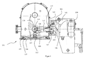
- FIG. 1 a plate valve 101 is shown which has been on the market for several years.
- the plate valve has a housing 102, which through an inlet opening (in FIG. 1 not shown), through which atmosphere is drawn, and through an outlet opening 119, through which atmosphere the plate valve 101 leaves, is weakened.
- an actuating device 103 is provided on the lateral surface of the housing 102.
- the actuator 103 deflects via an actuator 104 to an L-shaped lever 105.
- the actuator 104 is connected to the L-shaped lever 105 at the end of its shorter leg 106.
- a passage opening 108 is provided at the end of the longer leg 107.
- valve cover 114 At the beginning of the rotational movement of the L-shaped lever 105 counterclockwise performs the valve cover 114, articulated by the web 113, a nearly linear movement, which moves him away from its valve seat 115.
- a guide lever 116 During the linear movement of the valve cover 114 is additionally articulated by a guide lever 116.
- the guide lever 116 is hinged to a support 117 via a stationary pivot axis 120.
- the support 117 is fixedly connected to the cylinder jacket of the housing 102.
- valve cover 114 Following the nearly linear movement of the valve cover 114 is in a pivoting movement in the counterclockwise direction. In this case, the valve cover 114 rotates about a mobile pivot axis 118, which is provided on the valve cover 114 facing away from the end of the web 113. During the almost linear movement of the valve cover 114th When the mobile pivot axis 118 moves in a circular path about the stationary pivot axis 120, during the pivotal movement of the valve cover 114, the position of the mobile pivot axis 118 relative to the stationary pivot axis 120 is fixed.
- valve cover 114 is further articulated by the L-shaped lever 105 and the web 113, wherein during the pivoting movement of the bolt 112 rotates in the through hole 108.
- the plate valve 101 has a favorable conductance, which is achieved by the plate valve 101 in the open position of a gas flow, which moves from an inlet opening to an outlet opening 119, only a small resistance.
- the plate valve 101 As disadvantages of the plate valve 101 are directly recognizable its complicated structure with a large number of moving parts and the large footprint of the actuator 104. As a result, the present plate valve is expensive to manufacture. Furthermore, maintenance or repair work is complicated because it is not possible to remove the L-shaped lever 105 together with the valve cover 114 from the housing 102 without removing the housing 102 from the overall pumping station.
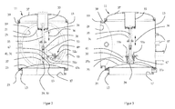
- FIGS. 2 and 3 show a plate valve 11 according to the invention with a housing 13.
- a first connection flange 15 with a first opening 17 and a second connection flange 19 are provided with a second opening 21.
- the first connection flange 15 serves to connect to a low-pressure side, for example the connection of a vacuum pump.
- the plate valve 11 is connected, for example, with a chamber to be evacuated.
- the second connection flange 19 z. B. be connected to be evacuated vacuum chamber.
- At the first opening 17 side facing away from a valve seat 23 is provided.
- the valve seat 23 cooperates with a valve plate 25 to gas-tightly separate the first connection flange 15 from the second connection flange 19.
- the valve plate 25 is formed as a domed inside the housing 13 lid. By this curved design, a deflection of the valve plate 25 is prevented when the valve is closed, when normal pressure in the valve body and high vacuum prevails on the low pressure side.
- a holder 27 is centrally arranged, on which an actuating member 35 of an actuating device 33 is articulated.
- the diaphragm bellows 34 can join in the movement of the actuator.
- the sealing of the actuating device can take place via a radial seal.
- the actuating member 35 is in communication with the actuating device 33 and is linearly displaceable by the latter in a displacement direction 36.
- the actuating device 33 is formed by a piston / cylinder unit 33 which is pneumatically actuated.
- the piston / cylinder unit is arranged inside the housing 13 and centrally on an outwardly curved cap 37.
- the domed cap 37 is fixed to a third connection flange 39 of the housing 13.
- the curvature of the cap 37 allows the partial accommodation of the piston / cylinder unit 33, so that this only slightly into the passage between the first and the second flange 15,19 protrudes. This has the advantage that the conductance is not significantly affected by the actuator 33.
- the holder 27 and the actuating member 35 are pivotable about a first pivot point 30 extending through a first pivot point 29.
- a pivoting of the valve plate 25 and the holder 27 arranged thereon is effected in the axial displacement of the actuating member 33 by a stationary actuating lever 43, which is articulated with a first end at a distance from the first articulation point 29 at a second articulation point 31 on the holder 27.
- a second pivot axis 41 is defined.
- With its second end of the actuating lever 43 is articulated to a fixed support 49 (third pivot axis 47), which is supported on the inner wall of the housing 13.
- the holder 27 is formed by two spaced apart webs 27a, b, which protrude perpendicularly from the valve plate 25.
- the two webs are connected by a bolt 28.
- the bolt 28 extends through a circular hole at the end of the actuator 35.
- the actuating lever 43a, b hinged (In FIG. 3 only the operating lever 43a can be seen).
- the actuating lever 43a, b are in turn articulated with their second ends to an adjusting device.
- the adjusting device is formed by two levers 51 a, b, which are arranged displaceably on the support 49.
- the levers 51a, b have two elongated holes 52a, b, through which two fixing screws are guided.
- a strut 55 connects the support 49 to the actuator 35 to stabilize and guide the latter.
- a sleeve 56 is arranged on the strut 55, through which the actuating member 35 extends.
- flanges 57 On the outer wall of the housing 13, a plurality of flanges 57 is provided.
- the flanges 57 are used, for example, to accommodate probes, valves or sight glasses.
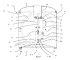
- FIG. 4 shows a preferred embodiment, in which the support 49 is supported on the actuating device 33.
- the support 49 is formed by a rod 59, which is attached at one end via a mounting plate 61 directly to the actuator 33.
- the other end of the rod 59 is connected to the actuator 35 similarly to the first embodiment.
- This embodiment has the advantage that all parts of the actuating mechanism are arranged on the curved cap 37 and can be pulled out of the housing 13 with the cap 37. A maintenance or replacement of all moving parts can be done very quickly and easily.
- the plate valve 11 functions as follows: A vacuum pump connected to the first connection flange 15 evacuates a chamber connected to the second connection flange 19. During the evacuation process, the valve plate 25 is in an open position (In FIG. 2 shown in dashed lines). In the open position, the plane of the valve plate 25 is orthogonal to the plane in which the second connection flange 19 is located.
- the conductance of the inventive plate valve is very high, since the extracted atmosphere, which enters the housing 13 through the second opening 21 and leaves the housing 13 via the first opening 17, practically no attack surfaces within the housing 13 finds.
- the valve plate 25 is in the open position at an angle of attack relative to the air flow, which generates the least possible resistance.
- the actuator 33 is largely outside the air flow. Other components that are within the air flow have only small surfaces and thus contribute to a high conductance.
- the piston / cylinder unit 33 is pressurized with compressed air.
- the actuator 35 is displaced linearly in the direction of displacement 36 from the piston / cylinder unit 33.
- the actuating lever 43 is supported on the fixed support 53 during the linear movement of the actuating member 35 with its second end.
- the first end of the operating lever 43 rotates around the third stationary pivot axis 47 in a counterclockwise direction.
- the actuating lever 43 pivots the holder 27 and the valve plate 25 also counterclockwise.
- the valve plate 25 rotates about the first pivot axis 30.
- an axle pin moves in the slot 45 during pivoting of the holder 27, the slot 45 acts as a backdrop and the axle pin as a sliding block.
- the valve plate 25 is forcibly pivoted further with progressive linear movement of the actuating member 35 in the direction of the first opening 17 via the actuating lever.
- the lengths of the operating lever 43, the holder 27 and the support 49 are dimensioned exactly so that the valve plate is in a horizontal position when the actuating lever 43 is oriented horizontally. In this position, the valve plate 25 is located at a short distance centrally above the valve seat 23.
- By a final linear lowering the valve plate 25 is moved to a closed position. In the closed position, the valve plate 25 is pressed by the actuator 35 fixed to the valve seat 23. The procedure described above is performed vice versa to move the valve plate back to the open position.
- One idea of the invention is that the linear movement of the actuating member 35 by the actuating lever 43 in a first step in a positively driven rotational Movement of the valve plate 25 is transformed and in a second step, the valve plate 25 is moved linearly over a short distance.
- the inventive plate valve 11 it is important that the lengths of the holder 27, the operating lever 43 and support 49, and the position of the first, second and third pivot axis 30,41,47 are coordinated.
- the plate valve 11 is very low and its height exceeds only slightly the diameter of the second flange 19. The low height is achieved in that the valve plate 25 is not linearly removed from the flow area, but remains in the flow area and pivoted to a position with optimum conductance becomes.
- the closing or opening mechanism is of simple construction and inexpensive to manufacture.
Landscapes
- Engineering & Computer Science (AREA)
- General Engineering & Computer Science (AREA)
- Mechanical Engineering (AREA)
- Sliding Valves (AREA)
- Details Of Valves (AREA)
- Reciprocating Pumps (AREA)
- Check Valves (AREA)
- Details Of Reciprocating Pumps (AREA)
- Mechanically-Actuated Valves (AREA)
Abstract
Description
- Die vorliegende Erfindung betrifft ein Plattenventil gemäss Oberbegriff von Anspruch 1.
- Im Stand der Technik ist ein Plattenventil bekannt mit einem Gehäuse mit einem ersten Anschlussflansch mit einer ersten Öffnung zur Montage an einem zu evakuierenden Behälter oder Anlage und einem zweiten Anschlussflansch mit einer zweiten Öffnung zur Montage einer Unterdruckquelle, vorzugsweise einer Vakuumpumpe, wie Diffusionspumpe, Turbomolekularpumpe und dergleichen. Die zweite Öffnung ist an der dem zweiten Anschlussflansch abgewandten Seite als Ventilsitz ausgebildet, welcher durch eine bewegliche Ventilplatte verschliessbar ist. Axial gegenüberliegend zum zweiten Anschlussflansch ist ein dritter Anschlussflansch vorgesehen, welcher durch eine Kappe verschlossen ist. In der Kappe ist eine Betätigungseinrichtung angeordnet, welche ein axial verschiebbares Betätigungsorgan besitzt. Das distale Ende des axial verschiebbaren Betätigungsorgans ist am Plattenventil festgemacht. Zum Öffnen des Plattenventils wird die Ventilplatte um eine bestimmte Distanz angehoben, sodass ein Durchgang zwischen der ersten und zweiten Öffnung geschaffen ist.
- Nachteilig am beschriebenen Ventil ist, dass im Offenzustand des Ventils die Ventilplatte sich im Raum zwischen dem ersten und zweiten Anschlussflansch befindet und den Leitwert dadurch beeinträchtigt. Dieses Problem könnte nur dadurch gelöst werden, dass die Ventilplatte noch weiter angehoben würde, sodass diese sich praktisch ausserhalb es Öffnungsbereichs des ersten Anschlussflansches befinden würde. Dies erforderte jedoch ein noch längeres Betätigungsorgan, wodurch das bekannte Plattenventil noch sperriger würde. Um einen vernünftigen Kompromiss zwischen diesen gegenläufigen Anforderungen zu erzielen, wird die Ventilplatte daher soweit angehoben, dass diese ungefähr auf 2/3 der lichten Höhe des ersten Öffnung befindet.
- Es befindet sich auf dem Markt ein Plattenventil, bei dem ein Betätigungsorgan den Ventildeckel über ein aufwändiges Hebelsystem zuerst nahezu linear vom Ventilsitz abhebt und anschliessend um 90 Grad verschwenkt. Dieses Plattenventil besitzt einen günstigen Leitwert, ist jedoch kompliziert aufgebaut und teuer in der Herstellung. Ferner benötigt das Betätigungsorgan viel Platz. Erwähntes Plattenventil ist in der Einleitung der Figurenbeschreibung detailliert beschrieben.
- Aufgabe der vorliegenden Erfindung ist es, ein Plattenventil zur Verfügung zu stellen, welches einen maximalen Leitwert ermöglicht. Ein weiteres Ziel ist es, ein Plattenventil vorzuschlagen, welches einen geringen Platzbedarf hat. Noch ein Ziel ist es, ein Plattenventil bereitzustellen, welches einfach aufgebaut und mit geringen Kosten herstellbar ist.
- Dieses und weitere Ziele werden durch die Merkmale des Patentanspruchs 1 gelöst. Vorteilhafte Ausführungsformen sind in den Unteransprüchen definiert.
- Erfindungsgemäss wird die Aufgabe bei einem Plattenventil gemäss Oberbegriff des Patentanspruchs 1 dadurch gelöst, dass der dritte Anschlussflansch mit der Betätigungseinrichtung axial gegenüber dem ersten Anschlussflansch angeordnet ist, und die Betätigungseinrichtung ein in einer Verschieberichtung linear verschiebbares Betätigungsorgan aufweist. Die Anordnung der Betätigungseinrichtung direkt gegenüberliegend dem Ventilsitz hat den Vorteil, dass lediglich ein linear verschiebbares Betätigungsorgan für die Ausführung der Schliess- resp. Öffnungsbewegung nötig ist. Entsprechend ist das Plattenventil einfach und kostengünstig herstellbar. Durch eine geradlinige Schliessbewegung kann auch eine grosse Schliesskraft aufgebracht werden, sodass eine zuverlässige Dichtung zwischen der Ventilplatte und dem Ventilsitz erfolgen kann.
- Die Betätigungseinrichtung besitzt vorzugsweise einen Verschwenkmechanismus, welcher mit dem linear verschiebbaren Betätigungsorgan gekoppelt und derart ausgebildet ist, dass bei der linearen Verschiebung des Betätigungsorgans eine Schwenkbewegung erzeugt wird. Dies hat den Vorteil, dass durch eine Linearbewegung auch eine Schwenkbewegung der Ventilplatte bewirkt werden kann. das Plattenventil sehr niedrig baut, da eine Schwenkbewegung der Ventilplatte einen geringeren Raumbedarf aufweist, als wenn die Ventilplatte ausschliesslich linear bewegt werden würde.
- Zweckmässigerweise ist der Verschwenkmechanismus durch eine Hebelanordnung gebildet. Eine Hebelanordnung ist konstruktiv einfach und kostengünstig herstellbar.
- In einer besonders bevorzugten Ausführungsvariante ist der Verschwenkmechanismus durch eine Kulissenanordnung gebildet. Die Kulissenanordnung hat den Vorteil, dass Führungsbahnen, welche durch eine Überlagerung von einer rotatorischen und einer linearen Bewegung zustande kommen, sehr einfach und zuverlässig realisierbar sind.
- Vorteilhaft erstreckt sich der zweite Anschlussflansch in einer Ebene, welche orthogonal zur Ebene der verschwenkten Ventilplatte steht. Dies hat den Vorteil, dass die Ventilplatte in dem Durchgang zwischen dem ersten und zweiten Anschlussflansch so positioniert, dass der Leitwert nicht wesentlich beeinträchtigt wird.
- Vorteilhaft ist das Betätigungsorgan gelenkig an der Ventilplatte angelenkt und um eine erste Schwenkachse relativ zur Ventilplatte verschwenkbar. Dies hat den Effekt, dass die Ventilplatte sowohl eine lineare als auch eine rotatorische Bewegung ausführen kann.
- Damit die lineare Bewegung des Betätigungsorgans in eine Verschwenkbewegung transformiert wird, ist an der zum Gehäuseinneren orientierten Seite der Ventilplatte zweckmässigerweise ein Halter angeordnet, mit einem ersten Anlenkpunkt für das Betätigungsorgan und einem vom ersten Anlenkpunkt beabstandeten zweiten Anlenkpunkt für einen verschwenkbaren Betätigungshebel. Dabei ist das erste Ende des Betätigungshebels vorteilhaft um eine durch den zweiten Anlenkpunkt definierte zweite Schwenkachse und das zweite Ende durch eine dritte stationäre Schwenkachse verschwenkbar. Diese Konstruktionsmerkmale haben den Vorteil, dass die Ventilplatte über eine einfache Mechanik zwangsgeführt ist und ein einziger linearer Antrieb eine translatorische und eine rotatorische Bewegung generiert.
- Dadurch dass der zweite Anlenkpunkt weiter von der Ventilplatte entfernt ist als der erste Anlenkpunkt wird an dem Halter vorteilhaft ein Hebel erzeugt, durch den die Drehbewegung der Ventilplatte in die gewünschte Richtung ermöglicht ist.
- Der Halter ist mit Vorteil durch zwei voneinander beabstandete Stege gebildet, welche Stege sich senkrecht von der Ventilplatte erheben. Dadurch weist der Halter eine ausreichende Stabilität auf, um die Bewegungskräfte des Betätigungsorgans zuverlässig auf die Ventilplatte zu übertragen.
- Damit der Betätigungshebel an seinem zweiten Ende ausreichend gestützt ist, ist vorzugsweise ein Support vorgesehen, an welchem der Betätigungshebel angelenkt ist.
- Der Support stützt sich zweckmässigerweise entweder am Gehäuse oder an der Betätigungseinrichtung ab. Stützt sich der Support an der Betätigungseinrichtung ab, so stehen keine bewegten Teile direkt oder indirekt mit dem Gehäuse in Verbindung. Die Betätigungseinrichtung ist so gemeinsam mit allen bewegten Teilen aus dem Gehäuse entfernbar. Dies erleichtert Wartungs- und Reparaturarbeiten signifikant, da alle bewegten Teile leicht zugänglich sind.
- Vorteilhaft ist am ersten Ende des Betätigungshebels ein Langloch vorgesehen. Dies hat den Vorteil, dass eine Kreisbewegung des Betätigungshebels ermöglicht ist und gleichzeitig der Halter durch den Betätigungshebel verschwenkbar ist.
- In einer bevorzugten Ausführungsvariante ist die Betätigungseinrichtung im Gehäuse angeordnet. Dies hat den Vorteil, dass das Plattenventil sehr kompakt gebaut ist, ohne zusätzliche Anbauteile oder Erhebungen an seiner Gehäuseaussenwand aufzuweisen.
- Mit Vorteil ist eine konvex gewölbte Kappe vorgesehen, an welcher die Betätigungseinrichtung inwendig angeordnet ist. Dadurch ragt die Betätigungseinrichtung nur geringfügig in den Durchgang zwischen dem ersten und dem zweiten Anschlussflansch und beeinträchtigt den Leitwert nur unwesentlich.
- Damit eine besonders einfache und rasche Wartung des Plattenventils ermöglicht ist, verschliesst die gewölbte Kappe den dritten Anschlussflansch. Bei Wartungsarbeiten ist lediglich die Verbindung zum dritten Anschlussflansch zu lösen, dann ist die gewölbte Kappe mitsamt allen beweglichen Teilen aus dem Gehäuse entfernbar.
- Damit der Ventildeckel eine ausreichende Stabilität gegenüber Druckdifferenzen aufweist, die durch ein Hochvakuum auf der Niedrigdruckseite und Normaldruck im Ventilgehäuse entstehen, ist der Deckel vorzugsweise nach innen gewölbt.
- Nachfolgend wird die Erfindung unter die Bezugnahme auf die Figuren beispielhaft erläutert. Dabei werden in den verschiedenen Ausführungsbeispielen gleiche Teile mit gleichen Bezugsziffern bezeichnet. Es zeigt:
- Figur 1
- ein Plattenventil des Stands der Technik in einer Seitenansicht,
- Figur 2
- eine Frontansicht eines ersten Ausführungsbeispiels eines erfindungsgemässen Plattenventils,
- Figur 3
- eine Seitenansicht des Plattenventils aus
Figur 2 , und - Figur 4
- eine Frontansicht einer weiteren Ausführungsvariante des erfindungsgemässen Plattenventils.
- In
Figur 1 ist ein Plattenventil 101 dargestellt, welches sich seit mehreren Jahren auf dem Markt befindet. Das Plattenventil besitzt ein Gehäuse 102, welches durch eine Einlassöffnung (inFigur 1 nicht gezeigt), durch welche Atmosphäre angesaugt wird, und durch eine Auslassöffnung 119, durch welche Atmosphäre das Plattenventil 101 verlässt, verschwächt ist. An der Mantelfläche des Gehäuses 102 ist eine Betätigungseinrichtung 103 vorgesehen. Die Betätigungseinrichtung 103 lenkt über ein Betätigungsorgan 104 einen L-förmigen Hebel 105 an. Das Betätigungsorgan 104 ist mit dem L-förmigen Hebel 105 am Ende dessen kürzeren Schenkels 106 verbunden. Am Ende des längeren Schenkels 107 ist eine Durchgangsöffnung 108 vorgesehen. - Bewegt sich das Betätigungsorgan 104 in Richtung der Bewegungsrichtung 109 vertikal nach unten, wird der L-förmige Hebel 105 um eine stationäre Drehachse 110 gegen den Uhrzeigersinn verschwenkt. In der Durchgangsöffnung 108 des Schenkels 107 ist ein Bolzen 112 drehbar aufgenommen, welcher über einen Steg 113 mit einem Ventildeckel 114 gelenkig verbunden ist.
- Zu Beginn der Drehbewegung des L-förmigen Hebels 105 gegen den Uhrzeigersinn vollführt der Ventildeckel 114, angelenkt durch den Steg 113, eine nahezu lineare Bewegung, welche ihn von seinem Ventilsitz 115 weg bewegt. Während der Linearbewegung ist der Ventildeckel 114 zusätzlich durch einen Führungshebel 116 angelenkt. Der Führungshebel 116 ist an einem Support 117 über eine stationäre Schwenkachse 120 gelenkig gestützt. Der Support 117 ist fest mit dem Zylindermantel des Gehäuses 102 verbunden.
- Im Anschluss an die nahezu lineare Bewegung geht der Ventildeckel 114 in eine Verschwenkbewegung gegen den Uhrzeigersinn über. Dabei dreht sich der Ventildeckel 114 um eine mobile Schwenkachse 118, welche am dem Ventildeckel 114 abgewandten Ende des Stegs 113 vorgesehen ist. Während der nahezu linearen Bewegung des Ventildeckels 114 bewegt sich die mobile Schwenkachse 118 auf einer Kreisbahn um die stationäre Schwenkachse 120, während der Verschwenkbewegung des Ventildeckels 114 ist die Position der mobilen Schwenkachse 118 relativ zur stationären Schwenkachse 120 unveränderlich.
- Damit diese Verschwenkbewegung zustande kommt, wird der Ventildeckel 114 weiterhin durch den L-förmigen Hebel 105 und den Steg 113 angelenkt, wobei während der Verschwenkbewegung der Bolzen 112 in der Durchgangsöffnung 108 rotiert.
- Zur Führung der Verschwenkbewegung des Ventildeckels 114 um den Drehpunkt 118 ist der Steg 113 durch den Führungshebel 116 gehalten, der seinerseits durch den Support 117 gelenkig gehalten ist. Die Endstellung des Ventildeckels 114 nach der Verschwenkbewegung um 90 Grad ist in
Figur 1 strichliert dargestellt. Zum Schliessen des Plattenventils 101 wird der oben beschriebene Öffnungsvorgang vice versa durchgeführt. - Der fachkundige Leser erkennt, dass das Plattenventil 101 einen günstigen Leitwert besitzt, der dadurch zustande kommt, dass das Plattenventil 101 in der geöffneten Position einer Gasströmung, welche sich von einer Einlassöffnungen zu einer Auslassöffnung 119 bewegt, nur einen geringen Widerstand entgegensetzt.
- Als Nachteile des Plattenventils 101 sind unmittelbar dessen komplizierter Aufbau mit einer grossen Anzahl von bewegten Teilen und der grosse Platzbedarf des Betätigungsorgans 104 zu erkennen. Demzufolge ist das vorliegende Plattenventil in seiner Herstellung teuer. Ferner gestalten sich Wartungs- bzw. Reparaturarbeiten als aufwändig, da es nicht möglich ist, den L-förmigen Hebel 105 mitsamt dem Ventildeckel 114 aus dem Gehäuse 102 zu entfernen, ohne das Gehäuse 102 aus dem Gesamtpumpstand auszubauen.
- Die
Figuren 2 und 3 zeigen ein erfindungsgemässes Plattenventil 11 mit einem Gehäuse 13. An dem Gehäuse 13 sind ein erster Anschlussflansch 15 mit einer ersten Öffnung 17 und ein zweiter Anschlussflansch 19 mit einer zweiten Öffnung 21 vorgesehen. Der erste Anschlussflansch 15 dient der Verbindung zu einer Niedrigdruckseite, beispielsweise dem Anschluss einer Vakuumpumpe. An dem zweiten Anschlussflansch 19 ist das Plattenventil 11 beispielsweise mit einer zu evakuierenden Kammer verbunden. An dem zweiten Anschlussflansch 19 kann z. B. eine zu evakuierende Vakuumkammer angeschlossen sein. An der der ersten Öffnung 17 abgewandten Seite ist ein Ventilsitz 23 vorgesehen. Der Ventilsitz 23 wirkt mit einer Ventilplatte 25 zusammen, um den ersten Anschlussflansch 15 gegenüber dem zweiten Anschlussflansch 19 gasdicht zu trennen. Die Ventilplatte 25 ist als ein ins Innere des Gehäuses 13 gewölbter Deckel ausgebildet. Durch diese gewölbte Bauform ist ein Durchbiegen der Ventilplatte 25 bei geschlossenem Ventil verhindert, wenn im Ventilgehäuse Normaldruck und auf der Niedrigdruckseite Hochvakuum herrscht. - An der zum Gehäuseinneren orientierten Seite der Ventilplatte 25 ist mittig ein Halter 27 angeordnet, an welchem ein Betätigungsorgan 35 einer Betätigungseinrichtung 33 angelenkt ist. Die Abdichtung der Betätigungseinrichtung 33 gegenüber dem Gehäuseinneren erfolgt über einen Membranbalg 34. Der Membranbalg 34 kann die Bewegung des Betätigungsorgans mitmachen. Alternativ kann die Abdichtung der Betätigungseinrichtung über eine Radialdichtung erfolgen. Das Betätigungsorgan 35 steht mit der Betätigungseinrichtung 33 in Verbindung und ist durch diese in einer Verschieberichtung 36 linear verschieblich. Im gezeigten Ausführungsbeispiel ist die Betätigungseinrichtung 33 durch ein Kolben/Zylinderaggregat 33 gebildet, welches pneumatisch betätigbar ist. Denkbar wäre auch eine hydraulische oder elektrische Betätigung des Betätigungsorgans. Das Kolben/Zylinderaggregat ist innerhalb des Gehäuses 13 und mittig an einer nach aussen gewölbten Kappe 37 angeordnet. Die gewölbte Kappe 37 ist an einem dritten Anschlussflansch 39 des Gehäuses 13 befestigt. Die Wölbung der Kappe 37 erlaubt die teilweise Aufnahme des Kolben/Zylinderaggregats 33, sodass dieses nur geringfügig in den Durchgang zwischen dem ersten und dem zweiten Anschlussflansch 15,19 ragt. Dies hat den Vorteil, dass der Leitwert durch die Betätigungseinrichtung 33 nicht wesentlich beeinträchtigt wird.
- Der Halter 27 und das Betätigungsorgan 35 sind um eine durch einen ersten Anlenkpunkt 29 verlaufende erste Schwenkachse 30 verschwenkbar. Ein Verschwenken der Ventilplatte 25 und dem daran angeordnetem Halter 27 wird bei der Axialverschiebung des Betätigungsorgans 33 durch einen stationären Betätigungshebel 43 bewirkt, welcher mit einem ersten Ende in Abstand zum ersten Anlenkpunkt 29 an einem zweiten Anlenkpunkt 31 am Halter 27 angelenkt ist. Durch diesen zweiten Anlenkpunkt 31 ist eine zweite Schwenkachse 41 definiert. Mit seinem zweiten Ende ist der Betätigungshebel 43 an einem fixen Support 49 angelenkt (dritte Schwenkachse 47), welcher sich an der Innenwand des Gehäuses 13 abstützt. Wird nun die Ventilplatte 25 durch das Betätigungsorgan 35 von der in
Fig. 1 gezeigten Verschlussstellung angehoben, so wird der Halter 27 und damit die Ventilplatte 25 durch den Betätigungshebel 43 von der waagrechten Stellung in eine senkrechte Stellung verschwenkt (inFig. 1 strichliert eingezeichnet). Um eine Kreisbewegung des Betätigungshebels 43 zu ermöglichen, ist an dessen ersten Ende ein Langloch 45 vorgesehen, in welchem ein Achsstift verschieblich ist. - Im Ausführungsbeispiel gemäss
Figur 3 ist der Halter 27 durch zwei in Abstand von einander angeordnete Stege 27a,b gebildet, welche senkrecht von der Ventilplatte 25 abstehen. Die beiden Stege sind durch einen Bolzen 28 miteinander verbunden. Der Bolzen 28 erstreckt sich durch ein kreisförmiges Loch am Ende des Betätigungsorgans 35. An den beiden Stegen 27a,b sind die Betätigungshebel 43a,b angelenkt (InFigur 3 ist nur der Betätigungshebel 43a erkennbar). Die Betätigungshebel 43a,b sind ihrerseits mit ihren zweiten Enden an einer Justiereinrichtung angelenkt. Die Justiereinrichtung ist durch zwei Hebel 51a,b gebildet, die am Support 49 verschieblich angeordnet sind. Zu diesem Zweck weisen die Hebel 51a,b zwei Langlöcher 52a,b auf, durch welche zwei Fixierschrauben geführt sind. - Eine Strebe 55 verbindet den Support 49 mit dem Betätigungsorgan 35, um letzteres zu stabilisieren und zu führen. Zu diesem Zweck ist an der Strebe 55 eine Hülse 56 angeordnet, durch welche sich das Betätigungsorgan 35 erstreckt.
- An der Aussenwand des Gehäuses 13 ist eine Mehrzahl von Flanschen 57 vorgesehen. Die Flansche 57 dienen beispielsweise der Aufnahme von Messsonden, Ventilen oder Schaugläsern.
-
Figur 4 zeigt eine bevorzugte Ausführungsvariante, bei der der Support 49 an der Betätigungseinrichtung 33 abgestützt ist. In diesem Fall ist der Support 49 durch eine Stange 59 gebildet, welche an einem Ende über eine Befestigungsplatte 61 direkt an der Betätigungseinrichtung 33 befestigt ist. Das andere Ende der Stange 59 ist ähnlich wie in dem ersten Ausführungsbeispiel mit dem Betätigungsorgan 35 verbunden. - Diese Ausführungsvariante hat den Vorteil, dass alle Teile des Betätigungsmechanismus an der gewölbten Kappe 37 angeordnet sind und mit der Kappe 37, aus dem Gehäuse 13 herausziehbar sind. Eine Wartung oder ein Austausch aller bewegten Teile kann dadurch sehr rasch und einfach erfolgen.
- Das erfindungsgemässe Plattenventil 11 funktioniert wie folgt: Eine an dem ersten Anschlussflansch 15 angeschlossene Vakuumpumpe evakuiert eine an dem zweiten Anschlussflansch 19 angeschlossene Kammer. Während des Evakuierungsvorgangs befindet sich die Ventilplatte 25 in einer Offenstellung (In
Figur 2 strichliert dargestellt). In der Offenstellung steht die Ebene der Ventilplatte 25 orthogonal zur Ebene, in der sich der zweite Anschlussflansch 19 befindet. - Der Leitwert des erfindungsgemässen Plattenventils ist sehr hoch, da die abgesaugte Atmosphäre, welche durch die zweite Öffnung 21 in das Gehäuse 13 eintritt und das Gehäuse 13 über die erste Öffnung 17 verlässt, praktisch keine Angriffsflächen innerhalb des Gehäuses 13 vorfindet. Die Ventilplatte 25 steht in der Offenstellung in einem Anstellwinkel relativ zur Luftströmung, der den geringstmöglichen Widerstand generiert. Darüber hinaus liegt die Betätigungseinrichtung 33 grösstenteils ausserhalb der Luftströmung. Weitere Bauteile, welche sich innerhalb der Luftströmung befinden, besitzen nur kleine Oberflächen und tragen somit auch zu einem hohen Leitwert bei.
- Ist in der Kammer der gewünschte Unterdruck erreicht, so wird die Kolben/Zylindereinheit 33 mit Druckluft beaufschlagt. Das Betätigungsorgan 35 wird linear in Verschieberichtung 36 aus der Kolben/Zylindereinheit 33 herausverschoben. Der Betätigungshebel 43 stützt sich während der Linearbewegung des Betätigungsorgans 35 mit seinem zweiten Ende an dem fixen Support 53 ab. Das erste Ende des Betätigungshebels 43 bewegt sich rotatorisch um die dritte stationäre Schwenkachse 47 gegen den Uhrzeigersinn. Über den zweiten Anlenkpunkt 31, an dem der Betätigungshebel 43 beispielsweise mit einem Achsstift mit dem Halter 27 verbunden ist, verschwenkt der Betätigungshebel 43 den Halter 27 und die Ventilplatte 25 ebenfalls gegen den Uhrzeigersinn. Die Ventilplatte 25 rotiert dabei um die erste Schwenkachse 30. Um eine Kreisbewegung des Betätigungshebels 43 zu ermöglichen, verschiebt sich ein Achsstift in dem Langloch 45 während der Verschwenkung des Halters 27, wobei das Langloch 45 als Kulisse und der Achsstift als Kulissenstein fungiert.
- Die Ventilplatte 25 wird mit fortschreitender Linearbewegung des Betätigungsorgans 35 in Richtung der ersten Öffnung 17 über den Betätigungshebel weiter zwangsverschwenkt. Die Längen des Betätigungshebels 43, des Halters 27 und des Supports 49 sind genau so dimensioniert, dass die Ventilplatte sich in horizontaler Lage befindet, wenn der Betätigungshebel 43 horizontal ausgerichtet ist. In dieser Position befindet sich die Ventilplatte 25 in kurzem Abstand zentrisch oberhalb des Ventilsitzes 23. Durch ein abschliessendes lineares Absenken wird die Ventilplatte 25 in eine Verschlussstellung bewegt. In der Verschlussstellung wird die Ventilplatte 25 von dem Betätigungsorgan 35 fest auf den Ventilsitz 23 gepresst. Der oben beschriebene Vorgang wird vice versa durchgeführt, um die Ventilplatte wieder in die Offenstellung zu bewegen.
- Ein Gedanke der Erfindung liegt darin, dass die Linearbewegung des Betätigungsorgans 35 durch den Betätigungshebel 43 in einem ersten Schritt in eine zwangsgeführte rotatorische Bewegung der Ventilplatte 25 transformiert wird und in einem zweiten Schritt die Ventilplatte 25 über eine kurze Distanz linear bewegt wird. Bei dem erfindungsgemässen Plattenventil 11 ist es von Bedeutung, dass die Längen von Halter 27, Betätigungshebel 43 und Support 49, sowie die Position der ersten, zweiten und dritten Schwenkachse 30,41,47 aufeinander abgestimmt sind.
- Das Plattenventil 11 baut sehr niedrig und seine Höhe übersteigt nur unwesentlich den Durchmesser des zweiten Anschlussflansches 19. Die niedrige Bauhöhe wird dadurch erreicht, dass die Ventilplatte 25 nicht linear aus dem Durchströmungsbereich entfernt wird, sondern im Durchströmungsbereich verbleibt und in eine Position mit optimalem Leitwert verschwenkt wird. Der Schliess- bzw. Öffnungsmechanismus ist von einfacher Konstruktion und kostengünstig herzustellen.
-
- 101
- Plattenventil
- 102
- Gehäuse
- 103
- Betätigungseinrichtung
- 104
- Betätigungsorgan
- 105
- L-förmiger Hebel
- 106
- Kürzerer Schenkel
- 107
- Längerer Schenkel
- 108
- Durchgangsöffnung
- 109
- Bewegungsrichtung
- 110
- Drehachse
- 112
- Bolzen
- 113
- Steg
- 114
- Ventildeckel
- 115
- Ventilsitz
- 116
- Führungshebel
- 117
- Support
- 118
- Mobile Schwenkachse
- 119
- Auslassöffnung
- 120
- Stationäre Schwenkachse
- 11
- Plattenventil
- 13
- Gehäuse
- 15
- Erster Anschlussflansch
- 17
- Erste Öffnung
- 19
- Zweiter Anschlussflansch
- 21
- Zweite Öffnung
- 23
- Ventilsitz
- 25
- Ventilplatte
- 27
- Halter, Steg
- 28
- Bolzen
- 29
- Erster Anlenkpunkt
- 30
- Erste Schwenkachse
- 31
- Zweiter Anlenkpunkt
- 33
- Betätigungseinrichtung
- 34
- Membranbalg
- 35
- Betätigungsorgan
- 36
- Verschieberichtung
- 37
- Gewölbte Kappe
- 39
- Dritter Anschlussflansch
- 41
- Zweite Schwenkachse
- 43a,b
- Betätigungshebel
- 45
- Langloch
- 47
- Dritte stationäre Schwenkachse
- 49
- Support
- 51a,b
- Hebel
- 52a,b
- Langlöcher
- 53a,b
- Stege
- 55
- Strebe
- 56
- Hülse
- 57
- Flanschen
- 59
- Stange
- 61
- Befestigungsplatte
Claims (15)
- Plattenventil (11) mit einem Gehäuse (13) mit- einem ersten Anschlussflansch (15) mit einer ersten Öffnung (17) für die Verbindung zu einer Saugseite einer Pumpe,- einem zweiten Anschlussflansch (19) mit einer zweiten Öffnung (21) für die Verbindung des Ventils mit einer zu evakuierenden Kammer,- einem Ventilsitz (23), welcher auf der der ersten Öffnung (17) abgewandten Seite des ersten Anschlussflansches (15) vorgesehen ist,einer Ventilplatte (25), welche mit dem Ventilsitz (23) zusammenwirken kann,
einer Betätigungseinrichtung (33), welche mit der Ventilplatte (25) in Verbindung steht und ermöglicht, zum Öffnen des Ventils die Ventilplatte (25) vom Ventilsitz (23) abzuheben und zum Schliessen des Ventils die Ventilplatte (25) an den Ventilsitz (23) zu drücken, wobei beim Öffnen des Ventils in einem ersten Schritt ein Anheben der Ventilplatte (25) und in einem zweiten Schritt ein Verschwenken der Ventilplatte (25) erfolgt und vice versa beim Schliessen des Ventils die Ventilplatte (25) zuerst verschwenkt und in einem zweiten Schritt die Ventilplatte (25) an den Ventilsitz (23) gelegt wird, und
einem dritten Anschlussflansch (39), an welchem die Betätigungseinrichtung (33) angeordnet ist,
dadurch gekennzeichnet, dass
der dritte Anschlussflansch (39) mit der Betätigungseinrichtung (33) axial gegenüber dem ersten Anschlussflansch (15) angeordnet und die Betätigungseinrichtung (33) durch ein in einer Verschieberichtung (36) linear verschiebbares Betätigungsorgan (35) gebildet ist. - Plattenventil (11) nach Anspruch 1, dadurch gekennzeichnet, dass die Betätigungseinrichtung (33) einen Verschwenkmechanismus besitzt, welcher mit dem linear verschiebbaren Betätigungsorgan (35) in Verbindung steht und derart ausgebildet ist, dass bei der linearen Verschiebung des Betätigungsorgans (35) eine Schwenkbewegung erzeugt wird.
- Plattenventil (11) nach Anspruch 2, dadurch gekennzeichnet, dass der Verschwenkmechanismus durch eine Hebelanordnung gebildet ist.
- Plattenventil (11) nach einem der Ansprüche 2 bis 3, dadurch gekennzeichnet, dass der Verschwenkmechanismus durch eine Kulissenanordnung gebildet ist.
- Plattenventil (11) nach einem der Ansprüche 1 bis 4, dadurch gekennzeichnet, dass der zweite Anschlussflansch (19) sich in einer Ebene erstreckt, welche orthogonal zur Ebene der verschwenkten Ventilplatte (25) steht.
- Plattenventil (11) nach einem der Ansprüche 1 bis 5, dadurch gekennzeichnet, dass das Betätigungsorgan (35) gelenkig an der Ventilplatte (25) angelenkt ist und um eine erste Schwenkachse (30) relativ zur Ventilplatte (25) verschwenkbar ist.
- Plattenventil (11) nach einem der Ansprüche 1 bis 6, dadurch gekennzeichnet, dass an der zum Gehäuseinneren orientierten Seite der Ventilplatte (25) ein Halter (27) angeordnet ist, mit einem ersten Anlenkpunkt (29) für das Betätigungsorgan (35) und einem vom ersten Anlenkpunkt (29) beabstandeten zweiten Anlenkpunkt (31) für einen verschwenkbaren Betätigungshebel (43), dessen erstes Ende um eine durch den zweiten Anlenkpunkt (31) definierte zweite Schwenkachse (41) und dessen zweites Ende durch eine dritte stationäre Schwenkachse(47) verschwenkbar ist.
- Plattenventil (11) nach einem der Ansprüche 1 bis 7, dadurch gekennzeichnet, dass der zweite Anlenkpunkt (31) weiter von der Ventilplatte (25) entfernt ist als der erste Anlenkpunkt (29).
- Plattenventil (11) nach Anspruch 7, dadurch gekennzeichnet, dass der Halter (27) durch zwei voneinander beabstandete Stege (27a,b) gebildet ist, welche Stege (27a,b) sich senkrecht von der Ventilplatte (25) erheben.
- Plattenventil (11) nach einem der Ansprüche 1 bis 9, dadurch gekennzeichnet, dass ein Support (49) vorgesehen ist, an welchem der Betätigungshebel (47) angelenkt ist.
- Plattenventil (11) nach Anspruch 10, dadurch gekennzeichnet, dass der Support (49) sich entweder am Gehäuse (13) oder an der Betätigungseinrichtung (33) abstützt.
- Plattenventil (11) nach Anspruch 7, dadurch gekennzeichnet, dass am ersten Ende des Betätigungshebels (47) ein Langloch (25) vorgesehen ist.
- Plattenventil (11) nach einem der Ansprüche 1 bis 12, dadurch gekennzeichnet, dass die Betätigungseinrichtung (33) im Gehäuse (13) angeordnet ist.
- Plattenventil (11) nach einem der Ansprüche 1 bis 13, dadurch gekennzeichnet, dass eine konvex gewölbte Kappe (37) vorgesehen ist, an welcher die Betätigungseinrichtung (33) inwendig angeordnet ist.
- Plattenventil (11) nach Anspruch 14, dadurch gekennzeichnet, dass die gewölbte Kappe (37) den dritten Anschlussflansch verschliesst.
Applications Claiming Priority (1)
| Application Number | Priority Date | Filing Date | Title |
|---|---|---|---|
| CH00909/09A CH701248A2 (de) | 2009-06-11 | 2009-06-11 | Plattenventil. |
Publications (3)
| Publication Number | Publication Date |
|---|---|
| EP2264342A2 true EP2264342A2 (de) | 2010-12-22 |
| EP2264342A3 EP2264342A3 (de) | 2014-07-02 |
| EP2264342B1 EP2264342B1 (de) | 2019-12-18 |
Family
ID=42830480
Family Applications (1)
| Application Number | Title | Priority Date | Filing Date |
|---|---|---|---|
| EP10165627.0A Active EP2264342B1 (de) | 2009-06-11 | 2010-06-11 | Anordnung umfassend eine vakuumkammer, eine vakuumpumpe und ein plattenventil |
Country Status (2)
| Country | Link |
|---|---|
| EP (1) | EP2264342B1 (de) |
| CH (1) | CH701248A2 (de) |
Cited By (1)
| Publication number | Priority date | Publication date | Assignee | Title |
|---|---|---|---|---|
| EP3232103A1 (de) * | 2016-04-08 | 2017-10-18 | Hermann Niehüser | Anschlussarmatur für ein mineralölfahrzeug |
Family Cites Families (5)
| Publication number | Priority date | Publication date | Assignee | Title |
|---|---|---|---|---|
| BE530594A (de) * | ||||
| DE912648C (de) * | 1951-09-25 | 1954-05-31 | Roetelmann & Co | Absperrventil mit einer nicht steigenden Spindel |
| FR1342912A (fr) * | 1961-06-07 | 1963-11-15 | Vide Soc Gen Du | Perfectionnements aux vannes |
| DE1500013A1 (de) * | 1965-08-14 | 1969-04-03 | Waldenmaier J E H | Absperrklappe fuer Rohrleitungen,insbesondere fuer in beiden Durchflussrichtungen stroemendeheisse Mecl? |
| JPS6196271A (ja) * | 1984-10-16 | 1986-05-14 | Kubota Ltd | 玉形弁 |
-
2009
- 2009-06-11 CH CH00909/09A patent/CH701248A2/de not_active Application Discontinuation
-
2010
- 2010-06-11 EP EP10165627.0A patent/EP2264342B1/de active Active
Non-Patent Citations (1)
| Title |
|---|
| None |
Cited By (1)
| Publication number | Priority date | Publication date | Assignee | Title |
|---|---|---|---|---|
| EP3232103A1 (de) * | 2016-04-08 | 2017-10-18 | Hermann Niehüser | Anschlussarmatur für ein mineralölfahrzeug |
Also Published As
| Publication number | Publication date |
|---|---|
| CH701248A2 (de) | 2010-12-15 |
| EP2264342A3 (de) | 2014-07-02 |
| EP2264342B1 (de) | 2019-12-18 |
Similar Documents
| Publication | Publication Date | Title |
|---|---|---|
| DE1628144C3 (de) | Saugdrosselsteuereinrichtung | |
| DE102006032082A1 (de) | Ventil zum im Wesentlichen gasdichten Unterbrechen eines Fließwegs | |
| DE1459132A1 (de) | Tuerschliesser | |
| DE102007030006A1 (de) | Vakuumventil | |
| DE102007025974A1 (de) | Vakuumventil | |
| WO2011091451A1 (de) | EINRICHTUNG ZUM VERSCHLIEßEN EINER ÖFFNUNG IN EINER KAMMERWAND | |
| WO2016096471A1 (de) | Tür zum verschliessen einer kammeröffnung in einer kammerwand einer vakuumkammer | |
| DE102011100218A1 (de) | Ventil | |
| EP1621254B1 (de) | Handabschaltpistole mit druckentlastetem Handhebel | |
| DE3041562A1 (de) | Triebwerksluftteilchenabscheider | |
| DE10149395B4 (de) | Dreh- und/oder Schwenk-Antrieb mit einem Faltenbalg | |
| EP3425248A1 (de) | Stellantrieb für prozessventile | |
| EP2264342B1 (de) | Anordnung umfassend eine vakuumkammer, eine vakuumpumpe und ein plattenventil | |
| EP2728226B1 (de) | Vakuumventil | |
| DE2412916C2 (de) | Kuppel zum Verschließen einer im oberen Bereich eines Behälters angeordneten Einfüllöffnung | |
| DE2910946A1 (de) | Dosierspritze | |
| WO2016206966A1 (de) | Steuerungsvorrichtung für eine pneumatische kolben-zylinder-einheit zum verstellen eines verschlussgliedes eines vakuumventils | |
| DE1912895B2 (de) | Vorrichtung zum Aufsetzen von mit jeweils einem Ventil versehenen Deckeln auf Aerosolbehälter | |
| EP3649322B1 (de) | Pneumatikmotor mit aktiver hubumschaltung | |
| DE2621150C2 (de) | ||
| DE3215104A1 (de) | Kondenswasserabscheider | |
| DE10114912A1 (de) | Ventil für Vakuumbeschichtungsanlagen | |
| DE7905536U1 (de) | Absperrorgan fuer einen kanal | |
| EP1837473B1 (de) | Rauchabzugseinrichtung für eine an einem Rahmen anscharnierte Klappe | |
| DE102016118817B3 (de) | Pumpe, die wahlweise in einem Schnellpumpmodus oder einem Hochdruckpumpmodus betrieben werden kann |
Legal Events
| Date | Code | Title | Description |
|---|---|---|---|
| PUAI | Public reference made under article 153(3) epc to a published international application that has entered the european phase |
Free format text: ORIGINAL CODE: 0009012 |
|
| AK | Designated contracting states |
Kind code of ref document: A2 Designated state(s): AL AT BE BG CH CY CZ DE DK EE ES FI FR GB GR HR HU IE IS IT LI LT LU LV MC MK MT NL NO PL PT RO SE SI SK SM TR |
|
| AX | Request for extension of the european patent |
Extension state: BA ME RS |
|
| PUAL | Search report despatched |
Free format text: ORIGINAL CODE: 0009013 |
|
| AK | Designated contracting states |
Kind code of ref document: A3 Designated state(s): AL AT BE BG CH CY CZ DE DK EE ES FI FR GB GR HR HU IE IS IT LI LT LU LV MC MK MT NL NO PL PT RO SE SI SK SM TR |
|
| AX | Request for extension of the european patent |
Extension state: BA ME RS |
|
| RIC1 | Information provided on ipc code assigned before grant |
Ipc: F16K 1/24 20060101AFI20140528BHEP |
|
| 17P | Request for examination filed |
Effective date: 20141006 |
|
| RBV | Designated contracting states (corrected) |
Designated state(s): AL AT BE BG CH CY CZ DE DK EE ES FI FR GB GR HR HU IE IS IT LI LT LU LV MC MK MT NL NO PL PT RO SE SI SK SM TR |
|
| STAA | Information on the status of an ep patent application or granted ep patent |
Free format text: STATUS: EXAMINATION IS IN PROGRESS |
|
| 17Q | First examination report despatched |
Effective date: 20180418 |
|
| GRAP | Despatch of communication of intention to grant a patent |
Free format text: ORIGINAL CODE: EPIDOSNIGR1 |
|
| STAA | Information on the status of an ep patent application or granted ep patent |
Free format text: STATUS: GRANT OF PATENT IS INTENDED |
|
| INTG | Intention to grant announced |
Effective date: 20190801 |
|
| GRAS | Grant fee paid |
Free format text: ORIGINAL CODE: EPIDOSNIGR3 |
|
| GRAA | (expected) grant |
Free format text: ORIGINAL CODE: 0009210 |
|
| STAA | Information on the status of an ep patent application or granted ep patent |
Free format text: STATUS: THE PATENT HAS BEEN GRANTED |
|
| AK | Designated contracting states |
Kind code of ref document: B1 Designated state(s): AL AT BE BG CH CY CZ DE DK EE ES FI FR GB GR HR HU IE IS IT LI LT LU LV MC MK MT NL NO PL PT RO SE SI SK SM TR |
|
| REG | Reference to a national code |
Ref country code: GB Ref legal event code: FG4D Free format text: NOT ENGLISH |
|
| REG | Reference to a national code |
Ref country code: CH Ref legal event code: EP |
|
| REG | Reference to a national code |
Ref country code: DE Ref legal event code: R096 Ref document number: 502010016416 Country of ref document: DE |
|
| REG | Reference to a national code |
Ref country code: IE Ref legal event code: FG4D Free format text: LANGUAGE OF EP DOCUMENT: GERMAN |
|
| REG | Reference to a national code |
Ref country code: AT Ref legal event code: REF Ref document number: 1214973 Country of ref document: AT Kind code of ref document: T Effective date: 20200115 |
|
| REG | Reference to a national code |
Ref country code: CH Ref legal event code: NV Representative=s name: RIEDERER HASLER AND PARTNER PATENTANWAELTE AG, CH |
|
| REG | Reference to a national code |
Ref country code: NL Ref legal event code: MP Effective date: 20191218 |
|
| PG25 | Lapsed in a contracting state [announced via postgrant information from national office to epo] |
Ref country code: BG Free format text: LAPSE BECAUSE OF FAILURE TO SUBMIT A TRANSLATION OF THE DESCRIPTION OR TO PAY THE FEE WITHIN THE PRESCRIBED TIME-LIMIT Effective date: 20200318 Ref country code: FI Free format text: LAPSE BECAUSE OF FAILURE TO SUBMIT A TRANSLATION OF THE DESCRIPTION OR TO PAY THE FEE WITHIN THE PRESCRIBED TIME-LIMIT Effective date: 20191218 Ref country code: LT Free format text: LAPSE BECAUSE OF FAILURE TO SUBMIT A TRANSLATION OF THE DESCRIPTION OR TO PAY THE FEE WITHIN THE PRESCRIBED TIME-LIMIT Effective date: 20191218 Ref country code: LV Free format text: LAPSE BECAUSE OF FAILURE TO SUBMIT A TRANSLATION OF THE DESCRIPTION OR TO PAY THE FEE WITHIN THE PRESCRIBED TIME-LIMIT Effective date: 20191218 Ref country code: SE Free format text: LAPSE BECAUSE OF FAILURE TO SUBMIT A TRANSLATION OF THE DESCRIPTION OR TO PAY THE FEE WITHIN THE PRESCRIBED TIME-LIMIT Effective date: 20191218 Ref country code: NO Free format text: LAPSE BECAUSE OF FAILURE TO SUBMIT A TRANSLATION OF THE DESCRIPTION OR TO PAY THE FEE WITHIN THE PRESCRIBED TIME-LIMIT Effective date: 20200318 Ref country code: GR Free format text: LAPSE BECAUSE OF FAILURE TO SUBMIT A TRANSLATION OF THE DESCRIPTION OR TO PAY THE FEE WITHIN THE PRESCRIBED TIME-LIMIT Effective date: 20200319 |
|
| REG | Reference to a national code |
Ref country code: LT Ref legal event code: MG4D |
|
| PG25 | Lapsed in a contracting state [announced via postgrant information from national office to epo] |
Ref country code: HR Free format text: LAPSE BECAUSE OF FAILURE TO SUBMIT A TRANSLATION OF THE DESCRIPTION OR TO PAY THE FEE WITHIN THE PRESCRIBED TIME-LIMIT Effective date: 20191218 |
|
| PG25 | Lapsed in a contracting state [announced via postgrant information from national office to epo] |
Ref country code: AL Free format text: LAPSE BECAUSE OF FAILURE TO SUBMIT A TRANSLATION OF THE DESCRIPTION OR TO PAY THE FEE WITHIN THE PRESCRIBED TIME-LIMIT Effective date: 20191218 |
|
| PG25 | Lapsed in a contracting state [announced via postgrant information from national office to epo] |
Ref country code: EE Free format text: LAPSE BECAUSE OF FAILURE TO SUBMIT A TRANSLATION OF THE DESCRIPTION OR TO PAY THE FEE WITHIN THE PRESCRIBED TIME-LIMIT Effective date: 20191218 Ref country code: NL Free format text: LAPSE BECAUSE OF FAILURE TO SUBMIT A TRANSLATION OF THE DESCRIPTION OR TO PAY THE FEE WITHIN THE PRESCRIBED TIME-LIMIT Effective date: 20191218 Ref country code: CZ Free format text: LAPSE BECAUSE OF FAILURE TO SUBMIT A TRANSLATION OF THE DESCRIPTION OR TO PAY THE FEE WITHIN THE PRESCRIBED TIME-LIMIT Effective date: 20191218 Ref country code: PT Free format text: LAPSE BECAUSE OF FAILURE TO SUBMIT A TRANSLATION OF THE DESCRIPTION OR TO PAY THE FEE WITHIN THE PRESCRIBED TIME-LIMIT Effective date: 20200513 Ref country code: RO Free format text: LAPSE BECAUSE OF FAILURE TO SUBMIT A TRANSLATION OF THE DESCRIPTION OR TO PAY THE FEE WITHIN THE PRESCRIBED TIME-LIMIT Effective date: 20191218 |
|
| PG25 | Lapsed in a contracting state [announced via postgrant information from national office to epo] |
Ref country code: SK Free format text: LAPSE BECAUSE OF FAILURE TO SUBMIT A TRANSLATION OF THE DESCRIPTION OR TO PAY THE FEE WITHIN THE PRESCRIBED TIME-LIMIT Effective date: 20191218 Ref country code: IS Free format text: LAPSE BECAUSE OF FAILURE TO SUBMIT A TRANSLATION OF THE DESCRIPTION OR TO PAY THE FEE WITHIN THE PRESCRIBED TIME-LIMIT Effective date: 20200418 Ref country code: SM Free format text: LAPSE BECAUSE OF FAILURE TO SUBMIT A TRANSLATION OF THE DESCRIPTION OR TO PAY THE FEE WITHIN THE PRESCRIBED TIME-LIMIT Effective date: 20191218 |
|
| REG | Reference to a national code |
Ref country code: DE Ref legal event code: R097 Ref document number: 502010016416 Country of ref document: DE |
|
| PLBE | No opposition filed within time limit |
Free format text: ORIGINAL CODE: 0009261 |
|
| STAA | Information on the status of an ep patent application or granted ep patent |
Free format text: STATUS: NO OPPOSITION FILED WITHIN TIME LIMIT |
|
| PG25 | Lapsed in a contracting state [announced via postgrant information from national office to epo] |
Ref country code: ES Free format text: LAPSE BECAUSE OF FAILURE TO SUBMIT A TRANSLATION OF THE DESCRIPTION OR TO PAY THE FEE WITHIN THE PRESCRIBED TIME-LIMIT Effective date: 20191218 Ref country code: DK Free format text: LAPSE BECAUSE OF FAILURE TO SUBMIT A TRANSLATION OF THE DESCRIPTION OR TO PAY THE FEE WITHIN THE PRESCRIBED TIME-LIMIT Effective date: 20191218 |
|
| 26N | No opposition filed |
Effective date: 20200921 |
|
| PG25 | Lapsed in a contracting state [announced via postgrant information from national office to epo] |
Ref country code: SI Free format text: LAPSE BECAUSE OF FAILURE TO SUBMIT A TRANSLATION OF THE DESCRIPTION OR TO PAY THE FEE WITHIN THE PRESCRIBED TIME-LIMIT Effective date: 20191218 |
|
| PG25 | Lapsed in a contracting state [announced via postgrant information from national office to epo] |
Ref country code: IT Free format text: LAPSE BECAUSE OF FAILURE TO SUBMIT A TRANSLATION OF THE DESCRIPTION OR TO PAY THE FEE WITHIN THE PRESCRIBED TIME-LIMIT Effective date: 20191218 Ref country code: MC Free format text: LAPSE BECAUSE OF FAILURE TO SUBMIT A TRANSLATION OF THE DESCRIPTION OR TO PAY THE FEE WITHIN THE PRESCRIBED TIME-LIMIT Effective date: 20191218 |
|
| PG25 | Lapsed in a contracting state [announced via postgrant information from national office to epo] |
Ref country code: PL Free format text: LAPSE BECAUSE OF FAILURE TO SUBMIT A TRANSLATION OF THE DESCRIPTION OR TO PAY THE FEE WITHIN THE PRESCRIBED TIME-LIMIT Effective date: 20191218 |
|
| GBPC | Gb: european patent ceased through non-payment of renewal fee |
Effective date: 20200611 |
|
| PG25 | Lapsed in a contracting state [announced via postgrant information from national office to epo] |
Ref country code: LU Free format text: LAPSE BECAUSE OF NON-PAYMENT OF DUE FEES Effective date: 20200611 |
|
| REG | Reference to a national code |
Ref country code: BE Ref legal event code: MM Effective date: 20200630 |
|
| PG25 | Lapsed in a contracting state [announced via postgrant information from national office to epo] |
Ref country code: GB Free format text: LAPSE BECAUSE OF NON-PAYMENT OF DUE FEES Effective date: 20200611 Ref country code: FR Free format text: LAPSE BECAUSE OF NON-PAYMENT OF DUE FEES Effective date: 20200630 Ref country code: IE Free format text: LAPSE BECAUSE OF NON-PAYMENT OF DUE FEES Effective date: 20200611 |
|
| PG25 | Lapsed in a contracting state [announced via postgrant information from national office to epo] |
Ref country code: BE Free format text: LAPSE BECAUSE OF NON-PAYMENT OF DUE FEES Effective date: 20200630 |
|
| REG | Reference to a national code |
Ref country code: AT Ref legal event code: MM01 Ref document number: 1214973 Country of ref document: AT Kind code of ref document: T Effective date: 20200611 |
|
| PG25 | Lapsed in a contracting state [announced via postgrant information from national office to epo] |
Ref country code: AT Free format text: LAPSE BECAUSE OF NON-PAYMENT OF DUE FEES Effective date: 20200611 |
|
| PG25 | Lapsed in a contracting state [announced via postgrant information from national office to epo] |
Ref country code: TR Free format text: LAPSE BECAUSE OF FAILURE TO SUBMIT A TRANSLATION OF THE DESCRIPTION OR TO PAY THE FEE WITHIN THE PRESCRIBED TIME-LIMIT Effective date: 20191218 Ref country code: MT Free format text: LAPSE BECAUSE OF FAILURE TO SUBMIT A TRANSLATION OF THE DESCRIPTION OR TO PAY THE FEE WITHIN THE PRESCRIBED TIME-LIMIT Effective date: 20191218 Ref country code: CY Free format text: LAPSE BECAUSE OF FAILURE TO SUBMIT A TRANSLATION OF THE DESCRIPTION OR TO PAY THE FEE WITHIN THE PRESCRIBED TIME-LIMIT Effective date: 20191218 |
|
| PG25 | Lapsed in a contracting state [announced via postgrant information from national office to epo] |
Ref country code: MK Free format text: LAPSE BECAUSE OF FAILURE TO SUBMIT A TRANSLATION OF THE DESCRIPTION OR TO PAY THE FEE WITHIN THE PRESCRIBED TIME-LIMIT Effective date: 20191218 |
|
| PGFP | Annual fee paid to national office [announced via postgrant information from national office to epo] |
Ref country code: DE Payment date: 20230620 Year of fee payment: 14 |
|
| PGFP | Annual fee paid to national office [announced via postgrant information from national office to epo] |
Ref country code: CH Payment date: 20230702 Year of fee payment: 14 |