EP2251591A1 - Rasterelement für eine Leuchte - Google Patents
Rasterelement für eine Leuchte Download PDFInfo
- Publication number
- EP2251591A1 EP2251591A1 EP10159469A EP10159469A EP2251591A1 EP 2251591 A1 EP2251591 A1 EP 2251591A1 EP 10159469 A EP10159469 A EP 10159469A EP 10159469 A EP10159469 A EP 10159469A EP 2251591 A1 EP2251591 A1 EP 2251591A1
- Authority
- EP
- European Patent Office
- Prior art keywords
- module
- cross
- transverse lamellae
- element according
- side part
- Prior art date
- Legal status (The legal status is an assumption and is not a legal conclusion. Google has not performed a legal analysis and makes no representation as to the accuracy of the status listed.)
- Granted
Links
- 241000446313 Lamella Species 0.000 claims description 4
- 238000001746 injection moulding Methods 0.000 claims description 4
- 239000002184 metal Substances 0.000 claims description 4
- 230000000087 stabilizing effect Effects 0.000 claims description 3
- 238000010276 construction Methods 0.000 claims 1
- 238000004519 manufacturing process Methods 0.000 description 7
- 230000003287 optical effect Effects 0.000 description 3
- 230000006641 stabilisation Effects 0.000 description 3
- 238000011105 stabilization Methods 0.000 description 3
- 238000005516 engineering process Methods 0.000 description 2
- 230000004313 glare Effects 0.000 description 2
- 238000005452 bending Methods 0.000 description 1
- 230000001419 dependent effect Effects 0.000 description 1
- 230000009977 dual effect Effects 0.000 description 1
- 230000000694 effects Effects 0.000 description 1
- 230000002349 favourable effect Effects 0.000 description 1
- 230000003993 interaction Effects 0.000 description 1
Images


Classifications
-
- F—MECHANICAL ENGINEERING; LIGHTING; HEATING; WEAPONS; BLASTING
- F21—LIGHTING
- F21V—FUNCTIONAL FEATURES OR DETAILS OF LIGHTING DEVICES OR SYSTEMS THEREOF; STRUCTURAL COMBINATIONS OF LIGHTING DEVICES WITH OTHER ARTICLES, NOT OTHERWISE PROVIDED FOR
- F21V11/00—Screens not covered by groups F21V1/00, F21V3/00, F21V7/00 or F21V9/00
- F21V11/02—Screens not covered by groups F21V1/00, F21V3/00, F21V7/00 or F21V9/00 using parallel laminae or strips, e.g. of Venetian-blind type
-
- E—FIXED CONSTRUCTIONS
- E04—BUILDING
- E04B—GENERAL BUILDING CONSTRUCTIONS; WALLS, e.g. PARTITIONS; ROOFS; FLOORS; CEILINGS; INSULATION OR OTHER PROTECTION OF BUILDINGS
- E04B9/00—Ceilings; Construction of ceilings, e.g. false ceilings; Ceiling construction with regard to insulation
- E04B9/32—Translucent ceilings, i.e. permitting both the transmission and diffusion of light
-
- F—MECHANICAL ENGINEERING; LIGHTING; HEATING; WEAPONS; BLASTING
- F21—LIGHTING
- F21V—FUNCTIONAL FEATURES OR DETAILS OF LIGHTING DEVICES OR SYSTEMS THEREOF; STRUCTURAL COMBINATIONS OF LIGHTING DEVICES WITH OTHER ARTICLES, NOT OTHERWISE PROVIDED FOR
- F21V11/00—Screens not covered by groups F21V1/00, F21V3/00, F21V7/00 or F21V9/00
- F21V11/06—Screens not covered by groups F21V1/00, F21V3/00, F21V7/00 or F21V9/00 using crossed laminae or strips, e.g. grid-shaped louvers; using lattices or honeycombs
-
- F—MECHANICAL ENGINEERING; LIGHTING; HEATING; WEAPONS; BLASTING
- F21—LIGHTING
- F21V—FUNCTIONAL FEATURES OR DETAILS OF LIGHTING DEVICES OR SYSTEMS THEREOF; STRUCTURAL COMBINATIONS OF LIGHTING DEVICES WITH OTHER ARTICLES, NOT OTHERWISE PROVIDED FOR
- F21V17/00—Fastening of component parts of lighting devices, e.g. shades, globes, refractors, reflectors, filters, screens, grids or protective cages
Definitions
- the invention relates to a grid element for a luminaire, wherein the grid element has transverse fins.
- a grid element or a grid of a luminaire is usually used to reduce or prevent a possible glare of the luminaire.
- the invention is based on the object to provide a corresponding grid element that can be made easier.
- a grid element for a luminaire, wherein the grid element has transverse lamellae.
- the grid element comprises a first cross-blade module and a second cross-blade module, wherein the first cross-blade module and the second cross-blade module are each integrally formed and each have a plurality of transverse blades and wherein the first cross-blade module with the second cross-blade module mechanically connected.
- the grid element - can be made by means of smaller molded parts - compared to a total one-piece design. This means lower tooling costs and reduced machine hourly rate. Thus, a simpler production is possible.
- the first transverse lamellae module is positively connected to the second transverse lamellae module. This makes it possible to achieve that the two transverse lamellae modules can be simply assembled to produce the raster element.
- the first transverse lamella module has between five and one hundred and twenty, for example between five and forty, preferably between eight and thirty-two transverse lamellae.
- Such a number range of transverse blades has proven to be particularly favorable in terms of production and stability of the grid element. Even embodiments with 68 or 72 cross blades have proven themselves in practice.
- the first cross-blade module and the second cross-blade module are identical. This allows a further simplified production.
- the micro-grid further comprises a side part which is mechanically connected to the first cross-blade module and / or to the second cross-blade module.
- a side part can be an improved stability of the grid element effect.
- the side part is furthermore advantageously connected in a form-fitting manner to the first transverse lamellae module and / or to the second transverse lamellae module.
- This allows a particularly simple assembly of said components in the manufacture of the raster element.
- a locking connection is particularly advantageous because it not only allows easy assembly, but also a secure connection of the components without separate fasteners would be required. It is also possible to design the connection such that it can be produced without the aid of a tool and, if necessary, also released again.
- the side part forms a side reflector of the grid element.
- the optical properties of the raster element can be improved. It can do that Side part fulfill a dual function, on the one hand, the stability and on the other hand serves the optical properties of the grid element.
- the side part is made of sheet metal.
- a particularly advantageous and easy to produce connection option is given if the side part has a hole and the first cross-lamellae module engaging in the hole pin.
- the side part advantageously has a region which presses the pin into the hole, so that in this way the connection between the first cross-blade module and the side part is stabilized.
- the side part may comprise two pieces, the hole being arranged in the first piece and the portion being in the second piece.
- the side part may also have a recess into which engages a latch hook located on the cross-blade module.
- a latch hook located on the cross-blade module.
- several, alternately arranged holes and recesses may be provided.
- the first transverse lamellae module and the second transverse lamellae module are advantageously made of plastic, for example by means of an injection molding process.
- a first embodiment of a raster element according to the invention is shown.
- the grid element is intended for a luminaire.
- the luminaire may be, for example, a ceiling or pendant luminaire.
- the grid element is intended to prevent or reduce glare in a manner known per se, which could possibly be caused by the luminaire.
- the grid element has transverse blades 2.
- the cross blades 2 may have a relatively low height.
- the height of the transverse blades is less than 20 mm, preferably less than 15 mm, particularly preferably less than 5 mm.
- the height can be between 3 mm and 4.5 mm.
- the height may be more than 2 mm in particular.
- the raster element comprises a first transverse lamellae module 4 and a second transverse lamellae module 6.
- the first transverse lamellae module 4 is designed as a whole in one piece and has a plurality of transverse lamellae 2.
- the first transverse lamella module 4 has between five and one hundred and twenty or between five and forty, preferably between eight and thirty-two transverse lamellae 2.
- embodiments with 68 or 72 transverse blades would also be conceivable.
- the cross-blade module 4 may consist of plastic. In terms of manufacturing technology, it can be produced, for example, with the aid of an injection molding process.
- the first transverse lamellae module 4 may have two longitudinal regions 21, 22 which connect respective ends of the transverse lamellae 2 to one another.
- the second transverse lamellae module 6 can be constructed identical to the first transverse lamellae module 4. Accordingly, the second transverse lamellae module 6 can also have two longitudinal regions 23, 24.
- the first cross-blade module 4 is mechanically connected to the second cross-blade module 6.
- two adjoining end regions of the longitudinal regions 21, 23 or 22, 24 may be connected to one another, so that two connection points 31, 32 are formed.
- connection between the two transverse lamellae modules 4, 6 is preferably a positive connection.
- this may be formed at the longitudinal portions connecting elements in the form of pins and corresponding openings, in which engage the pins for producing the positive connection.
- the grid element comprises a total of more than two transverse lamellae modules. This is particularly advantageous in the case of a grid element in which the ratio of length to width is particularly large, that is, for example, greater than four, in particular greater than ten. In this case, it is advantageous if the connecting elements are designed in such a way that the transverse lamellae modules can be assembled in a chain-like manner to form a long structure.
- Fig. 2 exemplified is a variant in which the positive connection between the transverse lamellae modules 4, 6 is formed by means of alternative connecting elements.
- the transverse lamellae modules 4, 6 are designed such that they can be joined together by corresponding recesses and engaging projections.
- FIGS. 3 to 6 a second embodiment is shown.
- the longitudinal portions 21, 22, 23, 24 - with respect to the plane of the transverse blades 2 - each have inclined side walls 40.
- the inclination of the side walls 40 may form a visible collar or design panel.
- leaf-shaped projection 41 may be provided on the side walls 40, on which a side part 8 can be threaded in the sense of a positive connection, as in the cross-sectional view of Fig. 6 shown.
- the side part 8 may for example be formed from sheet metal.
- the side part 8 can serve in particular for stabilizing the connection between the transverse lamellae modules 4, 6.
- the side part 8 may be integrally formed.
- the side part 8 forms a reflective side wall of the grid element, that is, a side reflector of the grid element.
- the reflective sidewall can - as in Fig. 6 shown in principle - with respect to the cross blades 2 inwards, ie towards the center of the cross blades 2, be inclined.
- the side wall 8 can continue to be designed so that its height H with respect to the plane E, which is defined by the upper edges of the transverse blades 2, more than ten times the height h of the transverse blades 2. This allows a particularly effective side reflection, which is advantageous for the optical properties of the raster element.
- FIGS. 7 to 9 sketches are shown to a third embodiment. Unless otherwise stated, the above statements apply to this embodiment and the other embodiments or variants accordingly.
- the transverse lamellae modules 4, 6 may be provided butting against each other. So you do not have to be connected directly.
- at least one side part 8 may be provided, for example in the form of a sheet metal part.
- the side part 8 may have a hole 50, wherein a formed on the first cross-blade module 4 pin 51 engages in the hole 50.
- the side member 8 may further include a portion 53 which pushes the pin 51 into the hole 50.
- the pin 51 may, for example, be formed on the longitudinal region 21 of the first cross-blade module 4. How out Fig. 9 By way of example, the region 53 may be formed by a corresponding bending of the side part 8.
- a plurality of corresponding holes 50 in the form of a bore pattern and accordingly a plurality of pins 51 on the first transverse lamellae module 4 and / or on the second cross-lamellae module 6 are formed.
- the side member 8 may have a reflective wall so that it serves not only for stabilization but also as a side reflector.
- FIGS. 10 to 13 Sketches are shown to a fourth embodiment. Again, the above statements apply again accordingly.
- the side part 8 or the side parts 8 can thus be shaped and formed in accordance with the above descriptions.
- the connection of the transverse lamellae modules 4, 6 can in turn be provided via at least one pin 51, which engages in at least one hole 50 formed on the side part 8.
- an opposite projection 53 By an opposite projection 53, in turn, a fixation of the transverse lamellae module 4 and the transverse lamellae modules 4, 6 can be achieved.
- a part of a transparent cover 60 of a luminaire is sketched, in which the grid element is arranged.
- the side part 8 can now comprise two pieces, so for example be formed in two parts, wherein the hole 50 is arranged in the first piece or part 8.1 and wherein the second piece or part 8.2 forms the area 53, by a pressure on the Transverse lamella module 4 is applied, so that thereby the pin 51 is held in the hole 50 and thereby the connection is stabilized.
- FIGS. 17 and 18 sketches are shown to a sixth embodiment, the above statements again apply analogously, unless otherwise stated. Further, like reference numerals are used for like parts.
- the peculiarity of this sixth embodiment is that, alternately to the pins 51, which in turn engage in holes 50 of the side part 8, snap hooks 70 are provided on the longitudinal region 21 of the cross-lamella module 4, which cooperate with the side part 8.
- the side part has for this purpose corresponding notches 71, in which the snap hooks 70 engage.
Abstract
Description
- Die Erfindung betrifft ein Rasterelement für eine Leuchte, wobei das Rasterelement Querlamellen aufweist.
- Ein Rasterelement oder kurz Raster einer Leuchte dient üblicherweise dazu, eine mögliche Blendwirkung der Leuchte zu verringern oder zu verhindern.
- Die Herstellung eines Rasters mit Querlamellen mittels Spritzgussverfahren ist bei bestimmten Rastergrößen problematisch; beispielsweise besteht hierbei im Fall von Rastern mit Größen von 150 mm mal 600 mm, 90 mm mal 1200 mm oder 90 mm mal 1500 mm die Gefahr eines Formverzugs.
- Der Erfindung liegt die Aufgabe zu Grunde, ein entsprechendes Rasterelement anzugeben, das einfacher hergestellt werden kann.
- Diese Aufgabe wird gemäß der Erfindung mit dem in dem unabhängigen Anspruch genannten Rasterelement gelöst. Besondere Ausführungsarten der Erfindung sind in den abhängigen Ansprüchen angegeben.
- Gemäß der Erfindung ist ein Rasterelement für eine Leuchte vorgesehen, wobei das Rasterelement Querlamellen aufweist. Das Rasterelement umfasst dabei ein erstes Querlamellen-Modul und ein zweites Querlamellen-Modul, wobei das erste Querlamellen-Modul und das zweite Querlamellen-Modul jeweils einstückig ausgebildet sind und jeweils mehrere Querlamellen aufweisen und wobei das erste Querlamellen-Modul mit dem zweiten Querlamellen-Modul mechanisch verbunden ist.
- Durch die Ausbildung mehrerer Querlamellen-Module lässt sich erzielen, dass das Rasterelement - im Vergleich zu einer insgesamt einstückigen Ausbildung - mittels kleinerer Spritzteile hergestellt werden kann. Dies bedeutet niedrigere Werkzeugkosten und reduzierten Maschinenstundensatz. Somit ist eine einfachere Herstellung ermöglicht.
- Vorteilhaft ist das erste Querlamellen-Modul mit dem zweiten Querlamellen-Modul formschlüssig verbunden. Hierdurch lässt sich erzielen, dass die beiden Querlamellen-Module zur Herstellung des Rasterelements einfach zusammengesetzt werden können.
- Vorteilhaft weist das erste Querlamellen-Modul zwischen fünf und einhundertundzwanzig, beispielsweise zwischen fünf und vierzig, vorzugsweise zwischen acht und zweiunddreißig Querlamellen auf. Ein derartiger Anzahlbereich von Querlamellen hat sich hinsichtlich der Herstellung und der Stabilität des Rasterelements als besonders günstig erwiesen. Auch Ausführungsformen mit 68 oder 72 Querlamellen haben sich in der Praxis bewährt.
- Vorteilhaft sind das erste Querlamellen-Modul und das zweite Querlamellen-Modul baugleich. Dies ermöglicht eine weiterhin vereinfachte Herstellung.
- Vorteilhaft weist das Mikroraster weiterhin ein Seitenteil auf, das mit dem ersten Querlamellen-Modul und/oder mit dem zweiten Querlamellen-Modul mechanisch verbunden ist. Durch ein derartiges Seitenteil lässt sich eine verbesserte Stabilität des Rasterelements bewirken.
- Das Seitenteil ist dabei weiterhin vorteilhaft mit dem ersten Querlamellen-Modul und/oder mit dem zweiten Querlamellen-Modul formschlüssig verbunden. Dies ermöglicht ein besonders einfaches Zusammensetzen der genannten Bauteile bei der Herstellung des Rasterelements. Eine Rastverbindung ist dabei besonders vorteilhaft, weil sie nicht nur ein einfaches Zusammensetzen, sondern darüber hinaus auch eine sichere Verbindung der Bauteile ermöglicht, ohne dass gesonderte Verbindungselemente erforderlich wären. Es ist dabei auch möglich, die Verbindung derart zu gestalten, dass sie ohne Zuhilfenahme eines Werkzeugs hergestellt und erforderlichenfalls auch wieder gelöst werden kann.
- Vorteilhaft bildet das Seitenteil einen Seitenreflektor des Rasterelements. Hierdurch lassen sich die optischen Eigenschaften des Rasterelements verbessern. Dabei kann das Seitenteil eine Doppelfunktion erfüllen, indem es einerseits der Stabilität und andererseits den optischen Eigenschaften des Rasterelements dient.
- Vorteilhaft ist das Seitenteil aus Blech gefertigt.
- Eine besonders vorteilhafte und dabei einfach herzustellende Verbindungsmöglichkeit ist gegeben, wenn das Seitenteil ein Loch aufweist und das erste Querlamellen-Modul einen in das Loch eingreifenden Stift.
- Dabei weist weiterhin vorteilhaft das Seitenteil einen Bereich auf, der den Stift in das Loch drückt, so dass hierdurch die Verbindung zwischen dem ersten Querlamellen-Modul und dem Seitenteil stabilisiert ist.
- Das Seitenteil kann herstellungstechnisch vorteilhaft zwei Stücke umfassen, wobei das Loch in dem ersten Stück angeordnet ist und der Bereich in dem zweiten Stück.
- Zusätzlich zu dem Loch kann das Seitenteil auch eine Ausnehmung aufweisen, in welche ein an dem Querlamellen-Modul befindlicher Schnapphaken eingreift. Dabei können insbesondere mehrere, alternierend angeordnete Löcher und Ausnehmungen vorgesehen sein.
- Herstellungstechnisch vorteilhaft sind das erste Querlamellen-Modul und das zweite Querlamellen-Modul aus Kunststoff gefertigt, beispielsweise mit Hilfe eines Spritzgussverfahrens.
- Die Erfindung wird im Folgenden anhand von Ausführungsbeispielen und mit Bezug auf die Zeichnungen näher erläutert. Es zeigen:
- Fig. 1
- ein erstes Ausführungsbeispiel eines erfindungsgemäßen Rasterelements,
- Fig. 2
- eine Variante des in
Fig. 1 gezeigten Rasterelements, - Fig. 3
- ein zweites Ausführungsbeispiel eines erfindungsgemäßen Rasterelements,
- Figuren 4 bis 6
- Skizzen zum zweiten Ausführungsbeispiel,
- Figuren 7 bis 9
- Skizzen zu einem dritten Ausführungsbeispiel,
- Figuren 10 bis 13
- Skizzen zu einem vierten Ausführungsbeispiel,
- Figuren 14 bis 16
- Skizzen zu einem fünften Ausführungsbeispiel,
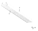
- Figuren 17 bis 19
- Skizzen zu einem sechsten Ausführungsbeispiel.
- In
Fig. 1 ist ein erstes Ausführungsbeispiel eines erfindungsgemäßen Rasterelements gezeigt. Das Rasterelement ist für eine Leuchte vorgesehen. Bei der Leuchte kann es sich beispielsweise um eine Decken- oder Pendelleuchte handeln. Mit dem Rasterelement soll dabei in an sich bekannter Weise eine Blendung, die möglicherweise durch die Leuchte hervorgerufen werden könnte, verhindert oder verringert werden. - Das Rasterelement weist Querlamellen 2 auf. Die Querlamellen 2 können eine verhältnismäßig niedrige Höhe aufweisen. Beispielsweise kann vorgesehen sein, dass die Höhe der Querlamellen weniger als 20 mm, vorzugsweise weniger als 15 mm, besonders bevorzugt weniger als 5 mm beträgt. Beispielsweise kann die Höhe zwischen 3 mm und 4,5 mm betragen. Die Höhe kann insbesondere mehr als 2 mm betragen.
- Das Rasterelement umfasst ein erstes Querlamellen-Modul 4 und ein zweites Querlamellen-Modul 6. Dabei ist das erste Querlamellen-Modul 4 insgesamt einstückig ausgebildet und weist mehrere Querlamellen 2 auf. Beispielsweise kann vorgesehen sein, dass das erste Querlamellen-Modul 4 zwischen fünf und einhundertundzwanzig oder zwischen fünf und vierzig, vorzugsweise zwischen acht und zweiunddreißig Querlamellen 2 aufweist. Es wären insbesondere auch Ausführungsformen mit 68 oder 72 Querlamellen denkbar.
- Das Querlamellen-Modul 4 kann aus Kunststoff bestehen. Herstellungstechnisch vorteilhaft kann es beispielsweise mit Hilfe eines Spritzgussverfahrens hergestellt sein.
- Das erste Querlamellen-Modul 4 kann zwei Längsbereiche 21, 22 aufweisen, die jeweils Enden der Querlamellen 2 miteinander verbinden.
- Das zweite Querlamellen-Modul 6 kann baugleich mit dem ersten Querlamellen-Modul 4 ausgeführt sein. Das zweite Querlamellen-Modul 6 kann dementsprechend ebenfalls zwei Längsbereiche 23, 24 aufweisen.
- Das erste Querlamellen-Modul 4 ist mit dem zweiten Querlamellen-Modul 6 mechanisch verbunden. Hierzu können jeweils zwei aneinander grenzende Endbereiche der Längsbereiche 21, 23 bzw. 22, 24 miteinander verbunden sein, so dass zwei Verbindungsstellen 31, 32 gebildet sind.
- Die Verbindung zwischen den beiden Querlamellen-Modulen 4, 6 ist vorzugsweise eine Formschluss-Verbindung. Beispielsweise können hierzu an den Längsbereichen Verbindungselemente in Form von Stiften und entsprechenden Öffnungen ausgebildet sein, in welche die Stifte zur Herstellung der Formschluss-Verbindung eingreifen.
- Es kann vorgesehen sein, dass das Rasterelement insgesamt mehr als zwei Querlamellen-Module umfasst. Dies ist insbesondere im Fall eines Rasterelements vorteilhaft, bei dem das Verhältnis von Länge zu Breite besonders groß ist, also beispielswiese größer als vier, insbesondere größer als zehn. In diesem Fall ist es vorteilhaft, wenn die Verbindungselemente derart ausgebildet sind, dass sich die Querlamellen-Module kettenartig zu einem langen Gebilde zusammensetzen lassen.
- In der vorliegenden Beschreibung sind bei den unterschiedlichen Ausführungsformen bzw. Varianten entsprechende Teile jeweils mit demselben Bezugszeichen versehen.
- In
Fig. 2 ist beispielhaft eine Variante dargestellt, bei der die Formschlussverbindung zwischen den Querlamellen-Modulen 4, 6 mittels alternativer Verbindungselemente ausgebildet ist. Die Querlamellen-Module 4, 6 sind dabei derart ausgestaltet, dass sie durch entsprechende Ausnehmungen und darin eingreifende Vorsprünge zusammengefügt werden können. - In den
Figuren 3 bis 6 ist ein zweites Ausführungsbeispiel dargestellt. Bei diesem Beispiel weisen die Längsbereiche 21, 22, 23, 24 - mit Bezug auf die Ebene der Querlamellen 2 - jeweils geneigte Seitenwände 40 auf. Hierdurch wird eine erhöhte Stabilität der Verbindung zwischen den Querlamellen-Modulen 4, 6 und damit eine erhöhte Stabilität des Rasterelements insgesamt ermöglicht. Außerdem kann die Neigung der Seitenwände 40 einen sichtbaren Bund oder eine Designblende bilden. - Weiterhin kann an den Seitenwänden 40 jeweils ein beispielsweise blattförmiger Vorsprung 41 vorgesehen sein, auf welchen ein Seitenteil 8 im Sinn einer Formschlussverbindung aufgefädelt werden kann, wie in der Querschnitt-Darstellung der
Fig. 6 gezeigt. Das Seitenteil 8 kann beispielsweise aus Blech geformt sein. Es können dabei insgesamt zwei Seitenteile 8 vorgesehen sein, die längs zu beiden Seiten der Querlamellen 2 verlaufend angeordnet sind und die sich dabei vorzugsweise über die gesamte Länge des Rasterelements erstrecken. Das Seitenteil 8 kann insbesondere zur Stabilisierung der Verbindung zwischen den Querlamellen-Modulen 4, 6 dienen. - Das Seitenteil 8 kann einstückig ausgebildet sein.
- Funktionell vorteilhaft kann weiterhin vorgesehen sein, dass das Seitenteil 8 eine reflektierende Seitenwand des Rasterelements, also einen Seitenreflektor des Rasterelements bildet. Die reflektierende Seitenwand kann dabei - wie in
Fig. 6 prinzipiell dargestellt - mit Bezug auf die Querlamellen 2 nach innen, also zur Mitte der Querlamellen 2 hin, geneigt sein. - Die Seitenwand 8 kann dabei weiterhin so ausgestaltet sein, dass ihre Höhe H mit Bezug auf die Ebene E, die durch die Oberkanten der Querlamellen 2 festgelegt ist, mehr als das Zehnfache der Höhe h der Querlamellen 2 beträgt. Dies ermöglicht eine besonders wirkungsvolle Seitenreflexion, die vorteilhaft für die optischen Eigenschaften des Rasterelements ist.
- In den
Figuren 7 bis 9 sind Skizzen zu einem dritten Ausführungsbeispiel gezeigt. Soweit nicht anders angegeben gelten die obigen Ausführungen auch für dieses Ausführungsbeispiel und die weiteren Ausführungsbeispiele bzw. Varianten entsprechend. - Bei diesem Beispiel können die Querlamellen-Module 4, 6 stumpf aneinandergelegt vorgesehen sein. Sie müssen also hierbei nicht unmittelbar verbunden sein. Zum Verbinden und Stabilisieren kann wiederum wenigstens ein Seitenteil 8, beispielsweise in Form eines Blechteils vorgesehen sein.
- Zur Verbindung des Seitenteils 8 mit dem ersten Querlamellen-Modul 4 kann das Seitenteil 8 ein Loch 50 aufweisen, wobei ein an dem ersten Querlamellen-Modul 4 ausgebildeter Stift 51 in das Loch 50 eingreift. Zur weitergehenden Unterstützung bzw. Stabilisierung dieser Verbindung kann das Seitenteil 8 weiterhin einen Bereich 53 aufweisen, der den Stift 51 in das Loch 50 drückt.
- Der Stift 51 kann beispielsweise an dem Längsbereich 21 des ersten Querlamellen-Moduls 4 ausgebildet sein. Wie aus
Fig. 9 beispielhaft hervorgeht, kann der Bereich 53 durch eine entsprechende Biegung des Seitenteils 8 gebildet sein. - Es können zur weitergehenden Stabilisierung der Verbindung bzw. Zentrierung der Querlamellen-Module 4, 6 mehrere entsprechende Löcher 50 in Form eines Bohrungsmusters und dementsprechend mehrere Stifte 51 vorgesehen sein, die an dem ersten Querlamellen-Modul 4 und/oder an dem zweiten Querlamellen-Modul 6 ausgebildet sind.
- Wiederum kann das Seitenteil 8 eine reflektierende Wand aufweisen, so dass es nicht nur der Stabilisierung, sondern auch als Seitenreflektor dient.
- Für die Größenverhältnisse gelten insbesondere die obigen Ausführungen mit Bezug auf
Fig. 6 analog. - Natürlich können wiederum zwei entsprechende Seitenteile 8 vorgesehen sein.
- In den
Figuren 10 bis 13 sind Skizzen zu einem vierten Ausführungsbeispiel gezeigt. Auch hier gelten die obigen Ausführungen wiederum entsprechend. Das Seitenteil 8 bzw. die Seitenteile 8 können also entsprechend den obigen Beschreibungen geformt und ausgebildet sein. Die Verbindung der Querlamellen-Module 4, 6 kann wiederum über wenigstens einen Stift 51 vorgesehen sein, der in wenigstens ein an dem Seitenteil 8 ausgebildetes Loch 50 eingreift. Durch einen gegenüberliegenden Vorsprung 53 kann wiederum eine Fixierung des Querlamellen-Moduls 4 bzw. der Querlamellen-Module 4, 6 erzielt werden. - In
Fig. 12 ist weiterhin ein Teil einer transparenten Abdeckung 60 einer Leuchte skizziert, in der das Rasterelement angeordnet ist. - In den
Figuren 14 bis 16 sind Skizzen zu einem fünften Ausführungsbeispiel gezeigt, wobei die obigen Ausführungen wiederum analog gelten, soweit nicht anders angegeben. Das Seitenteil 8 kann nunmehr allerdings zwei Stücke umfassen, also beispielsweise zweiteilig ausgebildet sein, wobei das Loch 50 in dem ersten Stück bzw. Teil 8.1 angeordnet ist und wobei das zweite Stück bzw. Teil 8.2 den Bereich 53 bildet, durch den ein Druck auf das Querlamellen-Modul 4 ausgeübt wird, so dass hierdurch der Stift 51 in dem Loch 50 gehalten und dadurch die Verbindung stabilisiert wird. - In den
Figuren 17 und 18 sind Skizzen zu einem sechsten Ausführungsbeispiel gezeigt, wobei die obigen Ausführungen wiederum analog gelten, soweit nicht anders angegeben. Ferner werden für gleiche Teile gleiche Bezugszeichen verwendet. Die Besonderheit dieses sechsten Ausführungsbeispiels besteht darin, dass alternierend zu den Stiften 51, die wiederum in Löcher 50 des Seitenteils 8 eingreifen, Schnapphaken 70 an dem Längsbereich 21 des Querlamellen-Moduls 4 vorgesehen sind, welche mit dem Seitenteil 8 zusammenwirken. Das Seitenteil weist hierzu entsprechende Einkerbungen 71 auf, in welche die Schnapphaken 70 einrasten. Durch das Zusammenwirken der Schnapphaken 70 mit dem Seitenteil 8 wird dieses automatisch leicht nach unten gezogen, also die Stifte 51 in die Öffnungen 50 gedrückt, so dass im Vergleich zu den vorherigen Varianten ggf. auf den Bereich 53 verzichtet werden kann. Die Nutzung der Schnapphaken wäre selbstverständlich auch bei den vorherigen Ausführungsbeispielen möglich. - Allen dargestellten Ausführungsbeispielen bzw. Varianten ist gemein, dass die Seitenteile 8 nicht nur eine Stabilisierung der Anordnung bewirken sondern gleichzeitig auch als Seitenreflektoren dienen können. Es ergibt sich dann insgesamt eine Rasteranordnung, wie sie in
Figur 19 dargestellt ist.
Claims (14)
- Rasterelement für eine Leuchte,
aufweisend Querlamellen (2),
gekennzeichnet durch- ein erstes Querlamellen-Modul (4) und- ein zweites Querlamellen-Modul (6),wobei das erste Querlamellen-Modul (4) und das zweite Querlamellen-Modul (6) jeweils einstückig ausgebildet sind und jeweils mehrere Querlamellen aufweisen und wobei das erste Querlamellen-Modul (4) mit dem zweiten Querlamellen-Modul (6) mechanisch verbunden ist. - Rasterelement nach Anspruch 1,
bei dem das erste Querlamellen-Modul (4) mit dem zweiten Querlamellen-Modul (6) formschlüssig verbunden ist. - Rasterelement nach Anspruch 1 oder 2,
bei dem das erste Querlamellen-Modul (4) zwischen fünf und einhundertundzwanzig, beispielsweise achtundsechzig oder zweiundsiebzig, insbesondere zwischen fünf und vierzig, vorzugsweise zwischen acht und zweiunddreißig Querlamellen aufweist. - Rasterelement nach einem der vorhergehenden Ansprüche,
bei dem das erste Querlamellen-Modul (4) und das zweite Querlamellen-Modul (6) baugleich sind. - Rasterelement nach einem der vorhergehenden Ansprüche,
weiterhin aufweisend- ein Seitenteil (8), das mit dem ersten Querlamellen-Modul (4) und/oder mit dem zweiten Querlamellen-Modul (6) mechanisch verbunden ist. - Rasterelement nach Anspruch 5,
bei dem das Seitenteil (8) mit dem ersten Querlamellen-Modul (4) und/oder mit dem zweiten Querlamellen-Modul (6) formschlüssig, beispielsweise mittels einer Rastverbindung verbunden ist. - Rasterelement nach Anspruch 5 oder 6,
bei dem das Seitenteil (8) einen Seitenreflektor bildet. - Rasterelement nach einem der Ansprüche 5 bis 7,
bei dem das Seitenteil (8) aus Blech gefertigt ist. - Rasterelement nach einem der Ansprüche 5 bis 8,
bei dem das Seitenteil (8) ein Loch (10) aufweist und das erste Querlamellen-Modul (4) einen in das Loch (10) eingreifenden Stift (12) aufweist. - Rasterelement nach Anspruch 9,
bei dem das Seitenteil (8) einen Bereich (53) aufweist, der den Stift (12) in das Loch (10) drückt, so dass hierdurch die Verbindung zwischen dem ersten Querlamellen-Modul (4) und dem Seitenteil (8) stabilisiert ist. - Rasterelement nach Anspruch 10,
bei dem das Seitenteil (8) zwei Stücke umfasst, wobei das Loch (10) in dem ersten Stück (8.1) angeordnet ist und der Bereich (53) in dem zweiten Stück (8.2). - Rasterelement nach einem der Ansprüche 9 bis 11,
bei dem das Seitenteil (8) zusätzlich eine Ausnehmung (71) aufweist und das erste Querlamellen-Modul (4) einen die Ausnehmung (71) hintergreifenden Schnapphaken (70) aufweist. - Rasterelement nach Anspruch 12,
bei dem das Seitenteil (8) alternierend mehrere Löcher (10) und Ausnehmungen (71) aufweist. - Rasterelement nach einem der vorhergehenden Ansprüche,
bei dem das erste Querlamellen-Modul (4) und das zweite Querlamellen-Modul (6) aus Kunststoff gefertigt sind, beispielsweise mit Hilfe eines Spritzgussverfahrens.
Applications Claiming Priority (1)
| Application Number | Priority Date | Filing Date | Title |
|---|---|---|---|
| DE200920006399 DE202009006399U1 (de) | 2009-04-30 | 2009-04-30 | Rasterelement für eine Leuchte |
Publications (2)
| Publication Number | Publication Date |
|---|---|
| EP2251591A1 true EP2251591A1 (de) | 2010-11-17 |
| EP2251591B1 EP2251591B1 (de) | 2014-09-10 |
Family
ID=42536727
Family Applications (1)
| Application Number | Title | Priority Date | Filing Date |
|---|---|---|---|
| EP20100159469 Active EP2251591B1 (de) | 2009-04-30 | 2010-04-09 | Rasterelement für eine Leuchte |
Country Status (2)
| Country | Link |
|---|---|
| EP (1) | EP2251591B1 (de) |
| DE (1) | DE202009006399U1 (de) |
Citations (6)
| Publication number | Priority date | Publication date | Assignee | Title |
|---|---|---|---|---|
| GB802205A (en) | 1954-10-28 | 1958-10-01 | Bertram A Wilson | Improvements relating to suspension means for light diffusing devices, particularly for use in connection with fluorescent lighting |
| US3033979A (en) | 1957-09-13 | 1962-05-08 | Curtiss Electro Lighting Inc | Overlapping and interlocking louvers for light fixtures |
| US3544787A (en) * | 1968-06-24 | 1970-12-01 | Integrated Lighting Ltd | Louver construction |
| EP0795719A1 (de) * | 1996-03-14 | 1997-09-17 | Siemens Aktiengesellschaft | Modular aufgebaute Leuchteneinheit |
| FR2762630A1 (fr) * | 1997-04-29 | 1998-10-30 | Decoral | Grille pour la construction d'un faux plafond suspendu |
| DE102006017043A1 (de) * | 2006-04-11 | 2007-10-18 | Siteco Beleuchtungstechnik Gmbh | Verbindungstechnik von Lamellen in Leuchtenrastern |
Family Cites Families (5)
| Publication number | Priority date | Publication date | Assignee | Title |
|---|---|---|---|---|
| US4407011A (en) * | 1980-12-08 | 1983-09-27 | Donn Incorporated | Integrated lighting systems for suspended ceilings or the like |
| DE9016295U1 (de) * | 1990-11-30 | 1992-04-02 | Licentia Patent-Verwaltungs-Gmbh, 6000 Frankfurt, De | |
| FR2712068A1 (fr) * | 1993-11-03 | 1995-05-12 | Philips Eclairage | Luminaire comportant une enveloppe et une grille de fermeture. |
| DE10216761B4 (de) * | 2002-04-02 | 2007-07-19 | Siteco Beleuchtungstechnik Gmbh | Leuchte mit reibschlüssig befestigtem Leuchtenbauteil und zugehöriges Leuchtenbauteil |
| DE10221630A1 (de) * | 2002-05-15 | 2003-11-27 | Zumtobel Staff Gmbh | Leuchtenraster mit doppelwandigen Seitenreflektoren |
-
2009
- 2009-04-30 DE DE200920006399 patent/DE202009006399U1/de not_active Expired - Lifetime
-
2010
- 2010-04-09 EP EP20100159469 patent/EP2251591B1/de active Active
Patent Citations (6)
| Publication number | Priority date | Publication date | Assignee | Title |
|---|---|---|---|---|
| GB802205A (en) | 1954-10-28 | 1958-10-01 | Bertram A Wilson | Improvements relating to suspension means for light diffusing devices, particularly for use in connection with fluorescent lighting |
| US3033979A (en) | 1957-09-13 | 1962-05-08 | Curtiss Electro Lighting Inc | Overlapping and interlocking louvers for light fixtures |
| US3544787A (en) * | 1968-06-24 | 1970-12-01 | Integrated Lighting Ltd | Louver construction |
| EP0795719A1 (de) * | 1996-03-14 | 1997-09-17 | Siemens Aktiengesellschaft | Modular aufgebaute Leuchteneinheit |
| FR2762630A1 (fr) * | 1997-04-29 | 1998-10-30 | Decoral | Grille pour la construction d'un faux plafond suspendu |
| DE102006017043A1 (de) * | 2006-04-11 | 2007-10-18 | Siteco Beleuchtungstechnik Gmbh | Verbindungstechnik von Lamellen in Leuchtenrastern |
Also Published As
| Publication number | Publication date |
|---|---|
| EP2251591B1 (de) | 2014-09-10 |
| DE202009006399U1 (de) | 2010-09-16 |
Similar Documents
| Publication | Publication Date | Title |
|---|---|---|
| WO2010081532A1 (de) | Paneel, insbesondere fussbodenpaneel | |
| EP3009035B1 (de) | Knotenverbindung für verbindungsholme und zugehöriges modular aufgebautes tischgestell | |
| DE102010060742A1 (de) | Form zur Herstellung von Betonformsteinen | |
| DE102016124078B3 (de) | Verbindungsanordnung für die Verbindung von zwei Schaltschrankrahmengestellen | |
| EP2991170A1 (de) | Anordnung mit Modulteilen und einstellbaren Kodiermitteln | |
| DE2507721C3 (de) | Selbsttragende Mosaikschaltwand | |
| EP2251591B1 (de) | Rasterelement für eine Leuchte | |
| EP0795719B1 (de) | Modular aufgebaute Leuchteneinheit | |
| DE102016015791B4 (de) | Verbindungsanordnung für die Verbindung von zwei Schaltschrankrahmengestellen | |
| EP3608588B1 (de) | Haltefeder für leuchte | |
| DE3239692A1 (de) | Leuchtenraster | |
| DE102016220022A1 (de) | Kombination eines Steckers mit einem Deckel | |
| EP2283748A1 (de) | Trägersystem | |
| DE3902008C2 (de) | ||
| AT515601A2 (de) | System zur Aufnahme von Lichtmodulen sowie Verfahren für dessen Herstellung | |
| EP3669704B1 (de) | Trägersystem | |
| EP2620936A2 (de) | Rahmenelement für eine Leuchte | |
| DE10221630A1 (de) | Leuchtenraster mit doppelwandigen Seitenreflektoren | |
| EP0528198B1 (de) | Lamelle zur Befestigung eines Domes an einem Lamellenraster einer Leuchte | |
| AT513711B1 (de) | Reflektor für eine Leuchte, insbesondere für eine Deckeneinbauleuchte | |
| EP1256758B1 (de) | Leuchtengehäuse | |
| DE102008055686A1 (de) | Montageschiene | |
| DE2916331A1 (de) | Verfahren zur herstellung eines rasters, insbesondere eines leuchtenblendschutzrasters fuer spiegelrasterleuchten | |
| EP1944419A1 (de) | Abdeckung für eine Entwässerungsrinne | |
| EP3067495A1 (de) | Haltelement eines beschlagteils eines treibstangenbeschlages |
Legal Events
| Date | Code | Title | Description |
|---|---|---|---|
| PUAI | Public reference made under article 153(3) epc to a published international application that has entered the european phase |
Free format text: ORIGINAL CODE: 0009012 |
|
| AK | Designated contracting states |
Kind code of ref document: A1 Designated state(s): AT BE BG CH CY CZ DE DK EE ES FI FR GB GR HR HU IE IS IT LI LT LU LV MC MK MT NL NO PL PT RO SE SI SK SM TR |
|
| AX | Request for extension of the european patent |
Extension state: AL BA ME RS |
|
| 17P | Request for examination filed |
Effective date: 20110517 |
|
| GRAP | Despatch of communication of intention to grant a patent |
Free format text: ORIGINAL CODE: EPIDOSNIGR1 |
|
| RIC1 | Information provided on ipc code assigned before grant |
Ipc: F21V 11/02 20060101AFI20140314BHEP Ipc: E04B 9/36 20060101ALI20140314BHEP Ipc: F21V 11/06 20060101ALI20140314BHEP Ipc: F21V 17/00 20060101ALN20140314BHEP |
|
| INTG | Intention to grant announced |
Effective date: 20140422 |
|
| GRAS | Grant fee paid |
Free format text: ORIGINAL CODE: EPIDOSNIGR3 |
|
| GRAA | (expected) grant |
Free format text: ORIGINAL CODE: 0009210 |
|
| AK | Designated contracting states |
Kind code of ref document: B1 Designated state(s): AT BE BG CH CY CZ DE DK EE ES FI FR GB GR HR HU IE IS IT LI LT LU LV MC MK MT NL NO PL PT RO SE SI SK SM TR |
|
| REG | Reference to a national code |
Ref country code: GB Ref legal event code: FG4D Free format text: NOT ENGLISH |
|
| REG | Reference to a national code |
Ref country code: CH Ref legal event code: EP Ref country code: CH Ref legal event code: NV Representative=s name: FIAMMENGHI-FIAMMENGHI, CH |
|
| REG | Reference to a national code |
Ref country code: IE Ref legal event code: FG4D Free format text: LANGUAGE OF EP DOCUMENT: GERMAN |
|
| REG | Reference to a national code |
Ref country code: AT Ref legal event code: REF Ref document number: 686880 Country of ref document: AT Kind code of ref document: T Effective date: 20141015 |
|
| REG | Reference to a national code |
Ref country code: DE Ref legal event code: R096 Ref document number: 502010007840 Country of ref document: DE Effective date: 20141023 |
|
| PG25 | Lapsed in a contracting state [announced via postgrant information from national office to epo] |
Ref country code: LT Free format text: LAPSE BECAUSE OF FAILURE TO SUBMIT A TRANSLATION OF THE DESCRIPTION OR TO PAY THE FEE WITHIN THE PRESCRIBED TIME-LIMIT Effective date: 20140910 Ref country code: FI Free format text: LAPSE BECAUSE OF FAILURE TO SUBMIT A TRANSLATION OF THE DESCRIPTION OR TO PAY THE FEE WITHIN THE PRESCRIBED TIME-LIMIT Effective date: 20140910 Ref country code: NO Free format text: LAPSE BECAUSE OF FAILURE TO SUBMIT A TRANSLATION OF THE DESCRIPTION OR TO PAY THE FEE WITHIN THE PRESCRIBED TIME-LIMIT Effective date: 20141210 Ref country code: SE Free format text: LAPSE BECAUSE OF FAILURE TO SUBMIT A TRANSLATION OF THE DESCRIPTION OR TO PAY THE FEE WITHIN THE PRESCRIBED TIME-LIMIT Effective date: 20140910 Ref country code: GR Free format text: LAPSE BECAUSE OF FAILURE TO SUBMIT A TRANSLATION OF THE DESCRIPTION OR TO PAY THE FEE WITHIN THE PRESCRIBED TIME-LIMIT Effective date: 20141211 Ref country code: ES Free format text: LAPSE BECAUSE OF FAILURE TO SUBMIT A TRANSLATION OF THE DESCRIPTION OR TO PAY THE FEE WITHIN THE PRESCRIBED TIME-LIMIT Effective date: 20140910 |
|
| REG | Reference to a national code |
Ref country code: NL Ref legal event code: VDEP Effective date: 20140910 |
|
| REG | Reference to a national code |
Ref country code: LT Ref legal event code: MG4D |
|
| PG25 | Lapsed in a contracting state [announced via postgrant information from national office to epo] |
Ref country code: CY Free format text: LAPSE BECAUSE OF FAILURE TO SUBMIT A TRANSLATION OF THE DESCRIPTION OR TO PAY THE FEE WITHIN THE PRESCRIBED TIME-LIMIT Effective date: 20140910 Ref country code: LV Free format text: LAPSE BECAUSE OF FAILURE TO SUBMIT A TRANSLATION OF THE DESCRIPTION OR TO PAY THE FEE WITHIN THE PRESCRIBED TIME-LIMIT Effective date: 20140910 Ref country code: HR Free format text: LAPSE BECAUSE OF FAILURE TO SUBMIT A TRANSLATION OF THE DESCRIPTION OR TO PAY THE FEE WITHIN THE PRESCRIBED TIME-LIMIT Effective date: 20140910 |
|
| PG25 | Lapsed in a contracting state [announced via postgrant information from national office to epo] |
Ref country code: NL Free format text: LAPSE BECAUSE OF FAILURE TO SUBMIT A TRANSLATION OF THE DESCRIPTION OR TO PAY THE FEE WITHIN THE PRESCRIBED TIME-LIMIT Effective date: 20140910 |
|
| PG25 | Lapsed in a contracting state [announced via postgrant information from national office to epo] |
Ref country code: EE Free format text: LAPSE BECAUSE OF FAILURE TO SUBMIT A TRANSLATION OF THE DESCRIPTION OR TO PAY THE FEE WITHIN THE PRESCRIBED TIME-LIMIT Effective date: 20140910 Ref country code: RO Free format text: LAPSE BECAUSE OF FAILURE TO SUBMIT A TRANSLATION OF THE DESCRIPTION OR TO PAY THE FEE WITHIN THE PRESCRIBED TIME-LIMIT Effective date: 20140910 Ref country code: PT Free format text: LAPSE BECAUSE OF FAILURE TO SUBMIT A TRANSLATION OF THE DESCRIPTION OR TO PAY THE FEE WITHIN THE PRESCRIBED TIME-LIMIT Effective date: 20150112 Ref country code: CZ Free format text: LAPSE BECAUSE OF FAILURE TO SUBMIT A TRANSLATION OF THE DESCRIPTION OR TO PAY THE FEE WITHIN THE PRESCRIBED TIME-LIMIT Effective date: 20140910 Ref country code: IS Free format text: LAPSE BECAUSE OF FAILURE TO SUBMIT A TRANSLATION OF THE DESCRIPTION OR TO PAY THE FEE WITHIN THE PRESCRIBED TIME-LIMIT Effective date: 20150110 Ref country code: SK Free format text: LAPSE BECAUSE OF FAILURE TO SUBMIT A TRANSLATION OF THE DESCRIPTION OR TO PAY THE FEE WITHIN THE PRESCRIBED TIME-LIMIT Effective date: 20140910 |
|
| PG25 | Lapsed in a contracting state [announced via postgrant information from national office to epo] |
Ref country code: PL Free format text: LAPSE BECAUSE OF FAILURE TO SUBMIT A TRANSLATION OF THE DESCRIPTION OR TO PAY THE FEE WITHIN THE PRESCRIBED TIME-LIMIT Effective date: 20140910 |
|
| REG | Reference to a national code |
Ref country code: DE Ref legal event code: R097 Ref document number: 502010007840 Country of ref document: DE |
|
| PLBE | No opposition filed within time limit |
Free format text: ORIGINAL CODE: 0009261 |
|
| STAA | Information on the status of an ep patent application or granted ep patent |
Free format text: STATUS: NO OPPOSITION FILED WITHIN TIME LIMIT |
|
| PG25 | Lapsed in a contracting state [announced via postgrant information from national office to epo] |
Ref country code: DK Free format text: LAPSE BECAUSE OF FAILURE TO SUBMIT A TRANSLATION OF THE DESCRIPTION OR TO PAY THE FEE WITHIN THE PRESCRIBED TIME-LIMIT Effective date: 20140910 |
|
| 26N | No opposition filed |
Effective date: 20150611 |
|
| PG25 | Lapsed in a contracting state [announced via postgrant information from national office to epo] |
Ref country code: IT Free format text: LAPSE BECAUSE OF FAILURE TO SUBMIT A TRANSLATION OF THE DESCRIPTION OR TO PAY THE FEE WITHIN THE PRESCRIBED TIME-LIMIT Effective date: 20140910 |
|
| PG25 | Lapsed in a contracting state [announced via postgrant information from national office to epo] |
Ref country code: SI Free format text: LAPSE BECAUSE OF FAILURE TO SUBMIT A TRANSLATION OF THE DESCRIPTION OR TO PAY THE FEE WITHIN THE PRESCRIBED TIME-LIMIT Effective date: 20140910 Ref country code: LU Free format text: LAPSE BECAUSE OF FAILURE TO SUBMIT A TRANSLATION OF THE DESCRIPTION OR TO PAY THE FEE WITHIN THE PRESCRIBED TIME-LIMIT Effective date: 20150409 Ref country code: MC Free format text: LAPSE BECAUSE OF FAILURE TO SUBMIT A TRANSLATION OF THE DESCRIPTION OR TO PAY THE FEE WITHIN THE PRESCRIBED TIME-LIMIT Effective date: 20140910 |
|
| REG | Reference to a national code |
Ref country code: IE Ref legal event code: MM4A |
|
| REG | Reference to a national code |
Ref country code: FR Ref legal event code: PLFP Year of fee payment: 7 |
|
| PG25 | Lapsed in a contracting state [announced via postgrant information from national office to epo] |
Ref country code: IE Free format text: LAPSE BECAUSE OF NON-PAYMENT OF DUE FEES Effective date: 20150409 |
|
| PG25 | Lapsed in a contracting state [announced via postgrant information from national office to epo] |
Ref country code: MT Free format text: LAPSE BECAUSE OF FAILURE TO SUBMIT A TRANSLATION OF THE DESCRIPTION OR TO PAY THE FEE WITHIN THE PRESCRIBED TIME-LIMIT Effective date: 20140910 |
|
| REG | Reference to a national code |
Ref country code: FR Ref legal event code: PLFP Year of fee payment: 8 |
|
| PG25 | Lapsed in a contracting state [announced via postgrant information from national office to epo] |
Ref country code: BG Free format text: LAPSE BECAUSE OF FAILURE TO SUBMIT A TRANSLATION OF THE DESCRIPTION OR TO PAY THE FEE WITHIN THE PRESCRIBED TIME-LIMIT Effective date: 20140910 Ref country code: SM Free format text: LAPSE BECAUSE OF FAILURE TO SUBMIT A TRANSLATION OF THE DESCRIPTION OR TO PAY THE FEE WITHIN THE PRESCRIBED TIME-LIMIT Effective date: 20140910 Ref country code: HU Free format text: LAPSE BECAUSE OF FAILURE TO SUBMIT A TRANSLATION OF THE DESCRIPTION OR TO PAY THE FEE WITHIN THE PRESCRIBED TIME-LIMIT; INVALID AB INITIO Effective date: 20100409 |
|
| PG25 | Lapsed in a contracting state [announced via postgrant information from national office to epo] |
Ref country code: BE Free format text: LAPSE BECAUSE OF NON-PAYMENT OF DUE FEES Effective date: 20150430 |
|
| PG25 | Lapsed in a contracting state [announced via postgrant information from national office to epo] |
Ref country code: TR Free format text: LAPSE BECAUSE OF FAILURE TO SUBMIT A TRANSLATION OF THE DESCRIPTION OR TO PAY THE FEE WITHIN THE PRESCRIBED TIME-LIMIT Effective date: 20140910 |
|
| REG | Reference to a national code |
Ref country code: FR Ref legal event code: PLFP Year of fee payment: 9 |
|
| PG25 | Lapsed in a contracting state [announced via postgrant information from national office to epo] |
Ref country code: MK Free format text: LAPSE BECAUSE OF FAILURE TO SUBMIT A TRANSLATION OF THE DESCRIPTION OR TO PAY THE FEE WITHIN THE PRESCRIBED TIME-LIMIT Effective date: 20140910 |
|
| PGFP | Annual fee paid to national office [announced via postgrant information from national office to epo] |
Ref country code: AT Payment date: 20180426 Year of fee payment: 9 |
|
| PGFP | Annual fee paid to national office [announced via postgrant information from national office to epo] |
Ref country code: FR Payment date: 20190426 Year of fee payment: 10 |
|
| PGFP | Annual fee paid to national office [announced via postgrant information from national office to epo] |
Ref country code: CH Payment date: 20190426 Year of fee payment: 10 |
|
| REG | Reference to a national code |
Ref country code: AT Ref legal event code: MM01 Ref document number: 686880 Country of ref document: AT Kind code of ref document: T Effective date: 20190409 |
|
| REG | Reference to a national code |
Ref country code: DE Ref legal event code: R084 Ref document number: 502010007840 Country of ref document: DE |
|
| PG25 | Lapsed in a contracting state [announced via postgrant information from national office to epo] |
Ref country code: AT Free format text: LAPSE BECAUSE OF NON-PAYMENT OF DUE FEES Effective date: 20190409 |
|
| REG | Reference to a national code |
Ref country code: CH Ref legal event code: PL |
|
| PG25 | Lapsed in a contracting state [announced via postgrant information from national office to epo] |
Ref country code: LI Free format text: LAPSE BECAUSE OF NON-PAYMENT OF DUE FEES Effective date: 20200430 Ref country code: FR Free format text: LAPSE BECAUSE OF NON-PAYMENT OF DUE FEES Effective date: 20200430 Ref country code: CH Free format text: LAPSE BECAUSE OF NON-PAYMENT OF DUE FEES Effective date: 20200430 |
|
| PGFP | Annual fee paid to national office [announced via postgrant information from national office to epo] |
Ref country code: GB Payment date: 20220419 Year of fee payment: 13 |
|
| P01 | Opt-out of the competence of the unified patent court (upc) registered |
Effective date: 20230530 |
|
| PGFP | Annual fee paid to national office [announced via postgrant information from national office to epo] |
Ref country code: DE Payment date: 20230427 Year of fee payment: 14 |
|
| GBPC | Gb: european patent ceased through non-payment of renewal fee |
Effective date: 20230409 |
|
| PG25 | Lapsed in a contracting state [announced via postgrant information from national office to epo] |
Ref country code: GB Free format text: LAPSE BECAUSE OF NON-PAYMENT OF DUE FEES Effective date: 20230409 |
|
| PG25 | Lapsed in a contracting state [announced via postgrant information from national office to epo] |
Ref country code: GB Free format text: LAPSE BECAUSE OF NON-PAYMENT OF DUE FEES Effective date: 20230409 |