EP2247094A1 - Orthophotografisches bilderzeugungsverfahren und abbildungseinrichtung - Google Patents
Orthophotografisches bilderzeugungsverfahren und abbildungseinrichtung Download PDFInfo
- Publication number
- EP2247094A1 EP2247094A1 EP09703910A EP09703910A EP2247094A1 EP 2247094 A1 EP2247094 A1 EP 2247094A1 EP 09703910 A EP09703910 A EP 09703910A EP 09703910 A EP09703910 A EP 09703910A EP 2247094 A1 EP2247094 A1 EP 2247094A1
- Authority
- EP
- European Patent Office
- Prior art keywords
- image
- camera
- capturing
- obliquely
- nadir
- Prior art date
- Legal status (The legal status is an assumption and is not a legal conclusion. Google has not performed a legal analysis and makes no representation as to the accuracy of the status listed.)
- Granted
Links
Images


Classifications
-
- G—PHYSICS
- G06—COMPUTING OR CALCULATING; COUNTING
- G06T—IMAGE DATA PROCESSING OR GENERATION, IN GENERAL
- G06T3/00—Geometric image transformations in the plane of the image
- G06T3/14—Transformations for image registration, e.g. adjusting or mapping for alignment of images
- G06T3/153—Transformations for image registration, e.g. adjusting or mapping for alignment of images using elastic snapping
-
- G—PHYSICS
- G01—MEASURING; TESTING
- G01C—MEASURING DISTANCES, LEVELS OR BEARINGS; SURVEYING; NAVIGATION; GYROSCOPIC INSTRUMENTS; PHOTOGRAMMETRY OR VIDEOGRAMMETRY
- G01C11/00—Photogrammetry or videogrammetry, e.g. stereogrammetry; Photographic surveying
- G01C11/02—Picture taking arrangements specially adapted for photogrammetry or photographic surveying, e.g. controlling overlapping of pictures
-
- G—PHYSICS
- G06—COMPUTING OR CALCULATING; COUNTING
- G06T—IMAGE DATA PROCESSING OR GENERATION, IN GENERAL
- G06T3/00—Geometric image transformations in the plane of the image
- G06T3/06—Topological mapping of higher dimensional structures onto lower dimensional surfaces
-
- H—ELECTRICITY
- H04—ELECTRIC COMMUNICATION TECHNIQUE
- H04N—PICTORIAL COMMUNICATION, e.g. TELEVISION
- H04N23/00—Cameras or camera modules comprising electronic image sensors; Control thereof
- H04N23/60—Control of cameras or camera modules
- H04N23/698—Control of cameras or camera modules for achieving an enlarged field of view, e.g. panoramic image capture
-
- H—ELECTRICITY
- H04—ELECTRIC COMMUNICATION TECHNIQUE
- H04N—PICTORIAL COMMUNICATION, e.g. TELEVISION
- H04N23/00—Cameras or camera modules comprising electronic image sensors; Control thereof
- H04N23/90—Arrangement of cameras or camera modules, e.g. multiple cameras in TV studios or sports stadiums
Definitions
- This invention relates to a method for generating an orthophoto image and a photographing device.
- An orthophoto image widely utilized for creation of a topographic map or as a photographic map is generated by applying an orthogonal projection transformation processing to a central perspective projection image obtained by capturing a target region from the air.
- the image capturing equipment tends to be shifted from the conventional analog camera to a digital camera for the purpose of, for example, improving operating efficiency.
- a UCD UltraCamD
- VEXCEL VEXCEL in Austria substitutes for the conventional analog aerial camera as an analog camera for use in capturing from an airplane.
- the UCD is classified into a so-called area sensor which records a predetermined area at a time as with the conventional analog aerial camera.
- the UCD is mounted with a plurality of CCDs and lenses in order to obtain a resolution and a capturing range equivalent to the analog aerial camera by means of an imaging device with an insufficient performance.
- a region to be captured is divisionally-captured as a plurality of panchromatic images, utilizing the CCDs and the lenses, whereby a wide range region is captured, and a ground resolution as the panchromatic image is improved.
- a color image with a lower resolution is obtained by a plurality of CCDs and lenses different from the above ones, and a so-called pan-sharpening processing for synthesizing with the panchromatic image is performed, whereby the color captured image can be obtained.
- Patent Document 1 describes a similar technique.
- a wall surface is merely captured, and the image capturing equipment is not mounted in a moving platform such as an aerial camera, the image capturing distance is not extremely large, and versatile coordinate information such as a ground coordinate system is not obtained.
- the entire wall painting is captured as an index image, and, at the same time, the wall painting is captured to be divided into divisional detailed images.
- the detailed images are standardized utilizing the corresponding points of the index image, and they are connected with each other with reference to the index image. The brightness and color tone of the connected image are adjusted with reference to the index image.
- Patent Document 1 Japanese Patent Application Laid-Open No. 2000-182059
- the image capturing using the UCD when a target region is divisionally-captured using a plurality of CCDs and lenses, that is, cameras, these cameras are made to converge on a single focal point, and they are operated as if it were a single analog aerial camera. Therefore, the image capturing using the UCD has a disadvantage that the cameras should be extremely precisely adjusted. Especially, in the image capturing from a moving platform such as an airplane, such a requirement may not be able to be satisfactorily satisfied under some environmental conditions such as an air current.
- the above objects are achieved by providing a method for generating an orthophoto image.
- the method includes divisionally-capturing a target region 1 from a platform such as an airplane by rendering viewing angles as being different from each other as well as rendering a focal length f as being different with reference to a predetermined ground resolution, thereafter generating an elevation model 5 of an entire target region in accordance with matching of elevation models 3 generated based on respective divisionally-captured images 2 among image capturing overlap regions 4 and 4, and generating an orthophoto image of the entire target region 1 by applying an orthogonal projection transformation processing to the respective divisionally-captured images 2 by use of altitude information of the elevation model 5.
- the wide range target region 1 is divisionally-captured so that the viewing angles from a platform such as an airplane are different from each other.
- the focal length f is different so that a predetermined ground resolution is satisfied.
- the focal length f is adjusted to thereby allow the divisionally-captured images 2 to have a predetermined ground resolution, whereby an image quality of a wide range captured image generated by combination of the divisionally-captured images 2, 2, ..., and ranging the entire target region 1 can be uniformized relative to the above prior art example, and, at the same time, the image quality can be extremely enhanced.
- a captured image obtained by central perspective projection can be represented by a coordinate system whose origin is a focus upon image capturing.
- the UCD using a plurality of digital cameras having a common focus has an advantage that only by adjusting rotation around the coordinate axes and scale, divisionally-captured images and elevation models, including altitude information represented as a numerical value and generated based thereon, can be well matched.
- the prior art matching method using an analog aerial camera can be diverted as it is.
- the present invention proposes a new matching method different from the prior art example merely recreating an analog camera.
- the elevation model 3 generated based on each divisionally-captured image that is, so-called digital terrain models or digital surface models are adjusted and matched, whereby suitable accuracy can be maintained.
- the present invention utilizes this constitution.
- the elevation model 3 in other directions than the direction at the nadir of the target region 1 are aligned so as to be expelled with reference to the elevation model 3 in the nadir direction. Namely, when expansion is performed in sequence to the outward direction based on the elevation model 3 in the nadir direction, the accuracy of the elevation model 5 of the entire target region can be further enhanced.
- the matching between the elevation model 3 and 3 can be performed, specifically, by matching between the suitable image capturing overlap regions 4 provided in the divisionally-captured images taken at different viewing angles from a platform.
- the elevation model 3 and 3 are matched utilizing a ground reference point imparting the altitude information to the elevation model 3, or a mesh is set on the image capturing overlap region 4, and the elevation model 3 and 3 can be matched in units of cells 6 in the mesh.
- the elevation model 3 and 3 generated based on the divisionally-captured images with different focal length f are matched, in the coordinate alignment in units of the cells 6, the best alignment between the cells 6 and 6 is performed, for example, in units of a plurality of cells 6, 6, ..., and therefore, a least square method is preferably used.
- the focal length f is different, the discrepancy between the elevation model 3 and 3 occurs not only on a plane, but also in the height direction, and therefore, it is preferable that the discrepancy is adjusted simultaneously in the longitudinal, lateral, and height directions.
- the discrepancy occurring in the height direction accounts for the majority, and therefore, the discrepancy is adjusted only in the height direction, whereby the correction efficiency of the discrepancy can be enhanced.
- an image capturing device which divisionally-captures a target region 1 from above with a plurality of cameras 7, 7, ..., can be utilized.
- the photographing device includes a nadir camera 7A whose orientation is held so that the nadir camera is directed in a nadir direction, an obliquely-downward camera 7B whose orientation is held so that the obliquely-downward camera is directed in an obliquely-downward direction, and an obliquely-downward camera setting unit 8 which sets a focal length f' of the obliquely-downward camera 7B, having a resolution of an object substantially equal to that of the nadir camera 7A, in accordance with an inclination angle of an orientation relative to the nadir direction.
- an image capturing device which can easily change a setting of capturing conditions corresponding to the change of the flying height is preferably used.
- the focal length f of the nadir camera 7A capturing in the direction at the nadir of the platform is determined
- the focal length f' of the obliquely-downward camera 7B capturing, from the other direction, that is, a platform, in the obliquely-downward direction with a predetermined angle is also uniquely determined by the depression angle.
- the obliquely-downward camera setting unit 8 setting the focal length f' of the obliquely-downward camera 7B in accordance with the focal length f of the nadir camera 7A is provided, and the load of the adjustment operation between the cameras 7, 7, ..., with the change of the flying height is reduced.
- the present invention can provide a method for generating an orthophoto image that can realize relatively easy capturing and generation of a high quality orthophoto image, and therefore, the creation of a topographic map and acquisition of a photographic map can be more efficiently performed. Further, an image capturing device, which is suitable for capturing utilizing the method for generating the orthophoto image, is provided, whereby the operating efficiency at capturing can be extremely enhanced.
- FIG. 1 shows an outline of divisionally-capturing of a target region 1.
- an orthophoto image of the extremely wide range of target region 1 is obtained using digital cameras 7.
- the wide target region 1 of the ground is divisionally-captured from an airplane (platform) (not shown) overhead to obtain a plurality of divisionally-captured images 2, and the divisionally-captured images 2 are then synthesized, whereby the orthophoto image of the extremely wide range of target region 1 is generated.
- the airplane is loaded with an image capturing device A, which captures a wide range by compounding divisionally-captured images in a direction perpendicular to the flight direction of the airplane, so that the entire target region 1 can be captured in a single flight.
- the image capturing device A has a directly-below camera 7A capturing at the nadir of the airplane and obliquely-downward cameras 7B capturing obliquely downward the airplane.
- the four obliquely-downward cameras 7B widen the capturing range of the nadir camera 7A in the direction perpendicular to the flight direction of the airplane, and the capturing ranges of a total of five cameras 7 are compounded substantially like a belt in the direction perpendicular to the flight direction.
- the image capturing range of each of the cameras 7 and the capturing ranges of the adjacent cameras 7 are partially overlapped, and a side overlapped rate Rs for use in the formation of a capturing overlap region 4 is set to, for example, 30% of the entire width.
- the side overlapped rate Rs is used for alignment of elevation model 3 and 3 generated based on divisionally-captured images 2.
- a relatively inexpensive "EOS-1 Ds Mark III" from Canon Inc. is used as each of the cameras 7. This camera has a high depiction performance, that is, about two million of the number of effective pixels, for example, and is loaded with a CMOS as an imaging device.
- the image capturing device A is provided with an orientation holding unit 11 which holds a predetermined capturing orientation of each of the cameras 7, that is, predetermined viewing angles from the airplane and a focal length setting unit (obliquely-downward camera setting unit 8) which manages a focal length f.
- the image capturing orientation of each of the cameras 7 and the relative position between the cameras 7 are held by the orientation holding unit 11 constituted as, for example, a camera stand.
- the image capturing orientation of the obliquely-downward camera 7B can be changed to an arbitrary capturing orientation.
- the focal length setting unit 8 is constituted of, for example, a luggable computer connected to each of the cameras 7 and sets and manages the focal length f of each of the cameras 7 by means of a program operating on the computer.
- the image capturing orientation of each of the cameras 7 can be detected by a sensor (not shown) connected to the orientation holding unit 11 and provided in the orientation control unit 11.
- the focal length setting unit 8 sets a focal length f', allowing the obliquely-downward cameras 7B to exhibit the ground resolution substantially equal to the ground resolution in the capturing performed by the nadir camera 7A, in accordance with the capturing orientation of each of the obliquely-downward cameras 7B, obtained from the orientation holding unit 11, and the focal length f set to the nadir camera 7A. More specifically, the image capturing orientation of each of the obliquely-downward cameras 7B is an inclination angle with respect to a nadir direction of the capturing orientation of each of the obliquely-downward cameras 7B.
- a region to be captured is regarded as a plane, and, for example, a relative image capturing distance ratio of each of the obliquely-downward cameras 7B to the nadir camera 7A is calculated using the viewing angles from an airplane flying in parallel with the plane.
- the focal length f' is set based on the ratio and the focal length f set to the nadir camera 7A so that each of the obliquely-downward cameras 7B can obtain the ground resolution equal to the ground resolution of the nadir camera 7A.
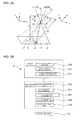
- FIG. 2A schematically shows a relation between the nadir camera 7A and one of the obliquely-downward cameras 7B including a capturing range adjacent to the capturing range of the nadir camera 7A.
- An image capturing distance D' of the obliquely-downward camera 7B is determined with reference to a distance between a principal point 12 of a lens of the obliquely-downward camera 7B and a photographic principal point 13 that is the center point of the capturing range in the target region 1.
- a reference numeral 14 denotes a lens of the nadir camera 7A
- a reference numeral 15 denotes the principal point of the lens
- a reference numeral 16 denotes a focus
- a reference numeral 17 denotes a photographic principal point of the nadir camera 7A
- a reference numeral D denotes an image capturing distance of the nadir camera 7A
- a reference numeral 18 denotes the lens of the obliquely-downward camera 7B
- a reference numeral 19 denotes a focus.
- the arrows showing the axis directions of a coordinate system in FIG. 2A respectively show the axis directions of the coordinate system based on the image capturing orientation of the cameras 7A and 7B.
- the obliquely-downward camera 7B maintains a predetermined capturing range by adjusting a field angle with the change of the focal length f'.
- a flying height of the airplane is determined in a stage of planning a capturing plan to be described later (S1 of FIG. 9 ), whereby the image capturing distance D of the nadir camera 7A shown in FIG. 2A is determined.
- the focal length f and the field angle of the nadir camera 7A are determined based on a desired ground resolution. If the obliquely-downward camera 7B is located at the same position as the nadir camera 7A, based on the field angel of the nadir camera 7A determined as described above, the image capturing angle and the field angle of the obliquely-downward camera 7B can be determined with reference to the side overlapped rate Rs.
- the image capturing distance D' of the obliquely-downward camera 7B can be obtained using a trigonometric function, based on the image capturing distance D of the nadir camera 7A.
- the focal length f' of the obliquely-downward camera 7B can also be determined based on a desired ground resolution.
- the computer constituting the focal length setting unit 8 includes, for example, a table in which the image capturing distance D (D') and the focal length f (f') are associated corresponding to the ground resolution and a table in which the focal length f of the nadir camera 7A and the image capturing angle of the obliquely-downward camera 7B are associated corresponding to the side overlapped rate Rs.
- the focal lengths f and f' of the nadir camera 7A and the obliquely-downward camera 7B and the image capturing angle of the obliquely-downward camera 7B are calculated using those tables.
- the focal lengths f and f' are set respectively to the nadir camera 7A and the obliquely-downward camera 7B based on the calculation result. After that, it is only necessary to change the image capturing orientation of the obliquely-downward camera 7B to the image capturing angle obtained by the calculation. For example, when the image capturing orientation of the obliquely-downward camera 7B can be controlled by the orientation holding unit 11, the focal length setting unit 8 may output an instruction to the orientation holding unit 11 so that the orientation of the obliquely-downward camera 7B is changed to the image capturing orientation at a predetermined image capturing angle.
- the airplane loaded with the image capturing device A is made to fly in the direction shown by the void arrow in FIG. 1B , and image capturing is performed at positions shown by white circles on the arrow, that is, at a predetermined positional interval.
- a single flight can cover a wide range by using a plurality of captured images (S2 of FIG. 9 ).
- Ro is an overlapped rate set between the captured images in the flight direction of each of the cameras 7 and, for example, 60% of the entire length, whereby the target region 1 is captured so as to be overlapped over the entire region.
- a GPS and an IMU Inertial Measurement Unit are mounted in the airplane loaded with the image capturing device A, whereby the position and orientation of the cameras 7 upon capturing (roll angle ⁇ , pitch angle ⁇ , and yaw angle ⁇ ) are recorded, so that external standardization factors of each of the divisionally-captured images 2 can be obtained.
- IMU Inertial Measurement Unit
- a plan for setting an airplane's flight path corresponding to, for example, the size of the target region 1 to be captured, the focal length f of each of the cameras 7 corresponding thereto, and the like is previously planned (S1 in FIG. 9 ).
- a GCP 20 Round Control Point, ground reference point
- FIG. 3A shows an example of the target region 1.
- Reference numerals 21 and 22 denote respectively elevated highways and buildings. Chain double-dashed lines are image capturing ranges covered by a single image capturing by the five cameras 7 of the image capturing device A.
- FIG. 3B for ease of understanding, regarding the captured images sequentially obtained accompanying the flight of the airplane, the ranges of only some divisionally-captured images 2' taken by the nadir camera 7A are overlapped with the target region 1 as shown by chain double-dashed lines. In FIG. 3B , the ranges of the divisionally-captured images 2' are slightly deviated in the direction perpendicular to the flight direction of the airplane.
- FIG. 4A is an enlarged view of the relevant portion of FIG. 3B . As described above, capturing overlap regions 4 are formed in the flight direction of the airplane in accordance with a predetermined overlapped rate Ro.
- FIG. 2B shows a block diagram of a computer constituted as an orthophoto image generating device B.
- the orthophotographic image generating device B has an input section 23 and an operation section 24.
- the input section 23 includes a captured image input part 23a, an image capturing condition input part 23b, and a ground reference point position data input part 23c.
- the captured image obtained as described above is input to the captured image input part 23a.
- the information of a camera position and a camera orientation by GPS and IMU at image capturing is input to the capturing condition input part 23b.
- the positional information of the GCP 20 is input to the ground reference point position data input part 23c.
- the operation section 24 has a tie point setting unit 24a, an elevation model generating part 24b, an inter-elevation model matching part 24c, an orthogonal projection transformation processing part 24d, and a mosaic processing part 24e.
- the divisionally-captured images 2 input to the captured image input part 23a are first extracted so that suitable regions included in the two or more divisionally-captured images 2 are set to tie points 25 by the tie point setting unit 24a.
- the tie points 25 are extracted only from between the divisionally-captured images 2 and 2 obtained by the cameras 7 with the same focal length f. Namely, tie points 25 have a function for associating the relative positions of the divisionally-captured images 2 and 2 arranged in the flight direction.
- the tie points 25 are shown by black circles in FIG. 4A .
- the elevation model generating part 24b generates, based on a plurality of captured images formed in a continuous strip form so as to be associated with the flight direction as described above, the information of the camera position and the camera orientation corresponding to individual divisionally-captured images 2 input to the image capturing condition input part 23b as described above, and the positional information of the GCP 20 displayed in the divisionally-captured image 2 and input to the image capturing condition input part 23b as described above, DSMs 3 (Digital Surface Models, elevation models) which are strip regions similar to the continuous strip captured images (S3 of FIG. 9 ).
- the DSM 3 can be generated by, for example, stereo matching utilizing the image capturing overlap region 4 ranging the entire target region 1 by virtue of the overlapped rate Ro.
- the matching accuracy can be enhanced by utilizing the information of the position and orientation of the cameras 7 and 7 constituting the image capturing overlap region 4. Further, by virtue of the use of the positional information of the GCP 20, the positional information can be imparted to a stereo model formed by matching.
- the GCP 20 is shown by a white circle in FIG. 4A , and the generated strip-shaped DSMs 3 are shown in FIG. 4B .
- the five strip-shaped DSMs 3 generated as above and corresponding to the five cameras 7 are matched by the inter-elevation model matching part 24c (S4 of FIG. 9 ), whereby DSM 5 ranging the entire wide target region 1 is generated.
- the inter-elevation model matching part 24c matches the adjacent strip-shaped DSMs 3 and 3, utilizing the overlap regions of the adjacent strip-shaped DSMs 3, that is, the image capturing overlap regions 4 generated in the direction perpendicular to the flight direction based on the side overlapped rate Rs.
- FIG. 5A selectively shows only the strip-shaped DSM 3, covering the central part of the target region 1, and strip-shaped DSM 3' adjacent to the right side of the DSM 3 of the central part in FIG. 4B .
- a mesh with an interval of, for example, 5 m is set to the overlap regions 4 of the strip-shaped DSMs 3 and 3' and the vicinity of the GCP 20.
- the coordinate values of each cell 6 corresponding to each other between the meshed DSMs 3 and 3' are adjusted to approximate between the DSMs 3 and 3', whereby the DSMs 3 and 3' are matched.
- FIG. 5B shows enlarged views of the relevant portions of the two strip-shaped DSMs 3 and 3' of FIG. 5A when the mesh is set on each of the entire regions of the DSMs 3 and 3'.
- one cell in the DSM 3 is indicated by 6A
- the other cell in the DSM 3' is indicated by 6B.
- the adjustment for approximation is performed only in the height direction, that is, the altitude direction.
- the coordinates value of each of cells 6A and 6B are(kXi, kYi, kZi)
- k represents a course number
- i represents a cell number.
- ka, kb, and kc are unknowns.
- kXi k + 1Xi
- the adjustment for approximation is applied to all the cells 6, 6, ..., belonging to, for example, the overlap region 4 between the DSMs 3 and 3' which are strip-shaped regions, and the overlap regions 4 of the DSMs 3 and 3' are matched.
- the positional relation of the DSMs 3 and 3' is adjusted in accordance with the matching. Since the coordinate values of the cell 6 near the GCP 20 are highly reliable, it is preferable that the cell 6 near the GCP 20 is adjusted while being weighted relative to the matching of the other cells 6 belonging to the overlap region 4.
- the DSM in which the strip-shaped DSMs 3 and 3' are matched in this way, and the DSM 3 based on the divisionally-captured image 2, obtained by another obliquely-downward camera 7B more distant from the capturing range of the nadir camera 7A, are matched, whereby the reliability can be further enhanced.
- a plurality of the DSMs 3 and 3' which are rectangular-shaped regions are matched as above, whereby the wide range DSM 5 shown in FIG. 6A ranging the entire target region 1 is obtained.
- a plurality of the rectangular-shaped captured images that is, the divisionally-captured images 2 arranged in the flight direction of a single camera 7 and associated by the tie points 25 are sequentially subjected to the orthogonal projection transformation processing utilizing the wide range DSM 5 by the orthogonal projection transformation processing part 24d (S5 in FIG. 9 ).
- a rectangular-shaped captured image obtained by associating the divisionally-captured images 2, obtained by the nadir camera 7A, by the tie points 25 are overlapped with the DSM 5 and shown by chain double-dashed lines.
- the orthogonal projection transformation processing part 24d is constituted of suitable commercial available orthogonal transformation software and transforms the captured image, taken by each camera 7 by center projection, into orthogonal projection.
- the orthogonal transformation as exemplified in FIG. 6B , the optical path of a camera 7'at image capturing is blocked by, for example, a high building existing in the target region 1. Therefore, when the coordinates of a white point of FIG. 7 is recognized as the coordinates of a black point, that is, when the positional information is not accurately reflected in the captured image, correction is performed using the altitude information of the DSM 5.
- the correction can be performed using a trigonometric function based on the inclination angle ⁇ of the optical path specified by, for example, the IMU and the orientation holding unit 11 and the height h of a building specified by the DSM 5.
- the captured images processed by the orthogonal projection transformation processing part 24d are shown in FIG. 8A .
- the captured images each have a rectangular shape corresponding to the capturing ranges continuous in the flight direction of each camera 7 as in the above case, and the image capturing overlap region 4 based on the side overlapped rate Rs is formed in each rectangular-shaped captured image.
- Those rectangular-shaped captured images are connected, utilizing the image capturing overlap region 4, by the mosaic processing part 24e constituted of suitable mosaic software (S6 in FIG. 9 ).
- the mosaic processing part 24e constituted of suitable mosaic software (S6 in FIG. 9 ).
- FIG. 8B a wide range orthophoto image obtained by integrating the entire target region 1 is generated.
- the orthophoto image can be output from the output section 26 of the orthophoto image generating device B.
- the entire target region 1 can be captured in a single flight; however, even when the target region 1 is divisionally-captured in a plurality of flights on different courses, the images obtained by a plurality of image capturing are synthesized by alignment of these courses, whereby the orthophoto image of the entire target region 1 can be similarly obtained.
- the captured images in the courses are synthesized by the mosaic processing part 24e, whereby the orthophoto image ranging the entire target region 1 can be obtained; however, when the images in the courses are synthesized before the formation of the DSM 3 using the GCP 20 and the tie points 25, the accuracy of the DSM 5 in the entire target region 1 can be further enhanced. In addition, the accuracy of the generated orthophoto image of the entire target region 1 can be further enhanced.
- the captured images which are taken by the single nadir camera 7A and the plurality of obliquely-downward camera 7B so as to be compounded like a belt, are obtained at a predetermined flying position whose positional information is obtained by the GPS; however, for example, the image capturing orientation and the like of the obliquely-downward camera 7B are changed, and image capturing can be performed so that the periphery of the image capturing range of the nadir camera 7A is surrounded by the capturing range of the obliquely-downward cameras 7B. In that case, the captured images obtained by the cameras 7 are compounded, whereby a relatively large rectangular-shaped captured image can be obtained.
- the obliquely-downward cameras 7B of the image capturing device A are disposed so as to be arranged along with the nadir camera 7A in the flight direction of an airplane, the capturing timing of each of the cameras 7 is rendered different in accordance with the flight speed, and the capturing point of the nadir camera 7A is made to be the same as the capturing point of the obliquely-downward camera 7B.
- This constitution can further enhance the accuracy of the DSM 3.
- the image capturing can be relatively easily performed, and a high quality orthophoto image can be obtained.
Landscapes
- Engineering & Computer Science (AREA)
- Multimedia (AREA)
- Physics & Mathematics (AREA)
- General Physics & Mathematics (AREA)
- Signal Processing (AREA)
- Theoretical Computer Science (AREA)
- Radar, Positioning & Navigation (AREA)
- Remote Sensing (AREA)
- Image Processing (AREA)
- Studio Devices (AREA)
- Image Analysis (AREA)
Applications Claiming Priority (2)
| Application Number | Priority Date | Filing Date | Title |
|---|---|---|---|
| JP2008010828A JP4970296B2 (ja) | 2008-01-21 | 2008-01-21 | オルソフォト画像の生成方法、および撮影装置 |
| PCT/JP2009/050808 WO2009093587A1 (ja) | 2008-01-21 | 2009-01-21 | オルソフォト画像の生成方法、および撮影装置 |
Publications (3)
| Publication Number | Publication Date |
|---|---|
| EP2247094A1 true EP2247094A1 (de) | 2010-11-03 |
| EP2247094A4 EP2247094A4 (de) | 2011-07-20 |
| EP2247094B1 EP2247094B1 (de) | 2013-08-14 |
Family
ID=40901095
Family Applications (1)
| Application Number | Title | Priority Date | Filing Date |
|---|---|---|---|
| EP09703910.1A Not-in-force EP2247094B1 (de) | 2008-01-21 | 2009-01-21 | Orthophotografisches bilderzeugungsverfahren und abbildungseinrichtung |
Country Status (5)
| Country | Link |
|---|---|
| US (1) | US8717361B2 (de) |
| EP (1) | EP2247094B1 (de) |
| JP (1) | JP4970296B2 (de) |
| CN (1) | CN101919235A (de) |
| WO (1) | WO2009093587A1 (de) |
Cited By (2)
| Publication number | Priority date | Publication date | Assignee | Title |
|---|---|---|---|---|
| CN104200527A (zh) * | 2014-09-02 | 2014-12-10 | 西安煤航信息产业有限公司 | 一种真正射影像的生成方法 |
| US9361660B2 (en) | 2011-05-23 | 2016-06-07 | Sony Corporation | Image processing device and method, supplement image generation device and method, program, and recording medium |
Families Citing this family (58)
| Publication number | Priority date | Publication date | Assignee | Title |
|---|---|---|---|---|
| US8665316B2 (en) * | 2009-11-24 | 2014-03-04 | Microsoft Corporation | Multi-resolution digital large format camera with multiple detector arrays |
| FR2954520B1 (fr) * | 2009-12-18 | 2012-09-21 | Thales Sa | Procede de designation d'une cible pour un armement a guidage terminal par imagerie |
| JP5550970B2 (ja) * | 2010-04-12 | 2014-07-16 | 住友重機械工業株式会社 | 画像生成装置及び操作支援システム |
| WO2012131151A1 (en) * | 2011-03-28 | 2012-10-04 | Nokia Corporation | Methods and apparatuses for generating a panoramic image |
| JP5775354B2 (ja) | 2011-04-28 | 2015-09-09 | 株式会社トプコン | 離着陸ターゲット装置及び自動離着陸システム |
| EP2527787B1 (de) | 2011-05-23 | 2019-09-11 | Kabushiki Kaisha TOPCON | Luftbildaufnahmeverfahren und Luftbildaufnahmevorrichtung |
| JP5882693B2 (ja) * | 2011-11-24 | 2016-03-09 | 株式会社トプコン | 航空写真撮像方法及び航空写真撮像装置 |
| CN102506824B (zh) * | 2011-10-14 | 2014-08-27 | 航天恒星科技有限公司 | 一种城市低空无人机系统生成数字正射影像图的方法 |
| IL216515A (en) | 2011-11-22 | 2015-02-26 | Israel Aerospace Ind Ltd | A system and method for processing images from a camera set |
| JP6122591B2 (ja) | 2012-08-24 | 2017-04-26 | 株式会社トプコン | 写真測量用カメラ及び航空写真装置 |
| EP2787319A1 (de) * | 2013-04-05 | 2014-10-08 | Leica Geosystems AG | Steuerung einer Bildauslösung zur Luftbilderfassung in Nadir-Ausrichtung für ein unbemanntes Fluggerät |
| US9437016B2 (en) * | 2013-08-07 | 2016-09-06 | Toshiba Medical Systems Corporation | Image domain pansharpening method and system for spectral CT with large pixel energy discriminating detectors |
| CN103646384B (zh) * | 2013-12-20 | 2016-06-22 | 江苏大学 | 一种遥感扫描成像平台飞行速度的优化方法 |
| CN103716541B (zh) * | 2013-12-23 | 2019-08-02 | 宇龙计算机通信科技(深圳)有限公司 | 一种拍摄大分辨率照片的方法及终端 |
| WO2015199772A2 (en) * | 2014-03-28 | 2015-12-30 | Konica Minolta Laboratory U.S.A., Inc. | Method and system of stitching aerial data using information from previous aerial images |
| US9185290B1 (en) | 2014-06-20 | 2015-11-10 | Nearmap Australia Pty Ltd | Wide-area aerial camera systems |
| US9641736B2 (en) | 2014-06-20 | 2017-05-02 | nearmap australia pty ltd. | Wide-area aerial camera systems |
| US9052571B1 (en) * | 2014-06-20 | 2015-06-09 | nearmap australia pty ltd. | Wide-area aerial camera systems |
| US9440750B2 (en) | 2014-06-20 | 2016-09-13 | nearmap australia pty ltd. | Wide-area aerial camera systems |
| JP6413542B2 (ja) * | 2014-09-22 | 2018-10-31 | 富士ゼロックス株式会社 | 画像処理装置及び画像処理プログラム |
| US11768508B2 (en) | 2015-02-13 | 2023-09-26 | Skydio, Inc. | Unmanned aerial vehicle sensor activation and correlation system |
| JP6498488B2 (ja) * | 2015-03-26 | 2019-04-10 | 株式会社パスコ | 法面点検方法、法面撮影装置、および車両 |
| CN107534724B (zh) * | 2015-04-20 | 2020-09-04 | 深圳市大疆创新科技有限公司 | 成像系统 |
| FR3038482B1 (fr) * | 2015-06-30 | 2017-08-11 | Parrot | Bloc camera apte a etre embarque dans un drone pour cartographier un terrain et procede de gestion de capture d'images par un bloc camera |
| CN105005993B (zh) * | 2015-07-08 | 2018-02-16 | 西安电子科技大学 | 一种基于异构投影的三维地形快速精确匹配方法 |
| CN105225241B (zh) * | 2015-09-25 | 2017-09-15 | 广州极飞科技有限公司 | 无人机深度图像的获取方法及无人机 |
| US9592912B1 (en) | 2016-03-08 | 2017-03-14 | Unmanned Innovation, Inc. | Ground control point assignment and determination system |
| CN105759558A (zh) * | 2016-04-15 | 2016-07-13 | 中国科学院上海技术物理研究所 | 一种大视场推扫式恒地元遥感相机系统 |
| WO2018160989A1 (en) * | 2017-03-03 | 2018-09-07 | Aqueti Incorporated | Multi-camera system for tracking one or more objects through a scene |
| JP6653674B2 (ja) * | 2017-03-14 | 2020-02-26 | 朝日航洋株式会社 | 桟橋上部工下面の検査装置、桟橋上部工下面の検査システムおよび桟橋上部工下面の検査方法 |
| JP6278544B1 (ja) * | 2017-03-22 | 2018-02-14 | 国立研究開発法人国立環境研究所 | モニタリング装置 |
| EP3635332A2 (de) * | 2017-05-10 | 2020-04-15 | Mobileye Vision Technologies Ltd. | Sichtquerfeld für autonome fahrzeugsysteme |
| KR101863188B1 (ko) * | 2017-10-26 | 2018-06-01 | (주)아세아항측 | 3차원 문화재 모델 구축 방법 |
| CN107862720B (zh) * | 2017-11-24 | 2020-05-22 | 北京华捷艾米科技有限公司 | 基于多地图融合的位姿优化方法及位姿优化系统 |
| TWI663577B (zh) | 2018-06-04 | 2019-06-21 | 宏碁股份有限公司 | 針對非平面螢幕之色不均瑕疵補償系統 |
| CN110581943B (zh) * | 2018-06-11 | 2021-04-02 | 宏碁股份有限公司 | 针对非平面屏幕的色不均瑕疵补偿系统 |
| CN109489640B (zh) * | 2018-09-30 | 2021-04-13 | 上海航天控制技术研究所 | 一种用于恒地元分辨率对地遥感的线列探测器 |
| FR3087037B1 (fr) * | 2018-10-03 | 2021-06-04 | Soletanche Freyssinet | Procede d'acquisition d'images |
| JP2020088821A (ja) * | 2018-11-30 | 2020-06-04 | エスゼット ディージェイアイ テクノロジー カンパニー リミテッドSz Dji Technology Co.,Ltd | 画像生成装置、画像生成方法、プログラム、及び記録媒体 |
| RU2712645C1 (ru) * | 2019-01-04 | 2020-01-30 | Родион Николаевич Юрьев | Геопозиционная мишень |
| KR102197654B1 (ko) * | 2019-01-09 | 2021-01-04 | 네이버랩스 주식회사 | 영상 처리 장치 및 이에 의한 진정사 영상 생성 방법 |
| WO2021046861A1 (zh) * | 2019-09-12 | 2021-03-18 | 深圳市大疆创新科技有限公司 | 正射影像生成方法、系统和存储介质 |
| CN112154484A (zh) * | 2019-09-12 | 2020-12-29 | 深圳市大疆创新科技有限公司 | 正射影像生成方法、系统和存储介质 |
| KR102117276B1 (ko) * | 2019-12-10 | 2020-06-01 | (주)태영정보시스템 | Dsm 데이터를 이용한 영상모자이크 작업시 접합선 생성 향상기법 |
| CN111750830B (zh) * | 2019-12-19 | 2023-02-14 | 广州极飞科技股份有限公司 | 地块测绘方法及测绘系统 |
| CN111415296B (zh) * | 2020-03-17 | 2024-01-19 | 东南数字经济发展研究院 | 一种无人机倾斜摄影的地面分辨率计算方法 |
| CN111415295B (zh) * | 2020-03-17 | 2024-01-12 | 东南数字经济发展研究院 | 一种倾斜摄影三维模型的拍摄分辨率正射图生成方法 |
| KR102426282B1 (ko) * | 2020-04-20 | 2022-07-29 | 한국국토정보공사 | 도로선형 기반의 3차원 공간객체 위치보정 방법 |
| JP7014261B2 (ja) * | 2020-06-15 | 2022-02-01 | ソニーグループ株式会社 | 制御方法及び制御装置 |
| CA3198865A1 (en) * | 2020-10-19 | 2022-04-28 | Pictometry International Corp. | Variable focal length multi-camera aerial imaging system and method |
| CN112509129B (zh) * | 2020-12-21 | 2022-12-30 | 神思电子技术股份有限公司 | 一种基于改进gan网络的空间视场图像生成方法 |
| KR102520189B1 (ko) * | 2021-03-02 | 2023-04-10 | 네이버랩스 주식회사 | 무인 비행체 또는 항공기에 의해 촬영된 항공 영상에 기반하여 hd 맵을 생성하는 방법 및 시스템 |
| CN112801044B (zh) * | 2021-03-11 | 2023-05-23 | 重庆紫光华山智安科技有限公司 | 视频图像处理方法、装置、视频客户端及解析平台 |
| US11670089B2 (en) | 2021-06-03 | 2023-06-06 | Not A Satellite Labs, LLC | Image modifications for crowdsourced surveillance |
| US11663911B2 (en) | 2021-06-03 | 2023-05-30 | Not A Satellite Labs, LLC | Sensor gap analysis |
| US20240104754A1 (en) * | 2021-12-27 | 2024-03-28 | Rakuten Group, Inc. | Information processing system, method and program |
| CN114268742B (zh) * | 2022-03-01 | 2022-05-24 | 北京瞭望神州科技有限公司 | 一种天眼芯片处理装置 |
| CN114937140B (zh) * | 2022-07-25 | 2022-11-04 | 深圳大学 | 面向大规模场景的图像渲染质量预测与路径规划系统 |
Family Cites Families (10)
| Publication number | Priority date | Publication date | Assignee | Title |
|---|---|---|---|---|
| US167709A (en) * | 1875-09-14 | Improvement in wooden frames for hinged awnings | ||
| CA2047525A1 (en) * | 1990-08-31 | 1992-03-01 | Gerald W. Plunk | Oblique photographic database generation |
| US6130705A (en) * | 1998-07-10 | 2000-10-10 | Recon/Optical, Inc. | Autonomous electro-optical framing camera system with constant ground resolution, unmanned airborne vehicle therefor, and methods of use |
| JP3251557B2 (ja) * | 1998-12-21 | 2002-01-28 | 国際航業株式会社 | 壁面の画像・損害・修復情報登録管理システム及び方法 |
| US6704460B1 (en) * | 2000-07-10 | 2004-03-09 | The United States Of America As Represented By The Secretary Of The Army | Remote mosaic imaging system having high-resolution, wide field-of-view and low bandwidth |
| JP4147059B2 (ja) * | 2002-07-03 | 2008-09-10 | 株式会社トプコン | キャリブレーション用データ測定装置、測定方法及び測定プログラム、並びにコンピュータ読取可能な記録媒体、画像データ処理装置 |
| WO2004028134A2 (en) * | 2002-09-20 | 2004-04-01 | M7 Visual Intelligence, Lp | Vehicule based data collection and porcessing system |
| US20050089213A1 (en) * | 2003-10-23 | 2005-04-28 | Geng Z. J. | Method and apparatus for three-dimensional modeling via an image mosaic system |
| IL163565A (en) * | 2004-08-16 | 2010-06-16 | Rafael Advanced Defense Sys | Airborne reconnaissance system |
| JP4356689B2 (ja) * | 2005-12-08 | 2009-11-04 | ソニー株式会社 | カメラシステム、カメラ制御装置、パノラマ画像作成方法及びコンピュータ・プログラム |
-
2008
- 2008-01-21 JP JP2008010828A patent/JP4970296B2/ja not_active Expired - Fee Related
-
2009
- 2009-01-21 CN CN200980102630.7A patent/CN101919235A/zh active Pending
- 2009-01-21 US US12/863,682 patent/US8717361B2/en not_active Expired - Fee Related
- 2009-01-21 EP EP09703910.1A patent/EP2247094B1/de not_active Not-in-force
- 2009-01-21 WO PCT/JP2009/050808 patent/WO2009093587A1/ja not_active Ceased
Non-Patent Citations (10)
| Title |
|---|
| CHEN W ET AL: "A Comprehensive Study on Urban True Orthorectification", IEEE TRANSACTIONS ON GEOSCIENCE AND REMOTE SENSING, IEEE, PISCATAWAY, NJ, US, vol. 43, no. 9, 1 September 2005 (2005-09-01), pages 2138-2147, XP011138222, * |
| GÜNAY A ET AL: "Semi-Automatic True Orthophoto Production by Using LIDAR Data", GEOSCIENCE AND REMOTE SENSING, IEEE INTERNATIONAL SYMPOSIUM, 1 January 2007 (2007-01-01), pages 2873-2876, XP007918578, * |
| HOHLE J: "Experiences with the production of digital orthophotos", PHOTOGRAMMETRIC ENGINEERING AND REMOTE SENSING, AMERICAN SOCIETY FOR PHOTOGRAMMETRY AND REMOTE SENSING, US, vol. 62, no. 10, 1 October 1996 (1996-10-01), pages 1189-1194, XP009148021, * |
| HONKAVAARA E ET AL: "Geometric test field calibration of digital photogrammetric sensors", ISPRS JOURNAL OF PHOTOGRAMMETRY AND REMOTE SENSING, AMSTERDAM, ELSEVIER, vol. 60, no. 6, 1 September 2006 (2006-09-01), pages 387-399, XP025081489, * |
| LEBERL ET AL: "The UltraCam large formataerial digital camera system", PROCEEDINGS OF THE AMERICAN SOCIETY FOR PHOTOGRAMMETRY & REMOTE SENSING, ANCHORAGE, ALASKA, 5-9 MAY, 2003,, 5 May 2003 (2003-05-05), page 6PP, XP009148007, * |
| MAYR W: "True orthoimages", GIM. GEODETICAL INFORMATION MAGAZINE, GEODETICAL INFORMATION & TRADING CENTRE, LEMMER, NL, vol. 16, 1 April 2002 (2002-04-01), pages 37-39, XP009148025, * |
| ROBERT ECKER: "Digital orthophoto generation based on a high-quality DTM", 19920101, vol. 1, 1 January 1992 (1992-01-01), pages 59-64, XP007918575, * |
| See also references of WO2009093587A1 * |
| WANPENG ZHANG ET AL: "DIGITAL ORTHOIMAGE FROM AIRBORNE LINE SCANNER IMAGERY UTILIZING FLIGHT PARAMETERS", PROC. SPIE, vol. 2357, 1 January 1994 (1994-01-01), pages 945-950, XP007918579, * |
| XIAOYE LIU ET AL: "LiDAR-Derived High Quality Ground Control Information and DEM for Image Orthorectification", GEOINFORMATICA , KLUWER ACADEMIC PUBLISHERS, vol. 11, no. 1, 4 January 2007 (2007-01-04), pages 37-53, XP019479821, * |
Cited By (2)
| Publication number | Priority date | Publication date | Assignee | Title |
|---|---|---|---|---|
| US9361660B2 (en) | 2011-05-23 | 2016-06-07 | Sony Corporation | Image processing device and method, supplement image generation device and method, program, and recording medium |
| CN104200527A (zh) * | 2014-09-02 | 2014-12-10 | 西安煤航信息产业有限公司 | 一种真正射影像的生成方法 |
Also Published As
| Publication number | Publication date |
|---|---|
| JP4970296B2 (ja) | 2012-07-04 |
| EP2247094B1 (de) | 2013-08-14 |
| US8717361B2 (en) | 2014-05-06 |
| EP2247094A4 (de) | 2011-07-20 |
| JP2009177251A (ja) | 2009-08-06 |
| WO2009093587A1 (ja) | 2009-07-30 |
| US20100295855A1 (en) | 2010-11-25 |
| CN101919235A (zh) | 2010-12-15 |
Similar Documents
| Publication | Publication Date | Title |
|---|---|---|
| US8717361B2 (en) | Method for generating orthophoto image | |
| JP5389964B2 (ja) | 地図情報生成装置 | |
| CN107492069B (zh) | 基于多镜头传感器的图像融合方法 | |
| CN103557841B (zh) | 一种提高多相机合成影像摄影测量精度的方法 | |
| US7149346B2 (en) | Three-dimensional database generating system and method for generating three-dimensional database | |
| JP4181800B2 (ja) | ステレオ画像を用いた地形計測システム及び記憶媒体並びにプログラム | |
| US11689808B2 (en) | Image synthesis system | |
| Doerstel et al. | Geometric calibration of the DMC: method and results | |
| JP2016194515A (ja) | 点群データ生成用画像の撮影方法、及び当該画像を用いた点群データ生成方法 | |
| CN107798668B (zh) | 基于rgb影像的无人机成像高光谱几何校正的方法及系统 | |
| CN110223233B (zh) | 一种基于图像拼接的无人机航拍建图方法 | |
| JP5458380B2 (ja) | 画像処理装置及び方法 | |
| JP2017026577A (ja) | 三次元測量写真の作成方法 | |
| CN113052974B (zh) | 物体三维表面的重建方法和装置 | |
| Nasrullah | Systematic analysis of unmanned aerial vehicle (UAV) derived product quality | |
| JP2004245741A (ja) | 空中写真測量方法 | |
| JP5991821B2 (ja) | 写真測量装置 | |
| JP7216994B2 (ja) | 現況測量図作成システム、方法及びプログラム | |
| KR100924008B1 (ko) | 수치도화 기술을 기반으로 한 항공사진의 고도화 방법 | |
| JP7042911B2 (ja) | Uav制御装置およびuav制御方法 | |
| JP6296444B2 (ja) | 点群画像による図化方法、及び点群画像による図化装置 | |
| KR100952136B1 (ko) | 경사영상의 외부표정요소 보정방법 및 이를 이용한 구조물의 3차원 정보를 측정하는 방법 | |
| CN111444385B (zh) | 一种基于影像角点匹配的电子地图实时视频镶嵌方法 | |
| Jacobsen et al. | Sub-camera calibration of a penta-camera | |
| Jacobsen | Calibration of optical satellite sensors |
Legal Events
| Date | Code | Title | Description |
|---|---|---|---|
| PUAI | Public reference made under article 153(3) epc to a published international application that has entered the european phase |
Free format text: ORIGINAL CODE: 0009012 |
|
| 17P | Request for examination filed |
Effective date: 20100819 |
|
| AK | Designated contracting states |
Kind code of ref document: A1 Designated state(s): AT BE BG CH CY CZ DE DK EE ES FI FR GB GR HR HU IE IS IT LI LT LU LV MC MK MT NL NO PL PT RO SE SI SK TR |
|
| AX | Request for extension of the european patent |
Extension state: AL BA RS |
|
| DAX | Request for extension of the european patent (deleted) | ||
| A4 | Supplementary search report drawn up and despatched |
Effective date: 20110620 |
|
| RIC1 | Information provided on ipc code assigned before grant |
Ipc: G06T 3/00 20060101ALI20110614BHEP Ipc: H04N 5/225 20060101AFI20090813BHEP Ipc: G06T 1/00 20060101ALI20110614BHEP |
|
| 17Q | First examination report despatched |
Effective date: 20120522 |
|
| GRAP | Despatch of communication of intention to grant a patent |
Free format text: ORIGINAL CODE: EPIDOSNIGR1 |
|
| GRAS | Grant fee paid |
Free format text: ORIGINAL CODE: EPIDOSNIGR3 |
|
| GRAA | (expected) grant |
Free format text: ORIGINAL CODE: 0009210 |
|
| AK | Designated contracting states |
Kind code of ref document: B1 Designated state(s): AT BE BG CH CY CZ DE DK EE ES FI FR GB GR HR HU IE IS IT LI LT LU LV MC MK MT NL NO PL PT RO SE SI SK TR |
|
| REG | Reference to a national code |
Ref country code: GB Ref legal event code: FG4D |
|
| REG | Reference to a national code |
Ref country code: AT Ref legal event code: REF Ref document number: 627409 Country of ref document: AT Kind code of ref document: T Effective date: 20130815 Ref country code: CH Ref legal event code: EP |
|
| REG | Reference to a national code |
Ref country code: IE Ref legal event code: FG4D |
|
| REG | Reference to a national code |
Ref country code: DE Ref legal event code: R096 Ref document number: 602009017959 Country of ref document: DE Effective date: 20131010 |
|
| REG | Reference to a national code |
Ref country code: AT Ref legal event code: MK05 Ref document number: 627409 Country of ref document: AT Kind code of ref document: T Effective date: 20130814 Ref country code: NL Ref legal event code: VDEP Effective date: 20130814 |
|
| REG | Reference to a national code |
Ref country code: LT Ref legal event code: MG4D |
|
| PG25 | Lapsed in a contracting state [announced via postgrant information from national office to epo] |
Ref country code: LT Free format text: LAPSE BECAUSE OF FAILURE TO SUBMIT A TRANSLATION OF THE DESCRIPTION OR TO PAY THE FEE WITHIN THE PRESCRIBED TIME-LIMIT Effective date: 20130814 Ref country code: IS Free format text: LAPSE BECAUSE OF FAILURE TO SUBMIT A TRANSLATION OF THE DESCRIPTION OR TO PAY THE FEE WITHIN THE PRESCRIBED TIME-LIMIT Effective date: 20131214 Ref country code: CY Free format text: LAPSE BECAUSE OF FAILURE TO SUBMIT A TRANSLATION OF THE DESCRIPTION OR TO PAY THE FEE WITHIN THE PRESCRIBED TIME-LIMIT Effective date: 20130911 Ref country code: PT Free format text: LAPSE BECAUSE OF FAILURE TO SUBMIT A TRANSLATION OF THE DESCRIPTION OR TO PAY THE FEE WITHIN THE PRESCRIBED TIME-LIMIT Effective date: 20131216 Ref country code: SE Free format text: LAPSE BECAUSE OF FAILURE TO SUBMIT A TRANSLATION OF THE DESCRIPTION OR TO PAY THE FEE WITHIN THE PRESCRIBED TIME-LIMIT Effective date: 20130814 Ref country code: NO Free format text: LAPSE BECAUSE OF FAILURE TO SUBMIT A TRANSLATION OF THE DESCRIPTION OR TO PAY THE FEE WITHIN THE PRESCRIBED TIME-LIMIT Effective date: 20131114 Ref country code: HR Free format text: LAPSE BECAUSE OF FAILURE TO SUBMIT A TRANSLATION OF THE DESCRIPTION OR TO PAY THE FEE WITHIN THE PRESCRIBED TIME-LIMIT Effective date: 20130814 Ref country code: AT Free format text: LAPSE BECAUSE OF FAILURE TO SUBMIT A TRANSLATION OF THE DESCRIPTION OR TO PAY THE FEE WITHIN THE PRESCRIBED TIME-LIMIT Effective date: 20130814 |
|
| PG25 | Lapsed in a contracting state [announced via postgrant information from national office to epo] |
Ref country code: GR Free format text: LAPSE BECAUSE OF FAILURE TO SUBMIT A TRANSLATION OF THE DESCRIPTION OR TO PAY THE FEE WITHIN THE PRESCRIBED TIME-LIMIT Effective date: 20131115 Ref country code: LV Free format text: LAPSE BECAUSE OF FAILURE TO SUBMIT A TRANSLATION OF THE DESCRIPTION OR TO PAY THE FEE WITHIN THE PRESCRIBED TIME-LIMIT Effective date: 20130814 Ref country code: BE Free format text: LAPSE BECAUSE OF FAILURE TO SUBMIT A TRANSLATION OF THE DESCRIPTION OR TO PAY THE FEE WITHIN THE PRESCRIBED TIME-LIMIT Effective date: 20130814 Ref country code: PL Free format text: LAPSE BECAUSE OF FAILURE TO SUBMIT A TRANSLATION OF THE DESCRIPTION OR TO PAY THE FEE WITHIN THE PRESCRIBED TIME-LIMIT Effective date: 20130814 Ref country code: FI Free format text: LAPSE BECAUSE OF FAILURE TO SUBMIT A TRANSLATION OF THE DESCRIPTION OR TO PAY THE FEE WITHIN THE PRESCRIBED TIME-LIMIT Effective date: 20130814 Ref country code: SI Free format text: LAPSE BECAUSE OF FAILURE TO SUBMIT A TRANSLATION OF THE DESCRIPTION OR TO PAY THE FEE WITHIN THE PRESCRIBED TIME-LIMIT Effective date: 20130814 |
|
| PG25 | Lapsed in a contracting state [announced via postgrant information from national office to epo] |
Ref country code: CY Free format text: LAPSE BECAUSE OF FAILURE TO SUBMIT A TRANSLATION OF THE DESCRIPTION OR TO PAY THE FEE WITHIN THE PRESCRIBED TIME-LIMIT Effective date: 20130814 |
|
| PG25 | Lapsed in a contracting state [announced via postgrant information from national office to epo] |
Ref country code: SK Free format text: LAPSE BECAUSE OF FAILURE TO SUBMIT A TRANSLATION OF THE DESCRIPTION OR TO PAY THE FEE WITHIN THE PRESCRIBED TIME-LIMIT Effective date: 20130814 Ref country code: EE Free format text: LAPSE BECAUSE OF FAILURE TO SUBMIT A TRANSLATION OF THE DESCRIPTION OR TO PAY THE FEE WITHIN THE PRESCRIBED TIME-LIMIT Effective date: 20130814 Ref country code: DK Free format text: LAPSE BECAUSE OF FAILURE TO SUBMIT A TRANSLATION OF THE DESCRIPTION OR TO PAY THE FEE WITHIN THE PRESCRIBED TIME-LIMIT Effective date: 20130814 Ref country code: RO Free format text: LAPSE BECAUSE OF FAILURE TO SUBMIT A TRANSLATION OF THE DESCRIPTION OR TO PAY THE FEE WITHIN THE PRESCRIBED TIME-LIMIT Effective date: 20130814 Ref country code: CZ Free format text: LAPSE BECAUSE OF FAILURE TO SUBMIT A TRANSLATION OF THE DESCRIPTION OR TO PAY THE FEE WITHIN THE PRESCRIBED TIME-LIMIT Effective date: 20130814 Ref country code: NL Free format text: LAPSE BECAUSE OF FAILURE TO SUBMIT A TRANSLATION OF THE DESCRIPTION OR TO PAY THE FEE WITHIN THE PRESCRIBED TIME-LIMIT Effective date: 20130814 |
|
| PG25 | Lapsed in a contracting state [announced via postgrant information from national office to epo] |
Ref country code: ES Free format text: LAPSE BECAUSE OF FAILURE TO SUBMIT A TRANSLATION OF THE DESCRIPTION OR TO PAY THE FEE WITHIN THE PRESCRIBED TIME-LIMIT Effective date: 20130814 Ref country code: IT Free format text: LAPSE BECAUSE OF FAILURE TO SUBMIT A TRANSLATION OF THE DESCRIPTION OR TO PAY THE FEE WITHIN THE PRESCRIBED TIME-LIMIT Effective date: 20130814 |
|
| PLBE | No opposition filed within time limit |
Free format text: ORIGINAL CODE: 0009261 |
|
| STAA | Information on the status of an ep patent application or granted ep patent |
Free format text: STATUS: NO OPPOSITION FILED WITHIN TIME LIMIT |
|
| 26N | No opposition filed |
Effective date: 20140515 |
|
| REG | Reference to a national code |
Ref country code: DE Ref legal event code: R097 Ref document number: 602009017959 Country of ref document: DE Effective date: 20140515 |
|
| PG25 | Lapsed in a contracting state [announced via postgrant information from national office to epo] |
Ref country code: LU Free format text: LAPSE BECAUSE OF FAILURE TO SUBMIT A TRANSLATION OF THE DESCRIPTION OR TO PAY THE FEE WITHIN THE PRESCRIBED TIME-LIMIT Effective date: 20140121 Ref country code: MC Free format text: LAPSE BECAUSE OF FAILURE TO SUBMIT A TRANSLATION OF THE DESCRIPTION OR TO PAY THE FEE WITHIN THE PRESCRIBED TIME-LIMIT Effective date: 20130814 |
|
| REG | Reference to a national code |
Ref country code: CH Ref legal event code: PL |
|
| GBPC | Gb: european patent ceased through non-payment of renewal fee |
Effective date: 20140121 |
|
| PG25 | Lapsed in a contracting state [announced via postgrant information from national office to epo] |
Ref country code: LI Free format text: LAPSE BECAUSE OF NON-PAYMENT OF DUE FEES Effective date: 20140131 Ref country code: CH Free format text: LAPSE BECAUSE OF NON-PAYMENT OF DUE FEES Effective date: 20140131 |
|
| REG | Reference to a national code |
Ref country code: FR Ref legal event code: ST Effective date: 20140930 |
|
| REG | Reference to a national code |
Ref country code: IE Ref legal event code: MM4A |
|
| PG25 | Lapsed in a contracting state [announced via postgrant information from national office to epo] |
Ref country code: FR Free format text: LAPSE BECAUSE OF NON-PAYMENT OF DUE FEES Effective date: 20140131 Ref country code: GB Free format text: LAPSE BECAUSE OF NON-PAYMENT OF DUE FEES Effective date: 20140121 |
|
| PG25 | Lapsed in a contracting state [announced via postgrant information from national office to epo] |
Ref country code: IE Free format text: LAPSE BECAUSE OF NON-PAYMENT OF DUE FEES Effective date: 20140121 |
|
| PG25 | Lapsed in a contracting state [announced via postgrant information from national office to epo] |
Ref country code: MT Free format text: LAPSE BECAUSE OF FAILURE TO SUBMIT A TRANSLATION OF THE DESCRIPTION OR TO PAY THE FEE WITHIN THE PRESCRIBED TIME-LIMIT Effective date: 20130814 |
|
| PG25 | Lapsed in a contracting state [announced via postgrant information from national office to epo] |
Ref country code: BG Free format text: LAPSE BECAUSE OF FAILURE TO SUBMIT A TRANSLATION OF THE DESCRIPTION OR TO PAY THE FEE WITHIN THE PRESCRIBED TIME-LIMIT Effective date: 20130814 |
|
| PG25 | Lapsed in a contracting state [announced via postgrant information from national office to epo] |
Ref country code: TR Free format text: LAPSE BECAUSE OF FAILURE TO SUBMIT A TRANSLATION OF THE DESCRIPTION OR TO PAY THE FEE WITHIN THE PRESCRIBED TIME-LIMIT Effective date: 20130814 Ref country code: HU Free format text: LAPSE BECAUSE OF FAILURE TO SUBMIT A TRANSLATION OF THE DESCRIPTION OR TO PAY THE FEE WITHIN THE PRESCRIBED TIME-LIMIT; INVALID AB INITIO Effective date: 20090121 |
|
| PGFP | Annual fee paid to national office [announced via postgrant information from national office to epo] |
Ref country code: DE Payment date: 20170120 Year of fee payment: 9 |
|
| PG25 | Lapsed in a contracting state [announced via postgrant information from national office to epo] |
Ref country code: MK Free format text: LAPSE BECAUSE OF FAILURE TO SUBMIT A TRANSLATION OF THE DESCRIPTION OR TO PAY THE FEE WITHIN THE PRESCRIBED TIME-LIMIT Effective date: 20130814 |
|
| REG | Reference to a national code |
Ref country code: DE Ref legal event code: R119 Ref document number: 602009017959 Country of ref document: DE |
|
| PG25 | Lapsed in a contracting state [announced via postgrant information from national office to epo] |
Ref country code: DE Free format text: LAPSE BECAUSE OF NON-PAYMENT OF DUE FEES Effective date: 20180801 |