EP2247094A1 - Orthophotographic image creating method and imaging device - Google Patents
Orthophotographic image creating method and imaging device Download PDFInfo
- Publication number
- EP2247094A1 EP2247094A1 EP09703910A EP09703910A EP2247094A1 EP 2247094 A1 EP2247094 A1 EP 2247094A1 EP 09703910 A EP09703910 A EP 09703910A EP 09703910 A EP09703910 A EP 09703910A EP 2247094 A1 EP2247094 A1 EP 2247094A1
- Authority
- EP
- European Patent Office
- Prior art keywords
- image
- camera
- capturing
- obliquely
- nadir
- Prior art date
- Legal status (The legal status is an assumption and is not a legal conclusion. Google has not performed a legal analysis and makes no representation as to the accuracy of the status listed.)
- Granted
Links
- 238000000034 method Methods 0.000 title claims abstract description 25
- 238000003384 imaging method Methods 0.000 title abstract description 7
- 230000009466 transformation Effects 0.000 claims description 12
- 238000009877 rendering Methods 0.000 claims description 4
- 238000006243 chemical reaction Methods 0.000 abstract description 3
- 238000010586 diagram Methods 0.000 abstract description 3
- 238000001444 catalytic combustion detection Methods 0.000 description 4
- 230000015572 biosynthetic process Effects 0.000 description 2
- 230000003287 optical effect Effects 0.000 description 2
- 238000010422 painting Methods 0.000 description 2
- 238000013329 compounding Methods 0.000 description 1
- 230000006866 deterioration Effects 0.000 description 1
- 230000000694 effects Effects 0.000 description 1
- 230000008030 elimination Effects 0.000 description 1
- 238000003379 elimination reaction Methods 0.000 description 1
- 230000007613 environmental effect Effects 0.000 description 1
- 230000010006 flight Effects 0.000 description 1
- 238000003702 image correction Methods 0.000 description 1
- 238000005259 measurement Methods 0.000 description 1
- 230000002194 synthesizing effect Effects 0.000 description 1
- 239000011800 void material Substances 0.000 description 1
Images


Classifications
-
- G06T3/153—
-
- G—PHYSICS
- G01—MEASURING; TESTING
- G01C—MEASURING DISTANCES, LEVELS OR BEARINGS; SURVEYING; NAVIGATION; GYROSCOPIC INSTRUMENTS; PHOTOGRAMMETRY OR VIDEOGRAMMETRY
- G01C11/00—Photogrammetry or videogrammetry, e.g. stereogrammetry; Photographic surveying
- G01C11/02—Picture taking arrangements specially adapted for photogrammetry or photographic surveying, e.g. controlling overlapping of pictures
-
- G06T3/06—
-
- H—ELECTRICITY
- H04—ELECTRIC COMMUNICATION TECHNIQUE
- H04N—PICTORIAL COMMUNICATION, e.g. TELEVISION
- H04N23/00—Cameras or camera modules comprising electronic image sensors; Control thereof
- H04N23/60—Control of cameras or camera modules
- H04N23/698—Control of cameras or camera modules for achieving an enlarged field of view, e.g. panoramic image capture
-
- H—ELECTRICITY
- H04—ELECTRIC COMMUNICATION TECHNIQUE
- H04N—PICTORIAL COMMUNICATION, e.g. TELEVISION
- H04N23/00—Cameras or camera modules comprising electronic image sensors; Control thereof
- H04N23/90—Arrangement of cameras or camera modules, e.g. multiple cameras in TV studios or sports stadiums
Definitions
- This invention relates to a method for generating an orthophoto image and a photographing device.
- An orthophoto image widely utilized for creation of a topographic map or as a photographic map is generated by applying an orthogonal projection transformation processing to a central perspective projection image obtained by capturing a target region from the air.
- the image capturing equipment tends to be shifted from the conventional analog camera to a digital camera for the purpose of, for example, improving operating efficiency.
- a UCD UltraCamD
- VEXCEL VEXCEL in Austria substitutes for the conventional analog aerial camera as an analog camera for use in capturing from an airplane.
- the UCD is classified into a so-called area sensor which records a predetermined area at a time as with the conventional analog aerial camera.
- the UCD is mounted with a plurality of CCDs and lenses in order to obtain a resolution and a capturing range equivalent to the analog aerial camera by means of an imaging device with an insufficient performance.
- a region to be captured is divisionally-captured as a plurality of panchromatic images, utilizing the CCDs and the lenses, whereby a wide range region is captured, and a ground resolution as the panchromatic image is improved.
- a color image with a lower resolution is obtained by a plurality of CCDs and lenses different from the above ones, and a so-called pan-sharpening processing for synthesizing with the panchromatic image is performed, whereby the color captured image can be obtained.
- Patent Document 1 describes a similar technique.
- a wall surface is merely captured, and the image capturing equipment is not mounted in a moving platform such as an aerial camera, the image capturing distance is not extremely large, and versatile coordinate information such as a ground coordinate system is not obtained.
- the entire wall painting is captured as an index image, and, at the same time, the wall painting is captured to be divided into divisional detailed images.
- the detailed images are standardized utilizing the corresponding points of the index image, and they are connected with each other with reference to the index image. The brightness and color tone of the connected image are adjusted with reference to the index image.
- Patent Document 1 Japanese Patent Application Laid-Open No. 2000-182059
- the image capturing using the UCD when a target region is divisionally-captured using a plurality of CCDs and lenses, that is, cameras, these cameras are made to converge on a single focal point, and they are operated as if it were a single analog aerial camera. Therefore, the image capturing using the UCD has a disadvantage that the cameras should be extremely precisely adjusted. Especially, in the image capturing from a moving platform such as an airplane, such a requirement may not be able to be satisfactorily satisfied under some environmental conditions such as an air current.
- the above objects are achieved by providing a method for generating an orthophoto image.
- the method includes divisionally-capturing a target region 1 from a platform such as an airplane by rendering viewing angles as being different from each other as well as rendering a focal length f as being different with reference to a predetermined ground resolution, thereafter generating an elevation model 5 of an entire target region in accordance with matching of elevation models 3 generated based on respective divisionally-captured images 2 among image capturing overlap regions 4 and 4, and generating an orthophoto image of the entire target region 1 by applying an orthogonal projection transformation processing to the respective divisionally-captured images 2 by use of altitude information of the elevation model 5.
- the wide range target region 1 is divisionally-captured so that the viewing angles from a platform such as an airplane are different from each other.
- the focal length f is different so that a predetermined ground resolution is satisfied.
- the focal length f is adjusted to thereby allow the divisionally-captured images 2 to have a predetermined ground resolution, whereby an image quality of a wide range captured image generated by combination of the divisionally-captured images 2, 2, ..., and ranging the entire target region 1 can be uniformized relative to the above prior art example, and, at the same time, the image quality can be extremely enhanced.
- a captured image obtained by central perspective projection can be represented by a coordinate system whose origin is a focus upon image capturing.
- the UCD using a plurality of digital cameras having a common focus has an advantage that only by adjusting rotation around the coordinate axes and scale, divisionally-captured images and elevation models, including altitude information represented as a numerical value and generated based thereon, can be well matched.
- the prior art matching method using an analog aerial camera can be diverted as it is.
- the present invention proposes a new matching method different from the prior art example merely recreating an analog camera.
- the elevation model 3 generated based on each divisionally-captured image that is, so-called digital terrain models or digital surface models are adjusted and matched, whereby suitable accuracy can be maintained.
- the present invention utilizes this constitution.
- the elevation model 3 in other directions than the direction at the nadir of the target region 1 are aligned so as to be expelled with reference to the elevation model 3 in the nadir direction. Namely, when expansion is performed in sequence to the outward direction based on the elevation model 3 in the nadir direction, the accuracy of the elevation model 5 of the entire target region can be further enhanced.
- the matching between the elevation model 3 and 3 can be performed, specifically, by matching between the suitable image capturing overlap regions 4 provided in the divisionally-captured images taken at different viewing angles from a platform.
- the elevation model 3 and 3 are matched utilizing a ground reference point imparting the altitude information to the elevation model 3, or a mesh is set on the image capturing overlap region 4, and the elevation model 3 and 3 can be matched in units of cells 6 in the mesh.
- the elevation model 3 and 3 generated based on the divisionally-captured images with different focal length f are matched, in the coordinate alignment in units of the cells 6, the best alignment between the cells 6 and 6 is performed, for example, in units of a plurality of cells 6, 6, ..., and therefore, a least square method is preferably used.
- the focal length f is different, the discrepancy between the elevation model 3 and 3 occurs not only on a plane, but also in the height direction, and therefore, it is preferable that the discrepancy is adjusted simultaneously in the longitudinal, lateral, and height directions.
- the discrepancy occurring in the height direction accounts for the majority, and therefore, the discrepancy is adjusted only in the height direction, whereby the correction efficiency of the discrepancy can be enhanced.
- an image capturing device which divisionally-captures a target region 1 from above with a plurality of cameras 7, 7, ..., can be utilized.
- the photographing device includes a nadir camera 7A whose orientation is held so that the nadir camera is directed in a nadir direction, an obliquely-downward camera 7B whose orientation is held so that the obliquely-downward camera is directed in an obliquely-downward direction, and an obliquely-downward camera setting unit 8 which sets a focal length f' of the obliquely-downward camera 7B, having a resolution of an object substantially equal to that of the nadir camera 7A, in accordance with an inclination angle of an orientation relative to the nadir direction.
- an image capturing device which can easily change a setting of capturing conditions corresponding to the change of the flying height is preferably used.
- the focal length f of the nadir camera 7A capturing in the direction at the nadir of the platform is determined
- the focal length f' of the obliquely-downward camera 7B capturing, from the other direction, that is, a platform, in the obliquely-downward direction with a predetermined angle is also uniquely determined by the depression angle.
- the obliquely-downward camera setting unit 8 setting the focal length f' of the obliquely-downward camera 7B in accordance with the focal length f of the nadir camera 7A is provided, and the load of the adjustment operation between the cameras 7, 7, ..., with the change of the flying height is reduced.
- the present invention can provide a method for generating an orthophoto image that can realize relatively easy capturing and generation of a high quality orthophoto image, and therefore, the creation of a topographic map and acquisition of a photographic map can be more efficiently performed. Further, an image capturing device, which is suitable for capturing utilizing the method for generating the orthophoto image, is provided, whereby the operating efficiency at capturing can be extremely enhanced.
- FIG. 1 shows an outline of divisionally-capturing of a target region 1.
- an orthophoto image of the extremely wide range of target region 1 is obtained using digital cameras 7.
- the wide target region 1 of the ground is divisionally-captured from an airplane (platform) (not shown) overhead to obtain a plurality of divisionally-captured images 2, and the divisionally-captured images 2 are then synthesized, whereby the orthophoto image of the extremely wide range of target region 1 is generated.
- the airplane is loaded with an image capturing device A, which captures a wide range by compounding divisionally-captured images in a direction perpendicular to the flight direction of the airplane, so that the entire target region 1 can be captured in a single flight.
- the image capturing device A has a directly-below camera 7A capturing at the nadir of the airplane and obliquely-downward cameras 7B capturing obliquely downward the airplane.
- the four obliquely-downward cameras 7B widen the capturing range of the nadir camera 7A in the direction perpendicular to the flight direction of the airplane, and the capturing ranges of a total of five cameras 7 are compounded substantially like a belt in the direction perpendicular to the flight direction.
- the image capturing range of each of the cameras 7 and the capturing ranges of the adjacent cameras 7 are partially overlapped, and a side overlapped rate Rs for use in the formation of a capturing overlap region 4 is set to, for example, 30% of the entire width.
- the side overlapped rate Rs is used for alignment of elevation model 3 and 3 generated based on divisionally-captured images 2.
- a relatively inexpensive "EOS-1 Ds Mark III" from Canon Inc. is used as each of the cameras 7. This camera has a high depiction performance, that is, about two million of the number of effective pixels, for example, and is loaded with a CMOS as an imaging device.
- the image capturing device A is provided with an orientation holding unit 11 which holds a predetermined capturing orientation of each of the cameras 7, that is, predetermined viewing angles from the airplane and a focal length setting unit (obliquely-downward camera setting unit 8) which manages a focal length f.
- the image capturing orientation of each of the cameras 7 and the relative position between the cameras 7 are held by the orientation holding unit 11 constituted as, for example, a camera stand.
- the image capturing orientation of the obliquely-downward camera 7B can be changed to an arbitrary capturing orientation.
- the focal length setting unit 8 is constituted of, for example, a luggable computer connected to each of the cameras 7 and sets and manages the focal length f of each of the cameras 7 by means of a program operating on the computer.
- the image capturing orientation of each of the cameras 7 can be detected by a sensor (not shown) connected to the orientation holding unit 11 and provided in the orientation control unit 11.
- the focal length setting unit 8 sets a focal length f', allowing the obliquely-downward cameras 7B to exhibit the ground resolution substantially equal to the ground resolution in the capturing performed by the nadir camera 7A, in accordance with the capturing orientation of each of the obliquely-downward cameras 7B, obtained from the orientation holding unit 11, and the focal length f set to the nadir camera 7A. More specifically, the image capturing orientation of each of the obliquely-downward cameras 7B is an inclination angle with respect to a nadir direction of the capturing orientation of each of the obliquely-downward cameras 7B.
- a region to be captured is regarded as a plane, and, for example, a relative image capturing distance ratio of each of the obliquely-downward cameras 7B to the nadir camera 7A is calculated using the viewing angles from an airplane flying in parallel with the plane.
- the focal length f' is set based on the ratio and the focal length f set to the nadir camera 7A so that each of the obliquely-downward cameras 7B can obtain the ground resolution equal to the ground resolution of the nadir camera 7A.
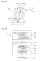
- FIG. 2A schematically shows a relation between the nadir camera 7A and one of the obliquely-downward cameras 7B including a capturing range adjacent to the capturing range of the nadir camera 7A.
- An image capturing distance D' of the obliquely-downward camera 7B is determined with reference to a distance between a principal point 12 of a lens of the obliquely-downward camera 7B and a photographic principal point 13 that is the center point of the capturing range in the target region 1.
- a reference numeral 14 denotes a lens of the nadir camera 7A
- a reference numeral 15 denotes the principal point of the lens
- a reference numeral 16 denotes a focus
- a reference numeral 17 denotes a photographic principal point of the nadir camera 7A
- a reference numeral D denotes an image capturing distance of the nadir camera 7A
- a reference numeral 18 denotes the lens of the obliquely-downward camera 7B
- a reference numeral 19 denotes a focus.
- the arrows showing the axis directions of a coordinate system in FIG. 2A respectively show the axis directions of the coordinate system based on the image capturing orientation of the cameras 7A and 7B.
- the obliquely-downward camera 7B maintains a predetermined capturing range by adjusting a field angle with the change of the focal length f'.
- a flying height of the airplane is determined in a stage of planning a capturing plan to be described later (S1 of FIG. 9 ), whereby the image capturing distance D of the nadir camera 7A shown in FIG. 2A is determined.
- the focal length f and the field angle of the nadir camera 7A are determined based on a desired ground resolution. If the obliquely-downward camera 7B is located at the same position as the nadir camera 7A, based on the field angel of the nadir camera 7A determined as described above, the image capturing angle and the field angle of the obliquely-downward camera 7B can be determined with reference to the side overlapped rate Rs.
- the image capturing distance D' of the obliquely-downward camera 7B can be obtained using a trigonometric function, based on the image capturing distance D of the nadir camera 7A.
- the focal length f' of the obliquely-downward camera 7B can also be determined based on a desired ground resolution.
- the computer constituting the focal length setting unit 8 includes, for example, a table in which the image capturing distance D (D') and the focal length f (f') are associated corresponding to the ground resolution and a table in which the focal length f of the nadir camera 7A and the image capturing angle of the obliquely-downward camera 7B are associated corresponding to the side overlapped rate Rs.
- the focal lengths f and f' of the nadir camera 7A and the obliquely-downward camera 7B and the image capturing angle of the obliquely-downward camera 7B are calculated using those tables.
- the focal lengths f and f' are set respectively to the nadir camera 7A and the obliquely-downward camera 7B based on the calculation result. After that, it is only necessary to change the image capturing orientation of the obliquely-downward camera 7B to the image capturing angle obtained by the calculation. For example, when the image capturing orientation of the obliquely-downward camera 7B can be controlled by the orientation holding unit 11, the focal length setting unit 8 may output an instruction to the orientation holding unit 11 so that the orientation of the obliquely-downward camera 7B is changed to the image capturing orientation at a predetermined image capturing angle.
- the airplane loaded with the image capturing device A is made to fly in the direction shown by the void arrow in FIG. 1B , and image capturing is performed at positions shown by white circles on the arrow, that is, at a predetermined positional interval.
- a single flight can cover a wide range by using a plurality of captured images (S2 of FIG. 9 ).
- Ro is an overlapped rate set between the captured images in the flight direction of each of the cameras 7 and, for example, 60% of the entire length, whereby the target region 1 is captured so as to be overlapped over the entire region.
- a GPS and an IMU Inertial Measurement Unit are mounted in the airplane loaded with the image capturing device A, whereby the position and orientation of the cameras 7 upon capturing (roll angle ⁇ , pitch angle ⁇ , and yaw angle ⁇ ) are recorded, so that external standardization factors of each of the divisionally-captured images 2 can be obtained.
- IMU Inertial Measurement Unit
- a plan for setting an airplane's flight path corresponding to, for example, the size of the target region 1 to be captured, the focal length f of each of the cameras 7 corresponding thereto, and the like is previously planned (S1 in FIG. 9 ).
- a GCP 20 Round Control Point, ground reference point
- FIG. 3A shows an example of the target region 1.
- Reference numerals 21 and 22 denote respectively elevated highways and buildings. Chain double-dashed lines are image capturing ranges covered by a single image capturing by the five cameras 7 of the image capturing device A.
- FIG. 3B for ease of understanding, regarding the captured images sequentially obtained accompanying the flight of the airplane, the ranges of only some divisionally-captured images 2' taken by the nadir camera 7A are overlapped with the target region 1 as shown by chain double-dashed lines. In FIG. 3B , the ranges of the divisionally-captured images 2' are slightly deviated in the direction perpendicular to the flight direction of the airplane.
- FIG. 4A is an enlarged view of the relevant portion of FIG. 3B . As described above, capturing overlap regions 4 are formed in the flight direction of the airplane in accordance with a predetermined overlapped rate Ro.
- FIG. 2B shows a block diagram of a computer constituted as an orthophoto image generating device B.
- the orthophotographic image generating device B has an input section 23 and an operation section 24.
- the input section 23 includes a captured image input part 23a, an image capturing condition input part 23b, and a ground reference point position data input part 23c.
- the captured image obtained as described above is input to the captured image input part 23a.
- the information of a camera position and a camera orientation by GPS and IMU at image capturing is input to the capturing condition input part 23b.
- the positional information of the GCP 20 is input to the ground reference point position data input part 23c.
- the operation section 24 has a tie point setting unit 24a, an elevation model generating part 24b, an inter-elevation model matching part 24c, an orthogonal projection transformation processing part 24d, and a mosaic processing part 24e.
- the divisionally-captured images 2 input to the captured image input part 23a are first extracted so that suitable regions included in the two or more divisionally-captured images 2 are set to tie points 25 by the tie point setting unit 24a.
- the tie points 25 are extracted only from between the divisionally-captured images 2 and 2 obtained by the cameras 7 with the same focal length f. Namely, tie points 25 have a function for associating the relative positions of the divisionally-captured images 2 and 2 arranged in the flight direction.
- the tie points 25 are shown by black circles in FIG. 4A .
- the elevation model generating part 24b generates, based on a plurality of captured images formed in a continuous strip form so as to be associated with the flight direction as described above, the information of the camera position and the camera orientation corresponding to individual divisionally-captured images 2 input to the image capturing condition input part 23b as described above, and the positional information of the GCP 20 displayed in the divisionally-captured image 2 and input to the image capturing condition input part 23b as described above, DSMs 3 (Digital Surface Models, elevation models) which are strip regions similar to the continuous strip captured images (S3 of FIG. 9 ).
- the DSM 3 can be generated by, for example, stereo matching utilizing the image capturing overlap region 4 ranging the entire target region 1 by virtue of the overlapped rate Ro.
- the matching accuracy can be enhanced by utilizing the information of the position and orientation of the cameras 7 and 7 constituting the image capturing overlap region 4. Further, by virtue of the use of the positional information of the GCP 20, the positional information can be imparted to a stereo model formed by matching.
- the GCP 20 is shown by a white circle in FIG. 4A , and the generated strip-shaped DSMs 3 are shown in FIG. 4B .
- the five strip-shaped DSMs 3 generated as above and corresponding to the five cameras 7 are matched by the inter-elevation model matching part 24c (S4 of FIG. 9 ), whereby DSM 5 ranging the entire wide target region 1 is generated.
- the inter-elevation model matching part 24c matches the adjacent strip-shaped DSMs 3 and 3, utilizing the overlap regions of the adjacent strip-shaped DSMs 3, that is, the image capturing overlap regions 4 generated in the direction perpendicular to the flight direction based on the side overlapped rate Rs.
- FIG. 5A selectively shows only the strip-shaped DSM 3, covering the central part of the target region 1, and strip-shaped DSM 3' adjacent to the right side of the DSM 3 of the central part in FIG. 4B .
- a mesh with an interval of, for example, 5 m is set to the overlap regions 4 of the strip-shaped DSMs 3 and 3' and the vicinity of the GCP 20.
- the coordinate values of each cell 6 corresponding to each other between the meshed DSMs 3 and 3' are adjusted to approximate between the DSMs 3 and 3', whereby the DSMs 3 and 3' are matched.
- FIG. 5B shows enlarged views of the relevant portions of the two strip-shaped DSMs 3 and 3' of FIG. 5A when the mesh is set on each of the entire regions of the DSMs 3 and 3'.
- one cell in the DSM 3 is indicated by 6A
- the other cell in the DSM 3' is indicated by 6B.
- the adjustment for approximation is performed only in the height direction, that is, the altitude direction.
- the coordinates value of each of cells 6A and 6B are(kXi, kYi, kZi)
- k represents a course number
- i represents a cell number.
- ka, kb, and kc are unknowns.
- kXi k + 1Xi
- the adjustment for approximation is applied to all the cells 6, 6, ..., belonging to, for example, the overlap region 4 between the DSMs 3 and 3' which are strip-shaped regions, and the overlap regions 4 of the DSMs 3 and 3' are matched.
- the positional relation of the DSMs 3 and 3' is adjusted in accordance with the matching. Since the coordinate values of the cell 6 near the GCP 20 are highly reliable, it is preferable that the cell 6 near the GCP 20 is adjusted while being weighted relative to the matching of the other cells 6 belonging to the overlap region 4.
- the DSM in which the strip-shaped DSMs 3 and 3' are matched in this way, and the DSM 3 based on the divisionally-captured image 2, obtained by another obliquely-downward camera 7B more distant from the capturing range of the nadir camera 7A, are matched, whereby the reliability can be further enhanced.
- a plurality of the DSMs 3 and 3' which are rectangular-shaped regions are matched as above, whereby the wide range DSM 5 shown in FIG. 6A ranging the entire target region 1 is obtained.
- a plurality of the rectangular-shaped captured images that is, the divisionally-captured images 2 arranged in the flight direction of a single camera 7 and associated by the tie points 25 are sequentially subjected to the orthogonal projection transformation processing utilizing the wide range DSM 5 by the orthogonal projection transformation processing part 24d (S5 in FIG. 9 ).
- a rectangular-shaped captured image obtained by associating the divisionally-captured images 2, obtained by the nadir camera 7A, by the tie points 25 are overlapped with the DSM 5 and shown by chain double-dashed lines.
- the orthogonal projection transformation processing part 24d is constituted of suitable commercial available orthogonal transformation software and transforms the captured image, taken by each camera 7 by center projection, into orthogonal projection.
- the orthogonal transformation as exemplified in FIG. 6B , the optical path of a camera 7'at image capturing is blocked by, for example, a high building existing in the target region 1. Therefore, when the coordinates of a white point of FIG. 7 is recognized as the coordinates of a black point, that is, when the positional information is not accurately reflected in the captured image, correction is performed using the altitude information of the DSM 5.
- the correction can be performed using a trigonometric function based on the inclination angle ⁇ of the optical path specified by, for example, the IMU and the orientation holding unit 11 and the height h of a building specified by the DSM 5.
- the captured images processed by the orthogonal projection transformation processing part 24d are shown in FIG. 8A .
- the captured images each have a rectangular shape corresponding to the capturing ranges continuous in the flight direction of each camera 7 as in the above case, and the image capturing overlap region 4 based on the side overlapped rate Rs is formed in each rectangular-shaped captured image.
- Those rectangular-shaped captured images are connected, utilizing the image capturing overlap region 4, by the mosaic processing part 24e constituted of suitable mosaic software (S6 in FIG. 9 ).
- the mosaic processing part 24e constituted of suitable mosaic software (S6 in FIG. 9 ).
- FIG. 8B a wide range orthophoto image obtained by integrating the entire target region 1 is generated.
- the orthophoto image can be output from the output section 26 of the orthophoto image generating device B.
- the entire target region 1 can be captured in a single flight; however, even when the target region 1 is divisionally-captured in a plurality of flights on different courses, the images obtained by a plurality of image capturing are synthesized by alignment of these courses, whereby the orthophoto image of the entire target region 1 can be similarly obtained.
- the captured images in the courses are synthesized by the mosaic processing part 24e, whereby the orthophoto image ranging the entire target region 1 can be obtained; however, when the images in the courses are synthesized before the formation of the DSM 3 using the GCP 20 and the tie points 25, the accuracy of the DSM 5 in the entire target region 1 can be further enhanced. In addition, the accuracy of the generated orthophoto image of the entire target region 1 can be further enhanced.
- the captured images which are taken by the single nadir camera 7A and the plurality of obliquely-downward camera 7B so as to be compounded like a belt, are obtained at a predetermined flying position whose positional information is obtained by the GPS; however, for example, the image capturing orientation and the like of the obliquely-downward camera 7B are changed, and image capturing can be performed so that the periphery of the image capturing range of the nadir camera 7A is surrounded by the capturing range of the obliquely-downward cameras 7B. In that case, the captured images obtained by the cameras 7 are compounded, whereby a relatively large rectangular-shaped captured image can be obtained.
- the obliquely-downward cameras 7B of the image capturing device A are disposed so as to be arranged along with the nadir camera 7A in the flight direction of an airplane, the capturing timing of each of the cameras 7 is rendered different in accordance with the flight speed, and the capturing point of the nadir camera 7A is made to be the same as the capturing point of the obliquely-downward camera 7B.
- This constitution can further enhance the accuracy of the DSM 3.
- the image capturing can be relatively easily performed, and a high quality orthophoto image can be obtained.
Abstract

Description
- This invention relates to a method for generating an orthophoto image and a photographing device.
- An orthophoto image widely utilized for creation of a topographic map or as a photographic map is generated by applying an orthogonal projection transformation processing to a central perspective projection image obtained by capturing a target region from the air. Recently, the image capturing equipment tends to be shifted from the conventional analog camera to a digital camera for the purpose of, for example, improving operating efficiency. For example, a UCD (UltraCamD) from VEXCEL in Austria substitutes for the conventional analog aerial camera as an analog camera for use in capturing from an airplane.
- The UCD is classified into a so-called area sensor which records a predetermined area at a time as with the conventional analog aerial camera. The UCD is mounted with a plurality of CCDs and lenses in order to obtain a resolution and a capturing range equivalent to the analog aerial camera by means of an imaging device with an insufficient performance. A region to be captured is divisionally-captured as a plurality of panchromatic images, utilizing the CCDs and the lenses, whereby a wide range region is captured, and a ground resolution as the panchromatic image is improved. In the conversion of the captured image into a color image, a color image with a lower resolution is obtained by a plurality of CCDs and lenses different from the above ones, and a so-called pan-sharpening processing for synthesizing with the panchromatic image is performed, whereby the color captured image can be obtained.
-
Patent Document 1 describes a similar technique. In this prior art example, a wall surface is merely captured, and the image capturing equipment is not mounted in a moving platform such as an aerial camera, the image capturing distance is not extremely large, and versatile coordinate information such as a ground coordinate system is not obtained. The entire wall painting is captured as an index image, and, at the same time, the wall painting is captured to be divided into divisional detailed images. The detailed images are standardized utilizing the corresponding points of the index image, and they are connected with each other with reference to the index image. The brightness and color tone of the connected image are adjusted with reference to the index image.
Patent Document 1: Japanese Patent Application Laid-Open No.2000-182059 - However, in the image capturing using the UCD, when a target region is divisionally-captured using a plurality of CCDs and lenses, that is, cameras, these cameras are made to converge on a single focal point, and they are operated as if it were a single analog aerial camera. Therefore, the image capturing using the UCD has a disadvantage that the cameras should be extremely precisely adjusted. Especially, in the image capturing from a moving platform such as an airplane, such a requirement may not be able to be satisfactorily satisfied under some environmental conditions such as an air current.
- In the above image capturing of a wide range target region with a single camera focus, especially in the image capturing from the air where the image capturing distance is extremely large, distortion occurring at a position far from the central area is large, and, in addition, the ground resolution is significantly different between the center and periphery of the target region, therefore resulting in lacking the uniformity of image quality.
- The present invention has been made in order to solve the above problems, and it is, therefore, an object of the present invention to provide a method for generating an orthophoto image that can realize relatively easy image capturing and generation of an orthophoto image with high image quality. Another object of the present invention is to provide a image capturing device suitable for image capturing utilizing the method for generating the orthophoto image.
- According to the present invention, the above objects are achieved by providing a method for generating an orthophoto image. The method includes divisionally-capturing a
target region 1 from a platform such as an airplane by rendering viewing angles as being different from each other as well as rendering a focal length f as being different with reference to a predetermined ground resolution, thereafter generating anelevation model 5 of an entire target region in accordance with matching ofelevation models 3 generated based on respective divisionally-capturedimages 2 among image capturingoverlap regions entire target region 1 by applying an orthogonal projection transformation processing to the respective divisionally-capturedimages 2 by use of altitude information of theelevation model 5. - In the present invention, the wide
range target region 1 is divisionally-captured so that the viewing angles from a platform such as an airplane are different from each other. In each image capturing, the focal length f is different so that a predetermined ground resolution is satisfied. Thus, it is not necessary to precisely adjust a plurality of cameras for the sake of converging on a single focal point, and it is enough that each camera for use in image capturing can hold the capturing orientation corresponding to a captured region in part; therefore, image capturing can be relatively easily performed. Further, the focal length f is adjusted to thereby allow the divisionally-capturedimages 2 to have a predetermined ground resolution, whereby an image quality of a wide range captured image generated by combination of the divisionally-capturedimages entire target region 1 can be uniformized relative to the above prior art example, and, at the same time, the image quality can be extremely enhanced. - In general, a captured image obtained by central perspective projection can be represented by a coordinate system whose origin is a focus upon image capturing. As described above, the UCD using a plurality of digital cameras having a common focus has an advantage that only by adjusting rotation around the coordinate axes and scale, divisionally-captured images and elevation models, including altitude information represented as a numerical value and generated based thereon, can be well matched. According to this constitution, the prior art matching method using an analog aerial camera can be diverted as it is. Meanwhile, the present invention proposes a new matching method different from the prior art example merely recreating an analog camera. For example, in a case of an aerial camera capturing at an extremely long capturing distance, even when the focal length f is slightly different between divisionally-captured images, the
elevation model 3 generated based on each divisionally-captured image, that is, so-called digital terrain models or digital surface models are adjusted and matched, whereby suitable accuracy can be maintained. The present invention utilizes this constitution. - Further, when color image capturing is performed as the above image capturing, deterioration of a radiometric resolution due to a pan-sharpening processing is eliminated, and an orthophoto image with well balanced ground resolution and color depth can be obtained. The elimination of the pan-sharpening processing can further enhance the operating efficiency.
- In addition, in the image capturing in which the viewing angles from a platform are different, when image capturing in the direction at the nadir of the platform is also performed, an image more similar to an orthogonal projection image can be obtained. Therefore, a highly accurate captured image and the
elevation model 5 with high accuracy based on the captured image can be obtained. In that case, theelevation model 3 in other directions than the direction at the nadir of thetarget region 1 are aligned so as to be expelled with reference to theelevation model 3 in the nadir direction. Namely, when expansion is performed in sequence to the outward direction based on theelevation model 3 in the nadir direction, the accuracy of theelevation model 5 of the entire target region can be further enhanced. - The matching between the
elevation model overlap regions 4 provided in the divisionally-captured images taken at different viewing angles from a platform. Theelevation model elevation model 3, or a mesh is set on the image capturingoverlap region 4, and theelevation model cells 6 in the mesh. As described above, in the present invention in which theelevation model cells 6, the best alignment between thecells cells elevation model - Further, in the generation of the orthophoto image, an image capturing device, which divisionally-captures a
target region 1 from above with a plurality ofcameras nadir camera 7A whose orientation is held so that the nadir camera is directed in a nadir direction, an obliquely-downward camera 7B whose orientation is held so that the obliquely-downward camera is directed in an obliquely-downward direction, and an obliquely-downwardcamera setting unit 8 which sets a focal length f' of the obliquely-downward camera 7B, having a resolution of an object substantially equal to that of thenadir camera 7A, in accordance with an inclination angle of an orientation relative to the nadir direction. - In the generation of an orthophoto image based on a an aerial photograph, in which the flying height of, for example, an airplane is changed in accordance with the size and terrain of the
target region 1 to be captured, an image capturing device which can easily change a setting of capturing conditions corresponding to the change of the flying height is preferably used. In the divisional capturing of thetarget region 1 from above or from the air when the ground resolution is uniform, when the focal length f of thenadir camera 7A capturing in the direction at the nadir of the platform is determined, the focal length f' of the obliquely-downward camera 7B capturing, from the other direction, that is, a platform, in the obliquely-downward direction with a predetermined angle is also uniquely determined by the depression angle. Considering this, in the present invention, the obliquely-downwardcamera setting unit 8 setting the focal length f' of the obliquely-downward camera 7B in accordance with the focal length f of thenadir camera 7A is provided, and the load of the adjustment operation between thecameras - As seen in the above description, the present invention can provide a method for generating an orthophoto image that can realize relatively easy capturing and generation of a high quality orthophoto image, and therefore, the creation of a topographic map and acquisition of a photographic map can be more efficiently performed. Further, an image capturing device, which is suitable for capturing utilizing the method for generating the orthophoto image, is provided, whereby the operating efficiency at capturing can be extremely enhanced.
-
FIG. 1 shows an outline of divisionally-capturing of atarget region 1. In this embodiment, an orthophoto image of the extremely wide range oftarget region 1 is obtained usingdigital cameras 7. Namely, thewide target region 1 of the ground is divisionally-captured from an airplane (platform) (not shown) overhead to obtain a plurality of divisionally-capturedimages 2, and the divisionally-capturedimages 2 are then synthesized, whereby the orthophoto image of the extremely wide range oftarget region 1 is generated. As shown inFIG. 1A , the airplane is loaded with an image capturing device A, which captures a wide range by compounding divisionally-captured images in a direction perpendicular to the flight direction of the airplane, so that theentire target region 1 can be captured in a single flight. - The image capturing device A has a directly-below
camera 7A capturing at the nadir of the airplane and obliquely-downward cameras 7B capturing obliquely downward the airplane. In this embodiment, the four obliquely-downward cameras 7B widen the capturing range of thenadir camera 7A in the direction perpendicular to the flight direction of the airplane, and the capturing ranges of a total of fivecameras 7 are compounded substantially like a belt in the direction perpendicular to the flight direction. The image capturing range of each of thecameras 7 and the capturing ranges of theadjacent cameras 7 are partially overlapped, and a side overlapped rate Rs for use in the formation of a capturingoverlap region 4 is set to, for example, 30% of the entire width. As described later, the side overlapped rate Rs is used for alignment ofelevation model images 2. As each of thecameras 7, a relatively inexpensive "EOS-1 Ds Mark III" from Canon Inc. is used. This camera has a high depiction performance, that is, about two million of the number of effective pixels, for example, and is loaded with a CMOS as an imaging device. - The image capturing device A is provided with an orientation holding unit 11 which holds a predetermined capturing orientation of each of the
cameras 7, that is, predetermined viewing angles from the airplane and a focal length setting unit (obliquely-downward camera setting unit 8) which manages a focal length f. The image capturing orientation of each of thecameras 7 and the relative position between thecameras 7 are held by the orientation holding unit 11 constituted as, for example, a camera stand. The image capturing orientation of the obliquely-downward camera 7B can be changed to an arbitrary capturing orientation. - The focal
length setting unit 8 is constituted of, for example, a luggable computer connected to each of thecameras 7 and sets and manages the focal length f of each of thecameras 7 by means of a program operating on the computer. The image capturing orientation of each of thecameras 7 can be detected by a sensor (not shown) connected to the orientation holding unit 11 and provided in the orientation control unit 11. The focallength setting unit 8 sets a focal length f', allowing the obliquely-downward cameras 7B to exhibit the ground resolution substantially equal to the ground resolution in the capturing performed by thenadir camera 7A, in accordance with the capturing orientation of each of the obliquely-downward cameras 7B, obtained from the orientation holding unit 11, and the focal length f set to thenadir camera 7A. More specifically, the image capturing orientation of each of the obliquely-downward cameras 7B is an inclination angle with respect to a nadir direction of the capturing orientation of each of the obliquely-downward cameras 7B. - Namely, a region to be captured is regarded as a plane, and, for example, a relative image capturing distance ratio of each of the obliquely-
downward cameras 7B to thenadir camera 7A is calculated using the viewing angles from an airplane flying in parallel with the plane. The focal length f' is set based on the ratio and the focal length f set to thenadir camera 7A so that each of the obliquely-downward cameras 7B can obtain the ground resolution equal to the ground resolution of thenadir camera 7A.FIG. 2A schematically shows a relation between thenadir camera 7A and one of the obliquely-downward cameras 7B including a capturing range adjacent to the capturing range of thenadir camera 7A. An image capturing distance D' of the obliquely-downward camera 7B is determined with reference to a distance between aprincipal point 12 of a lens of the obliquely-downward camera 7B and a photographicprincipal point 13 that is the center point of the capturing range in thetarget region 1. InFIG. 2A , areference numeral 14 denotes a lens of thenadir camera 7A, areference numeral 15 denotes the principal point of the lens, areference numeral 16 denotes a focus, areference numeral 17 denotes a photographic principal point of thenadir camera 7A, a reference numeral D denotes an image capturing distance of thenadir camera 7A, areference numeral 18 denotes the lens of the obliquely-downward camera 7B, and areference numeral 19 denotes a focus. The arrows showing the axis directions of a coordinate system inFIG. 2A respectively show the axis directions of the coordinate system based on the image capturing orientation of thecameras downward camera 7B maintains a predetermined capturing range by adjusting a field angle with the change of the focal length f'. - Specifically, for example, a flying height of the airplane is determined in a stage of planning a capturing plan to be described later (S1 of
FIG. 9 ), whereby the image capturing distance D of thenadir camera 7A shown inFIG. 2A is determined. When the image capturing distance D is determined, the focal length f and the field angle of thenadir camera 7A are determined based on a desired ground resolution. If the obliquely-downward camera 7B is located at the same position as thenadir camera 7A, based on the field angel of thenadir camera 7A determined as described above, the image capturing angle and the field angle of the obliquely-downward camera 7B can be determined with reference to the side overlapped rate Rs. When the image capturing angle of the obliquely-downward camera 7B is determined as described above, the image capturing distance D' of the obliquely-downward camera 7B can be obtained using a trigonometric function, based on the image capturing distance D of thenadir camera 7A. When the image capturing distance D' is determined, the focal length f' of the obliquely-downward camera 7B can also be determined based on a desired ground resolution. - The computer constituting the focal
length setting unit 8 includes, for example, a table in which the image capturing distance D (D') and the focal length f (f') are associated corresponding to the ground resolution and a table in which the focal length f of thenadir camera 7A and the image capturing angle of the obliquely-downward camera 7B are associated corresponding to the side overlapped rate Rs. When the flying height as the image capturing distance D is input while the ground resolution and the side overlapped rate Rs are previously set, the focal lengths f and f' of thenadir camera 7A and the obliquely-downward camera 7B and the image capturing angle of the obliquely-downward camera 7B are calculated using those tables. The focal lengths f and f' are set respectively to thenadir camera 7A and the obliquely-downward camera 7B based on the calculation result. After that, it is only necessary to change the image capturing orientation of the obliquely-downward camera 7B to the image capturing angle obtained by the calculation. For example, when the image capturing orientation of the obliquely-downward camera 7B can be controlled by the orientation holding unit 11, the focallength setting unit 8 may output an instruction to the orientation holding unit 11 so that the orientation of the obliquely-downward camera 7B is changed to the image capturing orientation at a predetermined image capturing angle. - The airplane loaded with the image capturing device A is made to fly in the direction shown by the void arrow in
FIG. 1B , and image capturing is performed at positions shown by white circles on the arrow, that is, at a predetermined positional interval. In that case, as shown inFIG. 1 B , a single flight can cover a wide range by using a plurality of captured images (S2 ofFIG. 9 ). InFIG. 1B , Ro is an overlapped rate set between the captured images in the flight direction of each of thecameras 7 and, for example, 60% of the entire length, whereby thetarget region 1 is captured so as to be overlapped over the entire region. A GPS and an IMU (Inertial Measurement Unit) are mounted in the airplane loaded with the image capturing device A, whereby the position and orientation of thecameras 7 upon capturing (roll angle ω, pitch angle φ, and yaw angle κ) are recorded, so that external standardization factors of each of the divisionally-capturedimages 2 can be obtained. - In the image capturing using the image capturing device A and the airplane, a plan for setting an airplane's flight path corresponding to, for example, the size of the
target region 1 to be captured, the focal length f of each of thecameras 7 corresponding thereto, and the like is previously planned (S1 inFIG. 9 ). A GCP 20 (Ground Control Point, ground reference point) in which a plan position and an altitude have been previously measured by control point survey is set to thetarget region 1.FIG. 3A shows an example of thetarget region 1.Reference numerals cameras 7 of the image capturing device A. - In
FIG. 3B , for ease of understanding, regarding the captured images sequentially obtained accompanying the flight of the airplane, the ranges of only some divisionally-captured images 2' taken by thenadir camera 7A are overlapped with thetarget region 1 as shown by chain double-dashed lines. InFIG. 3B , the ranges of the divisionally-captured images 2' are slightly deviated in the direction perpendicular to the flight direction of the airplane.FIG. 4A is an enlarged view of the relevant portion ofFIG. 3B . As described above, capturingoverlap regions 4 are formed in the flight direction of the airplane in accordance with a predetermined overlapped rate Ro. - In the following description, the processing procedure of the present invention is illustrated for ease of understanding; however, in fact, graphing as exemplified is not required, and the processing is performed only by calculation for the divisionally-captured
images 2. The following method can be automatically performed by a computer operating a program described with the following procedure.FIG. 2B shows a block diagram of a computer constituted as an orthophoto image generating device B. - The orthophotographic image generating device B has an
input section 23 and anoperation section 24. Theinput section 23 includes a capturedimage input part 23a, an image capturingcondition input part 23b, and a ground reference point position datainput part 23c. The captured image obtained as described above is input to the capturedimage input part 23a. The information of a camera position and a camera orientation by GPS and IMU at image capturing is input to the capturingcondition input part 23b. The positional information of theGCP 20 is input to the ground reference point position datainput part 23c. - The
operation section 24 has a tiepoint setting unit 24a, an elevationmodel generating part 24b, an inter-elevationmodel matching part 24c, an orthogonal projectiontransformation processing part 24d, and a mosaic processing part 24e. As described above, the divisionally-capturedimages 2 input to the capturedimage input part 23a are first extracted so that suitable regions included in the two or more divisionally-capturedimages 2 are set to tiepoints 25 by the tiepoint setting unit 24a. The tie points 25 are extracted only from between the divisionally-capturedimages cameras 7 with the same focal length f. Namely, tie points 25 have a function for associating the relative positions of the divisionally-capturedimages FIG. 4A . - The elevation
model generating part 24b generates, based on a plurality of captured images formed in a continuous strip form so as to be associated with the flight direction as described above, the information of the camera position and the camera orientation corresponding to individual divisionally-capturedimages 2 input to the image capturingcondition input part 23b as described above, and the positional information of theGCP 20 displayed in the divisionally-capturedimage 2 and input to the image capturingcondition input part 23b as described above, DSMs 3 (Digital Surface Models, elevation models) which are strip regions similar to the continuous strip captured images (S3 ofFIG. 9 ). TheDSM 3 can be generated by, for example, stereo matching utilizing the image capturingoverlap region 4 ranging theentire target region 1 by virtue of the overlapped rate Ro. In the stereo matching, the matching accuracy can be enhanced by utilizing the information of the position and orientation of thecameras overlap region 4. Further, by virtue of the use of the positional information of theGCP 20, the positional information can be imparted to a stereo model formed by matching. TheGCP 20 is shown by a white circle inFIG. 4A , and the generated strip-shapedDSMs 3 are shown inFIG. 4B . - The five strip-shaped
DSMs 3 generated as above and corresponding to the fivecameras 7 are matched by the inter-elevationmodel matching part 24c (S4 ofFIG. 9 ), wherebyDSM 5 ranging the entirewide target region 1 is generated. The inter-elevationmodel matching part 24c matches the adjacent strip-shapedDSMs DSMs 3, that is, the image capturingoverlap regions 4 generated in the direction perpendicular to the flight direction based on the side overlapped rate Rs.FIG. 5A selectively shows only the strip-shapedDSM 3, covering the central part of thetarget region 1, and strip-shaped DSM 3' adjacent to the right side of theDSM 3 of the central part inFIG. 4B . - In the matching between the
DSMs 3 and 3', a mesh with an interval of, for example, 5 m is set to theoverlap regions 4 of the strip-shapedDSMs 3 and 3' and the vicinity of theGCP 20. The coordinate values of eachcell 6 corresponding to each other between the meshed DSMs 3 and 3' are adjusted to approximate between theDSMs 3 and 3', whereby theDSMs 3 and 3' are matched.FIG. 5B shows enlarged views of the relevant portions of the two strip-shapedDSMs 3 and 3' ofFIG. 5A when the mesh is set on each of the entire regions of theDSMs 3 and 3'. When the size of thecell 6 is larger than the size of a pixel of the captured image, as the coordinate value of each of thecells 6, the coordinate value of the pixel of the central part of thecell 6 can be used. - As shown in
FIG. 5B , regarding thecells 6 belonging to theoverlap region 4 of theDSMs 3 and 3' to be adjusted to approximate each other, one cell in theDSM 3 is indicated by 6A, and the other cell in the DSM 3' is indicated by 6B. In this embodiment, considering the operating efficiency, the adjustment for approximation is performed only in the height direction, that is, the altitude direction. When the coordinates value of each ofcells - Specifically, a, b, and c satisfying such an equation that kZi + ka + kb·kXi + kc·kYi = k + 1Zi + k + 1a + k + 1b·k + 1Xi + k + 1c·k + 1Yi are obtained based on the primary expression, whereby the adjustment for approximation is performed. However, kXi = k + 1Xi and kYi = k + 1Yi are required. The adjustment for approximation is applied to all the
cells overlap region 4 between theDSMs 3 and 3' which are strip-shaped regions, and theoverlap regions 4 of theDSMs 3 and 3' are matched. The positional relation of theDSMs 3 and 3' is adjusted in accordance with the matching. Since the coordinate values of thecell 6 near theGCP 20 are highly reliable, it is preferable that thecell 6 near theGCP 20 is adjusted while being weighted relative to the matching of theother cells 6 belonging to theoverlap region 4. - In the matching between the strip-shaped
DSMs 3 and 3', first, theDSM 3 based on the divisionally-captured image obtained by the highlyreliable nadir camera 7A and the DSM 3' based on the divisionally-captured image, obtained by the obliquely-downward camera7B capturing a range included in thetarget region 1 and adjacent to the capturing range of thenadir camera 7A, are matched. Thereafter, the DSM, in which the strip-shapedDSMs 3 and 3' are matched in this way, and theDSM 3 based on the divisionally-capturedimage 2, obtained by another obliquely-downward camera 7B more distant from the capturing range of thenadir camera 7A, are matched, whereby the reliability can be further enhanced. - A plurality of the
DSMs 3 and 3' which are rectangular-shaped regions are matched as above, whereby thewide range DSM 5 shown inFIG. 6A ranging theentire target region 1 is obtained. Thereafter, in theoperation section 24, a plurality of the rectangular-shaped captured images, that is, the divisionally-capturedimages 2 arranged in the flight direction of asingle camera 7 and associated by the tie points 25 are sequentially subjected to the orthogonal projection transformation processing utilizing thewide range DSM 5 by the orthogonal projectiontransformation processing part 24d (S5 inFIG. 9 ). InFIG. 6A , a rectangular-shaped captured image obtained by associating the divisionally-capturedimages 2, obtained by thenadir camera 7A, by the tie points 25 are overlapped with theDSM 5 and shown by chain double-dashed lines. - The orthogonal projection
transformation processing part 24d is constituted of suitable commercial available orthogonal transformation software and transforms the captured image, taken by eachcamera 7 by center projection, into orthogonal projection. In the orthogonal transformation, as exemplified inFIG. 6B , the optical path of a camera 7'at image capturing is blocked by, for example, a high building existing in thetarget region 1. Therefore, when the coordinates of a white point ofFIG. 7 is recognized as the coordinates of a black point, that is, when the positional information is not accurately reflected in the captured image, correction is performed using the altitude information of theDSM 5. As shown inFIG. 7 , the correction can be performed using a trigonometric function based on the inclination angle θ of the optical path specified by, for example, the IMU and the orientation holding unit 11 and the height h of a building specified by theDSM 5. - The captured images processed by the orthogonal projection
transformation processing part 24d are shown inFIG. 8A . In this state, the captured images each have a rectangular shape corresponding to the capturing ranges continuous in the flight direction of eachcamera 7 as in the above case, and the image capturingoverlap region 4 based on the side overlapped rate Rs is formed in each rectangular-shaped captured image. Those rectangular-shaped captured images are connected, utilizing the image capturingoverlap region 4, by the mosaic processing part 24e constituted of suitable mosaic software (S6 inFIG. 9 ). According to this constitution, as shown inFIG. 8B , a wide range orthophoto image obtained by integrating theentire target region 1 is generated. The orthophoto image can be output from theoutput section 26 of the orthophoto image generating device B. - In the above description, the
entire target region 1 can be captured in a single flight; however, even when thetarget region 1 is divisionally-captured in a plurality of flights on different courses, the images obtained by a plurality of image capturing are synthesized by alignment of these courses, whereby the orthophoto image of theentire target region 1 can be similarly obtained. In that case, the captured images in the courses are synthesized by the mosaic processing part 24e, whereby the orthophoto image ranging theentire target region 1 can be obtained; however, when the images in the courses are synthesized before the formation of theDSM 3 using theGCP 20 and the tie points 25, the accuracy of theDSM 5 in theentire target region 1 can be further enhanced. In addition, the accuracy of the generated orthophoto image of theentire target region 1 can be further enhanced. - Further, in the above description, the captured images, which are taken by the
single nadir camera 7A and the plurality of obliquely-downward camera 7B so as to be compounded like a belt, are obtained at a predetermined flying position whose positional information is obtained by the GPS; however, for example, the image capturing orientation and the like of the obliquely-downward camera 7B are changed, and image capturing can be performed so that the periphery of the image capturing range of thenadir camera 7A is surrounded by the capturing range of the obliquely-downward cameras 7B. In that case, the captured images obtained by thecameras 7 are compounded, whereby a relatively large rectangular-shaped captured image can be obtained. - Furthermore, the obliquely-
downward cameras 7B of the image capturing device A are disposed so as to be arranged along with thenadir camera 7A in the flight direction of an airplane, the capturing timing of each of thecameras 7 is rendered different in accordance with the flight speed, and the capturing point of thenadir camera 7A is made to be the same as the capturing point of the obliquely-downward camera 7B. This constitution can further enhance the accuracy of theDSM 3. - According to the present invention, mainly when an orthophoto image is utilized for creation of a topographic map, or when the orthophoto image is utilized as a photographic map, the image capturing can be relatively easily performed, and a high quality orthophoto image can be obtained.
-
-
FIG. 1 is a view showing an image capturing device and image capturing conditions using the image capturing device; -
FIG. 2 is a view showing an outline of a method for generating an orthophoto image,FIG. 2A is a view for explaining a relation between a focal length and an image capturing distance upon image capturing and the like, andFIG. 2B is a block diagram of an orthophoto image generating device; -
FIG. 3 is a view for explaining image capturing conditions of a target region; -
FIG. 4 is a view for explaining steps of generating rectangular-shaped elevation models respectively corresponding to images captured by cameras; -
FIG. 5 is a view for explaining steps of matching the elevation models generated based on the images captured by the cameras; -
FIG. 6 is a view for explaining a situation that a captured image having a rectangular shape large in size in a flight direction is subjected to an orthogonal projection transformation processing, using an elevation model ranging the entire target region; -
FIG. 7 is a view for explaining an image correction in an orthogonal projection transformation processing step; -
FIG. 8 is a view for explaining orthophoto images of captured images each having a rectangular shape large in size in the flight direction and an orthophoto image of the entire target region; and -
FIG. 9 is a view showing a procedure of generating the orthophoto image. -
- 1
- Target region
- 2
- Divisionally-captured image
- 3
- Elevation model generated based on each captured image
- 4
- Image capturing overlap region
- 5
- Elevation model of entire target region
- 6
- Cell
- 7
- Camera
- 7A
- Nadir camera
- 7B
- Obliquely-downward camera
- 8
- Obliquely-downward camera setting part
- f
- Focal length
Claims (7)
- A method for generating an orthophoto image comprising:divisionally-capturing a target region from a platform such as an airplane by rendering viewing angles as being different from each other as well as rendering a focal length as being different with reference to a predetermined ground resolution; thereaftergenerating an elevation model of an entire target region in accordance with matching of elevation models generated based on respective divisionally-captured images among image capturing overlap regions; andgenerating an orthophoto image of the entire target region by applying an orthogonal projection transformation processing to the respective divisionally-captured images by use of altitude information of the elevation model.
- The method for generating an orthophoto image according to claim 1, wherein
in the divisionally-capturing, focal lengths are set respectively, while ground resolutions are in common, with respect to a plurality of cameras mounted in an airplane so as to be directed at different viewing angles, and wherein
in the generating an elevation model of an entire target region, a plurality of elevation models are generated from respective divisionally-captured images based on image capturing position information and image capturing orientation information of a camera obtained by GPS and IMU mounted in the airplane as well as on positional information of GCP set in a target region and captured, and thereafter, the plurality of elevation models are matched by adjusting respective coordinate values in an approximate fashion, and wherein
in the generating an orthophoto image, captured images are respectively orthogonally-transformed based on altitude information of the elevation model of the entire target region as well as on the image capturing position information, the image capturing orientation information, and the positional information of the GCP, and thereafter, the captured images are connected by a mosaic processing. - The method for generating an orthophoto image according to claim 1, wherein
in the image capturing, color image capturing is performed and an orthophoto image, which is kept in balance with respect to ground resolution and color depth, is obtained. - The method for generating an orthophoto image according to claim 1, wherein
the divisional capturing includes image capturing in a direction at a nadir of a platform, and wherein
with reference to an elevation model based on a captured image in a nadir direction, elevation models based on captured images in other directions are aligned with respect to positions, and thereby elevation models are matched. - The method for generating an orthophoto image according to claim 1, wherein
a mesh is set on the image capturing overlap region, and a square sum of a difference of coordinate values between the elevation models is minimized in each unit of a plurality of cells in the mesh, and thereby matching is performed. - A photographing device for divisionally-capturing a target region from above with a plurality of cameras, comprising:a nadir camera whose orientation is held so that the nadir camera is directed in a nadir direction;an obliquely-downward camera whose orientation is held so that the obliquely-downward camera is directed in an obliquely-downward direction; andan obliquely-downward camera setting unit configured to set a focal length of the obliquely-downward camera whose resolution of an object is rendered as being substantially equal to a resolution of an object of the nadir camera in accordance with an inclination angle of a posture relative to the nadir direction.
- The photographing device according to claim 6, further comprising:an orientation holding unit configured to hold an orientation of the nadir camera and the obliquely-downward camera,wherein the obliquely-downward camera setting unit predicts a ratio of a capturing length of the obliquely-downward camera relative to a capturing length of the nadir camera based on an inclination angle relative to a nadir direction of a capturing direction of the obliquely-downward camera, and obtains a focal length of the obliquely-downward camera whose ground resolution is obtained as corresponding to a ground resolution based on a focal length set in advance in the nadir camera.
Applications Claiming Priority (2)
| Application Number | Priority Date | Filing Date | Title |
|---|---|---|---|
| JP2008010828A JP4970296B2 (en) | 2008-01-21 | 2008-01-21 | Orthophoto image generation method and photographing apparatus |
| PCT/JP2009/050808 WO2009093587A1 (en) | 2008-01-21 | 2009-01-21 | Orthophotographic image creating method and imaging device |
Publications (3)
| Publication Number | Publication Date |
|---|---|
| EP2247094A1 true EP2247094A1 (en) | 2010-11-03 |
| EP2247094A4 EP2247094A4 (en) | 2011-07-20 |
| EP2247094B1 EP2247094B1 (en) | 2013-08-14 |
Family
ID=40901095
Family Applications (1)
| Application Number | Title | Priority Date | Filing Date |
|---|---|---|---|
| EP09703910.1A Not-in-force EP2247094B1 (en) | 2008-01-21 | 2009-01-21 | Orthophotographic image creating method and imaging device |
Country Status (5)
| Country | Link |
|---|---|
| US (1) | US8717361B2 (en) |
| EP (1) | EP2247094B1 (en) |
| JP (1) | JP4970296B2 (en) |
| CN (1) | CN101919235A (en) |
| WO (1) | WO2009093587A1 (en) |
Cited By (2)
| Publication number | Priority date | Publication date | Assignee | Title |
|---|---|---|---|---|
| CN104200527A (en) * | 2014-09-02 | 2014-12-10 | 西安煤航信息产业有限公司 | Method for generating true orthophoto |
| US9361660B2 (en) | 2011-05-23 | 2016-06-07 | Sony Corporation | Image processing device and method, supplement image generation device and method, program, and recording medium |
Families Citing this family (55)
| Publication number | Priority date | Publication date | Assignee | Title |
|---|---|---|---|---|
| US8665316B2 (en) * | 2009-11-24 | 2014-03-04 | Microsoft Corporation | Multi-resolution digital large format camera with multiple detector arrays |
| FR2954520B1 (en) * | 2009-12-18 | 2012-09-21 | Thales Sa | METHOD FOR THE DESIGNATION OF A TARGET FOR A TERMINAL IMAGING GUIDED ARMING |
| JP5550970B2 (en) * | 2010-04-12 | 2014-07-16 | 住友重機械工業株式会社 | Image generating apparatus and operation support system |
| WO2012131151A1 (en) * | 2011-03-28 | 2012-10-04 | Nokia Corporation | Methods and apparatuses for generating a panoramic image |
| JP5775354B2 (en) | 2011-04-28 | 2015-09-09 | 株式会社トプコン | Takeoff and landing target device and automatic takeoff and landing system |
| EP2527787B1 (en) | 2011-05-23 | 2019-09-11 | Kabushiki Kaisha TOPCON | Aerial photograph image pickup method and aerial photograph image pickup apparatus |
| JP5882693B2 (en) * | 2011-11-24 | 2016-03-09 | 株式会社トプコン | Aerial photography imaging method and aerial photography imaging apparatus |
| CN102506824B (en) * | 2011-10-14 | 2014-08-27 | 航天恒星科技有限公司 | Method for generating digital orthophoto map (DOM) by urban low altitude unmanned aerial vehicle |
| IL216515A (en) | 2011-11-22 | 2015-02-26 | Israel Aerospace Ind Ltd | System and method for processing multi-camera array images |
| JP6122591B2 (en) | 2012-08-24 | 2017-04-26 | 株式会社トプコン | Photogrammetry camera and aerial photography equipment |
| EP2787319A1 (en) * | 2013-04-05 | 2014-10-08 | Leica Geosystems AG | Control of an image triggering system for taking aerial photographs in nadir alignment for an unmanned aircraft |
| US9437016B2 (en) * | 2013-08-07 | 2016-09-06 | Toshiba Medical Systems Corporation | Image domain pansharpening method and system for spectral CT with large pixel energy discriminating detectors |
| CN103646384B (en) * | 2013-12-20 | 2016-06-22 | 江苏大学 | A kind of optimization method of remotely-sensed scanning imaging platform flight speed |
| CN103716541B (en) * | 2013-12-23 | 2019-08-02 | 宇龙计算机通信科技(深圳)有限公司 | A kind of method and terminal shooting big resolution photo |
| WO2015199772A2 (en) * | 2014-03-28 | 2015-12-30 | Konica Minolta Laboratory U.S.A., Inc. | Method and system of stitching aerial data using information from previous aerial images |
| US9440750B2 (en) | 2014-06-20 | 2016-09-13 | nearmap australia pty ltd. | Wide-area aerial camera systems |
| US9641736B2 (en) | 2014-06-20 | 2017-05-02 | nearmap australia pty ltd. | Wide-area aerial camera systems |
| US9052571B1 (en) | 2014-06-20 | 2015-06-09 | nearmap australia pty ltd. | Wide-area aerial camera systems |
| US9185290B1 (en) | 2014-06-20 | 2015-11-10 | Nearmap Australia Pty Ltd | Wide-area aerial camera systems |
| JP6413542B2 (en) * | 2014-09-22 | 2018-10-31 | 富士ゼロックス株式会社 | Image processing apparatus and image processing program |
| US11768508B2 (en) | 2015-02-13 | 2023-09-26 | Skydio, Inc. | Unmanned aerial vehicle sensor activation and correlation system |
| JP6498488B2 (en) * | 2015-03-26 | 2019-04-10 | 株式会社パスコ | Slope check method, slope photography device, and vehicle |
| WO2016168976A1 (en) * | 2015-04-20 | 2016-10-27 | SZ DJI Technology Co., Ltd. | Imaging system |
| FR3038482B1 (en) * | 2015-06-30 | 2017-08-11 | Parrot | CAMERA BLOCK CAPABLE OF INBOARDING A DRONE FOR MAPPING A FIELD AND METHOD OF MANAGING IMAGE CAPTURE BY A CAMERA BLOCK |
| CN105005993B (en) * | 2015-07-08 | 2018-02-16 | 西安电子科技大学 | A kind of quick fine matching method of dimensional topography based on isomery projection |
| CN105225241B (en) | 2015-09-25 | 2017-09-15 | 广州极飞科技有限公司 | The acquisition methods and unmanned plane of unmanned plane depth image |
| US9592912B1 (en) | 2016-03-08 | 2017-03-14 | Unmanned Innovation, Inc. | Ground control point assignment and determination system |
| CN105759558A (en) * | 2016-04-15 | 2016-07-13 | 中国科学院上海技术物理研究所 | Large view field push-broom constant ground element remote sensing camera system |
| CN110770649A (en) * | 2017-03-03 | 2020-02-07 | 安科迪有限公司 | Multi-camera system for tracking one or more objects through a scene |
| JP6653674B2 (en) * | 2017-03-14 | 2020-02-26 | 朝日航洋株式会社 | Inspection device for underside of pier upper part, inspection system for underside of pier upper part, and inspection method for underside of pier upper part |
| JP6278544B1 (en) * | 2017-03-22 | 2018-02-14 | 国立研究開発法人国立環境研究所 | Monitoring device |
| CN110612431B (en) * | 2017-05-10 | 2023-08-18 | 御眼视觉技术有限公司 | Cross-field of view for autonomous vehicle systems |
| KR101863188B1 (en) * | 2017-10-26 | 2018-06-01 | (주)아세아항측 | Method for construction of cultural heritage 3D models |
| CN107862720B (en) * | 2017-11-24 | 2020-05-22 | 北京华捷艾米科技有限公司 | Pose optimization method and pose optimization system based on multi-map fusion |
| TWI663577B (en) | 2018-06-04 | 2019-06-21 | 宏碁股份有限公司 | Demura system for non-planar screen |
| CN110581943B (en) * | 2018-06-11 | 2021-04-02 | 宏碁股份有限公司 | Color mura defect compensation system for non-planar screens |
| CN109489640B (en) * | 2018-09-30 | 2021-04-13 | 上海航天控制技术研究所 | Line array detector for constant ground element resolution to ground remote sensing |
| FR3087037B1 (en) * | 2018-10-03 | 2021-06-04 | Soletanche Freyssinet | IMAGE ACQUISITION PROCESS |
| JP2020088821A (en) * | 2018-11-30 | 2020-06-04 | エスゼット ディージェイアイ テクノロジー カンパニー リミテッドSz Dji Technology Co.,Ltd | Image generation device, image generation method, program, and recording medium |
| RU2712645C1 (en) * | 2019-01-04 | 2020-01-30 | Родион Николаевич Юрьев | Geo-position target |
| KR102197654B1 (en) * | 2019-01-09 | 2021-01-04 | 네이버랩스 주식회사 | Image processing apparatus and method for generating true ortho-image |
| WO2021046861A1 (en) * | 2019-09-12 | 2021-03-18 | 深圳市大疆创新科技有限公司 | Orthographic image generation method and system, and storage medium |
| KR102117276B1 (en) * | 2019-12-10 | 2020-06-01 | (주)태영정보시스템 | Improvement of seam line extraction method using DSM data for mosaic processing of aerial photographs, satellite images, and drones |
| CN111750830B (en) * | 2019-12-19 | 2023-02-14 | 广州极飞科技股份有限公司 | Land parcel surveying and mapping method and system |
| CN111415295B (en) * | 2020-03-17 | 2024-01-12 | 东南数字经济发展研究院 | Shooting resolution orthogram generation method of oblique shooting three-dimensional model |
| CN111415296B (en) * | 2020-03-17 | 2024-01-19 | 东南数字经济发展研究院 | Ground resolution computing method for unmanned aerial vehicle oblique photography |
| KR102426282B1 (en) * | 2020-04-20 | 2022-07-29 | 한국국토정보공사 | 3d spatial object location correction method based on road linearity |
| US20240007752A1 (en) * | 2020-10-19 | 2024-01-04 | Pictometry International Corp. | Variable focal length multi-camera aerial imaging system and method |
| CN112509129B (en) * | 2020-12-21 | 2022-12-30 | 神思电子技术股份有限公司 | Spatial view field image generation method based on improved GAN network |
| KR102520189B1 (en) * | 2021-03-02 | 2023-04-10 | 네이버랩스 주식회사 | Method and system for generating high-definition map based on aerial images captured from unmanned air vehicle or aircraft |
| CN112801044B (en) * | 2021-03-11 | 2023-05-23 | 重庆紫光华山智安科技有限公司 | Video image processing method and device, video client and analysis platform |
| US11663911B2 (en) | 2021-06-03 | 2023-05-30 | Not A Satellite Labs, LLC | Sensor gap analysis |
| US11670089B2 (en) | 2021-06-03 | 2023-06-06 | Not A Satellite Labs, LLC | Image modifications for crowdsourced surveillance |
| US20240104754A1 (en) * | 2021-12-27 | 2024-03-28 | Rakuten Group, Inc. | Information processing system, method and program |
| CN114268742B (en) * | 2022-03-01 | 2022-05-24 | 北京瞭望神州科技有限公司 | Sky eye chip processing apparatus |
Family Cites Families (10)
| Publication number | Priority date | Publication date | Assignee | Title |
|---|---|---|---|---|
| US167709A (en) * | 1875-09-14 | Improvement in wooden frames for hinged awnings | ||
| CA2047525A1 (en) * | 1990-08-31 | 1992-03-01 | Gerald W. Plunk | Oblique photographic database generation |
| US6130705A (en) * | 1998-07-10 | 2000-10-10 | Recon/Optical, Inc. | Autonomous electro-optical framing camera system with constant ground resolution, unmanned airborne vehicle therefor, and methods of use |
| JP3251557B2 (en) * | 1998-12-21 | 2002-01-28 | 国際航業株式会社 | Wall image / damage / repair information registration management system and method |
| US6704460B1 (en) * | 2000-07-10 | 2004-03-09 | The United States Of America As Represented By The Secretary Of The Army | Remote mosaic imaging system having high-resolution, wide field-of-view and low bandwidth |
| JP4147059B2 (en) * | 2002-07-03 | 2008-09-10 | 株式会社トプコン | Calibration data measuring device, measuring method and measuring program, computer-readable recording medium, and image data processing device |
| WO2004028134A2 (en) * | 2002-09-20 | 2004-04-01 | M7 Visual Intelligence, Lp | Vehicule based data collection and porcessing system |
| US20050089213A1 (en) * | 2003-10-23 | 2005-04-28 | Geng Z. J. | Method and apparatus for three-dimensional modeling via an image mosaic system |
| IL163565A (en) * | 2004-08-16 | 2010-06-16 | Rafael Advanced Defense Sys | Airborne reconnaissance system |
| JP4356689B2 (en) * | 2005-12-08 | 2009-11-04 | ソニー株式会社 | CAMERA SYSTEM, CAMERA CONTROL DEVICE, PANORAMA IMAGE CREATION METHOD, AND COMPUTER PROGRAM |
-
2008
- 2008-01-21 JP JP2008010828A patent/JP4970296B2/en not_active Expired - Fee Related
-
2009
- 2009-01-21 US US12/863,682 patent/US8717361B2/en not_active Expired - Fee Related
- 2009-01-21 CN CN200980102630.7A patent/CN101919235A/en active Pending
- 2009-01-21 WO PCT/JP2009/050808 patent/WO2009093587A1/en active Application Filing
- 2009-01-21 EP EP09703910.1A patent/EP2247094B1/en not_active Not-in-force
Non-Patent Citations (10)
| Title |
|---|
| CHEN W ET AL: "A Comprehensive Study on Urban True Orthorectification", IEEE TRANSACTIONS ON GEOSCIENCE AND REMOTE SENSING, IEEE, PISCATAWAY, NJ, US, vol. 43, no. 9, 1 September 2005 (2005-09-01), pages 2138-2147, XP011138222, * |
| GÜNAY A ET AL: "Semi-Automatic True Orthophoto Production by Using LIDAR Data", GEOSCIENCE AND REMOTE SENSING, IEEE INTERNATIONAL SYMPOSIUM, 1 January 2007 (2007-01-01), pages 2873-2876, XP007918578, * |
| HOHLE J: "Experiences with the production of digital orthophotos", PHOTOGRAMMETRIC ENGINEERING AND REMOTE SENSING, AMERICAN SOCIETY FOR PHOTOGRAMMETRY AND REMOTE SENSING, US, vol. 62, no. 10, 1 October 1996 (1996-10-01), pages 1189-1194, XP009148021, * |
| HONKAVAARA E ET AL: "Geometric test field calibration of digital photogrammetric sensors", ISPRS JOURNAL OF PHOTOGRAMMETRY AND REMOTE SENSING, AMSTERDAM, ELSEVIER, vol. 60, no. 6, 1 September 2006 (2006-09-01), pages 387-399, XP025081489, * |
| LEBERL ET AL: "The UltraCam large formataerial digital camera system", PROCEEDINGS OF THE AMERICAN SOCIETY FOR PHOTOGRAMMETRY & REMOTE SENSING, ANCHORAGE, ALASKA, 5-9 MAY, 2003,, 5 May 2003 (2003-05-05), page 6PP, XP009148007, * |
| MAYR W: "True orthoimages", GIM. GEODETICAL INFORMATION MAGAZINE, GEODETICAL INFORMATION & TRADING CENTRE, LEMMER, NL, vol. 16, 1 April 2002 (2002-04-01), pages 37-39, XP009148025, * |
| ROBERT ECKER: "Digital orthophoto generation based on a high-quality DTM", 19920101, vol. 1, 1 January 1992 (1992-01-01), pages 59-64, XP007918575, * |
| See also references of WO2009093587A1 * |
| WANPENG ZHANG ET AL: "DIGITAL ORTHOIMAGE FROM AIRBORNE LINE SCANNER IMAGERY UTILIZING FLIGHT PARAMETERS", PROC. SPIE, vol. 2357, 1 January 1994 (1994-01-01), pages 945-950, XP007918579, * |
| XIAOYE LIU ET AL: "LiDAR-Derived High Quality Ground Control Information and DEM for Image Orthorectification", GEOINFORMATICA , KLUWER ACADEMIC PUBLISHERS, vol. 11, no. 1, 4 January 2007 (2007-01-04), pages 37-53, XP019479821, * |
Cited By (2)
| Publication number | Priority date | Publication date | Assignee | Title |
|---|---|---|---|---|
| US9361660B2 (en) | 2011-05-23 | 2016-06-07 | Sony Corporation | Image processing device and method, supplement image generation device and method, program, and recording medium |
| CN104200527A (en) * | 2014-09-02 | 2014-12-10 | 西安煤航信息产业有限公司 | Method for generating true orthophoto |
Also Published As
| Publication number | Publication date |
|---|---|
| JP2009177251A (en) | 2009-08-06 |
| JP4970296B2 (en) | 2012-07-04 |
| EP2247094B1 (en) | 2013-08-14 |
| EP2247094A4 (en) | 2011-07-20 |
| US8717361B2 (en) | 2014-05-06 |
| CN101919235A (en) | 2010-12-15 |
| WO2009093587A1 (en) | 2009-07-30 |
| US20100295855A1 (en) | 2010-11-25 |
Similar Documents
| Publication | Publication Date | Title |
|---|---|---|
| US8717361B2 (en) | Method for generating orthophoto image | |
| CN111458720B (en) | Oblique photography modeling method based on airborne laser radar data in complex mountain area | |
| JP5389964B2 (en) | Map information generator | |
| CN103914808B (en) | Method for splicing ZY3 satellite three-line-scanner image and multispectral image | |
| JP4181800B2 (en) | Topographic measurement system, storage medium, and program using stereo image | |
| JP5134784B2 (en) | Aerial photogrammetry | |
| US11689808B2 (en) | Image synthesis system | |
| US7149346B2 (en) | Three-dimensional database generating system and method for generating three-dimensional database | |
| Doerstel et al. | Geometric calibration of the DMC: method and results | |
| JP5458380B2 (en) | Image processing apparatus and method | |
| JP2017026577A (en) | Creating method for three-dimensional survey photographs | |
| CN110595440A (en) | Flight parameter design method for oblique photogrammetry | |
| CN102589529B (en) | Scanning close-range photogrammetry method | |
| CN107798668B (en) | Unmanned aerial vehicle imaging hyperspectral geometric correction method and system based on RGB images | |
| CN110223233B (en) | Unmanned aerial vehicle aerial photography image building method based on image splicing | |
| Nasrullah | Systematic analysis of unmanned aerial vehicle (UAV) derived product quality | |
| JP5991821B2 (en) | Photogrammetry equipment | |
| JP2004245741A (en) | Aerial photographic survey method | |
| CN111444385B (en) | Electronic map real-time video mosaic method based on image corner matching | |
| JP6296444B2 (en) | Plotting method by point cloud image and plotting apparatus by point cloud image | |
| CN113052974B (en) | Method and device for reconstructing three-dimensional surface of object | |
| KR100952136B1 (en) | Method for correcting position and dircction elements of camera, and method for 3d-structure measurement using single oblique photograph | |
| Madani et al. | DMC practical experience and accuracy assessment | |
| Jacobsen | Calibration of optical satellite sensors | |
| Wagner et al. | 3D modeling of lunar pit walls from stereo images |
Legal Events
| Date | Code | Title | Description |
|---|---|---|---|
| PUAI | Public reference made under article 153(3) epc to a published international application that has entered the european phase |
Free format text: ORIGINAL CODE: 0009012 |
|
| 17P | Request for examination filed |
Effective date: 20100819 |
|
| AK | Designated contracting states |
Kind code of ref document: A1 Designated state(s): AT BE BG CH CY CZ DE DK EE ES FI FR GB GR HR HU IE IS IT LI LT LU LV MC MK MT NL NO PL PT RO SE SI SK TR |
|
| AX | Request for extension of the european patent |
Extension state: AL BA RS |
|
| DAX | Request for extension of the european patent (deleted) | ||
| A4 | Supplementary search report drawn up and despatched |
Effective date: 20110620 |
|
| RIC1 | Information provided on ipc code assigned before grant |
Ipc: G06T 3/00 20060101ALI20110614BHEP Ipc: H04N 5/225 20060101AFI20090813BHEP Ipc: G06T 1/00 20060101ALI20110614BHEP |
|
| 17Q | First examination report despatched |
Effective date: 20120522 |
|
| GRAP | Despatch of communication of intention to grant a patent |
Free format text: ORIGINAL CODE: EPIDOSNIGR1 |
|
| GRAS | Grant fee paid |
Free format text: ORIGINAL CODE: EPIDOSNIGR3 |
|
| GRAA | (expected) grant |
Free format text: ORIGINAL CODE: 0009210 |
|
| AK | Designated contracting states |
Kind code of ref document: B1 Designated state(s): AT BE BG CH CY CZ DE DK EE ES FI FR GB GR HR HU IE IS IT LI LT LU LV MC MK MT NL NO PL PT RO SE SI SK TR |
|
| REG | Reference to a national code |
Ref country code: GB Ref legal event code: FG4D |
|
| REG | Reference to a national code |
Ref country code: AT Ref legal event code: REF Ref document number: 627409 Country of ref document: AT Kind code of ref document: T Effective date: 20130815 Ref country code: CH Ref legal event code: EP |
|
| REG | Reference to a national code |
Ref country code: IE Ref legal event code: FG4D |
|
| REG | Reference to a national code |
Ref country code: DE Ref legal event code: R096 Ref document number: 602009017959 Country of ref document: DE Effective date: 20131010 |
|
| REG | Reference to a national code |
Ref country code: AT Ref legal event code: MK05 Ref document number: 627409 Country of ref document: AT Kind code of ref document: T Effective date: 20130814 Ref country code: NL Ref legal event code: VDEP Effective date: 20130814 |
|
| REG | Reference to a national code |
Ref country code: LT Ref legal event code: MG4D |
|
| PG25 | Lapsed in a contracting state [announced via postgrant information from national office to epo] |
Ref country code: LT Free format text: LAPSE BECAUSE OF FAILURE TO SUBMIT A TRANSLATION OF THE DESCRIPTION OR TO PAY THE FEE WITHIN THE PRESCRIBED TIME-LIMIT Effective date: 20130814 Ref country code: IS Free format text: LAPSE BECAUSE OF FAILURE TO SUBMIT A TRANSLATION OF THE DESCRIPTION OR TO PAY THE FEE WITHIN THE PRESCRIBED TIME-LIMIT Effective date: 20131214 Ref country code: CY Free format text: LAPSE BECAUSE OF FAILURE TO SUBMIT A TRANSLATION OF THE DESCRIPTION OR TO PAY THE FEE WITHIN THE PRESCRIBED TIME-LIMIT Effective date: 20130911 Ref country code: PT Free format text: LAPSE BECAUSE OF FAILURE TO SUBMIT A TRANSLATION OF THE DESCRIPTION OR TO PAY THE FEE WITHIN THE PRESCRIBED TIME-LIMIT Effective date: 20131216 Ref country code: SE Free format text: LAPSE BECAUSE OF FAILURE TO SUBMIT A TRANSLATION OF THE DESCRIPTION OR TO PAY THE FEE WITHIN THE PRESCRIBED TIME-LIMIT Effective date: 20130814 Ref country code: NO Free format text: LAPSE BECAUSE OF FAILURE TO SUBMIT A TRANSLATION OF THE DESCRIPTION OR TO PAY THE FEE WITHIN THE PRESCRIBED TIME-LIMIT Effective date: 20131114 Ref country code: HR Free format text: LAPSE BECAUSE OF FAILURE TO SUBMIT A TRANSLATION OF THE DESCRIPTION OR TO PAY THE FEE WITHIN THE PRESCRIBED TIME-LIMIT Effective date: 20130814 Ref country code: AT Free format text: LAPSE BECAUSE OF FAILURE TO SUBMIT A TRANSLATION OF THE DESCRIPTION OR TO PAY THE FEE WITHIN THE PRESCRIBED TIME-LIMIT Effective date: 20130814 |
|
| PG25 | Lapsed in a contracting state [announced via postgrant information from national office to epo] |
Ref country code: GR Free format text: LAPSE BECAUSE OF FAILURE TO SUBMIT A TRANSLATION OF THE DESCRIPTION OR TO PAY THE FEE WITHIN THE PRESCRIBED TIME-LIMIT Effective date: 20131115 Ref country code: LV Free format text: LAPSE BECAUSE OF FAILURE TO SUBMIT A TRANSLATION OF THE DESCRIPTION OR TO PAY THE FEE WITHIN THE PRESCRIBED TIME-LIMIT Effective date: 20130814 Ref country code: BE Free format text: LAPSE BECAUSE OF FAILURE TO SUBMIT A TRANSLATION OF THE DESCRIPTION OR TO PAY THE FEE WITHIN THE PRESCRIBED TIME-LIMIT Effective date: 20130814 Ref country code: PL Free format text: LAPSE BECAUSE OF FAILURE TO SUBMIT A TRANSLATION OF THE DESCRIPTION OR TO PAY THE FEE WITHIN THE PRESCRIBED TIME-LIMIT Effective date: 20130814 Ref country code: FI Free format text: LAPSE BECAUSE OF FAILURE TO SUBMIT A TRANSLATION OF THE DESCRIPTION OR TO PAY THE FEE WITHIN THE PRESCRIBED TIME-LIMIT Effective date: 20130814 Ref country code: SI Free format text: LAPSE BECAUSE OF FAILURE TO SUBMIT A TRANSLATION OF THE DESCRIPTION OR TO PAY THE FEE WITHIN THE PRESCRIBED TIME-LIMIT Effective date: 20130814 |
|
| PG25 | Lapsed in a contracting state [announced via postgrant information from national office to epo] |
Ref country code: CY Free format text: LAPSE BECAUSE OF FAILURE TO SUBMIT A TRANSLATION OF THE DESCRIPTION OR TO PAY THE FEE WITHIN THE PRESCRIBED TIME-LIMIT Effective date: 20130814 |
|
| PG25 | Lapsed in a contracting state [announced via postgrant information from national office to epo] |
Ref country code: SK Free format text: LAPSE BECAUSE OF FAILURE TO SUBMIT A TRANSLATION OF THE DESCRIPTION OR TO PAY THE FEE WITHIN THE PRESCRIBED TIME-LIMIT Effective date: 20130814 Ref country code: EE Free format text: LAPSE BECAUSE OF FAILURE TO SUBMIT A TRANSLATION OF THE DESCRIPTION OR TO PAY THE FEE WITHIN THE PRESCRIBED TIME-LIMIT Effective date: 20130814 Ref country code: DK Free format text: LAPSE BECAUSE OF FAILURE TO SUBMIT A TRANSLATION OF THE DESCRIPTION OR TO PAY THE FEE WITHIN THE PRESCRIBED TIME-LIMIT Effective date: 20130814 Ref country code: RO Free format text: LAPSE BECAUSE OF FAILURE TO SUBMIT A TRANSLATION OF THE DESCRIPTION OR TO PAY THE FEE WITHIN THE PRESCRIBED TIME-LIMIT Effective date: 20130814 Ref country code: CZ Free format text: LAPSE BECAUSE OF FAILURE TO SUBMIT A TRANSLATION OF THE DESCRIPTION OR TO PAY THE FEE WITHIN THE PRESCRIBED TIME-LIMIT Effective date: 20130814 Ref country code: NL Free format text: LAPSE BECAUSE OF FAILURE TO SUBMIT A TRANSLATION OF THE DESCRIPTION OR TO PAY THE FEE WITHIN THE PRESCRIBED TIME-LIMIT Effective date: 20130814 |
|
| PG25 | Lapsed in a contracting state [announced via postgrant information from national office to epo] |
Ref country code: ES Free format text: LAPSE BECAUSE OF FAILURE TO SUBMIT A TRANSLATION OF THE DESCRIPTION OR TO PAY THE FEE WITHIN THE PRESCRIBED TIME-LIMIT Effective date: 20130814 Ref country code: IT Free format text: LAPSE BECAUSE OF FAILURE TO SUBMIT A TRANSLATION OF THE DESCRIPTION OR TO PAY THE FEE WITHIN THE PRESCRIBED TIME-LIMIT Effective date: 20130814 |
|
| PLBE | No opposition filed within time limit |
Free format text: ORIGINAL CODE: 0009261 |
|
| STAA | Information on the status of an ep patent application or granted ep patent |
Free format text: STATUS: NO OPPOSITION FILED WITHIN TIME LIMIT |
|
| 26N | No opposition filed |
Effective date: 20140515 |
|
| REG | Reference to a national code |
Ref country code: DE Ref legal event code: R097 Ref document number: 602009017959 Country of ref document: DE Effective date: 20140515 |
|
| PG25 | Lapsed in a contracting state [announced via postgrant information from national office to epo] |
Ref country code: LU Free format text: LAPSE BECAUSE OF FAILURE TO SUBMIT A TRANSLATION OF THE DESCRIPTION OR TO PAY THE FEE WITHIN THE PRESCRIBED TIME-LIMIT Effective date: 20140121 Ref country code: MC Free format text: LAPSE BECAUSE OF FAILURE TO SUBMIT A TRANSLATION OF THE DESCRIPTION OR TO PAY THE FEE WITHIN THE PRESCRIBED TIME-LIMIT Effective date: 20130814 |
|
| REG | Reference to a national code |
Ref country code: CH Ref legal event code: PL |
|
| GBPC | Gb: european patent ceased through non-payment of renewal fee |
Effective date: 20140121 |
|
| PG25 | Lapsed in a contracting state [announced via postgrant information from national office to epo] |
Ref country code: LI Free format text: LAPSE BECAUSE OF NON-PAYMENT OF DUE FEES Effective date: 20140131 Ref country code: CH Free format text: LAPSE BECAUSE OF NON-PAYMENT OF DUE FEES Effective date: 20140131 |
|
| REG | Reference to a national code |
Ref country code: FR Ref legal event code: ST Effective date: 20140930 |
|
| REG | Reference to a national code |
Ref country code: IE Ref legal event code: MM4A |
|
| PG25 | Lapsed in a contracting state [announced via postgrant information from national office to epo] |
Ref country code: FR Free format text: LAPSE BECAUSE OF NON-PAYMENT OF DUE FEES Effective date: 20140131 Ref country code: GB Free format text: LAPSE BECAUSE OF NON-PAYMENT OF DUE FEES Effective date: 20140121 |
|
| PG25 | Lapsed in a contracting state [announced via postgrant information from national office to epo] |
Ref country code: IE Free format text: LAPSE BECAUSE OF NON-PAYMENT OF DUE FEES Effective date: 20140121 |
|
| PG25 | Lapsed in a contracting state [announced via postgrant information from national office to epo] |
Ref country code: MT Free format text: LAPSE BECAUSE OF FAILURE TO SUBMIT A TRANSLATION OF THE DESCRIPTION OR TO PAY THE FEE WITHIN THE PRESCRIBED TIME-LIMIT Effective date: 20130814 |
|
| PG25 | Lapsed in a contracting state [announced via postgrant information from national office to epo] |
Ref country code: BG Free format text: LAPSE BECAUSE OF FAILURE TO SUBMIT A TRANSLATION OF THE DESCRIPTION OR TO PAY THE FEE WITHIN THE PRESCRIBED TIME-LIMIT Effective date: 20130814 |
|
| PG25 | Lapsed in a contracting state [announced via postgrant information from national office to epo] |
Ref country code: TR Free format text: LAPSE BECAUSE OF FAILURE TO SUBMIT A TRANSLATION OF THE DESCRIPTION OR TO PAY THE FEE WITHIN THE PRESCRIBED TIME-LIMIT Effective date: 20130814 Ref country code: HU Free format text: LAPSE BECAUSE OF FAILURE TO SUBMIT A TRANSLATION OF THE DESCRIPTION OR TO PAY THE FEE WITHIN THE PRESCRIBED TIME-LIMIT; INVALID AB INITIO Effective date: 20090121 |
|
| PGFP | Annual fee paid to national office [announced via postgrant information from national office to epo] |
Ref country code: DE Payment date: 20170120 Year of fee payment: 9 |
|
| PG25 | Lapsed in a contracting state [announced via postgrant information from national office to epo] |
Ref country code: MK Free format text: LAPSE BECAUSE OF FAILURE TO SUBMIT A TRANSLATION OF THE DESCRIPTION OR TO PAY THE FEE WITHIN THE PRESCRIBED TIME-LIMIT Effective date: 20130814 |
|
| REG | Reference to a national code |
Ref country code: DE Ref legal event code: R119 Ref document number: 602009017959 Country of ref document: DE |
|
| PG25 | Lapsed in a contracting state [announced via postgrant information from national office to epo] |
Ref country code: DE Free format text: LAPSE BECAUSE OF NON-PAYMENT OF DUE FEES Effective date: 20180801 |