EP2245377B1 - Gebäudesystem mit einem lüftungssystem und verfahren zur umrüstung eines bestehenden gebäudes zu einem derartigen gebäude - Google Patents
Gebäudesystem mit einem lüftungssystem und verfahren zur umrüstung eines bestehenden gebäudes zu einem derartigen gebäude Download PDFInfo
- Publication number
- EP2245377B1 EP2245377B1 EP09713974.5A EP09713974A EP2245377B1 EP 2245377 B1 EP2245377 B1 EP 2245377B1 EP 09713974 A EP09713974 A EP 09713974A EP 2245377 B1 EP2245377 B1 EP 2245377B1
- Authority
- EP
- European Patent Office
- Prior art keywords
- ring channel
- channels
- air
- building
- rooms
- Prior art date
- Legal status (The legal status is an assumption and is not a legal conclusion. Google has not performed a legal analysis and makes no representation as to the accuracy of the status listed.)
- Active
Links
Images
Classifications
-
- F—MECHANICAL ENGINEERING; LIGHTING; HEATING; WEAPONS; BLASTING
- F24—HEATING; RANGES; VENTILATING
- F24F—AIR-CONDITIONING; AIR-HUMIDIFICATION; VENTILATION; USE OF AIR CURRENTS FOR SCREENING
- F24F7/00—Ventilation
- F24F7/04—Ventilation with ducting systems, e.g. by double walls; with natural circulation
-
- F—MECHANICAL ENGINEERING; LIGHTING; HEATING; WEAPONS; BLASTING
- F24—HEATING; RANGES; VENTILATING
- F24F—AIR-CONDITIONING; AIR-HUMIDIFICATION; VENTILATION; USE OF AIR CURRENTS FOR SCREENING
- F24F7/00—Ventilation
- F24F7/04—Ventilation with ducting systems, e.g. by double walls; with natural circulation
- F24F7/06—Ventilation with ducting systems, e.g. by double walls; with natural circulation with forced air circulation, e.g. by fan positioning of a ventilator in or against a conduit
- F24F7/08—Ventilation with ducting systems, e.g. by double walls; with natural circulation with forced air circulation, e.g. by fan positioning of a ventilator in or against a conduit with separate ducts for supplied and exhausted air with provisions for reversal of the input and output systems
Definitions
- the invention relates to a building with a ventilation system with multiple channels for loading and / or venting rooms of a building.
- at least one first and one second air distribution point and at least one channel connecting them can be provided for supplying and / or discharging air in at least two rooms of a building in a supply space, while in a further space at least one second channel is provided, which is provided with the second air distribution point and possibly a further air distribution point is fluidly connected.
- the invention relates to a method for equipping a building with a ventilation system.
- Known distribution systems for fresh air in homes and dwellings are differentiated according to two different concepts: Either round tubes are used, which are laid in a suspended ceiling or in a wall cladding, or it can be used flat channels, which can be laid below a finished floor (screed). In this case, air distribution systems are used on a case by case basis, which also allow individual regulation of the individual air duct strands.
- a ventilation arrangement which has a arranged in the ceiling region of the respective space collection channel, which is provided over its entire length with a channel opening, in which separators, Verschbpsblenden or the like can be used detachably.
- a ventilation system which has spaces below the floor for ventilation and ventilation. These intermediate spaces are each connected to a plurality of air outlets or exhaust air inlets. Due to the multi-layered floor structure, this system is not suitable for retrofitting existing buildings. In addition, the space required by the multi-layer floor construction space requirement is perceived as disadvantageous.
- the DE 38 02 583 A1 describes a window or door frame with hollow chamber profiles, which are designed as the window or the door annular surrounding Zu Kunststoff- or exhaust air ducts. Due to the heat exchange between the supply air and the exhaust air, the frame as a convection recuperator should achieve a ventilation of a room.
- Object of the present invention is to develop a ventilation system of the type mentioned in such a way that it is suitable for retrofitting in old buildings with minimal space requirements and low installation costs.
- At least one of the channels, preferably a plurality of channels, of the ventilation system is designed as an annular channel with two partial flow channels connected in parallel with respect to flow. Since the volume flow required for the ventilation can be divided between the two parallel sub-channels of the annular channel, each of these sub-channels can be configured with a comparatively small cross-section, so that these lines (sub-channels) save space in the corner or edge, for example between Lay the wall and ceiling.
- a ventilation device connected in flow-connected manner with the at least one annular channel is provided in a supply space, which is connected to at least one supply air source and / or one exhaust air sink.
- a Verteilerringkanal is provided which has at least three air distribution points.
- (ring) channels preferably modularly constructed from closed pipes and corresponding fittings for plug connection, that is, without a over the entire length extending channel opening.
- At least one of the channels is designed as an annular channel, that between two air distribution points, that is, for example, between a ventilation device and a control distribution element or a connecting element, to be conveyed air stream can be divided into two partial streams, by two parallel connected sections of the annular channel areteurleitbar.
- the air flow to be conveyed through a duct is divided into two partial flows, conducted in these two partial flows, for example below the ceiling, and brought together again in the second air distribution point.
- annular channels are provided, which are each assigned to different rooms of a building. It is particularly preferred if in each of the rooms of the building to be vented or vented, at least one annular channel is arranged, which is in flow communication with one or more of the annular channels of the other rooms.
- a central space for example, the hallway or the corridor of a dwelling, be provided with an annular channel, which is designed as a Verteilerringkanal and has at least three air distribution points.
- fresh air can be forwarded, for example from a supply room via a ring channel in the Verteilerringkanal in the hallway or the like., From which are connected via further air distribution points ring channels in the adjoining the hallway rooms.
- a supply room is provided in which a ventilation unit is arranged with at least a supply air line and / or an exhaust air line is connected or communicates with the environment as fresh air source and Abluftsenke. This ventilation unit forms a first air distribution point.
- connection element for example a T-shaped control distribution element, may be provided for connecting two ring channels.
- the supply room in which the first annular channel is laid is expediently a wet room, such as the bathroom, the kitchen or a toilet.
- Ventilation system can also be air inlets or outlets, which can be integrated in the annular channels in order to remove used air from the rooms or to deliver fresh air into them.
- the ventilation system according to the invention is preferably modular and consists of a variety of plug-in elements or fittings, such as adapters, sheet and distributor or T-pieces. These elements and fittings can be integrated at a suitable location in the lines of the ring channels in order to make at the respectively optimal location a ventilation or vent.
- At least one annular channel for supplying fresh air from the ventilation unit and at least one further annular channel for discharging are provided by spent air in the ventilation unit.
- other rooms can be equipped with a ring channel for the supply of fresh air and a ring channel for the discharge of spent air.
- the channel dimensions are preferably coordinated so that in relation to the expected length of the respective annular channel and each Through the annular channel to conductive volume flow a total of the least possible air resistance arises.
- the air volume flow to be conducted through the first annular channel, which is directly connected to the ventilation device, is greater than or equal to the air volume flow in the downstream annular channels.
- This (total) air volume flow is divided at a Einspeiseverteil adopted the ventilation unit on two individual volume flows, which are distributed in each case in one of the two loop directions. This significantly reduces air resistance and air velocity in the respective air ducts.
- the dimensioning of the first annular channel can be reduced accordingly, which only allows the requirement of a visual assembly in the room or wall area.
- annular channels of other rooms are connected to the first annular channel, which is connected directly to the ventilation unit.
- the air volume flow to be distributed by these other annular channels is at most equal to the (total) air volume flow, which is passed through the first annular channel.
- Suitable profiles can be used, which may already be part of the pipe or the fittings according to a preferred embodiment of the invention. in this connection can be used for different designs of profiles from “stucco" to "modern".
- the ring channels can be fixed by means of special brackets in the ceiling edge area. These brackets are preferably also at the same time the attachment of a display panel, for example, based on an L-shaped screen profile for the Lucasringkanal itself or channel fittings or T-shaped control distribution elements.
- At least one annular channel is arranged running in an edge between a wall and the ceiling and / or an edge between a wall and the room floor.
- a connecting element which can be formed from second T-shaped control distribution elements, is designed as a passageway penetrating a wall between two adjacent spaces.
- the ventilation system according to the invention is particularly suitable for retrofitting in existing buildings, eg. As part of a refurbishment.
- the invention will be explained in more detail using an exemplary embodiment and with reference to the drawing.
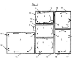
- the single figure shows schematically a ventilation system according to the invention in a building.
- the building consists of a corridor 1 with an entrance area 2 and from the hall 1 branches off other rooms. These are the bathroom 3, the kitchen 4, the living room 5 and two bedrooms 6 and 7.
- a ventilation device 8 is provided in the bathroom 3, which with not shown supply air and exhaust air ducts or the environment is connected.
- a first vent ring channel 9 is provided, which branches off via a not-shown feed-in distribution in or on the ventilation unit 8 in two directions, forming a closed ring.
- a connecting element 10 is provided in the wall connecting the bathroom 3 with the kitchen 4, which is formed for example of two T-shaped crizverteilerettin that form a going through this wall line.
- a further vent ring channel 11 is provided, which is also split from the connecting element 10, starting in two forming a closed ring sub-channels.
- the vent ring channel 11 is thus connected via the vent ring channel 9 with the ventilation unit 8 in flow communication.
- an air inlet 12 is indicated in the first vent ring channel 9 and the further vent ring channel 11, via which spent air can be sucked into the vent ring channels 9 and 11 and the ventilation unit 8 supplied.
- a first ventilation ring channel 13 is formed, which in turn is split by means of a feed distributor on or in the ventilation unit 8 into two sub-channels which define the ring channel.
- a connecting element 10 is provided, which connects the first ventilation ring channel 13 with a Verteilerringkanal 14, which is provided in the corridor 1.
- Verteilerringkanal 14 branch off in turn via further connecting elements 10 further ventilation ring channels 15, 16 and 17, which are provided in the living room 5, the bedroom 6 and the bedroom 7.
- the further ventilation ring channels 15, 16 and 17 are each with one or provided a plurality of outlets 18, via which fresh air can be discharged into the respective rooms.
- the line sections of these ventilation ring channels 15, 16, 17 can be made comparatively small in size.
- the total air volume flow for the ventilation of the rooms is conducted both via the distributor ring channel 14 and via the first ventilation ring channel 13.
- the channel elements of the first ventilation ring channel 13 and the distributor ring channel 14 are therefore expediently larger in size than the further ventilation ring channels 15, 16 and 17.
- the further venting ring channel 11 for the kitchen 4 can be made smaller than the first venting ring channel 9, which runs in the bathroom 3 and must absorb both the extracted from the bathroom 3 and 4 from the kitchen air.
- the design of the air ducts as ring channels is based on the idea according to the invention of dividing the total air volume flow into two air volume flows so as to achieve smaller pressure losses and smaller air duct cross sections.
- the air inlets and outlets can be designed for this purpose as separate components and expediently be docked to the ring channel system. This is usually done only downstream of the T-shaped control distribution elements, which are integrated into the ring channels and establish a connection between the individual ring channels.
- a main ring channel for example, the Verteilerringkanal 14 serve exclusively as an air distributor, so do not have an air inlet or air outlet at the same time.
- the distribution ring channel 14 is particularly efficient for air distribution because it is placed inside the building such that This any other area or space to be supplied can be supplied via the connecting elements 10 formed from the T-shaped control distribution elements.
Landscapes
- Engineering & Computer Science (AREA)
- Chemical & Material Sciences (AREA)
- Combustion & Propulsion (AREA)
- Mechanical Engineering (AREA)
- General Engineering & Computer Science (AREA)
- Building Environments (AREA)
- Duct Arrangements (AREA)
Priority Applications (1)
| Application Number | Priority Date | Filing Date | Title |
|---|---|---|---|
| PL09713974T PL2245377T3 (pl) | 2008-02-27 | 2009-01-07 | Budynek z systemem wentylacji i sposób wyposażenia istniejącego budynku do postaci takiego budynku |
Applications Claiming Priority (2)
| Application Number | Priority Date | Filing Date | Title |
|---|---|---|---|
| DE102008011348.4A DE102008011348B4 (de) | 2008-02-27 | 2008-02-27 | Lüftungssystem und Gebäude mit einem Lüftungssystem |
| PCT/EP2009/000020 WO2009106189A1 (de) | 2008-02-27 | 2009-01-07 | Lüftungssystem und verfahren zur ausrüstung eines gebäudes mit einem lüftungssystem |
Publications (2)
| Publication Number | Publication Date |
|---|---|
| EP2245377A1 EP2245377A1 (de) | 2010-11-03 |
| EP2245377B1 true EP2245377B1 (de) | 2019-05-29 |
Family
ID=39768385
Family Applications (1)
| Application Number | Title | Priority Date | Filing Date |
|---|---|---|---|
| EP09713974.5A Active EP2245377B1 (de) | 2008-02-27 | 2009-01-07 | Gebäudesystem mit einem lüftungssystem und verfahren zur umrüstung eines bestehenden gebäudes zu einem derartigen gebäude |
Country Status (6)
| Country | Link |
|---|---|
| EP (1) | EP2245377B1 (da) |
| DE (2) | DE102008011348B4 (da) |
| DK (1) | DK2245377T3 (da) |
| ES (1) | ES2743102T3 (da) |
| PL (1) | PL2245377T3 (da) |
| WO (1) | WO2009106189A1 (da) |
Families Citing this family (5)
| Publication number | Priority date | Publication date | Assignee | Title |
|---|---|---|---|---|
| DE202008006542U1 (de) | 2008-05-14 | 2008-11-06 | Pluggit International Sarl | System zur Befestigung einer Leitung |
| DE102009041610B4 (de) | 2009-09-17 | 2011-09-01 | Helios Ventilatoren Gmbh & Co. Kg | Luftführungssystem zur Belüftung von Räumen eines Gebäudes |
| DE202011102188U1 (de) | 2011-06-17 | 2012-09-18 | Stiebel Eltron Gmbh & Co. Kg | Lüftungssystem |
| DE102014103155A1 (de) | 2014-03-10 | 2015-09-10 | Pluggit Gmbh | Verfahren zur Raumlüftung und Lüftungssystem hierfür |
| DE102014106824A1 (de) | 2014-05-14 | 2015-11-19 | Fraunhofer-Gesellschaft zur Förderung der angewandten Forschung eingetragener Verein | Kompaktes Lüftungsgerät mit einzeln ansteuerbaren Luftfördereinheiten |
Family Cites Families (9)
| Publication number | Priority date | Publication date | Assignee | Title |
|---|---|---|---|---|
| US1732959A (en) | 1926-02-26 | 1929-10-22 | William E Watt | Ventilating system |
| US3303770A (en) | 1964-11-25 | 1967-02-14 | Joseph G Anthony | Building with internal air flow passages |
| FR2361511A1 (fr) | 1976-08-13 | 1978-03-10 | Mounier Francois | Perfectionnements apportes aux locaux chauffes ou refroidis |
| DE3113285A1 (de) | 1981-04-02 | 1982-10-21 | Schmidt Reuter Ingenieurgesellschaft mbH & Co KG, 5000 Köln | Heizungs- und lueftungsanlage |
| DE3802583A1 (de) * | 1988-01-29 | 1989-08-10 | Wetzel Alfred | Lueftungsvorrichtung fuer fenster und/oder fenstertueren zur rekuperativen be- und entlueftung von aufenthaltsraeumen |
| US5468184A (en) * | 1993-10-13 | 1995-11-21 | Collier; William R. | Air circulation system for enclosed structures |
| DE4343759A1 (de) | 1993-12-21 | 1995-06-22 | Wimboeck Besitz Gmbh | Lüftungsanordnung |
| DE9407150U1 (de) | 1994-04-29 | 1994-09-01 | Schmidt, Christoph, Dr., 35440 Linden | Anlage zur solaren Heizung und kontrollierten Lüftung von Gebäuden, insbesondere Reihenhäuser und Doppelhäusern, mit geringem Wärmebedarf |
| DE19517984C2 (de) | 1995-05-16 | 2001-08-30 | Herms Marc | Anordnung zur Bündelung von Versorgungsleitungen für ein Gebäude |
-
2008
- 2008-02-27 DE DE102008011348.4A patent/DE102008011348B4/de not_active Expired - Fee Related
- 2008-06-14 DE DE202008008005U patent/DE202008008005U1/de not_active Expired - Lifetime
-
2009
- 2009-01-07 ES ES09713974T patent/ES2743102T3/es active Active
- 2009-01-07 WO PCT/EP2009/000020 patent/WO2009106189A1/de not_active Ceased
- 2009-01-07 EP EP09713974.5A patent/EP2245377B1/de active Active
- 2009-01-07 PL PL09713974T patent/PL2245377T3/pl unknown
- 2009-01-07 DK DK09713974.5T patent/DK2245377T3/da active
Non-Patent Citations (1)
| Title |
|---|
| None * |
Also Published As
| Publication number | Publication date |
|---|---|
| DE202008008005U1 (de) | 2008-09-18 |
| WO2009106189A1 (de) | 2009-09-03 |
| DK2245377T3 (da) | 2019-08-19 |
| PL2245377T3 (pl) | 2019-11-29 |
| ES2743102T3 (es) | 2020-02-18 |
| DE102008011348B4 (de) | 2023-09-28 |
| EP2245377A1 (de) | 2010-11-03 |
| DE102008011348A1 (de) | 2009-09-03 |
Similar Documents
| Publication | Publication Date | Title |
|---|---|---|
| EP2479508B1 (de) | Luftverteilungssystem | |
| EP2245377B1 (de) | Gebäudesystem mit einem lüftungssystem und verfahren zur umrüstung eines bestehenden gebäudes zu einem derartigen gebäude | |
| EP2288854B1 (de) | T-förmiges abzweigstück, insbesondere für ein lüftungssystem | |
| EP2378216A2 (de) | Lüftungseinrichtung | |
| EP2288855B1 (de) | Luftauslass | |
| DE202007001429U1 (de) | Einrichtung zum Heizen, Kühlen und/oder Lüften eines Raumes eines Gebäudes | |
| CH701880A2 (de) | Luftführungssystem zur Belüftung von Räumen eines Gebäudes. | |
| EP2515048A2 (de) | Lüftungskasten | |
| EP2857772B1 (de) | Lüftungsgerät mit Wärmerückgewinnung | |
| EP3002173A1 (de) | Schienenfahrzeug mit einem dachklimakanal | |
| EP2161512B1 (de) | Dezentrales lufttechnisches Gerät sowie lufttechnische Anlage mit einem derartigen Gerät | |
| AT505746B1 (de) | Brandschutzanlage für gebäude | |
| DE10121366B4 (de) | Aufputz-Installationssystem für ein etagenweises Verlegen technischer Medien in Gebäuden | |
| DE202011110533U1 (de) | Luftverteilungssystem | |
| EP1582821B1 (de) | Luftführungssystem | |
| DE202009012543U1 (de) | Vorrichtung zum Verteilen von Zuluft und zum Sammeln von Abluft in einem Gebäude-Belüftungssystem | |
| DE102012003383A1 (de) | Multifunktionselement für Raumwandungen und Vorrichtung zur Beleuchtung und Klimatisierung von Räumen | |
| DE102012220391A1 (de) | System zur Belüftung eines Gebäudes | |
| EP0374527A2 (de) | Luftverteilsystem | |
| DE20113291U1 (de) | Nasszelle mit Klimatisierungsvorrichtung | |
| EP1947398B1 (de) | Einrichtung zum Heizen, Kühlen und/oder Lüften eines Raumes eines Gebäudes | |
| DE102006053355B4 (de) | Heiz- und Belüftungsvorrichtung | |
| DE202026100610U1 (de) | Lüftungsvorrichtung | |
| DE202011004573U1 (de) | Funktionselement für Raumwandungen | |
| DE202011110359U1 (de) | Luftverteilungssystem |
Legal Events
| Date | Code | Title | Description |
|---|---|---|---|
| PUAI | Public reference made under article 153(3) epc to a published international application that has entered the european phase |
Free format text: ORIGINAL CODE: 0009012 |
|
| 17P | Request for examination filed |
Effective date: 20100729 |
|
| AK | Designated contracting states |
Kind code of ref document: A1 Designated state(s): AT BE BG CH CY CZ DE DK EE ES FI FR GB GR HR HU IE IS IT LI LT LU LV MC MK MT NL NO PL PT RO SE SI SK TR |
|
| AX | Request for extension of the european patent |
Extension state: AL BA RS |
|
| DAX | Request for extension of the european patent (deleted) | ||
| RAP1 | Party data changed (applicant data changed or rights of an application transferred) |
Owner name: PLUGGIT GMBH |
|
| 17Q | First examination report despatched |
Effective date: 20160408 |
|
| STAA | Information on the status of an ep patent application or granted ep patent |
Free format text: STATUS: EXAMINATION IS IN PROGRESS |
|
| GRAP | Despatch of communication of intention to grant a patent |
Free format text: ORIGINAL CODE: EPIDOSNIGR1 |
|
| STAA | Information on the status of an ep patent application or granted ep patent |
Free format text: STATUS: GRANT OF PATENT IS INTENDED |
|
| INTG | Intention to grant announced |
Effective date: 20181220 |
|
| GRAS | Grant fee paid |
Free format text: ORIGINAL CODE: EPIDOSNIGR3 |
|
| GRAA | (expected) grant |
Free format text: ORIGINAL CODE: 0009210 |
|
| STAA | Information on the status of an ep patent application or granted ep patent |
Free format text: STATUS: THE PATENT HAS BEEN GRANTED |
|
| AK | Designated contracting states |
Kind code of ref document: B1 Designated state(s): AT BE BG CH CY CZ DE DK EE ES FI FR GB GR HR HU IE IS IT LI LT LU LV MC MK MT NL NO PL PT RO SE SI SK TR |
|
| REG | Reference to a national code |
Ref country code: GB Ref legal event code: FG4D Free format text: NOT ENGLISH |
|
| REG | Reference to a national code |
Ref country code: CH Ref legal event code: EP |
|
| REG | Reference to a national code |
Ref country code: DE Ref legal event code: R096 Ref document number: 502009015797 Country of ref document: DE |
|
| REG | Reference to a national code |
Ref country code: AT Ref legal event code: REF Ref document number: 1138491 Country of ref document: AT Kind code of ref document: T Effective date: 20190615 |
|
| REG | Reference to a national code |
Ref country code: IE Ref legal event code: FG4D Free format text: LANGUAGE OF EP DOCUMENT: GERMAN |
|
| REG | Reference to a national code |
Ref country code: DK Ref legal event code: T3 Effective date: 20190816 |
|
| REG | Reference to a national code |
Ref country code: NL Ref legal event code: FP |
|
| REG | Reference to a national code |
Ref country code: SE Ref legal event code: TRGR |
|
| REG | Reference to a national code |
Ref country code: LT Ref legal event code: MG4D |
|
| PG25 | Lapsed in a contracting state [announced via postgrant information from national office to epo] |
Ref country code: HR Free format text: LAPSE BECAUSE OF FAILURE TO SUBMIT A TRANSLATION OF THE DESCRIPTION OR TO PAY THE FEE WITHIN THE PRESCRIBED TIME-LIMIT Effective date: 20190529 Ref country code: PT Free format text: LAPSE BECAUSE OF FAILURE TO SUBMIT A TRANSLATION OF THE DESCRIPTION OR TO PAY THE FEE WITHIN THE PRESCRIBED TIME-LIMIT Effective date: 20190930 Ref country code: LT Free format text: LAPSE BECAUSE OF FAILURE TO SUBMIT A TRANSLATION OF THE DESCRIPTION OR TO PAY THE FEE WITHIN THE PRESCRIBED TIME-LIMIT Effective date: 20190529 Ref country code: FI Free format text: LAPSE BECAUSE OF FAILURE TO SUBMIT A TRANSLATION OF THE DESCRIPTION OR TO PAY THE FEE WITHIN THE PRESCRIBED TIME-LIMIT Effective date: 20190529 Ref country code: NO Free format text: LAPSE BECAUSE OF FAILURE TO SUBMIT A TRANSLATION OF THE DESCRIPTION OR TO PAY THE FEE WITHIN THE PRESCRIBED TIME-LIMIT Effective date: 20190829 |
|
| PG25 | Lapsed in a contracting state [announced via postgrant information from national office to epo] |
Ref country code: GR Free format text: LAPSE BECAUSE OF FAILURE TO SUBMIT A TRANSLATION OF THE DESCRIPTION OR TO PAY THE FEE WITHIN THE PRESCRIBED TIME-LIMIT Effective date: 20190830 Ref country code: BG Free format text: LAPSE BECAUSE OF FAILURE TO SUBMIT A TRANSLATION OF THE DESCRIPTION OR TO PAY THE FEE WITHIN THE PRESCRIBED TIME-LIMIT Effective date: 20190829 Ref country code: LV Free format text: LAPSE BECAUSE OF FAILURE TO SUBMIT A TRANSLATION OF THE DESCRIPTION OR TO PAY THE FEE WITHIN THE PRESCRIBED TIME-LIMIT Effective date: 20190529 |
|
| PG25 | Lapsed in a contracting state [announced via postgrant information from national office to epo] |
Ref country code: EE Free format text: LAPSE BECAUSE OF FAILURE TO SUBMIT A TRANSLATION OF THE DESCRIPTION OR TO PAY THE FEE WITHIN THE PRESCRIBED TIME-LIMIT Effective date: 20190529 Ref country code: RO Free format text: LAPSE BECAUSE OF FAILURE TO SUBMIT A TRANSLATION OF THE DESCRIPTION OR TO PAY THE FEE WITHIN THE PRESCRIBED TIME-LIMIT Effective date: 20190529 Ref country code: SK Free format text: LAPSE BECAUSE OF FAILURE TO SUBMIT A TRANSLATION OF THE DESCRIPTION OR TO PAY THE FEE WITHIN THE PRESCRIBED TIME-LIMIT Effective date: 20190529 |
|
| PGFP | Annual fee paid to national office [announced via postgrant information from national office to epo] |
Ref country code: CZ Payment date: 20191220 Year of fee payment: 12 |
|
| REG | Reference to a national code |
Ref country code: ES Ref legal event code: FG2A Ref document number: 2743102 Country of ref document: ES Kind code of ref document: T3 Effective date: 20200218 |
|
| PGFP | Annual fee paid to national office [announced via postgrant information from national office to epo] |
Ref country code: PL Payment date: 20191223 Year of fee payment: 12 |
|
| REG | Reference to a national code |
Ref country code: DE Ref legal event code: R097 Ref document number: 502009015797 Country of ref document: DE |
|
| PLBE | No opposition filed within time limit |
Free format text: ORIGINAL CODE: 0009261 |
|
| STAA | Information on the status of an ep patent application or granted ep patent |
Free format text: STATUS: NO OPPOSITION FILED WITHIN TIME LIMIT |
|
| PGFP | Annual fee paid to national office [announced via postgrant information from national office to epo] |
Ref country code: SE Payment date: 20200127 Year of fee payment: 12 Ref country code: DK Payment date: 20200123 Year of fee payment: 12 |
|
| 26N | No opposition filed |
Effective date: 20200303 |
|
| PG25 | Lapsed in a contracting state [announced via postgrant information from national office to epo] |
Ref country code: SI Free format text: LAPSE BECAUSE OF FAILURE TO SUBMIT A TRANSLATION OF THE DESCRIPTION OR TO PAY THE FEE WITHIN THE PRESCRIBED TIME-LIMIT Effective date: 20190529 |
|
| PGFP | Annual fee paid to national office [announced via postgrant information from national office to epo] |
Ref country code: LU Payment date: 20200127 Year of fee payment: 12 |
|
| PGFP | Annual fee paid to national office [announced via postgrant information from national office to epo] |
Ref country code: FR Payment date: 20200123 Year of fee payment: 12 |
|
| PG25 | Lapsed in a contracting state [announced via postgrant information from national office to epo] |
Ref country code: MC Free format text: LAPSE BECAUSE OF FAILURE TO SUBMIT A TRANSLATION OF THE DESCRIPTION OR TO PAY THE FEE WITHIN THE PRESCRIBED TIME-LIMIT Effective date: 20190529 |
|
| REG | Reference to a national code |
Ref country code: CH Ref legal event code: PL |
|
| GBPC | Gb: european patent ceased through non-payment of renewal fee |
Effective date: 20200107 |
|
| PG25 | Lapsed in a contracting state [announced via postgrant information from national office to epo] |
Ref country code: GB Free format text: LAPSE BECAUSE OF NON-PAYMENT OF DUE FEES Effective date: 20200107 |
|
| PG25 | Lapsed in a contracting state [announced via postgrant information from national office to epo] |
Ref country code: CH Free format text: LAPSE BECAUSE OF NON-PAYMENT OF DUE FEES Effective date: 20200131 Ref country code: LI Free format text: LAPSE BECAUSE OF NON-PAYMENT OF DUE FEES Effective date: 20200131 |
|
| PG25 | Lapsed in a contracting state [announced via postgrant information from national office to epo] |
Ref country code: IE Free format text: LAPSE BECAUSE OF NON-PAYMENT OF DUE FEES Effective date: 20200107 |
|
| PG25 | Lapsed in a contracting state [announced via postgrant information from national office to epo] |
Ref country code: CZ Free format text: LAPSE BECAUSE OF NON-PAYMENT OF DUE FEES Effective date: 20210107 |
|
| REG | Reference to a national code |
Ref country code: DK Ref legal event code: EBP Effective date: 20210131 |
|
| REG | Reference to a national code |
Ref country code: SE Ref legal event code: EUG |
|
| PG25 | Lapsed in a contracting state [announced via postgrant information from national office to epo] |
Ref country code: LU Free format text: LAPSE BECAUSE OF NON-PAYMENT OF DUE FEES Effective date: 20210107 |
|
| PG25 | Lapsed in a contracting state [announced via postgrant information from national office to epo] |
Ref country code: FR Free format text: LAPSE BECAUSE OF NON-PAYMENT OF DUE FEES Effective date: 20210131 |
|
| PG25 | Lapsed in a contracting state [announced via postgrant information from national office to epo] |
Ref country code: SE Free format text: LAPSE BECAUSE OF NON-PAYMENT OF DUE FEES Effective date: 20210108 |
|
| PG25 | Lapsed in a contracting state [announced via postgrant information from national office to epo] |
Ref country code: DK Free format text: LAPSE BECAUSE OF NON-PAYMENT OF DUE FEES Effective date: 20210131 |
|
| PG25 | Lapsed in a contracting state [announced via postgrant information from national office to epo] |
Ref country code: MT Free format text: LAPSE BECAUSE OF FAILURE TO SUBMIT A TRANSLATION OF THE DESCRIPTION OR TO PAY THE FEE WITHIN THE PRESCRIBED TIME-LIMIT Effective date: 20190529 Ref country code: CY Free format text: LAPSE BECAUSE OF FAILURE TO SUBMIT A TRANSLATION OF THE DESCRIPTION OR TO PAY THE FEE WITHIN THE PRESCRIBED TIME-LIMIT Effective date: 20190529 |
|
| PGFP | Annual fee paid to national office [announced via postgrant information from national office to epo] |
Ref country code: NL Payment date: 20220324 Year of fee payment: 14 |
|
| PG25 | Lapsed in a contracting state [announced via postgrant information from national office to epo] |
Ref country code: MK Free format text: LAPSE BECAUSE OF FAILURE TO SUBMIT A TRANSLATION OF THE DESCRIPTION OR TO PAY THE FEE WITHIN THE PRESCRIBED TIME-LIMIT Effective date: 20190529 Ref country code: IS Free format text: LAPSE BECAUSE OF FAILURE TO SUBMIT A TRANSLATION OF THE DESCRIPTION OR TO PAY THE FEE WITHIN THE PRESCRIBED TIME-LIMIT Effective date: 20190929 |
|
| PG25 | Lapsed in a contracting state [announced via postgrant information from national office to epo] |
Ref country code: PL Free format text: LAPSE BECAUSE OF NON-PAYMENT OF DUE FEES Effective date: 20210107 |
|
| PGFP | Annual fee paid to national office [announced via postgrant information from national office to epo] |
Ref country code: ES Payment date: 20230216 Year of fee payment: 15 |
|
| PGFP | Annual fee paid to national office [announced via postgrant information from national office to epo] |
Ref country code: IT Payment date: 20230131 Year of fee payment: 15 Ref country code: BE Payment date: 20230123 Year of fee payment: 15 |
|
| REG | Reference to a national code |
Ref country code: NL Ref legal event code: MM Effective date: 20230201 |
|
| PG25 | Lapsed in a contracting state [announced via postgrant information from national office to epo] |
Ref country code: NL Free format text: LAPSE BECAUSE OF NON-PAYMENT OF DUE FEES Effective date: 20230201 |
|
| PGFP | Annual fee paid to national office [announced via postgrant information from national office to epo] |
Ref country code: AT Payment date: 20240118 Year of fee payment: 16 |
|
| PGFP | Annual fee paid to national office [announced via postgrant information from national office to epo] |
Ref country code: DE Payment date: 20240125 Year of fee payment: 16 |
|
| PG25 | Lapsed in a contracting state [announced via postgrant information from national office to epo] |
Ref country code: TR Free format text: LAPSE BECAUSE OF NON-PAYMENT OF DUE FEES Effective date: 20200107 |
|
| PG25 | Lapsed in a contracting state [announced via postgrant information from national office to epo] |
Ref country code: BE Free format text: LAPSE BECAUSE OF NON-PAYMENT OF DUE FEES Effective date: 20240131 |
|
| PG25 | Lapsed in a contracting state [announced via postgrant information from national office to epo] |
Ref country code: BE Free format text: LAPSE BECAUSE OF NON-PAYMENT OF DUE FEES Effective date: 20240131 |
|
| REG | Reference to a national code |
Ref country code: BE Ref legal event code: MM Effective date: 20240131 |
|
| PG25 | Lapsed in a contracting state [announced via postgrant information from national office to epo] |
Ref country code: IT Free format text: LAPSE BECAUSE OF NON-PAYMENT OF DUE FEES Effective date: 20240107 |
|
| REG | Reference to a national code |
Ref country code: ES Ref legal event code: FD2A Effective date: 20250226 |
|
| PG25 | Lapsed in a contracting state [announced via postgrant information from national office to epo] |
Ref country code: ES Free format text: LAPSE BECAUSE OF NON-PAYMENT OF DUE FEES Effective date: 20240108 |
|
| REG | Reference to a national code |
Ref country code: DE Ref legal event code: R119 Ref document number: 502009015797 Country of ref document: DE |
|
| REG | Reference to a national code |
Ref country code: AT Ref legal event code: MM01 Ref document number: 1138491 Country of ref document: AT Kind code of ref document: T Effective date: 20250107 |
|
| PG25 | Lapsed in a contracting state [announced via postgrant information from national office to epo] |
Ref country code: DE Free format text: LAPSE BECAUSE OF NON-PAYMENT OF DUE FEES Effective date: 20250801 |
|
| PG25 | Lapsed in a contracting state [announced via postgrant information from national office to epo] |
Ref country code: AT Free format text: LAPSE BECAUSE OF NON-PAYMENT OF DUE FEES Effective date: 20250107 |