EP2245377B1 - Building with a ventilation system and method for upgrading an existing building to such a building - Google Patents
Building with a ventilation system and method for upgrading an existing building to such a building Download PDFInfo
- Publication number
- EP2245377B1 EP2245377B1 EP09713974.5A EP09713974A EP2245377B1 EP 2245377 B1 EP2245377 B1 EP 2245377B1 EP 09713974 A EP09713974 A EP 09713974A EP 2245377 B1 EP2245377 B1 EP 2245377B1
- Authority
- EP
- European Patent Office
- Prior art keywords
- ring channel
- channels
- air
- building
- rooms
- Prior art date
- Legal status (The legal status is an assumption and is not a legal conclusion. Google has not performed a legal analysis and makes no representation as to the accuracy of the status listed.)
- Active
Links
Images
Classifications
-
- F—MECHANICAL ENGINEERING; LIGHTING; HEATING; WEAPONS; BLASTING
- F24—HEATING; RANGES; VENTILATING
- F24F—AIR-CONDITIONING; AIR-HUMIDIFICATION; VENTILATION; USE OF AIR CURRENTS FOR SCREENING
- F24F7/00—Ventilation
- F24F7/04—Ventilation with ducting systems, e.g. by double walls; with natural circulation
- F24F7/06—Ventilation with ducting systems, e.g. by double walls; with natural circulation with forced air circulation, e.g. by fan positioning of a ventilator in or against a conduit
- F24F7/08—Ventilation with ducting systems, e.g. by double walls; with natural circulation with forced air circulation, e.g. by fan positioning of a ventilator in or against a conduit with separate ducts for supplied and exhausted air with provisions for reversal of the input and output systems
Definitions
- the invention relates to a building with a ventilation system with multiple channels for loading and / or venting rooms of a building.
- at least one first and one second air distribution point and at least one channel connecting them can be provided for supplying and / or discharging air in at least two rooms of a building in a supply space, while in a further space at least one second channel is provided, which is provided with the second air distribution point and possibly a further air distribution point is fluidly connected.
- the invention relates to a method for equipping a building with a ventilation system.
- Known distribution systems for fresh air in homes and dwellings are differentiated according to two different concepts: Either round tubes are used, which are laid in a suspended ceiling or in a wall cladding, or it can be used flat channels, which can be laid below a finished floor (screed). In this case, air distribution systems are used on a case by case basis, which also allow individual regulation of the individual air duct strands.
- a ventilation arrangement which has a arranged in the ceiling region of the respective space collection channel, which is provided over its entire length with a channel opening, in which separators, Verschbpsblenden or the like can be used detachably.
- a ventilation system which has spaces below the floor for ventilation and ventilation. These intermediate spaces are each connected to a plurality of air outlets or exhaust air inlets. Due to the multi-layered floor structure, this system is not suitable for retrofitting existing buildings. In addition, the space required by the multi-layer floor construction space requirement is perceived as disadvantageous.
- the DE 38 02 583 A1 describes a window or door frame with hollow chamber profiles, which are designed as the window or the door annular surrounding Zu Kunststoff- or exhaust air ducts. Due to the heat exchange between the supply air and the exhaust air, the frame as a convection recuperator should achieve a ventilation of a room.
- Object of the present invention is to develop a ventilation system of the type mentioned in such a way that it is suitable for retrofitting in old buildings with minimal space requirements and low installation costs.
- At least one of the channels, preferably a plurality of channels, of the ventilation system is designed as an annular channel with two partial flow channels connected in parallel with respect to flow. Since the volume flow required for the ventilation can be divided between the two parallel sub-channels of the annular channel, each of these sub-channels can be configured with a comparatively small cross-section, so that these lines (sub-channels) save space in the corner or edge, for example between Lay the wall and ceiling.
- a ventilation device connected in flow-connected manner with the at least one annular channel is provided in a supply space, which is connected to at least one supply air source and / or one exhaust air sink.
- a Verteilerringkanal is provided which has at least three air distribution points.
- (ring) channels preferably modularly constructed from closed pipes and corresponding fittings for plug connection, that is, without a over the entire length extending channel opening.
- At least one of the channels is designed as an annular channel, that between two air distribution points, that is, for example, between a ventilation device and a control distribution element or a connecting element, to be conveyed air stream can be divided into two partial streams, by two parallel connected sections of the annular channel areteurleitbar.
- the air flow to be conveyed through a duct is divided into two partial flows, conducted in these two partial flows, for example below the ceiling, and brought together again in the second air distribution point.
- annular channels are provided, which are each assigned to different rooms of a building. It is particularly preferred if in each of the rooms of the building to be vented or vented, at least one annular channel is arranged, which is in flow communication with one or more of the annular channels of the other rooms.
- a central space for example, the hallway or the corridor of a dwelling, be provided with an annular channel, which is designed as a Verteilerringkanal and has at least three air distribution points.
- fresh air can be forwarded, for example from a supply room via a ring channel in the Verteilerringkanal in the hallway or the like., From which are connected via further air distribution points ring channels in the adjoining the hallway rooms.
- a supply room is provided in which a ventilation unit is arranged with at least a supply air line and / or an exhaust air line is connected or communicates with the environment as fresh air source and Abluftsenke. This ventilation unit forms a first air distribution point.
- connection element for example a T-shaped control distribution element, may be provided for connecting two ring channels.
- the supply room in which the first annular channel is laid is expediently a wet room, such as the bathroom, the kitchen or a toilet.
- Ventilation system can also be air inlets or outlets, which can be integrated in the annular channels in order to remove used air from the rooms or to deliver fresh air into them.
- the ventilation system according to the invention is preferably modular and consists of a variety of plug-in elements or fittings, such as adapters, sheet and distributor or T-pieces. These elements and fittings can be integrated at a suitable location in the lines of the ring channels in order to make at the respectively optimal location a ventilation or vent.
- At least one annular channel for supplying fresh air from the ventilation unit and at least one further annular channel for discharging are provided by spent air in the ventilation unit.
- other rooms can be equipped with a ring channel for the supply of fresh air and a ring channel for the discharge of spent air.
- the channel dimensions are preferably coordinated so that in relation to the expected length of the respective annular channel and each Through the annular channel to conductive volume flow a total of the least possible air resistance arises.
- the air volume flow to be conducted through the first annular channel, which is directly connected to the ventilation device, is greater than or equal to the air volume flow in the downstream annular channels.
- This (total) air volume flow is divided at a Einspeiseverteil adopted the ventilation unit on two individual volume flows, which are distributed in each case in one of the two loop directions. This significantly reduces air resistance and air velocity in the respective air ducts.
- the dimensioning of the first annular channel can be reduced accordingly, which only allows the requirement of a visual assembly in the room or wall area.
- annular channels of other rooms are connected to the first annular channel, which is connected directly to the ventilation unit.
- the air volume flow to be distributed by these other annular channels is at most equal to the (total) air volume flow, which is passed through the first annular channel.
- Suitable profiles can be used, which may already be part of the pipe or the fittings according to a preferred embodiment of the invention. in this connection can be used for different designs of profiles from “stucco" to "modern".
- the ring channels can be fixed by means of special brackets in the ceiling edge area. These brackets are preferably also at the same time the attachment of a display panel, for example, based on an L-shaped screen profile for the Lucasringkanal itself or channel fittings or T-shaped control distribution elements.
- At least one annular channel is arranged running in an edge between a wall and the ceiling and / or an edge between a wall and the room floor.
- a connecting element which can be formed from second T-shaped control distribution elements, is designed as a passageway penetrating a wall between two adjacent spaces.
- the ventilation system according to the invention is particularly suitable for retrofitting in existing buildings, eg. As part of a refurbishment.
- the invention will be explained in more detail using an exemplary embodiment and with reference to the drawing.
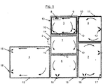
- the single figure shows schematically a ventilation system according to the invention in a building.
- the building consists of a corridor 1 with an entrance area 2 and from the hall 1 branches off other rooms. These are the bathroom 3, the kitchen 4, the living room 5 and two bedrooms 6 and 7.
- a ventilation device 8 is provided in the bathroom 3, which with not shown supply air and exhaust air ducts or the environment is connected.
- a first vent ring channel 9 is provided, which branches off via a not-shown feed-in distribution in or on the ventilation unit 8 in two directions, forming a closed ring.
- a connecting element 10 is provided in the wall connecting the bathroom 3 with the kitchen 4, which is formed for example of two T-shaped crizverteilerettin that form a going through this wall line.
- a further vent ring channel 11 is provided, which is also split from the connecting element 10, starting in two forming a closed ring sub-channels.
- the vent ring channel 11 is thus connected via the vent ring channel 9 with the ventilation unit 8 in flow communication.
- an air inlet 12 is indicated in the first vent ring channel 9 and the further vent ring channel 11, via which spent air can be sucked into the vent ring channels 9 and 11 and the ventilation unit 8 supplied.
- a first ventilation ring channel 13 is formed, which in turn is split by means of a feed distributor on or in the ventilation unit 8 into two sub-channels which define the ring channel.
- a connecting element 10 is provided, which connects the first ventilation ring channel 13 with a Verteilerringkanal 14, which is provided in the corridor 1.
- Verteilerringkanal 14 branch off in turn via further connecting elements 10 further ventilation ring channels 15, 16 and 17, which are provided in the living room 5, the bedroom 6 and the bedroom 7.
- the further ventilation ring channels 15, 16 and 17 are each with one or provided a plurality of outlets 18, via which fresh air can be discharged into the respective rooms.
- the line sections of these ventilation ring channels 15, 16, 17 can be made comparatively small in size.
- the total air volume flow for the ventilation of the rooms is conducted both via the distributor ring channel 14 and via the first ventilation ring channel 13.
- the channel elements of the first ventilation ring channel 13 and the distributor ring channel 14 are therefore expediently larger in size than the further ventilation ring channels 15, 16 and 17.
- the further venting ring channel 11 for the kitchen 4 can be made smaller than the first venting ring channel 9, which runs in the bathroom 3 and must absorb both the extracted from the bathroom 3 and 4 from the kitchen air.
- the design of the air ducts as ring channels is based on the idea according to the invention of dividing the total air volume flow into two air volume flows so as to achieve smaller pressure losses and smaller air duct cross sections.
- the air inlets and outlets can be designed for this purpose as separate components and expediently be docked to the ring channel system. This is usually done only downstream of the T-shaped control distribution elements, which are integrated into the ring channels and establish a connection between the individual ring channels.
- a main ring channel for example, the Verteilerringkanal 14 serve exclusively as an air distributor, so do not have an air inlet or air outlet at the same time.
- the distribution ring channel 14 is particularly efficient for air distribution because it is placed inside the building such that This any other area or space to be supplied can be supplied via the connecting elements 10 formed from the T-shaped control distribution elements.
Description
Die Erfindung betrifft ein Gebäude mit einem Lüftungssystem mit mehreren Kanälen zum Be- und/oder Entlüften von Räumen eines Gebäudes. Hierbei kann zur Zufuhr und/oder Ableitung von Luft in wenigstens zwei Räumen eines Gebäudes in einem Versorgungsraum wenigstens ein erster und ein zweiter Luftverteilungspunkt und wenigstens ein diese verbindender Kanal vorgesehen sein, während in einem weiteren Raum wenigstens ein zweiter Kanal vorgesehen ist, der mit dem zweiten Luftverteilungspunkt und gegebenenfalls einem weiteren Luftverteilungspunkt strömungsverbunden ist. Weiter betrifft die Erfindung ein Verfahren zur Ausrüstung eines Gebäudes mit einem Lüftungssystem.The invention relates to a building with a ventilation system with multiple channels for loading and / or venting rooms of a building. In this case, at least one first and one second air distribution point and at least one channel connecting them can be provided for supplying and / or discharging air in at least two rooms of a building in a supply space, while in a further space at least one second channel is provided, which is provided with the second air distribution point and possibly a further air distribution point is fluidly connected. Furthermore, the invention relates to a method for equipping a building with a ventilation system.
Bekannte Verteilsysteme für Frischluft in Wohnungen und Wohnhäusern werden nach zwei verschiedenen Konzepten unterschieden: Entweder werden hierzu Rundrohre verwendet, die in einer abgehängten Decke oder in einer Wandverkleidung verlegt sind, oder es werden Flachkanäle eingesetzt, die unterhalb eines Fertigfußbodens (Estrich) verlegt werden können. Dabei werden fallweise Luftverteilsysteme eingesetzt, die auch eine individuelle Regulierung der einzelnen Luftkanalstränge ermöglichen.Known distribution systems for fresh air in homes and dwellings are differentiated according to two different concepts: Either round tubes are used, which are laid in a suspended ceiling or in a wall cladding, or it can be used flat channels, which can be laid below a finished floor (screed). In this case, air distribution systems are used on a case by case basis, which also allow individual regulation of the individual air duct strands.
Für die Altbausanierung sind diese bekannten Konzepte jedoch aus verschiedenen Gründen entweder ungeeignet oder zumindest mit einem hohen Aufwand verbunden. So wird die sichtbare Verlegung derartiger Luftverteilsysteme in Wohnräumen optisch als störend empfunden. Weiter sprechen auch technische Gründe, wie der Raumbedarf derartiger Kanäle und/oder Verkleidungen gegen die Verwendung dieser bekannten Konzepte bei der Altbausanierung. Weiter ist die verdeckte Verlegung derartiger Kanäle durch Aufschlitzen von Wänden und Fußböden mit hohen Aufwand verbunden. Gleiches gilt für das Einziehen einer abgehängten Decke.However, for the renovation of old buildings, these known concepts are either unsuitable for various reasons or at least associated with a lot of effort. Thus, the visible installation of such Luftverteilsysteme in living spaces is visually distracting. Further speak also technical reasons, such as the space requirements of such channels and / or panels against the use of these known concepts in the renovation of old buildings. Next is the concealed installation of such channels by slitting walls and Floors associated with high effort. The same applies to the insertion of a suspended ceiling.
Aus der
In der
Aus der
Die
Aufgabe der vorliegenden Erfindung ist es, ein Lüftungssystem der eingangs genannten Art derart weiterzuentwickeln, dass es sich bei minimalen Platzbedarf und geringem Verlegeaufwand auch für die Nachrüstung in Altbauten geeignet ist.Object of the present invention is to develop a ventilation system of the type mentioned in such a way that it is suitable for retrofitting in old buildings with minimal space requirements and low installation costs.
Diese Aufgabe wird durch ein Gebäude nach Anspruch 1 sowie ein Verfahren nach Anspruch 11 gelöst. Erfindungsgemäß ist vorgesehen, dass wenigstens einer der Kanäle, vorzugsweise mehrere Kanäle, des Lüftungssystems (jeweils) als ein Ringkanal mit zwei strömungstechnisch parallel geschalteten Teilkanälen ausgebildet ist. Da der für die Be- und Entlüftung erforderliche Volumenstrom auf die beiden parallelen Teilkanäle des Ringkanals aufgeteilt werden kann, kann jeder dieser Teilkanäle mit einem vergleichsweise kleinen Querschnitt ausgestaltet sein, so dass sich diese Leitungen (Teilkanäle) platzsparend in der Ecke bzw. Kante beispielsweise zwischen Wand und Decke verlegen lassen. Die oben beschriebenen Nachteile der bekannten Systeme werden folglich mit dem erfindungsgemäßen Lüftungssystem vermieden. Gleichzeitig wird eine optimale Frischluftverteilung auf verschiedene Räume einer Wohnung oder einen Teil einer großen Wohnung im Geschosswohungsbau sichergestellt. Dabei ist es von besonderem Vorteil, dass die Montage aufgrund des geringen baulichen Aufwands auch im bewohnten Zustand ausgeführt werden kann, da die vergleichsweise kleinen Leitungen bzw. Teilkanäle nicht aufwendig in der Wand verlegt werden müssen. Weiter ist erfindungsgemäß in einem Versorgungsraum ein mit dem wenigstens einen Ringkanal strömungsverbundenes Lüftungsgerät vorgesehen, das mit wenigstens einer Zuluftquelle und/oder einer Abluftsenke verbunden ist. In einem zentralen Raum ist ein Verteilerringkanal vorgesehen, der wenigstens drei Luftverteilungspunkte aufweist.This object is achieved by a building according to
Im Gegensatz zu der aus der oben genannten
Nach einer besonders bevorzugten Ausführungsform der Erfindung ist wenigstens einer der Kanäle derart als ein Ringkanal ausgebildet, dass ein zwischen zwei Luftverteilungspunkten, das heißt beispielsweise zwischen einem Lüftungsgerät und einem Regelverteilerelement bzw. einem Verbindungselement, zu fördernder Luftstrom auf zwei Teilströme aufteilbar ist, die durch zwei parallel geschaltete Abschnitte des Ringkanals durchleitbar sind. Mit anderen Worten wird der durch einen Kanal zu fördernde Luftstrom in zwei Teilströme aufgeteilt, in diesen beiden Teilströmen beispielsweise unterhalb der Decke entlang geleitet und in dem zweiten Luftverteilungspunkt wieder zusammengeführt.According to a particularly preferred embodiment of the invention, at least one of the channels is designed as an annular channel, that between two air distribution points, that is, for example, between a ventilation device and a control distribution element or a connecting element, to be conveyed air stream can be divided into two partial streams, by two parallel connected sections of the annular channel are durchleitbar. In other words, the air flow to be conveyed through a duct is divided into two partial flows, conducted in these two partial flows, for example below the ceiling, and brought together again in the second air distribution point.
Es wird bevorzugt, wenn mehrere Ringkanäle vorgesehen sind, die jeweils verschiedenen Räumen eines Gebäudes zugeordnet sind. Dabei wird es besonders bevorzugt, wenn in jedem der Räume des Gebäudes, die zu be- oder entlüften sind, wenigstens ein Ringkanal angeordnet ist, der mit einem oder mehreren der Ringkanäle der übrigen Räume in Strömungsverbindung steht.It is preferred if a plurality of annular channels are provided, which are each assigned to different rooms of a building. It is particularly preferred if in each of the rooms of the building to be vented or vented, at least one annular channel is arranged, which is in flow communication with one or more of the annular channels of the other rooms.
Hierzu kann ein zentraler Raum, beispielsweise die Diele oder der Flur einer Wohnung, mit einem Ringkanal versehen sein, der als ein Verteilerringkanal ausgebildet ist und wenigstens drei Luftverteilungspunkte aufweist. So kann Frischluft beispielsweise aus einem Versorgungsraum über einen Ringkanal in den Verteilerringkanal in der Diele oder dgl. weitergeleitet werden, von welchem über weitere Luftverteilungspunkte Ringkanäle in den an die Diele angrenzenden Räumen angeschlossen werden. Um eine Wohnung oder ein Gebäude mit Frischluft zu versorgen und verbrauchte Luft abzuleiten, ist ein Versorgungsraum vorgesehen, in welchem ein Lüftungsgerät angeordnet ist, das mit wenigstens einer Zuluftleitung und/oder einer Abluftleitung verbunden ist bzw. mit der Umgebung als Frischluftquelle und Abluftsenke in Verbindung steht. Dieses Lüftungsgerät bildet dabei einen ersten Luftverteilungspunkt. Als ein zweiter Luftverteilungspunkt kann ein Verbindungselement, beispielsweise ein T-förmiges Regelverteilerelement, zur Verbindung zweier Ringkanäle vorgesehen sein. Der Versorgungsraum, in welchem der erste Ringkanal verlegt ist, ist zweckmäßigerweise ein Feuchtraum, wie beispielsweise das Bad, die Küche oder ein WC.For this purpose, a central space, for example, the hallway or the corridor of a dwelling, be provided with an annular channel, which is designed as a Verteilerringkanal and has at least three air distribution points. Thus, fresh air can be forwarded, for example from a supply room via a ring channel in the Verteilerringkanal in the hallway or the like., From which are connected via further air distribution points ring channels in the adjoining the hallway rooms. To supply an apartment or a building with fresh air and dissipate used air, a supply room is provided in which a ventilation unit is arranged with at least a supply air line and / or an exhaust air line is connected or communicates with the environment as fresh air source and Abluftsenke. This ventilation unit forms a first air distribution point. As a second air distribution point, a connection element, for example a T-shaped control distribution element, may be provided for connecting two ring channels. The supply room in which the first annular channel is laid, is expediently a wet room, such as the bathroom, the kitchen or a toilet.
Weitere Luftverteilungspunkte im Sinne der vorliegenden Erfindung können auch Luftein- oder -auslässe sein, die in die Ringkanäle integriert sein können, um verbrauchte Luft aus den Räumen abzuziehen bzw. Frischluft in diese abzugeben. Hierzu ist das erfindungsgemäße Lüftungssystem vorzugsweise modular aufgebaut und besteht aus einer Vielzahl von steckbaren Elementen oder Formstücken, wie Adaptern, Bogen- und Verteiler- oder T-Stücken. Diese Elemente und Formstücke sind an geeigneter Stelle in die Leitungen der Ringkanäle integrierbar, um an der jeweils optimalen Stelle eine Be- oder Entlüftung vornehmen zu können.Further air distribution points in the sense of the present invention can also be air inlets or outlets, which can be integrated in the annular channels in order to remove used air from the rooms or to deliver fresh air into them. For this purpose, the ventilation system according to the invention is preferably modular and consists of a variety of plug-in elements or fittings, such as adapters, sheet and distributor or T-pieces. These elements and fittings can be integrated at a suitable location in the lines of the ring channels in order to make at the respectively optimal location a ventilation or vent.
Um eine Entlüftung einiger Räume, beispielsweise der Feuchträume, und eine gleichzeitige Belüftung anderer Räume, beispielsweise Wohn- oder Schlafzimmern zu ermöglichen, wird es bevorzugt, wenn in dem Versorgungsraum wenigstens ein Ringkanal zur Zufuhr von Frischluft aus dem Lüftungsgerät und wenigstens ein weiterer Ringkanal zur Ableitung von verbrauchter Luft in das Lüftungsgerät vorgesehen sind. Abhängig von der Lage und Aufteilung der Räume des Gebäudes können auch weitere Räume mit jeweils einem Ringkanal für die Frischluftzufuhr und einem Ringkanal für die Ableitung von verbrauchter Luft ausgestattet werden.In order to allow venting of some rooms, such as the damp rooms, and a simultaneous ventilation of other rooms, such as living rooms or bedrooms, it is preferred if in the supply room at least one annular channel for supplying fresh air from the ventilation unit and at least one further annular channel for discharging are provided by spent air in the ventilation unit. Depending on the location and layout of the rooms of the building also other rooms can be equipped with a ring channel for the supply of fresh air and a ring channel for the discharge of spent air.
Die Kanaldimensionen werden vorzugsweise so aufeinander abgestimmt, dass in Bezug auf die zu erwartende Länge des jeweiligen Ringkanals und den jeweils durch den Ringkanal zu leitenden Volumenstrom ein insgesamt möglichst geringer Luftwiderstand entsteht. Der durch den ersten Ringkanal, der unmittelbar an das Lüftungsgerät angeschlossen ist, zu leitende Luftvolumenstrom ist dabei größer oder gleich dem Luftvolumenstrom in den nachgeschalteten Ringkanälen. Dieser (Gesamt-)Luftvolumenstrom wird an einem Einspeiseverteilstück des Lüftungsgeräts aufgeteilt auf zwei Einzelvolumenströme, die jeweils in eine der beiden Ringleitungsrichtungen verteilt werden. Dadurch verringern sich der Luftwiderstand und die Luftgeschwindigkeit in den jeweiligen Luftkanälen erheblich. Hierdurch kann die Dimensionierung des ersten Ringkanals entsprechend reduziert werden, was die Anforderung einer Sichtmontage im Raum- oder Wandbereich erst ermöglicht.The channel dimensions are preferably coordinated so that in relation to the expected length of the respective annular channel and each Through the annular channel to conductive volume flow a total of the least possible air resistance arises. The air volume flow to be conducted through the first annular channel, which is directly connected to the ventilation device, is greater than or equal to the air volume flow in the downstream annular channels. This (total) air volume flow is divided at a Einspeiseverteilstück the ventilation unit on two individual volume flows, which are distributed in each case in one of the two loop directions. This significantly reduces air resistance and air velocity in the respective air ducts. As a result, the dimensioning of the first annular channel can be reduced accordingly, which only allows the requirement of a visual assembly in the room or wall area.
Erfindungsgemäß sind an den ersten Ringkanal, der unmittelbar mit dem Lüftungsgerät verbunden ist, weitere Ringkanäle anderer Räume angeschlossen. Der durch diese anderen Ringkanäle zu verteilende Luftvolumenstrom ist dabei maximal gleich dem (Gesamt-)Luftvolumenstrom, der durch den ersten Ringkanal geleitet wird. Wenn mehrere Ringkanäle in Reihe hintereinander geschaltet sind, ist dabei vorzugsweise der Leitungsquerschnitt des dem Lüftungsgerät näherliegenden Ringkanals größer oder gleich dem Leitungsquerschnitt des mit diesem verbundenen, von dem Lüftungsgerät weiter entfernten Ringkanals. Hierdurch kann erreicht werden, dass nur in dem Versorgungsraum, beispielsweise dem WC, einem Badezimmer oder der Küche, dem zu verteilenden Gesamtluftvolumenstrom entsprechend geringfügig größere Leitungen verwendet werden, wobei in diesen Räumen ohnehin geringere optische Anforderungen gestellt werden, während in Wohnräumen nur vergleichsweise klein dimensionierte Kanäle eingesetzt werden müssen.According to the invention, further annular channels of other rooms are connected to the first annular channel, which is connected directly to the ventilation unit. The air volume flow to be distributed by these other annular channels is at most equal to the (total) air volume flow, which is passed through the first annular channel. When a plurality of ring channels are connected in series one behind the other, preferably the line cross section of the ring channel closer to the ventilation device is greater than or equal to the line cross section of the ring channel connected to it and further away from the ventilation device. As a result, it can be achieved that only slightly larger lines are used in the supply room, for example the toilet, a bathroom or the kitchen, the total air volume flow to be distributed, wherein in these rooms anyway lower optical requirements are placed, while in living rooms only comparatively small dimensions Channels must be used.
Zur Verkleidung der Rohrleitungen der Kanäle können passende Profile verwendet werden, die nach einer bevorzugten Ausführungsform der Erfindung schon Bestandteil der Rohrleitung bzw. der Formstücke sein können. Hierbei können verschiedenen Designs der Profile von "Stuck" bis "Modern" eingesetzt werden. Die Ringkanäle können mittels spezieller Halterungen im Deckenrandbereich befestigt werden. Diese Halterungen dienen vorzugsweise gleichzeitig auch der Befestigung einer Sichtverkleidung, zum Beispiel auf Basis eines L-förmigen Sichtblendprofils für den Luftringkanal selbst bzw. Kanalformstücke oder T-förmige Regelverteilerelemente.For covering the pipelines of the channels suitable profiles can be used, which may already be part of the pipe or the fittings according to a preferred embodiment of the invention. in this connection can be used for different designs of profiles from "stucco" to "modern". The ring channels can be fixed by means of special brackets in the ceiling edge area. These brackets are preferably also at the same time the attachment of a display panel, for example, based on an L-shaped screen profile for the Luftringkanal itself or channel fittings or T-shaped control distribution elements.
In einem erfindungsgemäßen Gebäude, in welchem mehrere Räume mit einem Lüftungssystem der oben genannten Art ausgestattet sind, ist wenigstens ein Ringkanal in einer Kante zwischen einer Wand und der Raumdecke und/oder einer Kante zwischen einer Wand und dem Raumboden verlaufend angeordnet. Ein Verbindungselement, welches aus zweit T-förmigen Regelverteilerelementen gebildet werden kann, ist dabei als ein eine Wand zwischen zwei benachbarten Räumen durchdringender Durchgangskanal ausgestaltet.In a building according to the invention, in which several rooms are equipped with a ventilation system of the type mentioned above, at least one annular channel is arranged running in an edge between a wall and the ceiling and / or an edge between a wall and the room floor. A connecting element, which can be formed from second T-shaped control distribution elements, is designed as a passageway penetrating a wall between two adjacent spaces.
Das erfindungsgemäße Lüftungssystem eignet sich insbesondere zur Nachrüstung in bestehenden Gebäuden, bspw. im Rahmen einer Altbausanierung.The ventilation system according to the invention is particularly suitable for retrofitting in existing buildings, eg. As part of a refurbishment.
Die Erfindung wird nachfolgend anhand eines Ausführungsbeispiels und unter Bezugnahme auf die Zeichnung näher erläutert. Die einzige Figur zeigt dabei schematisch ein erfindungsgemäßes Lüftungssystem in einem Gebäude.The invention will be explained in more detail using an exemplary embodiment and with reference to the drawing. The single figure shows schematically a ventilation system according to the invention in a building.
In der dargestellten Ausführungsform besteht das Gebäude aus einem Flur 1 mit einem Eingangsbereich 2 sowie von dem Flur 1 abzweigenden weiteren Räumen. Dies sind das Badezimmer 3, die Küche 4, das Wohnzimmer 5 sowie zwei Schlafzimmer 6 bzw. 7. Zur Be- und Entlüftung der Räume des Gebäudes ist in dem Badezimmer 3 ein Lüftungsgerät 8 vorgesehen, welches mit nicht dargestellten Zuluft- und Abluftleitungen bzw. der Umgebung verbunden ist.In the illustrated embodiment, the building consists of a
In dem Badezimmer 3 ist ein erster Entlüftungsringkanal 9 vorgesehen, der über ein nicht näher dargestelltes Einspeise-Verteilstück in oder an dem Lüftungsgerät 8 in zwei Richtungen abzweigt, die einen geschlossenen Ring bilden. Innerhalb des Entlüftungsringkanals 9 ist in der das Badezimmer 3 mit der Küche 4 verbindenden Wand ein Verbindungselement 10 vorgesehen, welches beispielsweise aus zwei T-förmigen Regelverteilerelementen gebildet ist, die eine durch diese Wand gehende Leitung bilden.In the
In der Küche 4 ist ein weiterer Entlüftungsringkanal 11 vorgesehen, welcher ebenfalls von dem Verbindungselement 10 ausgehend in zwei einen geschlossenen Ring bildende Teilkanäle aufgespalten wird. Der Entlüftungsringkanal 11 steht somit über den Entlüftungsringkanal 9 mit dem Lüftungsgerät 8 in Strömungsverbindung. Sowohl in dem Badezimmer 12 als auch in der Küche 4 ist in dem ersten Entlüftungsringkanal 9 bzw. dem weiteren Entlüftungsringkanal 11 jeweils ein Lufteinlass 12 angedeutet, über welchen verbrauchte Luft in die Entlüftungsringkanäle 9 bzw. 11 angesaugt und dem Lüftungsgerät 8 zugeführt werden kann.In the
In ähnlicher Weise ist in dem Badezimmer 3 ein erster Belüftungsringkanal 13 ausgebildet, welcher wiederum über ein Einspeise-Verteilstück an oder in dem Lüftungsgerät 8 in zwei Teilkanäle aufgespalten wird, welche den Ringkanal definieren. In der das Badezimmer 3 mit dem Flur 1 verbindende Wand ist ein Verbindungselement 10 vorgesehen, welches den ersten Belüftungsringkanal 13 mit einem Verteilerringkanal 14 verbindet, welcher in dem Flur 1 vorgesehen ist.Similarly, in the
Von dem Verteilerringkanal 14 zweigen wiederum über weitere Verbindungselemente 10 weitere Belüftungsringkanäle 15, 16 und 17 ab, die in dem Wohnzimmer 5, dem Schlafzimmer 6 bzw. dem Schlafzimmer 7 vorgesehen sind. Die weiteren Belüftungsringkanäle 15, 16 und 17 sind dabei jeweils mit einem oder mehreren Auslässen 18 versehen, über welche Frischluft in die jeweiligen Räume abgegeben werden kann.From the Verteilerringkanal 14 branch off in turn via further connecting
Da der Luftvolumenstrom, der über die weiteren Belüftungsringkanäle 15, 16 bzw. 17 abzugeben ist, vergleichweise gering ist, können die Leitungsabschnitte dieser Belüftungsringkanäle 15, 16, 17 vergleichweise klein dimensioniert ausgebildet sein. Dagegen wird sowohl über den Verteilerringkanal 14 als auch über den ersten Belüftungsringkanal 13 der Gesamtluftvolumenstrom für die Belüftung der Räume geleitet. Die Kanalelemente des ersten Belüftungsringkanals 13 und des Verteilerringkanals 14 sind daher zweckmäßigerweise größer dimensioniert als die weiteren Belüftungsringkanäle 15, 16 und 17.Since the air volume flow, which is to be delivered via the further
Entsprechend kann auch der weitere Entlüftungsringkanal 11 für die Küche 4 kleiner dimensioniert werden als der erste Entlüftungsringkanal 9, der in dem Badezimmer 3 verläuft und sowohl die aus dem Badezimmer 3 als auch die aus der Küche 4 abgesaugte Luft aufnehmen muss.Accordingly, the further
Die Ausgestaltung der Luftkanäle als Ringkanäle basiert auf der erfindungsgemäßen Idee, den Gesamtluftvolumenstrom auf zwei Luftvolumenströme aufzuteilen, um so zu kleineren Druckverlusten und kleineren Luftkanalquerschnitten zu kommen. Die Luftein- und -auslässe können hierzu als separate Komponenten gestaltet sein und zweckmäßigerweise an das Ringkanalsystem angedockt werden. Dies erfolgt in der Regel erst nachgeordnet zu den T-förmigen Regelverteilerelementen, welche in die Ringkanäle integriert sind und eine Verbindung zwischen den einzelnen Ringkanälen herstellen.The design of the air ducts as ring channels is based on the idea according to the invention of dividing the total air volume flow into two air volume flows so as to achieve smaller pressure losses and smaller air duct cross sections. The air inlets and outlets can be designed for this purpose as separate components and expediently be docked to the ring channel system. This is usually done only downstream of the T-shaped control distribution elements, which are integrated into the ring channels and establish a connection between the individual ring channels.
Hierbei kann ein Hauptringkanal, beispielsweise der Verteilerringkanal 14, ausschließlich als ein Luftverteiler dienen, also nicht gleichzeitig einen Lufteinlass oder Luftauslass aufweisen. Der Verteilerringkanal 14 ist für die Luftverteilung besonders effizient, da dieser innerhalb des Gebäudes so platziert ist, dass von diesem jeder andere zu versorgende Bereich oder Raum über die aus den T-förmigen Regelverteilerelementen gebildeten Verbindungselemente 10 versorgt werden kann.Here, a main ring channel, for example, the
- 1 Flur1 hallway
- 2 Eingangsbereich2 entrance area
- 3 Badezimmer3 bathrooms
- 4 Küche4 kitchen
- 5 Wohnzimmer5 living rooms
- 6 Schlafzimmer6 bedrooms
- 7 Schlafzimmer7 bedrooms
- 8 Lüftungsgerät8 ventilation unit
- 9 erster Entlüftungsringkanal9 first vent ring channel
- 10 Verbindungselement (T-förmige Regelverteilerelemente)10 connection element (T-shaped control distribution elements)
- 11 weiterer Entlüftungsringkanal11 further vent ring channel
- 12 Lufteinlass12 air intake
- 13 erster Belüftungsringkanal13 first ventilation ring channel
- 14 Verteilerringkanal14 distribution ring channel
- 15 weiterer Belüftungsringkanal15 more ventilation ring channel
- 16 weiterer Belüftungsringkanal16 more ventilation ring channel
- 17 weiterer Belüftungsringkanal17 more ventilation ring channel
- 18 Auslass18 outlet
Claims (11)
- A building with several rooms (1, 3, 4, 5, 6, 7) and with a ventilation system for aeration and venting of the rooms (1, 3, 4, 5, 6, 7), wherein the ventilation system comprises several flow linked channels (9, 11, 13, 14, 15, 16, 17) for aeration and venting of the rooms (1, 3, 4, 5, 6, 7), wherein at least one, particularly several, of the channels is a ring channel (13) formed with two fluidically connected parallel subchannels, whereby a ventilation device (8) is provided in a supply room (3) which is fluidically connected with the at least one ring channel (13) and which constitutes a first air distribution point and is connected to at least one supply air source and/or a exhaust air sink, and wherein a distributor ring channel (14) is provided in a central room, comprising at least three air distribution points (10), by which the distributor ring channel (14) is fluidically connected with channels (9, 11, 13, 15, 16, 17) for aeration and venting of the rooms (1, 3, 4, 5, 6, 7), and wherein in the supply room (3) as second air distribution point (10) a connection element (10) is provided for connecting the at least one ring channel (13) with the distributor ring channel (14).
- Building according to claim 1, wherein in the supply room (3) at least the first and the second air distribution point (8, 10 ,12, 18) and at least the ring channel (9, 13) connecting these are provided, characterized in that at least the ring channel (13) and/or the distribution ring channel (14) are constituted as a ring channel (13, 14) such that an air stream to be conveyed between two air distribution points (8, 10, 12, 18) can be separated in two sub-streams which can be passed through two parts of the ring channel (13, 14) arranged in parallel.
- Building according to claim 2, characterized in that the several ring channels (9, 11, 13, 14, 15, 16, 17) are each assigned to different rooms (1, 3, 4, 5, 6, 7) of a building.
- Building according to claim 1 or 3, characterized in that at least one of the ring channels is constituted as a distributor ring channel (14) comprising at least three air distribution points (10).
- Building according to any of the preceding claims, characterized in that at least one of the channels or ring channels (9, 11, 13, 14, 15, 16, 17) comprises at least one air inlet or outlet (12, 18) as air distribution point.
- Building according to any of the preceding claims characterized in that at least a ring channel (13) for the supply of and at least one ring channel (9) for the discharge of air is provided in at least one supply room (3).
- Building according to any of the preceding claims, characterized in that several ring channels (9, 11, 13, 14, 15, 16, 17) are subsequently arranged in series, wherein preferably the conduit cross-section of the ring channel lying next to the ventilation device (8) is larger or equal to the conduit cross-section of the connected ring channel (11, 15, 16, 17) lying further away from the ventilation device (8).
- Building according to any preceding claims, characterized in that at least one of the channels (9, 11, 13, 14, 15, 16, 17) is covered with a profiled element.
- Building according to any of the preceding claims, characterized in that at least one ring channel (9, 11, 13, 14, 15, 16, 17) runs in an edge between a wall and a ceiling of the room and/or in an edge between the wall and the floor of the room.
- Building according to claim 9, characterized in that at least one connection element (10) is constituted as a passage channel penetrating a wall between two adjacent rooms (1, 3, 4, 5, 6, 7).
- Method in particular for retrofitting a building to a building according to any of the claims 1 to 10, wherein at least in some of the rooms (1, 3, 4, 5, 6, 7) each of the at least one ring channel (9, 11, 13, 14, 15, 16, 17) is laid in an edge between a wall and the ceiling of the room and/or in an edge between a wall and the floor of the room and is directly or indirectly connected with the venting device (8).
Priority Applications (1)
| Application Number | Priority Date | Filing Date | Title |
|---|---|---|---|
| PL09713974T PL2245377T3 (en) | 2008-02-27 | 2009-01-07 | Building with a ventilation system and method for upgrading an existing building to such a building |
Applications Claiming Priority (2)
| Application Number | Priority Date | Filing Date | Title |
|---|---|---|---|
| DE102008011348.4A DE102008011348B4 (en) | 2008-02-27 | 2008-02-27 | Ventilation system and buildings with a ventilation system |
| PCT/EP2009/000020 WO2009106189A1 (en) | 2008-02-27 | 2009-01-07 | Ventilation system and method for equipping a building with a ventilation system |
Publications (2)
| Publication Number | Publication Date |
|---|---|
| EP2245377A1 EP2245377A1 (en) | 2010-11-03 |
| EP2245377B1 true EP2245377B1 (en) | 2019-05-29 |
Family
ID=39768385
Family Applications (1)
| Application Number | Title | Priority Date | Filing Date |
|---|---|---|---|
| EP09713974.5A Active EP2245377B1 (en) | 2008-02-27 | 2009-01-07 | Building with a ventilation system and method for upgrading an existing building to such a building |
Country Status (6)
| Country | Link |
|---|---|
| EP (1) | EP2245377B1 (en) |
| DE (2) | DE102008011348B4 (en) |
| DK (1) | DK2245377T3 (en) |
| ES (1) | ES2743102T3 (en) |
| PL (1) | PL2245377T3 (en) |
| WO (1) | WO2009106189A1 (en) |
Families Citing this family (5)
| Publication number | Priority date | Publication date | Assignee | Title |
|---|---|---|---|---|
| DE202008006542U1 (en) | 2008-05-14 | 2008-11-06 | Pluggit International Sarl | System for fixing a pipe |
| DE102009041610B4 (en) | 2009-09-17 | 2011-09-01 | Helios Ventilatoren Gmbh & Co. Kg | Air duct system for ventilation of rooms of a building |
| DE202011102188U1 (en) | 2011-06-17 | 2012-09-18 | Stiebel Eltron Gmbh & Co. Kg | ventilation system |
| DE102014103155A1 (en) | 2014-03-10 | 2015-09-10 | Pluggit Gmbh | Method for room ventilation and ventilation system therefor |
| DE102014106824A1 (en) | 2014-05-14 | 2015-11-19 | Fraunhofer-Gesellschaft zur Förderung der angewandten Forschung eingetragener Verein | Compact ventilation unit with individually controllable air handling units |
Family Cites Families (9)
| Publication number | Priority date | Publication date | Assignee | Title |
|---|---|---|---|---|
| US1732959A (en) | 1926-02-26 | 1929-10-22 | William E Watt | Ventilating system |
| US3303770A (en) | 1964-11-25 | 1967-02-14 | Joseph G Anthony | Building with internal air flow passages |
| FR2361511A1 (en) | 1976-08-13 | 1978-03-10 | Mounier Francois | Building air conditioning distribution system - has outer and inner casing enclosing one or two cavities in which air circulates |
| DE3113285A1 (en) | 1981-04-02 | 1982-10-21 | Schmidt Reuter Ingenieurgesellschaft mbH & Co KG, 5000 Köln | HEATING AND VENTILATION SYSTEM |
| DE3802583A1 (en) * | 1988-01-29 | 1989-08-10 | Wetzel Alfred | Ventilating apparatus for windows and/or French windows for the recuperative ventilating and venting of lounges (recreation rooms) |
| US5468184A (en) * | 1993-10-13 | 1995-11-21 | Collier; William R. | Air circulation system for enclosed structures |
| DE4343759A1 (en) | 1993-12-21 | 1995-06-22 | Wimboeck Besitz Gmbh | Ventilation fitting for rooms with damp or greasy atmosphere |
| DE9407150U1 (en) | 1994-04-29 | 1994-09-01 | Schmidt Christoph Dr | System for solar heating and controlled ventilation of buildings, especially row houses and semi-detached houses, with low heat requirements |
| DE19517984C2 (en) | 1995-05-16 | 2001-08-30 | Herms Marc | Arrangement for bundling supply lines for a building |
-
2008
- 2008-02-27 DE DE102008011348.4A patent/DE102008011348B4/en active Active
- 2008-06-14 DE DE202008008005U patent/DE202008008005U1/en not_active Expired - Lifetime
-
2009
- 2009-01-07 ES ES09713974T patent/ES2743102T3/en active Active
- 2009-01-07 PL PL09713974T patent/PL2245377T3/en unknown
- 2009-01-07 DK DK09713974.5T patent/DK2245377T3/en active
- 2009-01-07 WO PCT/EP2009/000020 patent/WO2009106189A1/en active Application Filing
- 2009-01-07 EP EP09713974.5A patent/EP2245377B1/en active Active
Non-Patent Citations (1)
| Title |
|---|
| None * |
Also Published As
| Publication number | Publication date |
|---|---|
| DE202008008005U1 (en) | 2008-09-18 |
| EP2245377A1 (en) | 2010-11-03 |
| DE102008011348B4 (en) | 2023-09-28 |
| PL2245377T3 (en) | 2019-11-29 |
| ES2743102T3 (en) | 2020-02-18 |
| DK2245377T3 (en) | 2019-08-19 |
| WO2009106189A1 (en) | 2009-09-03 |
| DE102008011348A1 (en) | 2009-09-03 |
Similar Documents
| Publication | Publication Date | Title |
|---|---|---|
| EP2245377B1 (en) | Building with a ventilation system and method for upgrading an existing building to such a building | |
| EP2479508B1 (en) | Air distribution system | |
| EP2288854B1 (en) | T-shaped branch part, particularly for a ventilation system | |
| EP2378216A2 (en) | Ventilation device | |
| EP2288855B1 (en) | Air outlet | |
| AT511366B1 (en) | VENTILATION BOX | |
| DE202007001429U1 (en) | Heating, cooling and/or ventilating device for rooms in building has ventilation device connected directly and/or indirectly to wall apertures | |
| EP1582821B1 (en) | Air transfer system | |
| EP3002173A1 (en) | Rail vehicle with a roof air conditioning channel | |
| EP2161512B1 (en) | Decentralised ventilation device and ventilation assembly with such a device | |
| AT505746B1 (en) | FIRE PROTECTION SYSTEM FOR BUILDINGS | |
| CH701880A2 (en) | Air guiding system for ventilating rooms of building, has channel elements comprising cut-away portion at front end surface, where portion is open at contact surfaces and accommodates fixing units when elements are axially pushed together | |
| DE10121366B4 (en) | Surface-mounted installation system for laying technical media on floors in buildings | |
| DE202009012543U1 (en) | Device for distributing supply air and collecting exhaust air in a building ventilation system | |
| DE202011110533U1 (en) | Air distribution system | |
| WO2014072489A1 (en) | System for ventilating a building | |
| DE102006053355B4 (en) | Heating and ventilation device | |
| EP1947398B1 (en) | Installation for heating, cooling and/or ventilating a room in a building | |
| EP2857772A1 (en) | Heat recovery ventilator | |
| EP0374527A2 (en) | Air distribution system | |
| DE202011004573U1 (en) | Functional element for room walls | |
| DE102012003383A1 (en) | Multifunctional element for arrangement in region of ceiling of building, has air duct and outlet openings which are arranged in multi-functional element main portion, and bulbs are located in main portion on two parallel straight lines | |
| EP2431679A2 (en) | System for air conditioning a room | |
| DE102011078934A1 (en) | Air distribution unit for use in air-providing arrangement, particularly for heating or cooling of living space in multi-party residential property, has fluid conduit, where fluid is tempered from remote location by air machine | |
| DE202008009228U1 (en) | Central ventilation device for the air conditioning of a room |
Legal Events
| Date | Code | Title | Description |
|---|---|---|---|
| PUAI | Public reference made under article 153(3) epc to a published international application that has entered the european phase |
Free format text: ORIGINAL CODE: 0009012 |
|
| 17P | Request for examination filed |
Effective date: 20100729 |
|
| AK | Designated contracting states |
Kind code of ref document: A1 Designated state(s): AT BE BG CH CY CZ DE DK EE ES FI FR GB GR HR HU IE IS IT LI LT LU LV MC MK MT NL NO PL PT RO SE SI SK TR |
|
| AX | Request for extension of the european patent |
Extension state: AL BA RS |
|
| DAX | Request for extension of the european patent (deleted) | ||
| RAP1 | Party data changed (applicant data changed or rights of an application transferred) |
Owner name: PLUGGIT GMBH |
|
| 17Q | First examination report despatched |
Effective date: 20160408 |
|
| STAA | Information on the status of an ep patent application or granted ep patent |
Free format text: STATUS: EXAMINATION IS IN PROGRESS |
|
| GRAP | Despatch of communication of intention to grant a patent |
Free format text: ORIGINAL CODE: EPIDOSNIGR1 |
|
| STAA | Information on the status of an ep patent application or granted ep patent |
Free format text: STATUS: GRANT OF PATENT IS INTENDED |
|
| INTG | Intention to grant announced |
Effective date: 20181220 |
|
| GRAS | Grant fee paid |
Free format text: ORIGINAL CODE: EPIDOSNIGR3 |
|
| GRAA | (expected) grant |
Free format text: ORIGINAL CODE: 0009210 |
|
| STAA | Information on the status of an ep patent application or granted ep patent |
Free format text: STATUS: THE PATENT HAS BEEN GRANTED |
|
| AK | Designated contracting states |
Kind code of ref document: B1 Designated state(s): AT BE BG CH CY CZ DE DK EE ES FI FR GB GR HR HU IE IS IT LI LT LU LV MC MK MT NL NO PL PT RO SE SI SK TR |
|
| REG | Reference to a national code |
Ref country code: GB Ref legal event code: FG4D Free format text: NOT ENGLISH |
|
| REG | Reference to a national code |
Ref country code: CH Ref legal event code: EP |
|
| REG | Reference to a national code |
Ref country code: DE Ref legal event code: R096 Ref document number: 502009015797 Country of ref document: DE |
|
| REG | Reference to a national code |
Ref country code: AT Ref legal event code: REF Ref document number: 1138491 Country of ref document: AT Kind code of ref document: T Effective date: 20190615 |
|
| REG | Reference to a national code |
Ref country code: IE Ref legal event code: FG4D Free format text: LANGUAGE OF EP DOCUMENT: GERMAN |
|
| REG | Reference to a national code |
Ref country code: DK Ref legal event code: T3 Effective date: 20190816 |
|
| REG | Reference to a national code |
Ref country code: NL Ref legal event code: FP |
|
| REG | Reference to a national code |
Ref country code: SE Ref legal event code: TRGR |
|
| REG | Reference to a national code |
Ref country code: LT Ref legal event code: MG4D |
|
| PG25 | Lapsed in a contracting state [announced via postgrant information from national office to epo] |
Ref country code: HR Free format text: LAPSE BECAUSE OF FAILURE TO SUBMIT A TRANSLATION OF THE DESCRIPTION OR TO PAY THE FEE WITHIN THE PRESCRIBED TIME-LIMIT Effective date: 20190529 Ref country code: PT Free format text: LAPSE BECAUSE OF FAILURE TO SUBMIT A TRANSLATION OF THE DESCRIPTION OR TO PAY THE FEE WITHIN THE PRESCRIBED TIME-LIMIT Effective date: 20190930 Ref country code: LT Free format text: LAPSE BECAUSE OF FAILURE TO SUBMIT A TRANSLATION OF THE DESCRIPTION OR TO PAY THE FEE WITHIN THE PRESCRIBED TIME-LIMIT Effective date: 20190529 Ref country code: FI Free format text: LAPSE BECAUSE OF FAILURE TO SUBMIT A TRANSLATION OF THE DESCRIPTION OR TO PAY THE FEE WITHIN THE PRESCRIBED TIME-LIMIT Effective date: 20190529 Ref country code: NO Free format text: LAPSE BECAUSE OF FAILURE TO SUBMIT A TRANSLATION OF THE DESCRIPTION OR TO PAY THE FEE WITHIN THE PRESCRIBED TIME-LIMIT Effective date: 20190829 |
|
| PG25 | Lapsed in a contracting state [announced via postgrant information from national office to epo] |
Ref country code: GR Free format text: LAPSE BECAUSE OF FAILURE TO SUBMIT A TRANSLATION OF THE DESCRIPTION OR TO PAY THE FEE WITHIN THE PRESCRIBED TIME-LIMIT Effective date: 20190830 Ref country code: BG Free format text: LAPSE BECAUSE OF FAILURE TO SUBMIT A TRANSLATION OF THE DESCRIPTION OR TO PAY THE FEE WITHIN THE PRESCRIBED TIME-LIMIT Effective date: 20190829 Ref country code: LV Free format text: LAPSE BECAUSE OF FAILURE TO SUBMIT A TRANSLATION OF THE DESCRIPTION OR TO PAY THE FEE WITHIN THE PRESCRIBED TIME-LIMIT Effective date: 20190529 |
|
| PG25 | Lapsed in a contracting state [announced via postgrant information from national office to epo] |
Ref country code: EE Free format text: LAPSE BECAUSE OF FAILURE TO SUBMIT A TRANSLATION OF THE DESCRIPTION OR TO PAY THE FEE WITHIN THE PRESCRIBED TIME-LIMIT Effective date: 20190529 Ref country code: RO Free format text: LAPSE BECAUSE OF FAILURE TO SUBMIT A TRANSLATION OF THE DESCRIPTION OR TO PAY THE FEE WITHIN THE PRESCRIBED TIME-LIMIT Effective date: 20190529 Ref country code: SK Free format text: LAPSE BECAUSE OF FAILURE TO SUBMIT A TRANSLATION OF THE DESCRIPTION OR TO PAY THE FEE WITHIN THE PRESCRIBED TIME-LIMIT Effective date: 20190529 |
|
| PGFP | Annual fee paid to national office [announced via postgrant information from national office to epo] |
Ref country code: CZ Payment date: 20191220 Year of fee payment: 12 |
|
| REG | Reference to a national code |
Ref country code: ES Ref legal event code: FG2A Ref document number: 2743102 Country of ref document: ES Kind code of ref document: T3 Effective date: 20200218 |
|
| PGFP | Annual fee paid to national office [announced via postgrant information from national office to epo] |
Ref country code: PL Payment date: 20191223 Year of fee payment: 12 |
|
| REG | Reference to a national code |
Ref country code: DE Ref legal event code: R097 Ref document number: 502009015797 Country of ref document: DE |
|
| PLBE | No opposition filed within time limit |
Free format text: ORIGINAL CODE: 0009261 |
|
| STAA | Information on the status of an ep patent application or granted ep patent |
Free format text: STATUS: NO OPPOSITION FILED WITHIN TIME LIMIT |
|
| PGFP | Annual fee paid to national office [announced via postgrant information from national office to epo] |
Ref country code: SE Payment date: 20200127 Year of fee payment: 12 Ref country code: DK Payment date: 20200123 Year of fee payment: 12 |
|
| 26N | No opposition filed |
Effective date: 20200303 |
|
| PG25 | Lapsed in a contracting state [announced via postgrant information from national office to epo] |
Ref country code: SI Free format text: LAPSE BECAUSE OF FAILURE TO SUBMIT A TRANSLATION OF THE DESCRIPTION OR TO PAY THE FEE WITHIN THE PRESCRIBED TIME-LIMIT Effective date: 20190529 |
|
| PGFP | Annual fee paid to national office [announced via postgrant information from national office to epo] |
Ref country code: LU Payment date: 20200127 Year of fee payment: 12 |
|
| PGFP | Annual fee paid to national office [announced via postgrant information from national office to epo] |
Ref country code: FR Payment date: 20200123 Year of fee payment: 12 |
|
| PG25 | Lapsed in a contracting state [announced via postgrant information from national office to epo] |
Ref country code: MC Free format text: LAPSE BECAUSE OF FAILURE TO SUBMIT A TRANSLATION OF THE DESCRIPTION OR TO PAY THE FEE WITHIN THE PRESCRIBED TIME-LIMIT Effective date: 20190529 |
|
| REG | Reference to a national code |
Ref country code: CH Ref legal event code: PL |
|
| GBPC | Gb: european patent ceased through non-payment of renewal fee |
Effective date: 20200107 |
|
| PG25 | Lapsed in a contracting state [announced via postgrant information from national office to epo] |
Ref country code: GB Free format text: LAPSE BECAUSE OF NON-PAYMENT OF DUE FEES Effective date: 20200107 |
|
| PG25 | Lapsed in a contracting state [announced via postgrant information from national office to epo] |
Ref country code: CH Free format text: LAPSE BECAUSE OF NON-PAYMENT OF DUE FEES Effective date: 20200131 Ref country code: LI Free format text: LAPSE BECAUSE OF NON-PAYMENT OF DUE FEES Effective date: 20200131 |
|
| PG25 | Lapsed in a contracting state [announced via postgrant information from national office to epo] |
Ref country code: IE Free format text: LAPSE BECAUSE OF NON-PAYMENT OF DUE FEES Effective date: 20200107 |
|
| PG25 | Lapsed in a contracting state [announced via postgrant information from national office to epo] |
Ref country code: CZ Free format text: LAPSE BECAUSE OF NON-PAYMENT OF DUE FEES Effective date: 20210107 |
|
| REG | Reference to a national code |
Ref country code: DK Ref legal event code: EBP Effective date: 20210131 |
|
| REG | Reference to a national code |
Ref country code: SE Ref legal event code: EUG |
|
| PG25 | Lapsed in a contracting state [announced via postgrant information from national office to epo] |
Ref country code: LU Free format text: LAPSE BECAUSE OF NON-PAYMENT OF DUE FEES Effective date: 20210107 |
|
| PG25 | Lapsed in a contracting state [announced via postgrant information from national office to epo] |
Ref country code: FR Free format text: LAPSE BECAUSE OF NON-PAYMENT OF DUE FEES Effective date: 20210131 |
|
| PG25 | Lapsed in a contracting state [announced via postgrant information from national office to epo] |
Ref country code: SE Free format text: LAPSE BECAUSE OF NON-PAYMENT OF DUE FEES Effective date: 20210108 |
|
| PG25 | Lapsed in a contracting state [announced via postgrant information from national office to epo] |
Ref country code: DK Free format text: LAPSE BECAUSE OF NON-PAYMENT OF DUE FEES Effective date: 20210131 |
|
| PG25 | Lapsed in a contracting state [announced via postgrant information from national office to epo] |
Ref country code: MT Free format text: LAPSE BECAUSE OF FAILURE TO SUBMIT A TRANSLATION OF THE DESCRIPTION OR TO PAY THE FEE WITHIN THE PRESCRIBED TIME-LIMIT Effective date: 20190529 Ref country code: CY Free format text: LAPSE BECAUSE OF FAILURE TO SUBMIT A TRANSLATION OF THE DESCRIPTION OR TO PAY THE FEE WITHIN THE PRESCRIBED TIME-LIMIT Effective date: 20190529 |
|
| PGFP | Annual fee paid to national office [announced via postgrant information from national office to epo] |
Ref country code: NL Payment date: 20220324 Year of fee payment: 14 |
|
| PG25 | Lapsed in a contracting state [announced via postgrant information from national office to epo] |
Ref country code: MK Free format text: LAPSE BECAUSE OF FAILURE TO SUBMIT A TRANSLATION OF THE DESCRIPTION OR TO PAY THE FEE WITHIN THE PRESCRIBED TIME-LIMIT Effective date: 20190529 Ref country code: IS Free format text: LAPSE BECAUSE OF FAILURE TO SUBMIT A TRANSLATION OF THE DESCRIPTION OR TO PAY THE FEE WITHIN THE PRESCRIBED TIME-LIMIT Effective date: 20190929 |
|
| PG25 | Lapsed in a contracting state [announced via postgrant information from national office to epo] |
Ref country code: PL Free format text: LAPSE BECAUSE OF NON-PAYMENT OF DUE FEES Effective date: 20210107 |
|
| PGFP | Annual fee paid to national office [announced via postgrant information from national office to epo] |
Ref country code: ES Payment date: 20230216 Year of fee payment: 15 Ref country code: AT Payment date: 20230118 Year of fee payment: 15 |
|
| PGFP | Annual fee paid to national office [announced via postgrant information from national office to epo] |
Ref country code: IT Payment date: 20230131 Year of fee payment: 15 Ref country code: DE Payment date: 20230130 Year of fee payment: 15 Ref country code: BE Payment date: 20230123 Year of fee payment: 15 |
|
| REG | Reference to a national code |
Ref country code: NL Ref legal event code: MM Effective date: 20230201 |
|
| PG25 | Lapsed in a contracting state [announced via postgrant information from national office to epo] |
Ref country code: NL Free format text: LAPSE BECAUSE OF NON-PAYMENT OF DUE FEES Effective date: 20230201 |