EP0374527A2 - Air distribution system - Google Patents
Air distribution system Download PDFInfo
- Publication number
- EP0374527A2 EP0374527A2 EP89121790A EP89121790A EP0374527A2 EP 0374527 A2 EP0374527 A2 EP 0374527A2 EP 89121790 A EP89121790 A EP 89121790A EP 89121790 A EP89121790 A EP 89121790A EP 0374527 A2 EP0374527 A2 EP 0374527A2
- Authority
- EP
- European Patent Office
- Prior art keywords
- air
- air distribution
- duct
- ceiling
- ventilation
- Prior art date
- Legal status (The legal status is an assumption and is not a legal conclusion. Google has not performed a legal analysis and makes no representation as to the accuracy of the status listed.)
- Withdrawn
Links
Images


Classifications
-
- F—MECHANICAL ENGINEERING; LIGHTING; HEATING; WEAPONS; BLASTING
- F24—HEATING; RANGES; VENTILATING
- F24F—AIR-CONDITIONING; AIR-HUMIDIFICATION; VENTILATION; USE OF AIR CURRENTS FOR SCREENING
- F24F13/00—Details common to, or for air-conditioning, air-humidification, ventilation or use of air currents for screening
- F24F13/02—Ducting arrangements
- F24F13/0236—Ducting arrangements with ducts including air distributors, e.g. air collecting boxes with at least three openings
-
- F—MECHANICAL ENGINEERING; LIGHTING; HEATING; WEAPONS; BLASTING
- F24—HEATING; RANGES; VENTILATING
- F24F—AIR-CONDITIONING; AIR-HUMIDIFICATION; VENTILATION; USE OF AIR CURRENTS FOR SCREENING
- F24F7/00—Ventilation
- F24F7/04—Ventilation with ducting systems, e.g. by double walls; with natural circulation
- F24F7/06—Ventilation with ducting systems, e.g. by double walls; with natural circulation with forced air circulation, e.g. by fan positioning of a ventilator in or against a conduit
Definitions
- the invention relates to an air distribution system with one or more air transport channels connected to a ventilation center and one or more air distribution channels provided with air passages, which are connected to one another via at least one flow connection; it also relates to a ventilation duct and a ventilation ceiling formed from it.
- supply air and exhaust air are routed through air ducts, the cross section of which is selected so that an air speed in the range between approximately 5 m / s and 8 m / s is achieved.
- the branches for the individual air outlets which consist of either fixed or flexible pipe sections, are connected to these air lines. It is entirely possible to insert the air outlets into the wall of the air duct even at suitable points (if necessary with short connecting pieces).
- these air outlets are provided with adjustable flaps or adjustable wings so that the emerging jet enters the room in the desired direction and the mixing section necessary for mixing the supply air into the room air, if necessary. by swirl until the zone of subsidence has subsided.
- each of the air outlets has one of the pressure drop and, if applicable, of the speed profile of the one in the air line flowing air a different admission pressure and different inflow conditions, so that the desired or necessary configuration of the jet must be set separately for each of the air outlets.
- the jet ventilation withdraws from a source ventilation.
- the separation of the air transport channels from the air distribution channels ensures that pressure drops due to the air transport can no longer affect the air distribution, since the air distribution channels are only connected to the air transport channels with a few overflow connections and in them the overflowing air flows to the passages without a substantial axial air movement takes place.
- the overflow connections are matched in terms of their number and their arrangement to the number and arrangement of the air outlets. This means that only a single overflow connection must exist in a line section with few air passages, while more overflow connections must be provided at locations with an increase in air passages, the number of overflow connections being kept lower overall can than the number of air outlets. It is only essential that - apart from the necessary inflow and equalization flows - axial flows in the air distribution duct are avoided, as a result of which a uniform pressure level is achieved over the entire length of the distribution duct.
- the overflow connections can be achieved with relatively short connecting lines if the air transport duct and the air distribution duct (s) are arranged separately from one another. This arrangement allows a very flexible construction of the ventilation system, since changes in the air distribution channels or changes in the air passages do not affect the air transport channels. If the air distribution duct and the air transport duct are arranged directly next to one another and they have a common partition, the overflow connections are formed by simple overflow openings. It is advantageous if the air transport duct is adjacent to two air distribution ducts, since this provides a particularly space-saving installation option. In the flow connection - be it a relatively short connecting line or an overflow opening - actuators and / or devices for air treatment such as air filters or heat exchangers can also be installed. This opens up the possibility of performing subsequent air treatments, for example with the aim of meeting the requirements of different ventilation zones.
- the narrow trapezoidal sides of the air transport ducts facing the ventilated room can be provided with the necessary lighting fixtures (or also with other building technology-related equipment - sprinklers or the like).
- the room-side ends of the air distribution ducts contain the air outlets. These can be of all shapes common in ventilation technology, from simple air distribution grilles to swirl diffusers, slot diffusers to outflow grilles that cover the entire outflow area of the air distribution duct.
- the grids can also be designed as optical grids and the lighting fixtures can be arranged in the depth of the air distribution channels.
- the ceiling formed from such trapezoidal channels joined together can have individual exhaust air channels connected between two groups of supply air fields, which advantageously, in the form of air distribution channels, form a trapezoid downward. If the lighting fixtures are arranged on the narrow sides of these trapezoids in this case, their heat loss is taken directly from the exhaust air and dissipated, which reduces the cooling load of the ventilated room.
- the arrangement of these exhaust air ducts between the supply air duct groups takes place in accordance with the flow, so that the flow of space can develop as required. Preferred locations are ceiling areas above apparatuses or devices with greater heat release.
- the static negative pressures which occur as a result of the (relatively) high flow velocity in the air transport ducts in relation to the room can be used to mix the conditioned supply air in a suitable manner with the aim of reducing the temperature difference between the supply air and the room air with the same heat load.
- a thermal aftertreatment, in particular ceiling cooling can also be carried out by providing the walls of the air ducts with heat exchangers, the ribs of which enlarge the exchanger surface and project into the air flow.
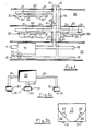
- FIG 1 is a schematic building section
- Darge provides with a supply floor (19) and with ventilated rooms (17) and a non-ventilated room (18).
- the air-conditioning center (10) is located on the supply floor (19) and communicates with the free atmosphere via the outside air supply line (11) and processes the outside air drawn in and presses it into the supply air supply lines (12).
- admixing of recirculated air can also take place, which is taken from the exhaust air discharge line (13) and fed to the mixing chamber of the air-conditioning center (10) via an air recirculation connector (14).
- Flaps (14.1) in the recirculating air connector (14) and in the exhaust air discharge line regulate the proportion of recirculating air.
- the excess air goes outside via the exhaust air duct (15).
- connecting lines branch off from the supply air supply line and from the exhaust air discharge line to the individual floors or parts of the floor, which are led into the relevant parts of the building via corresponding supply shafts (16) or supply ducts.
- the air transport channels (20) branch off from the rising supply air supply line (12) shown in FIG. 1 for the ventilated rooms (17).
- Air distribution channels are connected to the air transport channels via overflow connectors (21), which in turn are provided with air outlets (31).
- the arrangement of these air outlets (31) is adapted to the requirements in the ventilated rooms.
- the selection takes into account a uniform air distribution by uniform distribution of the air outlets (31) or a subdivision into ventilation zones, in that the air outlets (31) are combined in groups.
- the exhaust air is fed to the exhaust air discharge line via exhaust air collection channels (40) which are kept short here.
- the extraction of exhaust air from the floor shown here is intended to support and ensure the desired room air flow, with the inflow direction and exhaust air throughput being able to be changed within certain limits with the aid of the inflow grille (41). It goes without saying that the exhaust air extraction is also provided in other places can be according to the prevailing conditions in the ventilated room.
- FIG. 2 shows a section with a section of an air transport duct (20) to which three air distribution ducts (30) are connected.
- the connection is made via overflow connectors (21), which can be of a light or even flexible construction and thereby allow easy installation and also easy displacement of the air distribution channels (30).
- This is shown, for example, by the middle of the air distribution channels (30), which is shifted towards the left channel (for example, in order to actually achieve the desired room flow), the overflow connectors being slightly bent.
- the air outlets (31) - shown only as short sockets - can be arranged in various ways on the air distribution channels (30) to set up ventilation zones.
- the air outlets (31) on the left channel are provided approximately equally distributed, while in the middle channel they are combined in groups of three.
- the right channel has air outlet nozzles (31) of different lengths, so that the core area of the emerging jet can also be guided into the occupied zone, for example in order to achieve "spot cooling".
- FIG. 3 a) and b) show schematically the possible arrangements of air transport channel (20) and air distribution channels (30) to each other.
- three air distribution channels (30) are connected to an air transport channel (20) via overflow connectors (21).
- This has the advantage that the arrangement of the air outlets (31) on the air distribution channels (30) can be designed as desired and that the air distribution channels themselves can be shifted by simply changing (or deforming flexible) overflow connectors (21).
- FIG. 3 b) shows an air transport duct (20) on which the air distribution ducts (30) are integrally formed.
- the common walls are used as continuous dividers formed in which overflow openings (22) are provided according to the requirements (distribution of the air outlets (31) in the air distribution channels (30)).
- overflow openings can simultaneously be used for subsequent air treatment (heating, cooling, filtering); however, they can also contain overflow grids with the aid of which the flow resistance determining the overflow can be set.
- the latter means that only the axial air movement necessary for the inflow to the air outlets prevails in the air distribution channels, but a continuous axial air movement corresponding to a transport process is suppressed.
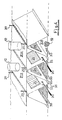
- FIG. 4 shows a further development of the embodiment according to FIG. 3 b), which is created by joining together a large number of individual channels shown there.
- a ventilation ceiling can be constructed in a surprisingly simple manner by assembling such individual ducts and designed as a suspended ventilation ceiling.
- Two side-by-side supply air transport channels (20) are supplied with the supply air via supply air supply lines (12), which flows (in the illustration on both sides) in the transport channels and via the overflow openings (22) provided with filter inserts (24) into the supply air transport channels (20) assigned supply air distribution channels (30) overflows.
- This ventilation ceiling can continue both in the longitudinal direction of the air transport and air distribution ducts, and can also be extended in any manner transversely to it.
- the supply air is cleaned in filter cells (24), it can also be used as a ventilation ceiling for production sensitive to dust, whereby it is irrelevant for the ventilation system whether the air outlets are swirl outlets (32) or outflow grids (33 ), provided with rectifiers (7) or rectifier fabrics. While turbulence-rich jet ventilation occurs in the first case, the second conducts Fall over to a source ventilation with low turbulence displacement flow.
- the upward-facing narrow sides of the trapezoids accommodate the suspension rods (29), so that the ventilation ceiling formed in this way can be used in a simple manner as a suspended ceiling.
- the downward-facing narrow sides of the trapezoids can be provided with corresponding lighting fixtures (26).
- FIG. 4 shows the use of an air filter which - since it has to be replaced from time to time - must expediently be accessible from the air distribution duct (30).
- the intermediate wall between the air distribution duct (30) and the air transport duct (20) has an overflow opening (22) into which the air filter cell (24) is inserted.
- the protruding edge (24.1) of the air filter cell with a circumferential seal is held by overlapping pressure strips (36), the upper of the pressure strips being fixed and the lower one being movable.
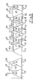
- FIG. 5 schematically shows a ventilation ceiling with supply air transport channels (20) which are supplied with supply air via the connected supply air supply lines (12) and which reaches the air transport channels (30) via the overflow openings (22).
- the underside of the transport channels is provided with the covers (30.1) into which swirl air outlets (32) are inserted.
- the ventilation zone formed in this way is flanked on both sides by exhaust air zones with exhaust air collecting ducts (40) connected to the exhaust air discharge lines (13).
- exhaust air collecting ducts (40) are in turn connected to trapezoidal ducts of the ceiling which are open at the bottom, so that the exhaust air flows out via these ducts without these ducts having essential guiding or distributing functions.
- the inflow of the exhaust air - represented by the small, upward-pointing arrows - is largely determined by the room flow, the arrangement of these exhaust air ducts over zones in which excess heat is released being advantageous.
- the lighting fixtures (26) are advantageously installed so that the exhaust air grid (43) also assumes the function of a light grid and can be designed according to the requirements of the light grid.
- the lighting fixtures (26) are provided in the supply air zones on the narrow sides of the supply air transport ducts (20) which are closed at the bottom. It goes without saying that if outflow grids are used instead of the swirl outlets, they can also be designed as light grids and the arrangement of the lighting fixtures can basically take place through the supply air distribution channels (30).
- the individual supply air distribution channels are suspended from the suspension rods (29), so that here again the shape of the suspended ceilings results, the supply air transport ducts (20) being closed by an upper cover (20.1) and the exhaust air collecting ducts (40) likewise being closed by an upper attachment.
- FIGS. 5 and 6 show the possibility of admixing room air in a simple manner into the supply air duct (20) - for example to reduce the temperature difference between room air and supply air - via an air mixing device (28) to the supply air supplied via the supply air supply line (12) , which is removed from the room air via an air outlet opening (28.1).
- the supply air premixed with room air in this way is then passed via the overflow opening (22) into the adjacent air distribution duct.
- the air distribution duct (30) (FIG. 7)
- the air flows in through the overflow opening (22) and, if there is a need, reaches an inserted cooling plate (25) with heat exchanger surfaces protruding into the air flow.
- This cooling plate (25) which is connected to a cooling supply via coolant connecting lines (25.1 and 25.2), can also serve as ceiling cooling in addition to air cooling. It goes without saying that the geometry of the supply air distribution duct must be adapted to these requirements. It goes without saying that such cooling (or heating) elements can be used in the area of the air transport channels. The supply air thus prepared then flows out via air outlets shown as swirl outlets (32).
Abstract
Description
Die Erfindung betrifft ein Luftverteilsystem mit einem oder mehreren mit einer Lüftungszentrale verbundenen Lufttransportkanal und einem oder mehreren mit Luftdurchlässen versehenen Luftverteilkanal, die über mindestens eine Strömungsverbindung miteinander verbunden sind; sie betrifft darüber hinaus einen Lüftungskanal sowie eine daraus gebildete Lüftungsdecke.The invention relates to an air distribution system with one or more air transport channels connected to a ventilation center and one or more air distribution channels provided with air passages, which are connected to one another via at least one flow connection; it also relates to a ventilation duct and a ventilation ceiling formed from it.
Bei der Belüftung von Gebäuden wird die in einer Lüftungszentrale aufbereitete Luft ggfs. über Verbindungskanäle, Lufttransportkanälen zugeführt, aus denen sie in Luftverteilkanäle eingespeist wird, die ihrerseits mit Luftdurchlässen ver sehen sind, aus denen die Luft in die zu belüftenden Räume einströmt. Diese, in der technischen Gebäudeausrüstung, bekannte Anlagentechnik hat aufgrund der strömungstechnischen Gegebenheiten den Nachteil, daß jeder Luftverteilkanal auch wesentliche Luftransportaufgaben zu erfüllen hat, muß doch in ihm die Luft auch bis zum letzten der Luftdurchlässe gefördert werden. Diese Lufttransportaufgabe bedingt unmittelbar einen Druckabfall längs des Luftverteilkanals, so daß jeder Luftdurchlaß auf einen anderen Vordruck eingestellt werden muß. Darüber hinaus müssen die Querschnitte, auch der Luftverteilkanäle, so gehalten sein, daß sie ihrer Transportaufgabe bei tolerierbarem Druckabfall nachkommen können. Letzteres führt zu einer Bauweise, die auf eine Überdimensionierung hinaus läuft, wenn nicht mit wiederum aufwendigen Übergangsstücken eine Querschnitt-Reduzierung des Luftverteilkanals zwischen Gruppen von Luftdurchtritten erreicht wird.When ventilating buildings, the air that is processed in a ventilation center is supplied via connecting ducts, air transport ducts, from which it is fed into air distribution ducts, which in turn ver with air passages are seen from which the air flows into the rooms to be ventilated. This, in the technical building equipment, known plant technology has the disadvantage due to the fluidic conditions that each air distribution duct also has to perform essential air transport tasks, since the air must be conveyed to the last of the air outlets in it. This air transport task directly results in a pressure drop along the air distribution channel, so that each air outlet must be set to a different admission pressure. In addition, the cross sections, including the air distribution channels, must be kept in such a way that they can fulfill their transport task with a tolerable pressure drop. The latter leads to a construction which amounts to overdimensioning if a cross-section reduction of the air distribution channel between groups of air passages is not achieved with again complex transition pieces.
Bei dem im allgemeinen verwendeten Lüftungssystemen werden Zuluft und Abluft durch Luftleitungen geführt, deren Querschnitt so gewählt wird, daß eine Luftgeschwindigkeit im Bereich zwischen etwa 5m/s und 8 m/s erreicht wird. An diese Luftleitungen sind die Abzweige für die einzelnen Luftdurchlässe angeschlossen, die entweder aus festen oder flexiblen Rohrleitungsstücken bestehen. Dabei ist es durchaus möglich, die Luftdurchlässe selbst an geeigneten Stellen in die Wand der Luftleitung einzufügen (ggfs. mit kurzen Stutzenansätzen). Diese Luftdurchlässe werden je nach den Erfordernissen der Strömung in den zu belüftenden Räumen mit einstellbaren Klappen oder einstellbaren Flügeln versehen, so daß der austretende Strahl in der gewünschten Richtung in den Raum eintritt und die für die Einmischung der Zuluft in die Raumluft notwendige Mischstrecke, ggfs. durch Drall, bis zum Erreichen der Aufenthaltszone abgeklungen ist. Dabei hat - wie schon ausgeführt - bei diesem Verteilsystem jeder der Luftdurchlässe eine vom Druckabfall und ggfs. vom Geschwindigkeitsprofil der in der Luftleitung strömenden Luft einen anderen Vordruck und andere Anströmverhältnisse, so daß die gewünschte oder notwendige Ausbildung des Strahles bei jedem der Luftdurchlässe gesondert eingestellt werden muß. Gleiches gilt auch, wenn die Strahllüftung gegenüber einer Quellüftung zurücktritt.In the ventilation systems generally used, supply air and exhaust air are routed through air ducts, the cross section of which is selected so that an air speed in the range between approximately 5 m / s and 8 m / s is achieved. The branches for the individual air outlets, which consist of either fixed or flexible pipe sections, are connected to these air lines. It is entirely possible to insert the air outlets into the wall of the air duct even at suitable points (if necessary with short connecting pieces). Depending on the flow requirements in the rooms to be ventilated, these air outlets are provided with adjustable flaps or adjustable wings so that the emerging jet enters the room in the desired direction and the mixing section necessary for mixing the supply air into the room air, if necessary. by swirl until the zone of subsidence has subsided. As already mentioned, with this distribution system each of the air outlets has one of the pressure drop and, if applicable, of the speed profile of the one in the air line flowing air a different admission pressure and different inflow conditions, so that the desired or necessary configuration of the jet must be set separately for each of the air outlets. The same also applies if the jet ventilation withdraws from a source ventilation.
Hier setzt die Erfindung ein, der die Aufgabe zugrunde liegt, das bekannte Lüftungssystem so weiterzubilden, daß die Überdimensionierung der Luftverteilkanäle vermieden und so der Anlagenbau wirtschaftlicher gestaltet werden kann, daß der Abgleich der Anlage vereinfacht und somit wirtschaftlicher gestaltet wird und daß vorabgeglichene Luft durch Dritte ohne wesentliches nachjustieren einsetzbar werden.This is where the invention comes in, which is based on the object of developing the known ventilation system in such a way that the overdimensioning of the air distribution ducts can be avoided and the plant construction can thus be designed more economically, that the adjustment of the plant is simplified and thus made more economical and that pre-balanced air can be provided by third parties can be used without significant readjustment.
Die Aufgabe wird nach der Erfindung gelöst durch das Kennzeich en des Anspruchs 1; Weiterbildungen beschreiben die Unteransprüche. Insbesondere wird ein Lüftungskanal und dessen Ausbildung zu einer Lüftungsdecke in den Kennzeichen der Ansprüche 7 bis 10 beschrieben.The object is achieved according to the invention by the characterizing part of
Durch die Trennung der Lufttransportkanäle von den Luftverteilkanälen wird erreicht, daß Druckabfälle infolge des Lufttransportes sich nicht auf die Luftverteilung mehr auswirken können, da die Luftverteilkanäle lediglich mit einigen Überströmverbindungen mit den Lufttransportkanälen verbunden sind und in ihnen die überströmende Luft zu den Durchlässen strömt, ohne daß eine wesentliche axiale Luftbewegung stattfindet. Es versteht sich dabei von selbst, daß die Überströmverbindungen in bezug auf ihre Anzahl und ihre Anordnung auf die Anzahl und Anordnung der Luftdurchlässe abgestimmt sind. Dies bedeutet, daß in einem Leitungsteil mit wenig Luftdurchlässen nur einzelne Überströmverbindungen bestehen müssen, während an Stellen mit einer Häufung von Luftdurchlässen auch mehr Überströmverbindungen vorgesehen werden müssen, wobei die Anzahl der Überströmverbindungen insgesamt geringer gehalten werden kann als die Anzahl der Luftdurchlässe. Wesentlich dabei ist lediglich, daß - abgesehen von notwendigen Zu- und Ausgleichsströmungen - axiale Strömungen im Luftverteilkanal vermieden werden, wodurch über die gesamte Länge des Verteilkanals hinweg ein einheitliches Druckniveau erreicht wird.The separation of the air transport channels from the air distribution channels ensures that pressure drops due to the air transport can no longer affect the air distribution, since the air distribution channels are only connected to the air transport channels with a few overflow connections and in them the overflowing air flows to the passages without a substantial axial air movement takes place. It goes without saying that the overflow connections are matched in terms of their number and their arrangement to the number and arrangement of the air outlets. This means that only a single overflow connection must exist in a line section with few air passages, while more overflow connections must be provided at locations with an increase in air passages, the number of overflow connections being kept lower overall can than the number of air outlets. It is only essential that - apart from the necessary inflow and equalization flows - axial flows in the air distribution duct are avoided, as a result of which a uniform pressure level is achieved over the entire length of the distribution duct.
Die Überströmverbindungen können dabei mit relativ kurzen Verbindungsleitungen erreicht werden, wenn Lufttransportkanal und der/die Luftverteilkanal/-kanäle voneinander getrennt angeordnet sind. Diese Anordnung gestattet einen sehr flexiblen Aufbau der Lüftungsanlage, da Veränderungen der Luftverteilkanäle oder Änderungen in den Luftdurchlässen die Lufttransportkanäle nicht betreffen. Sind Luftverteilkanal und Lufttransportkanal unmittelbar nebeneinander angeordnet und besitzen sie eine gemeinsame Zwischenwand, so werden die Überströmverbindungen durch einfache Überströmöffnungen gebildet. Vorteilhaft ist es dabei, wenn der Lufttransportkanal an zwei Luftverteilkanäle angrenzt, da dadurch eine besonders raumsparende Einbaumöglichkeit gegeben ist. In die Strömungsverbindung - sei es eine relativ kurze Verbindungleitung oder eine Überströmöffnung - lassen sich darüber hinaus Stellorgane und/oder Vorrichtungen zur Luftbehandlung wie Luftfilter oder Wärmetauscher einbauen. Dadurch eröffnet sich die Möglichkeit, nachträgliche Luftbehandlungen, etwa mit dem Ziel, Anforderungen unterschiedlicher Lüftungszonen nachzukommen, vorzunehmen.The overflow connections can be achieved with relatively short connecting lines if the air transport duct and the air distribution duct (s) are arranged separately from one another. This arrangement allows a very flexible construction of the ventilation system, since changes in the air distribution channels or changes in the air passages do not affect the air transport channels. If the air distribution duct and the air transport duct are arranged directly next to one another and they have a common partition, the overflow connections are formed by simple overflow openings. It is advantageous if the air transport duct is adjacent to two air distribution ducts, since this provides a particularly space-saving installation option. In the flow connection - be it a relatively short connecting line or an overflow opening - actuators and / or devices for air treatment such as air filters or heat exchangers can also be installed. This opens up the possibility of performing subsequent air treatments, for example with the aim of meeting the requirements of different ventilation zones.
Eine weitere Möglichkeit ergibt sich, wenn die Lufttransportkanäle und die Luftverteilkanäle mit gemeinsamer Zwischenwand nebeneinander aufgebaut werden, dadurch, daß eine Mehrzahl derartiger Kombinationen nebeneinander zu einer Lüftungsdecke ausgebildet wird. Dies erfolgt zweckmäßigerweise dadurch, daß in Längsrichtung durchgehende schräg gestellte Zwischenbleche längs verlaufende Kanäle bilden mit trapezförmigem Querschnitt, die abwechselnd nach oben oder nach unten weit sind. Die nach oben weiten Kanäle bilden dabei im Regelfall die Lufttransport kanäle, die nach unten weiten im Regelfall die Luftverteilkanäle. In den schrägen Zwischenwänden befinden sich dann die beide Kanalarten verbindenden Überströmöffnungen, durch die die aufbereitete Zuluft aus den Transportkanälen in die Verteilkanäle gelangt, um von diesen in die belüfteten Räume auszuströmen. Die dem belüfteten Raum zugewandten schmalen Trapezseiten der Lufttransportkanäle können mit den notwendigen Beleuchtungskörpern (oder auch mit anderen gebäudetechnisch notwendigen Einrichtungen - Sprinkler o. dgl.) versehen sein. Die raumseitigen Abschlüsse der Luftverteilkanäle enthalten die Luftdurchlässe. Diese können alle in der Raumlufttechnik üblichen Formen haben, vom einfachen Luftverteil-Gitter über Drall-Durchlässe, Schlitz-Durchlässe bis hin zu Ausström-Gittern, die die gesamte Ausström-Fläche des Luftverteilkanals überdecken. In diesem Falle können die Gitter auch als optische Gitter ausgebildet und die Beleuchtungskörper in der Tiefe der Luftverteilkanäle angeordnet sein.A further possibility arises if the air transport ducts and the air distribution ducts are constructed next to one another with a common partition wall, in that a plurality of such combinations is formed side by side to form a ventilation ceiling. This is expediently carried out by the fact that in the longitudinal direction continuous inclined intermediate plates form longitudinal channels with a trapezoidal cross section, which are alternately wide upwards or downwards. The channels, which are wide at the top, usually form the air transport ducts that usually widen the air distribution ducts downwards. In the sloping partitions there are the overflow openings connecting the two types of ducts, through which the treated supply air from the transport ducts reaches the distribution ducts in order to flow out into the ventilated rooms. The narrow trapezoidal sides of the air transport ducts facing the ventilated room can be provided with the necessary lighting fixtures (or also with other building technology-related equipment - sprinklers or the like). The room-side ends of the air distribution ducts contain the air outlets. These can be of all shapes common in ventilation technology, from simple air distribution grilles to swirl diffusers, slot diffusers to outflow grilles that cover the entire outflow area of the air distribution duct. In this case, the grids can also be designed as optical grids and the lighting fixtures can be arranged in the depth of the air distribution channels.
Die aus derartigen, aneinandergefügten trapezförmigen Kanälen gebildete Decke kann dabei einzelne, zwischen zwei Gruppen von Zuluftfeldern geschaltete, Abluftkanäle aufweisen, die vorteilhaft,in der Form von Luftverteilkanälen ausgebildet, ein nach unten weites Trapez bilden. Werden in diesem Fall die Beleuchtungskörper an den Schmalseiten dieser Trapeze angeordnet, wird deren Verlustwärme direkt von der Abluft übernommen und mit abgeführt, was die Kühllast des belüfteten Raumes verkleinert. Die Anordnung dieser Abluftkanäle zwischen den Zuluft kanal-Gruppen erfolgt dabei strömungsgerecht, so daß die Raumströmung sich den Erfordernissen entsprechend ausbilden kann. Bevorzugte Lagen dabei sind Deckenstellen über Apparaten oder Geräten mit größerer Wärme-Freisetzung.The ceiling formed from such trapezoidal channels joined together can have individual exhaust air channels connected between two groups of supply air fields, which advantageously, in the form of air distribution channels, form a trapezoid downward. If the lighting fixtures are arranged on the narrow sides of these trapezoids in this case, their heat loss is taken directly from the exhaust air and dissipated, which reduces the cooling load of the ventilated room. The arrangement of these exhaust air ducts between the supply air duct groups takes place in accordance with the flow, so that the flow of space can develop as required. Preferred locations are ceiling areas above apparatuses or devices with greater heat release.
Es versteht sich von selbst, daß die infolge der (relativ) hohen Strömungsgeschwindigkeit in den Lufttransportkanälen auftretenden statischen Unterdrücke gegenüber dem Raum ausge nutzt werden können, um der aufbereiteten Zuluft in geeigneter Weise Raumluft beizumischen mit dem Ziel, bei gleicher Wärmelast die Temperaturdifferenz der Zuluft gegenüber der Raumluft zu senken. In gleicher Weise kann auch eine thermische Nachbehandlung, insbesondere eine Deckenkühlung,durchgeführt werden, indem die Wände der Luftkanäle mit Wärmetauschern versehen werden, deren die Tauscherfläche vergrößernden Rippen in die Luftströmung hineinragen. Durch diese Ausbildung ist es möglich, mit dem so geschaffenen Lüftungssystem im Anlagenbau flexibel zum einen die Anforderungen bei der Projektierung erfüllen zu können, zum anderen aber auch nachträgliche Änderungen oder übermäßigen Aufwand berücksichtigen, ja sogar nach Fertigstellung noch im Wege des Umbaus vollziehen zu können. Dieser Vorteil beruht darauf, daß derartige Eingriffe lediglich die Luftverteilkanäle berühren und nicht die Lufttransportkanäle. Der Anwendungsbereich überspannt dabei den gesamten Bogen von einfachen Belüftungsaufgaben bis hin zur Komfort-Klimatisierung.It goes without saying that the static negative pressures which occur as a result of the (relatively) high flow velocity in the air transport ducts in relation to the room can be used to mix the conditioned supply air in a suitable manner with the aim of reducing the temperature difference between the supply air and the room air with the same heat load. In the same way, a thermal aftertreatment, in particular ceiling cooling, can also be carried out by providing the walls of the air ducts with heat exchangers, the ribs of which enlarge the exchanger surface and project into the air flow. With this training, it is possible to use the ventilation system created in this way in plant construction to be able to flexibly meet the requirements during project planning, but also to be able to take account of subsequent changes or excessive effort, even after completion, even by way of conversion. This advantage is based on the fact that such interventions only touch the air distribution channels and not the air transport channels. The application area spans the entire range from simple ventilation tasks to comfort air conditioning.
Das Wesen der Erfindung wird anhand der in den Figuren 1 bis 8 dargestellten Ausführungsbeispielen näher erläutert; dabei zeigen
- -
Figur 1 den Aufbau einer Lüftungsanlage (schematisch) - - Figur 2 Einzelheit Anschluß Luftverteilkanäle an Lufttransportkanal
- -
Figur 3 Darstellung nach Figur 2 schematisch
a): getrennte Verteilkanäle
b): integrierte Verteilkanäle - - Figur 4 Lüftungs-Doppeldecke
- - Figur 5 Filtereinsatz
- - Figur 6 Lüftungs-Doppeldecke mit Zu- und Abluftzonen
- - Figur 7 Zulufteinmischung in Lufttransportkanal
- - Figur 8 Deckenkühlung in Luftverteilkanal.
- - Figure 1 shows the structure of a ventilation system (schematic)
- - Figure 2 detail connection air distribution channels to air transport channel
- - Figure 3 representation according to Figure 2 schematically
a): separate distribution channels
b): integrated distribution channels - - Figure 4 Ventilation double ceiling
- - Figure 5 filter insert
- - Figure 6 Ventilation double ceiling with supply and exhaust air zones
- - Figure 7 Air intake in the air transport duct
- - Figure 8 ceiling cooling in the air distribution duct.
In der Figur 1 ist ein schematischer Gebäudeschnitt darge stellt mit einem Versorgungsgeschoß (19) sowie mit belüfteten Räumen (17) und einem unbelüfteten Raum (18). Im Versorgungsgeschoß (19) ist die Klimazentrale (10) untergebracht, die über die Außenluftzuleitung (11) mit der freien Atmosphäre in Verbindung steht und die dadurch angesaugte Außenluft aufbereitet und in die Zuluft-Zuführungsleitungen (12) drückt. In der Klimazentrale (10) kann auch ein Beimischen von Umluft stattfinden, die der Abluft-Abführungsleitung (13) entnommen und über einen Umluftverbinder (14) der Mischkammer der Klimazentrale (10) zugeführt wird. Klappen (14.1) im Umluftverbinder (14) sowie in der Abluft-Abführungsleitung regeln den Anteil der Umluft. Der Luftüberschuß geht über die Fortluftleitung (15) ins Freie. Von der Zuluft-Zuführungsleitung und von der Abluft-Abführungsleitung zweigen entsprechend der Gebäudestruktur Verbindungsleitungen zu den einzelnen Geschossen oder den Geschoßteilen ab,die über entsprechende Versorgungsschächte (16) oder Versorgungskanäle in die betreffenden Gebäudeteile geführt werden. Von der in der Figur 1 dargestellten aufsteigenden Zuluft-Zuführungsleitung (12) zweigen für die belüfteten Räume (17) die Lufttransportkanäle (20) ab. An die Lufttransportkanäle sind über Überströmverbinder (21) Luftverteilkanäle angeschlossen,die ihrerseits mit Luftauslässen (31) versehen sind. Die Anordnung dieser Luftauslässe (31) wird dabei den Erfordernissen in den belüfteten Räumen angepaßt. Die Auswahl berücksichtigt dabei eine gleichmäßige Luftverteilung durch gleichmäßige Verteilung der Luftauslässe (31) oder eine Unterteilung in Lüftungszonen, dadurch daß die Luftauslässe (31) gruppenweise zusammengefaßt werden. Die Abluft wird über hier kurz gehaltene Abluftsammelkanäle (40) der Abluft-Abführungsleitung zugeführt. Die hier dargestellte bodennahme Abluftentnahme soll die gewünschte Raumluftströmung unterstützen und sicherstellen, wobei Einströmrichtung und Abluftdurchsatz mit Hilfe der Einströmgitter (41) in gewissen Grenzen verändert werden kann. Es versteht sich von selbst, daß die Abluftentnahme auch an anderen Stellen vorgesehen werden kann entsprechend den im belüfteten Raum herrschenden Verhältnissen.In Figure 1 is a schematic building section Darge provides with a supply floor (19) and with ventilated rooms (17) and a non-ventilated room (18). The air-conditioning center (10) is located on the supply floor (19) and communicates with the free atmosphere via the outside air supply line (11) and processes the outside air drawn in and presses it into the supply air supply lines (12). In the air-conditioning center (10), admixing of recirculated air can also take place, which is taken from the exhaust air discharge line (13) and fed to the mixing chamber of the air-conditioning center (10) via an air recirculation connector (14). Flaps (14.1) in the recirculating air connector (14) and in the exhaust air discharge line regulate the proportion of recirculating air. The excess air goes outside via the exhaust air duct (15). Depending on the building structure, connecting lines branch off from the supply air supply line and from the exhaust air discharge line to the individual floors or parts of the floor, which are led into the relevant parts of the building via corresponding supply shafts (16) or supply ducts. The air transport channels (20) branch off from the rising supply air supply line (12) shown in FIG. 1 for the ventilated rooms (17). Air distribution channels are connected to the air transport channels via overflow connectors (21), which in turn are provided with air outlets (31). The arrangement of these air outlets (31) is adapted to the requirements in the ventilated rooms. The selection takes into account a uniform air distribution by uniform distribution of the air outlets (31) or a subdivision into ventilation zones, in that the air outlets (31) are combined in groups. The exhaust air is fed to the exhaust air discharge line via exhaust air collection channels (40) which are kept short here. The extraction of exhaust air from the floor shown here is intended to support and ensure the desired room air flow, with the inflow direction and exhaust air throughput being able to be changed within certain limits with the aid of the inflow grille (41). It goes without saying that the exhaust air extraction is also provided in other places can be according to the prevailing conditions in the ventilated room.
Die Figur 2 zeigt einen Ausschnitt mit einem Teilstück eines Lufttransportkanals (20), an den drei Luftverteilkanäle (30) angeschlossen sind. Der Anschluß erfolgt über Überströmverbinder (21), die in leichter oder sogar flexibler Bauweise ausgeführt sein können und dadurch ein einfaches Verlegen und auch ein einfaches Verlagern der Luftverteilkanäle (30) erlauben. Dies zeigt beispielsweise der mittlere der Luftverteilkanäle (30), der zum linken Kanal hin verlagert ist (etwa um die gewünschte Raumströmung tatsächlich zu erzielen),wobei die Überströmverbinder leicht abgekröpft sind. Die Luftauslässe (31) - nur als kurze Stutzen dargestellt - können dabei zum Einrichten von Lüftungszonen in der unterschiedlichsten Weise auf den Luftverteilkanälen (30) angeordnet sein. So sind die Luftauslässe (31) am linken Kanal etwa gleich verteilt vorgesehen, während sie beim mittleren Kanal in Dreier-Gruppen zusammengefaßt sind. Der rechte Kanal weist unterschiedlich lange Luftauslassstutzen (31) auf, so daß der Kernbereich des austretenden Strahles auch bis in die Aufenthaltszone geführt werden kann, etwa um eine "Spot-Kühlung" zu erreichen.FIG. 2 shows a section with a section of an air transport duct (20) to which three air distribution ducts (30) are connected. The connection is made via overflow connectors (21), which can be of a light or even flexible construction and thereby allow easy installation and also easy displacement of the air distribution channels (30). This is shown, for example, by the middle of the air distribution channels (30), which is shifted towards the left channel (for example, in order to actually achieve the desired room flow), the overflow connectors being slightly bent. The air outlets (31) - shown only as short sockets - can be arranged in various ways on the air distribution channels (30) to set up ventilation zones. For example, the air outlets (31) on the left channel are provided approximately equally distributed, while in the middle channel they are combined in groups of three. The right channel has air outlet nozzles (31) of different lengths, so that the core area of the emerging jet can also be guided into the occupied zone, for example in order to achieve "spot cooling".
Die Figuren 3 a) und b) zeigen schematisch die möglichen Anordnungen von Lufttransportkanal (20) und Luftverteilkanälen (30) zueinander. In der Figur 3 a) sind drei Luftverteilkanäle (30) über Überströmverbinder (21) mit einem Lufttransportkanal (20) verbunden. Dies hat den Vorteil, daß die Anordnung der Luftauslässe (31) an den Luftverteilkanälen (30) beliebig gestaltet werden kann und daß die Luftverteilkanäle selbst durch einfaches Ändern (oder Verformen flexibler) Überströmverbinder (21) verlagert werden können. Die Figur 3 b) zeigt einen Lufttransportkanal (20), an den die Luftverteilkanäle (30) einstückig angeformt sind. Die gemeinsamen Wandungen sind dabei als eingesetzte, durchlaufende Trennbleche ausgebildet, in die entsprechend den Erfordernissen (Verteilung der Luftauslässe (31) in den Luftverteilkanäle (30)) Überströmöffnungen (22) vorgesehen sind. Diese Überströmöffnungen können dabei gleichzeitig zur nachträglichen Luftbehandlung (heizen, kühlen, filtern); sie können aber auch Überströmgitter enthalten, mit deren Hilfe der die Überströmung bestimmende Strömungswiderstand einstellbar ist. Insbesondere durch letzteres läßt sich daß in den Luftverteilkanälen selbst nur die für das Zuströmen zu den Luftauslässen notwendige axiale Luftbewegung herrscht, eine einem Transportvorgang entsprechende durchgehende axiale Luftbewegung jedoch unterdrückt wird.Figures 3 a) and b) show schematically the possible arrangements of air transport channel (20) and air distribution channels (30) to each other. In FIG. 3 a) three air distribution channels (30) are connected to an air transport channel (20) via overflow connectors (21). This has the advantage that the arrangement of the air outlets (31) on the air distribution channels (30) can be designed as desired and that the air distribution channels themselves can be shifted by simply changing (or deforming flexible) overflow connectors (21). FIG. 3 b) shows an air transport duct (20) on which the air distribution ducts (30) are integrally formed. The common walls are used as continuous dividers formed in which overflow openings (22) are provided according to the requirements (distribution of the air outlets (31) in the air distribution channels (30)). These overflow openings can simultaneously be used for subsequent air treatment (heating, cooling, filtering); however, they can also contain overflow grids with the aid of which the flow resistance determining the overflow can be set. In particular, the latter means that only the axial air movement necessary for the inflow to the air outlets prevails in the air distribution channels, but a continuous axial air movement corresponding to a transport process is suppressed.
Die Figur 4 zeigt eine Weiterbildung der Ausführungsform nach Figur 3 b), die durch Zusammenfügen einer Vielzahl von dort gezeigten Einzelkanälen entsteht. Dadurch läßt sich in überraschend einfacher Weise eine Lüftungsdecke durch das Zusammenfügen derartiger Einzelkanäle aufbauen und als abgehängte Lüftungsdecke gestalten. Zwei nebeneinander angeordnete Zulufttransportkanäle (20) werden über Zuluft-Zuführungsleitungen (12) mit der Zuluft versorgt, die (in der Darstellung nach beiden Seiten) in den Transportkanälen abfließt und über die mit Filtereinsätzen (24) versehene Überströmöffnungen (22) in die den Zulufttransportkanälen (20) zugeordneten Zuluftverteilkanäle (30) überströmt. Diese Lüftungsdecke kann sich sowohl in Längsrichtung der Lufttransport- bzw. Luftverteilkanäle fortsetzen, sie kann auch quer dazu in beliebiger Weise ausgedehnt werden. Wird - wie in diesem Fall - die Zuluft in Filterzellen (24) nachgereinigt, kann sie auch bei gegen Staub empfindlicher Produktion als Lüftungsdecke eingesetzt werden, wobei es für das Lüftungssystem unerheblich ist, ob die Luftauslässe als Drallauslässe (32) oder als Ausströmraster (33), versehen mit Gleichrichter (7) oder Gleichrichtergeweben ausgebildet sind. Während sich im ersten Fall eine turbulenzreiche Strahllüftung einstellt, leitet der zweite Fall über zu einer Quellüftung mit turbulenzarmer Verdrängungsströmung. Die Ausbildung der Kanäle als gleichschenklige und gleichwinklige Trapeze führt letztendlich dazu, daß zumindest einige,nach oben weite Trapeze mit Abdeckungen (30.1) versehen, die Zuluft-Transportkanäle (30) bilden, wobei die Zuluft-Zuführungsleitungen (12) in diese Abdeckungen (30.1) münden und daß zumindest einige, nach unten weite Trapeze, die Luftverteilkanäle (30) bilden, die entsprechend den Erfordernissen nach unten abgedeckt sind,wobei beim Einsatz von Luftauslässen, wie z. B. Drallauslässen (32), eine durchgehende, diese Auslässe aufnehmende, untere Abdeckung (30.1) den Luftverteilkanal abschließt. Für den Fall der Quellüftung wird diese untere Abdeckung durch die Ausström-Raster (33) ersetzt, wobei es sich von selbst versteht, daß längs eines Luftverteilkanals auch Mischformen auftreten können. Die nach oben weisenden Schmalseiten der Trapeze nehmen die Abhängstäbe (29) auf, so daß die so gebildete Lüftungsdecke in einfacher Weise als abgehängte Decke eingesetzt werden kann. Die nach unten weisenden Schmalseiten der Trapeze können mit entsprechenden Beleuchtungskörpern (26) versehen sein.FIG. 4 shows a further development of the embodiment according to FIG. 3 b), which is created by joining together a large number of individual channels shown there. As a result, a ventilation ceiling can be constructed in a surprisingly simple manner by assembling such individual ducts and designed as a suspended ventilation ceiling. Two side-by-side supply air transport channels (20) are supplied with the supply air via supply air supply lines (12), which flows (in the illustration on both sides) in the transport channels and via the overflow openings (22) provided with filter inserts (24) into the supply air transport channels (20) assigned supply air distribution channels (30) overflows. This ventilation ceiling can continue both in the longitudinal direction of the air transport and air distribution ducts, and can also be extended in any manner transversely to it. If - as in this case - the supply air is cleaned in filter cells (24), it can also be used as a ventilation ceiling for production sensitive to dust, whereby it is irrelevant for the ventilation system whether the air outlets are swirl outlets (32) or outflow grids (33 ), provided with rectifiers (7) or rectifier fabrics. While turbulence-rich jet ventilation occurs in the first case, the second conducts Fall over to a source ventilation with low turbulence displacement flow. The formation of the ducts as isosceles and equiangular trapezes ultimately leads to the fact that at least some trapezoids which are wide at the top are provided with covers (30.1) which form the supply air transport ducts (30), the supply air supply lines (12) leading into these covers (30.1 ) open out and that at least some, downward wide trapezoids form the air distribution channels (30), which are covered according to the requirements downwards, with the use of air outlets, such as. B. swirl outlets (32), a continuous, these outlets receiving, lower cover (30.1) closes the air distribution duct. In the case of source ventilation, this lower cover is replaced by the outflow grid (33), it being understood that mixed forms can also occur along an air distribution duct. The upward-facing narrow sides of the trapezoids accommodate the suspension rods (29), so that the ventilation ceiling formed in this way can be used in a simple manner as a suspended ceiling. The downward-facing narrow sides of the trapezoids can be provided with corresponding lighting fixtures (26).
Die Figur 4 zeigt den Einsatz eines Luftfilters, das - da es von Zeit zu Zeit ausgetauscht werden muß - zweckmäßig vom Luftverteilkanal (30) zugängig sein muß. Die zwischen dem Luftverteilkanal (30) und dem Lufttransportkanal (20) liegende Zwischenwand weist eine Überströmöffnung (22) auf, in die die Luftfilterzelle (24) eingesetzt ist. Der überstehende Rand (24.1) der Luftfilterzelle mit umlaufender Dichtung wird von übergreifenden Anpreßleisten (36) gehalten, wobei die obere der Anpreßleisten fest,die untere beweglich ist. Gegen die untere drücken zwei oder mehr Anpreß-Exzenter (37), die die Leiste beim Betätigen in Spannrichtung gegen die Filterzelle pressen, so daß der überstehende Rand (24.1) über die Schrägen der Anpreßleisten (36) gegen das Trennblech gedrückt und so die Dichtung zum Anliegen gebracht wird. Das Überströmgit ter (24), das in einfacher und bekannter Weise ausgehängt werden kann, erlaubt das einfache Wechseln der Filterzelle. In der Figur 5 ist eine Lüftungsdecke schematisch dargestellt mit Zulufttransportkanälen (20), die über die angeschlossenen Zuluft-Zuführungsleitungen (12) mit Zuluft versorgt werden,die über die Überströmöffnungen (22) in die Lufttransportkanäle (30) gelangt. Die Unterseite der Transportkanäle ist mit den Abdeckungen (30.1) versehen, in die Dralluft-Auslässe (32) eingesetzt sind. Es versteht sich von selbst, daß anstelle der Drall-Auslässe auch Schlitz-Auslässe oder andere Auslassformen (bishin zum Ausström-Raster) eingesetzt sein können. Die so gebildete Lüftungszone (gekennzeichnet durch die nach unten weisenden Pfeile) wird auf beiden Seiten von Abluftzonen mit an die Abluft-Abführungsleitungen (13) angeschlossenen Abluftsammelkanälen (40) flankiert. Diese Abluftsammelkanäle (40) sind ihrerseits mit nach unten offenen Trapez-Kanälen der Decke verbunden, so daß die Abluft über diese Kanäle abströmt, ohne daß diese Kanäle wesentliche Leit- oder Verteilfunktionen haben. Das Einströmen der Abluft - dargestellt durch die kleinen,nach oben gerichteten Pfeile - wird dabei wesentlich von der Raumströmung mitbestimmt, wobei die Anordnung dieser Abluftkanäle über Zonen, in denen übermäßig Verlustwärme freigesetzt wird, vorteilhaft ist. Im Grunde dieser nach unten offenen trapezförmigen Deckenkanäle werden vorteilhaft die Beleuchtungskörper (26) installiert, so daß das Abluft-Raster (43) auch die Funktion eines Licht-Rasters annimmt und entsprechend den Erfordernissen des Licht-Rasters ausgebildet sein kann. In den Zuluftzonen werden die Beleuchtungskörper (26) an den nach unten geschlossenen Schmalseiten der Zulufttransportkanäle (20) vorgesehen. Es versteht sich von selbst, daß bei dem Einsatz von Ausström-Rastern anstelle der Drall-Auslässe diese auch als Licht-Raster ausgebildet sein können und die Anordnung der Beleuchtungskörper im Grunde der Zuluft-Verteilkanäle (30) erfolgen kann. Die einzelnen Zuluft-Verteilkanäle sind an den Abhängestäben (29) aufgehängt, so daß sich auch hier wieder die Form der abgehängten Decken ergibt, wobei die Zulufttransportkanäle (20) durch eine obere Abdeckung (20.1) und die Abluft-Sammelkanäle (40) ebenfalls durch einen oberen Aufsatz geschlossen sind.FIG. 4 shows the use of an air filter which - since it has to be replaced from time to time - must expediently be accessible from the air distribution duct (30). The intermediate wall between the air distribution duct (30) and the air transport duct (20) has an overflow opening (22) into which the air filter cell (24) is inserted. The protruding edge (24.1) of the air filter cell with a circumferential seal is held by overlapping pressure strips (36), the upper of the pressure strips being fixed and the lower one being movable. Two or more pressure eccentrics (37) press against the lower one, which press the bar against the filter cell when actuated in the tensioning direction, so that the protruding edge (24.1) presses against the separating plate via the slopes of the pressure bars (36) and thus the seal is brought to concern. The Überströmgit ter (24), which can be removed in a simple and known manner, allows the filter cell to be changed easily. FIG. 5 schematically shows a ventilation ceiling with supply air transport channels (20) which are supplied with supply air via the connected supply air supply lines (12) and which reaches the air transport channels (30) via the overflow openings (22). The underside of the transport channels is provided with the covers (30.1) into which swirl air outlets (32) are inserted. It goes without saying that, instead of the swirl outlets, slot outlets or other outlet shapes (up to the outflow grid) can also be used. The ventilation zone formed in this way (indicated by the arrows pointing downwards) is flanked on both sides by exhaust air zones with exhaust air collecting ducts (40) connected to the exhaust air discharge lines (13). These exhaust air collecting ducts (40) are in turn connected to trapezoidal ducts of the ceiling which are open at the bottom, so that the exhaust air flows out via these ducts without these ducts having essential guiding or distributing functions. The inflow of the exhaust air - represented by the small, upward-pointing arrows - is largely determined by the room flow, the arrangement of these exhaust air ducts over zones in which excess heat is released being advantageous. Basically these trapezoidal ceiling channels open at the bottom, the lighting fixtures (26) are advantageously installed so that the exhaust air grid (43) also assumes the function of a light grid and can be designed according to the requirements of the light grid. The lighting fixtures (26) are provided in the supply air zones on the narrow sides of the supply air transport ducts (20) which are closed at the bottom. It goes without saying that if outflow grids are used instead of the swirl outlets, they can also be designed as light grids and the arrangement of the lighting fixtures can basically take place through the supply air distribution channels (30). The individual supply air distribution channels are suspended from the suspension rods (29), so that here again the shape of the suspended ceilings results, the supply air transport ducts (20) being closed by an upper cover (20.1) and the exhaust air collecting ducts (40) likewise being closed by an upper attachment.
DieFiguren 5 und 6 schließlich zeigen die Möglichkeit, in einfacher Weise in den Zuluftkanal (20) - etwa zum Herabsetzen der Temperaturdifferenz zwischen Raumluft und Zuluft - über eine Luft-Mischeinrichtung (28) der über die Zuluft-Zuführungsleitung (12) zugeführten Zuluft Raumluft zuzumischen, die über eine Raumluftentnahme-Öffnung (28.1) der Raumluft entnommen wird. Die so mit Raumluft vorgemischte Zuluft wird dann über die Überströmöffnung (22) in den benachbarten Luftverteilkanal geleitet. In dem Luftverteilkanal (30) (Figur 7) strömt die Luft durch die Überströmöffnung (22) ein und gelangt, wenn das Bedürfnis besteht, auf eine eingesetzte Kühlplatte (25) mit in die Luftströmung ragenden Wärmetauscherflächen. Diese Kühlplatte (25), die über Kühlmittel-Anschlußleitungen (25.1 und 25.2) an eine Kälteversorgung angeschlossen ist, kann dabei über die Luftkühlung hinaus auch als Deckenkühlung dienen. Es versteht sich dabei von selbst, daß die Geometrie des Zuluft-Verteilkanals diesen Erfordernissen anzupassen ist. Es versteht sich darüber hinaus von selbst, daß derartige Kühl- (oder auch Heiz-) Elemente im Bereich der Lufttransportkanäle einsetzbar sind. Die so nachbereitete Zuluft strömt dann über als Drall-Auslässe (32) dargestellte Luftauslässe ab.Finally, FIGS. 5 and 6 show the possibility of admixing room air in a simple manner into the supply air duct (20) - for example to reduce the temperature difference between room air and supply air - via an air mixing device (28) to the supply air supplied via the supply air supply line (12) , which is removed from the room air via an air outlet opening (28.1). The supply air premixed with room air in this way is then passed via the overflow opening (22) into the adjacent air distribution duct. In the air distribution duct (30) (FIG. 7), the air flows in through the overflow opening (22) and, if there is a need, reaches an inserted cooling plate (25) with heat exchanger surfaces protruding into the air flow. This cooling plate (25), which is connected to a cooling supply via coolant connecting lines (25.1 and 25.2), can also serve as ceiling cooling in addition to air cooling. It goes without saying that the geometry of the supply air distribution duct must be adapted to these requirements. It goes without saying that such cooling (or heating) elements can be used in the area of the air transport channels. The supply air thus prepared then flows out via air outlets shown as swirl outlets (32).
Claims (12)
Applications Claiming Priority (2)
| Application Number | Priority Date | Filing Date | Title |
|---|---|---|---|
| DE3842814 | 1988-12-20 | ||
| DE19883842814 DE3842814A1 (en) | 1988-12-20 | 1988-12-20 | AIR DISTRIBUTION SYSTEM |
Publications (2)
| Publication Number | Publication Date |
|---|---|
| EP0374527A2 true EP0374527A2 (en) | 1990-06-27 |
| EP0374527A3 EP0374527A3 (en) | 1991-12-04 |
Family
ID=6369587
Family Applications (1)
| Application Number | Title | Priority Date | Filing Date |
|---|---|---|---|
| EP19890121790 Withdrawn EP0374527A3 (en) | 1988-12-20 | 1989-11-25 | Air distribution system |
Country Status (2)
| Country | Link |
|---|---|
| EP (1) | EP0374527A3 (en) |
| DE (1) | DE3842814A1 (en) |
Cited By (2)
| Publication number | Priority date | Publication date | Assignee | Title |
|---|---|---|---|---|
| US5554071A (en) * | 1991-03-20 | 1996-09-10 | Abb Flakt Oy | Air-change system for a multi-storey building |
| GB2493170A (en) * | 2011-07-26 | 2013-01-30 | Silentair Group Ltd | Ducting unit and an air conditioning system incorporating the same |
Families Citing this family (2)
| Publication number | Priority date | Publication date | Assignee | Title |
|---|---|---|---|---|
| DE10053495A1 (en) * | 2000-10-27 | 2002-05-08 | El Sakkaf Sherif | Air conditioning system for building has inflow air channel surrounded for at least part of its circumference by shell tube |
| DE10214643A1 (en) * | 2002-04-02 | 2003-10-23 | Pms Klimatechnik Gmbh | Grid ceiling with cooling, heating and ventilation function |
Citations (4)
| Publication number | Priority date | Publication date | Assignee | Title |
|---|---|---|---|---|
| US2988980A (en) * | 1957-07-01 | 1961-06-20 | Hans R Tschudin | Heat distribution panel |
| US3202078A (en) * | 1962-07-20 | 1965-08-24 | R C Mahon Company | Combined structural and air conditioning system for buildings |
| DE2006928A1 (en) * | 1970-02-16 | 1971-09-30 | Kessler & Luch Kg | Ceiling air outlet for room ventilation systems |
| DE2649279A1 (en) * | 1976-10-29 | 1978-05-03 | Alfred Korsch | Overhead lighting and ventilating system - has air distributor pipes and lamps below false ceiling and feed pipes above it |
Family Cites Families (1)
| Publication number | Priority date | Publication date | Assignee | Title |
|---|---|---|---|---|
| US3440947A (en) * | 1966-09-19 | 1969-04-29 | Titus Mfg Corp | Combination diffuser and false ceiling suspension systems |
-
1988
- 1988-12-20 DE DE19883842814 patent/DE3842814A1/en not_active Withdrawn
-
1989
- 1989-11-25 EP EP19890121790 patent/EP0374527A3/en not_active Withdrawn
Patent Citations (4)
| Publication number | Priority date | Publication date | Assignee | Title |
|---|---|---|---|---|
| US2988980A (en) * | 1957-07-01 | 1961-06-20 | Hans R Tschudin | Heat distribution panel |
| US3202078A (en) * | 1962-07-20 | 1965-08-24 | R C Mahon Company | Combined structural and air conditioning system for buildings |
| DE2006928A1 (en) * | 1970-02-16 | 1971-09-30 | Kessler & Luch Kg | Ceiling air outlet for room ventilation systems |
| DE2649279A1 (en) * | 1976-10-29 | 1978-05-03 | Alfred Korsch | Overhead lighting and ventilating system - has air distributor pipes and lamps below false ceiling and feed pipes above it |
Cited By (4)
| Publication number | Priority date | Publication date | Assignee | Title |
|---|---|---|---|---|
| US5554071A (en) * | 1991-03-20 | 1996-09-10 | Abb Flakt Oy | Air-change system for a multi-storey building |
| GB2493170A (en) * | 2011-07-26 | 2013-01-30 | Silentair Group Ltd | Ducting unit and an air conditioning system incorporating the same |
| WO2013014443A1 (en) | 2011-07-26 | 2013-01-31 | Silentair Group Limited | Air conditioning unit, system and method of cooling or heating |
| GB2493170B (en) * | 2011-07-26 | 2017-04-12 | Silentair Group Ltd | Improved air conditioning units |
Also Published As
| Publication number | Publication date |
|---|---|
| EP0374527A3 (en) | 1991-12-04 |
| DE3842814A1 (en) | 1990-06-21 |
Similar Documents
| Publication | Publication Date | Title |
|---|---|---|
| EP0387362A1 (en) | Air conditioning system for rooms | |
| EP1317356B1 (en) | Heating device optionally cooling device for commercial vehicles, for example buses | |
| EP0497296A2 (en) | Filter-ventilator-arrangement for application in clean rooms | |
| DE19900518A1 (en) | Profile elements, profile modules and combinations of profile elements and modules with pasty, solidifiable coating materials for the directional guidance of flowable media and their application | |
| EP2846108B1 (en) | Ceiling-type supply air outlet | |
| EP1130331A2 (en) | Method and device for the ventilation and the temperature controlling of a room | |
| DE60002633T2 (en) | DEVICE FOR CEILING MOUNTING OF ROOM VENTILATION AND SIMULTANEOUS AIR COOLING OR HEATING OF ROOMS | |
| EP0374527A2 (en) | Air distribution system | |
| DE3616733C2 (en) | ||
| EP2161512B1 (en) | Decentralised ventilation device and ventilation assembly with such a device | |
| DE202007001429U1 (en) | Heating, cooling and/or ventilating device for rooms in building has ventilation device connected directly and/or indirectly to wall apertures | |
| DE19855497B4 (en) | Ground source Luftkonvektor | |
| CH694620A5 (en) | Cooling system for use with computers has air drawn from computers beneath desk and passed into room | |
| DE3322075C2 (en) | Device for temperature control of the air within a room | |
| EP2141429B1 (en) | Hybrid cooling tower | |
| DE19758139C2 (en) | Method and device for air conditioning a room | |
| DE1918446A1 (en) | Heatable floor | |
| EP0305335B1 (en) | Exit chamber for air distribution in a space which has to be ventilated | |
| DE202010004933U1 (en) | Wall heat exchanger | |
| EP1947398B1 (en) | Installation for heating, cooling and/or ventilating a room in a building | |
| DE102007007711A1 (en) | Method and device for ventilating, heating and / or cooling a room | |
| DE10041013C1 (en) | Room climate control device has air exchange element provided with air duct for conditioned air enclosed by room air extraction duct | |
| EP1072846A2 (en) | Ceiling mounted convector | |
| DE3329365A1 (en) | Process for the cooling of thermally highly loaded spaces and arrangement for performance of the process | |
| DE202022106997U1 (en) | Heat transfer device for cooling or heating of rooms |
Legal Events
| Date | Code | Title | Description |
|---|---|---|---|
| PUAI | Public reference made under article 153(3) epc to a published international application that has entered the european phase |
Free format text: ORIGINAL CODE: 0009012 |
|
| AK | Designated contracting states |
Kind code of ref document: A2 Designated state(s): AT BE CH DE ES FR GB GR IT LI LU NL SE |
|
| PUAL | Search report despatched |
Free format text: ORIGINAL CODE: 0009013 |
|
| AK | Designated contracting states |
Kind code of ref document: A3 Designated state(s): AT BE CH DE ES FR GB GR IT LI LU NL SE |
|
| STAA | Information on the status of an ep patent application or granted ep patent |
Free format text: STATUS: THE APPLICATION IS DEEMED TO BE WITHDRAWN |
|
| 18D | Application deemed to be withdrawn |
Effective date: 19920605 |