EP2161512B1 - Decentralised ventilation device and ventilation assembly with such a device - Google Patents
Decentralised ventilation device and ventilation assembly with such a device Download PDFInfo
- Publication number
- EP2161512B1 EP2161512B1 EP09010319.3A EP09010319A EP2161512B1 EP 2161512 B1 EP2161512 B1 EP 2161512B1 EP 09010319 A EP09010319 A EP 09010319A EP 2161512 B1 EP2161512 B1 EP 2161512B1
- Authority
- EP
- European Patent Office
- Prior art keywords
- air
- room
- air part
- exhaust
- heat recovery
- Prior art date
- Legal status (The legal status is an assumption and is not a legal conclusion. Google has not performed a legal analysis and makes no representation as to the accuracy of the status listed.)
- Active
Links
- 238000009423 ventilation Methods 0.000 title claims description 57
- 238000011084 recovery Methods 0.000 claims description 38
- 238000004378 air conditioning Methods 0.000 claims description 8
- 230000015572 biosynthetic process Effects 0.000 claims 1
- 239000003570 air Substances 0.000 description 186
- 239000012080 ambient air Substances 0.000 description 2
- 238000010276 construction Methods 0.000 description 2
- 230000003134 recirculating effect Effects 0.000 description 2
- 238000006243 chemical reaction Methods 0.000 description 1
- 238000005516 engineering process Methods 0.000 description 1
- 238000000034 method Methods 0.000 description 1
- 238000005192 partition Methods 0.000 description 1
- 238000009420 retrofitting Methods 0.000 description 1
Images

Classifications
-
- F—MECHANICAL ENGINEERING; LIGHTING; HEATING; WEAPONS; BLASTING
- F24—HEATING; RANGES; VENTILATING
- F24F—AIR-CONDITIONING; AIR-HUMIDIFICATION; VENTILATION; USE OF AIR CURRENTS FOR SCREENING
- F24F12/00—Use of energy recovery systems in air conditioning, ventilation or screening
- F24F12/001—Use of energy recovery systems in air conditioning, ventilation or screening with heat-exchange between supplied and exhausted air
- F24F12/006—Use of energy recovery systems in air conditioning, ventilation or screening with heat-exchange between supplied and exhausted air using an air-to-air heat exchanger
-
- F—MECHANICAL ENGINEERING; LIGHTING; HEATING; WEAPONS; BLASTING
- F24—HEATING; RANGES; VENTILATING
- F24F—AIR-CONDITIONING; AIR-HUMIDIFICATION; VENTILATION; USE OF AIR CURRENTS FOR SCREENING
- F24F13/00—Details common to, or for air-conditioning, air-humidification, ventilation or use of air currents for screening
- F24F13/20—Casings or covers
-
- F—MECHANICAL ENGINEERING; LIGHTING; HEATING; WEAPONS; BLASTING
- F24—HEATING; RANGES; VENTILATING
- F24F—AIR-CONDITIONING; AIR-HUMIDIFICATION; VENTILATION; USE OF AIR CURRENTS FOR SCREENING
- F24F12/00—Use of energy recovery systems in air conditioning, ventilation or screening
- F24F12/001—Use of energy recovery systems in air conditioning, ventilation or screening with heat-exchange between supplied and exhausted air
- F24F2012/007—Use of energy recovery systems in air conditioning, ventilation or screening with heat-exchange between supplied and exhausted air using a by-pass for bypassing the heat-exchanger
-
- F—MECHANICAL ENGINEERING; LIGHTING; HEATING; WEAPONS; BLASTING
- F24—HEATING; RANGES; VENTILATING
- F24F—AIR-CONDITIONING; AIR-HUMIDIFICATION; VENTILATION; USE OF AIR CURRENTS FOR SCREENING
- F24F2203/00—Devices or apparatus used for air treatment
- F24F2203/10—Rotary wheel
- F24F2203/104—Heat exchanger wheel
-
- F—MECHANICAL ENGINEERING; LIGHTING; HEATING; WEAPONS; BLASTING
- F24—HEATING; RANGES; VENTILATING
- F24F—AIR-CONDITIONING; AIR-HUMIDIFICATION; VENTILATION; USE OF AIR CURRENTS FOR SCREENING
- F24F2221/00—Details or features not otherwise provided for
- F24F2221/36—Modules, e.g. for an easy mounting or transport
-
- Y—GENERAL TAGGING OF NEW TECHNOLOGICAL DEVELOPMENTS; GENERAL TAGGING OF CROSS-SECTIONAL TECHNOLOGIES SPANNING OVER SEVERAL SECTIONS OF THE IPC; TECHNICAL SUBJECTS COVERED BY FORMER USPC CROSS-REFERENCE ART COLLECTIONS [XRACs] AND DIGESTS
- Y02—TECHNOLOGIES OR APPLICATIONS FOR MITIGATION OR ADAPTATION AGAINST CLIMATE CHANGE
- Y02B—CLIMATE CHANGE MITIGATION TECHNOLOGIES RELATED TO BUILDINGS, e.g. HOUSING, HOUSE APPLIANCES OR RELATED END-USER APPLICATIONS
- Y02B30/00—Energy efficient heating, ventilation or air conditioning [HVAC]
- Y02B30/56—Heat recovery units
Definitions
- the invention relates to a decentralized ventilation device for ventilation and / or air conditioning of a room.
- Decentralized ventilation devices of the aforementioned type are known. They are used for ventilation and / or air conditioning of rooms of a building or the like, they work independently, so are not connected to a laid in the building Zu povertykanalsystem and / or exhaust duct system, but are preferably via short air channels with the outside atmosphere in connection. In contrast, central ventilation systems are connected to a climate control center of the building.
- the known decentralized ventilation devices have a Zu Kunststoffzu entry and an exhaust air discharge and a heat exchanger to treat the introduced into the room supply air heat technology, ie to cool or to heat.
- decentralized ventilation devices of a further design additionally have a recirculating air guide in order to remove secondary air, ie room air, from the room, to treat it by means of the heat exchanger and then to bring it back into the same room.
- a generic device is from the document EP 0 044 560 A2 known.
- the invention has for its object to provide a decentralized ventilation device for ventilation and / or air conditioning of a room that individually without great effort to the respective ventilation or air conditioning task of the specific site / room met.
- the decentralized ventilation system / device is always used, but adapted individually due to the modular design.
- the device structure can be designed by the use of at least one of the modules or compilation of different modules application specific.
- a trouble-free conversion and / or retrofitting of an already installed decentralized ventilation device according to the invention is possible since only modules have to be exchanged or removed or added.
- the system of the invention requires only a very small storage, since only a few body parts to meet various tasks must be provided that can be put together in desired combination to the entire decentralized ventilation device.
- this decentralized ventilation device If only one supply air part is needed in the decentralized ventilation device, because the exhaust air is discharged, for example via a room connection to other rooms of the building, this decentralized ventilation device no exhaust air part is assigned.
- the decentralized ventilation device is equipped with the recirculation section or not. If a heat recovery, so this is also a modular unit provided, which can optionally be used.
- the heat recovery part is designed as a frame module or room module.
- Zargenmodul is a structural unit to understand that is not located in the room to be ventilated or air-conditioned, but in the room wall, façade wall or the like, so occupies no or virtually no space in the room itself.
- a “room module” is a structural unit that is arranged in space, ie occupies the volume of space. All modules or units of the decentralized ventilation device are not distributed over long distances, but always summarized, so arranged close to each other, so that a total of one device is formed.
- the supply air part, the exhaust air part and / or the circulating air part is / are designed as a room module / s.
- Supply air part, exhaust air part and / or recirculation part are therefore located within the room to be ventilated and / or air-conditioned.
- the heat recovery module is preferably designed as a frame module, that is, it is located in a receiving space of a room wall, in particular a facade wall, the room.
- the receiving space can form an air passage to the outside.
- the supply air part, the exhaust air part, the recirculation part and / or the heat recovery part is designed as underfloor modules and / or ceiling modules.
- the supply air part, the exhaust air part, the recirculation part and / or the heat recovery part is designed as a parapet module / s.
- a further development of the invention provides that the supply air part and the exhaust air part are designed as adjacent devices arranged side by side.
- the neighboring devices together - possibly with other modules - the decentralized ventilation device, which are created by the laterally adjacent to each other lying arrangement of supply air and exhaust air inside the unit adjacent zones that serve the supply air or exhaust duct.
- a heat recovery part is used modularly in the decentralized ventilation device, then it is provided that at least a portion of the rear side of the supply air part and / or exhaust part adjoins at least one region of an inner side of the heat recovery part.
- the back side of the supply air part and / or exhaust air part thus faces the region of the inside of the heat recovery part or adjoins it directly, so that here no side-by-side construction, but a series construction is realized.
- the total width of supply air part and exhaust air part is as large as the width of the heat recovery part.
- the total width preferably determines the device width of the decentralized ventilation device.
- the heights and / or depths of the supply air part and the exhaust air part are of the same size.
- the height of the heat recovery part is smaller than the height (s) of supply air part and / or exhaust air part is / are.
- the heat recovery part preferably has an air / air heat exchanger for heat recovery.
- This can preferably be designed as a cross-heat exchanger.
- the heat recovery part has a heat wheel device. This has a slowly rotating heat wheel, which is heated or cooled by an air flow, the heat or cold is used by another air flow, which flows through the heat wheel, as soon as it has rotated to the position of this other air flow.
- the decentralized ventilation device according to the invention is characterized by a common housing that is suitable for receiving at least one of the modules.
- the modules have their own module housing.
- the modules can be used in the common housing and / or that the / the module housing forms / forms a device housing of the decentralized ventilation device.
- the latter means that the module housing of a module itself represents the device housing, wherein when several modules are put together, their module housing as a whole form the device housing. In such a case, the module housings are fastened to each other, whereby the device housing is formed.
- the decentralized ventilation device can be designed as a parapet, ceiling and / or floor unit.
- the heat recovery part preferably has at least one bypass, so that in the Use of the bypass heat exchange is not or only partially.
- the incoming air part can optionally be equipped with a secondary air part, in particular a room air part.
- a secondary air part in particular a room air part.
- the module-like constructed Zu Kunststoffteil another module, namely optionally the secondary air part can be used.
- ventilation devices are also conceivable, which have both a recirculation part and a Zu Kunststoffteil as structural units, the latter optionally with the secondary air part, in particular room air part, can be equipped.
- the secondary air part has a secondary air flap and / or a secondary air fan.
- the supply air part has a supply air fan.
- the incoming air part can optionally be equipped with a supply air heat exchanger.
- a further module namely with a supply air heat exchanger, to the module-like intake part.
- the exhaust air part can optionally be equipped with a secondary air heat exchanger, in particular room air heat exchanger.
- a secondary air heat exchanger in particular room air heat exchanger.
- This is likewise an optionally usable module of the module designed as a structural unit of the decentralized ventilation device.
- a development of the invention provides that the exhaust part has an exhaust fan. Furthermore, it is advantageous if the exhaust air part a secondary air fan, in particular room air fan has.
- the exhaust air part has a secondary air filter, in particular room air filter, or an exhaust air secondary air filter.
- the invention further relates to a ventilation system in a room for its ventilation and / or air conditioning, with a plurality of decentralized ventilation devices according to one or more of the preceding claims, wherein the devices are equipped with formed from the modules, different module structure.
- the ventilation system is preferably designed such that the space has at least one window axis and that the devices are arranged next to and / or on the window axis.
- Window axis is an imaginary axis that runs vertically and can divide the space by an intermediate level or vertically extending a window, especially in the middle divides. If a room has, for example, three adjacent windows, the room has three window axes, namely three vertical axes, which in particular share the respective window in the center.
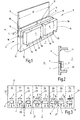
- the FIG. 1 shows a portion of a parapet wall 1 of a room 2 of a building or the like.
- the parapet wall 1 which belongs to the facade 3 of the room 1, adjacent to an air passage 4 leading from the inside of the room to the outside a.
- Above the air passage 4 is a window 5 of the room 2.
- the air passage 4 may be configured for example as a wall opening of the parapet wall 1.
- the room 2 is a decentralized ventilation device 6 assigned, which is modular and has a device structure with a supply air part 7, an exhaust air part 8 and a heat recovery part 9 as units 10.
- the building units 10 represent optional modules 11 used for the decentralized ventilation device 6. Since the supply air part 7 and the exhaust air part 8 are positioned inside the room 2, namely modules 11 arranged on the inside 12 of the parapet wall 1, these are room modules 13.
- the heat recovery part 9 is arranged in the wall opening formed as a wall opening 4, ie not within the room 2, but in the parapet wall 1, so that it forms a frame module 14. Since supply air part 7 and exhaust air part 8 are arranged laterally next to one another, they form neighboring devices 15.
- a portion of the rear side 16 of the supply air part 7 and a portion of the rear side 17 of the exhaust air part 8 are assigned to an inner side 18 of the heat recovery part 9.
- the arrangement is preferably such that the modules 11 each have their own module housing 19, which are fastened together to form a device housing of the decentralized ventilation device 6. It can be seen that the heights h and depths t of supply air part 7 and exhaust air part 8 are of the same size.
- the height h 'of the heat recovery part 9 is smaller than the height h of supply air part 7 and exhaust air part 8 is formed.
- the total width B of supply air part 7 and exhaust air part 8, that is, the sum of the individual widths of supply air part 7 and exhaust air part 8, is as large as the width B 'of the heat recovery part. 9
- FIG. 2 Based on the section of the FIG. 2 is the arrangement of FIG. 1 shown again, wherein the air passage 4 is realized as a breakthrough of the parapet wall 1 and in the embodiment of FIG. 2 not equipped with a heat recovery part 9.
- the FIG. 2 further shows a portion of the floor 20 and the ceiling 21 from the room 2.
- the design of the modular decentralized ventilation device 6 according to FIG. 1 is such that the supply air part 7 sucks in outside air through the heat recovery part 9 and introduces into the space 2.
- Zu povertyteil 7 is preferably a heat exchanger, to be able to treat the supplied outside air (primary air) thermally.
- the exhaust air part 8 carries secondary air, namely room air, via the heat recovery part 9 to the outside a, wherein in the winter, the procedure is such that by means of the heat recovery part 9, the supplied outside air is preheated by the exhaust air stream. In summer, the heat exchange is reversed, that is, the relatively warm outside air is cooled by means of the discharged secondary air.
- the decentralized ventilation device 6 is modular, also possible applications are conceivable in which, for example, no heat recovery should be performed so that the heat recovery part 9 is not used to build the decentralized ventilation device 6. In such a case, therefore, only the modules 11 of supply air part 7 and exhaust air part 8 are assembled and arranged in space 2.
- FIG. 3 shows various decentralized ventilation devices 6 in different rooms 2, 2 'and 2 "of a building or the like, the rooms 2, 2' and 2" are limited by room walls 22 and also each room 2, 2 ', 2 "at least one window axis 23 is assigned FIG. 3 shows a view of the interior facade of the three rooms 2, 2 '2 ". The windows of these rooms 2, 2' and 2" are not shown. However, the window axes 23, each extending between the respective windows, indicate that the room 2 has two windows, the room 2 'has three windows and the room 2 "also has three windows, and the windows axes 23 make zones 24 in the individual rooms 2, 2 'and 2 "formed.
- Each zone 24 is at least one decentralized ventilation device 6 or a module 11 of a decentralized ventilation device 6, wherein it may be - according to space 2 "- that a decentralized ventilation device 6 or a module 11 of a decentralized ventilation device 6 is located on a window axis 23.
- Each zone 24 has an air passage 4 leading from the interior of the room 2, 2 ', 2 "to the outside A.
- the air outlets 4 are shown in FIG FIG. 3 drawn above the respective modules 11 of the decentralized ventilation equipment 6.
- a device 6 which has only one exhaust air part 8.
- a device 6 is provided which has only one Zuluftteil 7.
- the adjacent zone 24 has a device 6, which has only one Zu Kunststoffteil 7.
- a decentralized ventilation device 6 that extends over two air outlets 4, wherein one air passage 4 is assigned an inlet air part 7 and the other air passage 4 is an exhaust air part 8.
- a heat recovery part 9 is not arranged in an air passage 4, but on the parapet wall 1.
- the space 2 has another decentralized ventilation device 6, which has a circulating-air part 25.
- the heat-recovery part 9 has an air / air heat exchanger, which can be designed as a cross-heat exchanger or as a heat-wheel device.
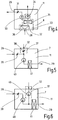
- the FIG. 4 shows a module 11 for a decentralized ventilation device 6, which is designed as an exhaust air part 8. It has an air inlet 28 and an air outlet 29, wherein an exhaust air fan 30 and a controllable air flap 31 are located between the air inlet 28 and the air outlet 29.
- this module 11 can be equipped with a further module 32, which in FIG. 4 outlined with a dashed line.
- the module 32 is a secondary air part 33 which has a secondary air fan 34, a secondary air heat exchanger 35 and, optionally, a common secondary air filter 36.
- the secondary air filter 36 is "common" because the exhaust air flow leading to the outside also passes through the secondary air filter 36. Secondary air, so room air, flows through the secondary air filter 36 and is led to the outside and / or passes the secondary air heat exchanger 35 and is introduced by means of the secondary air fan 34 back into the room 2 according to the recirculation principle.
- FIGS. 5 and 6 each show a module 11, which is designed as Zu povertyteil 7 and optionally can be equipped with a module 32, which is designed as a secondary air part 37.
- the secondary air part 37 preferably has a secondary air flap 38 or - according to the embodiment in FIG. 6 - A secondary air fan 46.
- the supply air part 7 has the FIG. 5 an air inlet 28, to which an air damper 39 connects, which leads both to the secondary air damper 38 and to a supply air fan 40, to which a Zulufttownleyer 41 connects, which leads to an air outlet 29.
- the secondary air damper 38 and / or the secondary air fan 34 are / is optional.
- the supply air ventilator 40 draws in ambient air when the air damper 39 is open and ambient air when the secondary air damper 38 is open and conveys it through the optional supply air heat exchanger 41 and brings the air through the air outlet 29 in the room 2 a.
- the primary air flow (outside air) via the supply air fan 40 and the secondary air flow (room air) is controlled via the secondary air fan 46.
- the FIG. 7 shows a decentralized ventilation device 6 with a schematically represented exhaust air part 8, a schematically illustrated Zu Kunststoffteil 7, a recirculation part 25 and a heat recovery part 9, which has an air / air heat exchanger 42, which is designed as a heat wheel 43.
- the inlet air part 7 has an air inlet 28 with adjoining air flap 39 and subsequent supply air fan 40, which supplies air to a region of the rotating heat wheel of the heat wheel 43, which is then passed through an air heat exchanger 41 to an air outlet 29 and there enter the room 2 can.
- Room air is supplied with respect to the exhaust part 8 to an air inlet 28, which is followed by a secondary air filter 36, which proportionally feeds the air to another area of the heat wheel of the heat wheel 43.
- this portion of air is fed via an exhaust fan 30 and an air flap 31 to an air outlet 29, which leads to the outside.
- Another portion of the secondary air is supplied from the secondary air filter 36 to a secondary air heat exchanger 35, which is followed by a secondary air fan 34, which is followed by an air outlet 29, which introduces the air in the space 2 as circulating air.
- the two mentioned areas of the heat wheel of the heat wheel 43 are separated by a partition 44, so that by means of the heat wheel heat exchange, but not an air exchange takes place.
- decentralized ventilation device 6 accordingly has - assembled in a modular manner - a supply air part 7, an exhaust air part 8, a circulating air part 25 and a heat recovery part 9.
Description
Die Erfindung betrifft ein dezentrales lufttechnisches Gerät zur Belüftung und/oder Klimatisierung eines Raumes.The invention relates to a decentralized ventilation device for ventilation and / or air conditioning of a room.
Dezentrale lufttechnische Geräte der vorstehend genannten Art sind bekannt. Sie werden zur Belüftung und/oder Klimatisierung von Räumen eines Gebäudes oder dergleichen verwendet, wobei sie autark arbeiten, also nicht an ein im Gebäude verlegtes Zuluftkanalsystem und/oder Abluftkanalsystem angeschlossen sind, sondern über vorzugsweise kurze Luftkanäle mit der Außenatmosphäre in Verbindung stehen. Im Gegensatz dazu sind zentrale lufttechnische Geräte an eine Klimazentrale des Gebäudes angeschlossen. Die bekannten dezentralen lufttechnischen Geräte weisen eine Zuluftzuführung sowie eine Abluftabführung und einen Wärmetauscher auf, um die in den Raum einzubringende Zuluft wärmetechnisch zu behandeln, also zu kühlen oder zu heizen. Bekannte dezentrale lufttechnische Geräte einer weiteren Bauform weisen zusätzlich eine Umluftführung auf, um Sekundärluft, also Raumluft, dem Raum zu entnehmen, mittels des Wärmetauschers zu behandeln und dann wieder in den selben Raum einzubringen. Ein gattungsgemäßes Gerät ist aus der Druckschrift
Der Erfindung liegt die Aufgabe zugrunde, ein dezentrales lufttechnisches Gerät zur Belüftung und/oder Klimatisierung eines Raumes zu schaffen, das ohne großen Aufwand individuell an die jeweilige Belüftungs- beziehungsweise Klimatisierungsaufgabe des konkreten Einsatzortes/Raumes erfüllt.The invention has for its object to provide a decentralized ventilation device for ventilation and / or air conditioning of a room that individually without great effort to the respective ventilation or air conditioning task of the specific site / room met.
Diese Aufgabe wird durch die Merkmalen von Anspruch 1 gelöst. In Abhängigkeit der Einsatzsituation wird daher stets das dezentrale lufttechnische System/Gerät eingesetzt, dabei jedoch individuell aufgrund des modularen Aufbaus angepasst. Der Geräteaufbau lässt sich durch die Verwendung von mindestens einem der Module oder Zusammenstellung verschiedener Module einsatzspezifisch gestalten. Auch ist eine problemlose Umrüstung und/oder Nachrüstung eines bereits installierten erfindungsgemäßen dezentralen lufttechnischen Geräts möglich, da nur Module ausgetauscht oder herausgenommen beziehungsweise hinzugefügt werden müssen. Das erfindungsgemäße System erfordert nur eine sehr geringe Lagerhaltung, da nur wenige Aufbauteile zur Erfüllung verschiedener Aufgaben bereitgestellt werden müssen, die in wunschgemäßer Kombination zum gesamten dezentralen lufttechnischen Gerät zusammengestellt werden können. Wird nur ein Zuluftteil beim dezentralen lufttechnischen Gerät benötigt, weil die Abluft beispielsweise über eine Raumverbindung zu anderen Räumen des Gebäudes abgeführt wird, so wird diesem dezentralen lufttechnischen Gerät kein Abluftteil zugeordnet. In Abhängigkeit von dem Wunsch, einen Raum durch Umluftführung zu klimatisieren oder mitzuklimatisieren, wird das dezentrale lufttechnische Gerät mit dem Umluftteil ausgestattet oder nicht. Soll eine Wärmerückgewinnung erfolgen, so ist hierfür ebenfalls eine modulartige Baueinheit vorgesehen, die optional zum Einsatz kommen kann.This object is solved by the features of
Nach einer Weiterbildung der Erfindung ist vorgesehen, dass das Wärmerückgewinnungsteil als Zargenmodul oder Raummodul ausgebildet ist. Unter "Zargenmodul" ist eine Baueinheit zu verstehen, die nicht im zu belüftenden oder zu klimatisierenden Raum, sondern in der Raumwand, Fassadenwand oder dergleichen angeordnet ist, also im Raum selber keinen oder so gut wie keinen Raum einnimmt. Ein "Raummodul" ist eine Baueinheit, die im Raum angeordnet ist, also Volumen des Raumes einnimmt. Sämtliche Module beziehungsweise Baueinheiten des dezentralen lufttechnischen Geräts sind nicht über große Entfernungen verteilt angeordnet, sondern stets zusammengefasst, also nah beieinander angeordnet, sodass insgesamt ein Gerät gebildet wird.According to a development of the invention it is provided that the heat recovery part is designed as a frame module or room module. Under "Zargenmodul" is a structural unit to understand that is not located in the room to be ventilated or air-conditioned, but in the room wall, façade wall or the like, so occupies no or virtually no space in the room itself. A "room module" is a structural unit that is arranged in space, ie occupies the volume of space. All modules or units of the decentralized ventilation device are not distributed over long distances, but always summarized, so arranged close to each other, so that a total of one device is formed.
Nach einer Weiterbildung der Erfindung ist vorgesehen, dass das Zuluftteil, das Abluftteil und/oder das Umluftteil als Raummodul/e ausgebildet ist/sind. Zuluftteil, Abluftteil und/oder Umluftteil befinden sich demnach innerhalb des zu belüftenden und/oder zu klimatisierenden Raumes. Dem gegenüber ist das Wärmerückgewinnungsmodul vorzugsweise als Zargenmodul ausgebildet, das heißt, es befindet sich in einem Aufnahmeraum einer Raumwand, insbesondere einer Fassadenwand, des Raumes. Der Aufnahmeraum kann einen Luftdurchlass nach außen bilden.According to a development of the invention, it is provided that the supply air part, the exhaust air part and / or the circulating air part is / are designed as a room module / s. Supply air part, exhaust air part and / or recirculation part are therefore located within the room to be ventilated and / or air-conditioned. In contrast, the heat recovery module is preferably designed as a frame module, that is, it is located in a receiving space of a room wall, in particular a facade wall, the room. The receiving space can form an air passage to the outside.
Grundsätzlich ist es möglich, das Zuluftteil, das Abluftteil, das Umluftteil und/oder das Wärmerückgewinnungsteil als Unterflurmodule und/oder Deckenmodule auszubilden. Besonders bevorzugt ist jedoch vorgesehen, dass das Zuluftteil, das Abluftteil, das Umluftteil und/oder das Wärmerückgewinnungsteil als Brüstungsmodul/e ausgebildet ist/sind. Diese Baueinheiten befinden sich daher im Bereich der Brüstung des Raumes, also unterhalb eines Fensters oder dergleichen des Raumes.In principle, it is possible to design the supply air part, the exhaust air part, the recirculation part and / or the heat recovery part as underfloor modules and / or ceiling modules. However, it is particularly preferably provided that the supply air part, the exhaust air part, the recirculation part and / or the heat recovery part is designed as a parapet module / s. These units are therefore in the range the balustrade of the room, so below a window or the like of the room.
Eine Weiterbildung der Erfindung sieht vor, dass Zuluftteil und Abluftteil als seitlich nebeneinander angeordnete Nachbargeräte ausgebildet sind. Die Nachbargeräte bilden zusammen - gegebenenfalls mit weiteren Modulen - das dezentrale lufttechnische Gerät, wobei durch die seitlich benachbart zueinander liegende Anordnung von Zuluftteil und Abluftteil innerhalb des Geräts nebeneinander liegende Zonen geschaffen werden, die der Zuluftführung beziehungsweise der Abluftführung dienen.A further development of the invention provides that the supply air part and the exhaust air part are designed as adjacent devices arranged side by side. The neighboring devices together - possibly with other modules - the decentralized ventilation device, which are created by the laterally adjacent to each other lying arrangement of supply air and exhaust air inside the unit adjacent zones that serve the supply air or exhaust duct.
Wird ein Wärmerückgewinnungsteil beim dezentralen lufttechnischen Gerät modulartig eingesetzt, so ist vorgesehen, dass zumindest ein Anteil der Rückseite von Zuluftteil und/oder Abluftteil an zumindest einem Bereich einer Innenseite des Wärmerückgewinnungsteils angrenzt. Die Rückseite von Zuluftteil und/oder Abluftteil steht somit dem Bereich der Innenseite des Wärmerückgewinnungsteils gegenüber oder grenzt unmittelbar an diesen an, sodass hier keine Nebeneinander-Bauweise, sondern eine Hintereinander-Bauweise realisiert ist.If a heat recovery part is used modularly in the decentralized ventilation device, then it is provided that at least a portion of the rear side of the supply air part and / or exhaust part adjoins at least one region of an inner side of the heat recovery part. The back side of the supply air part and / or exhaust air part thus faces the region of the inside of the heat recovery part or adjoins it directly, so that here no side-by-side construction, but a series construction is realized.
Ferner ist es vorteilhaft, wenn die Gesamtbreite von Zuluftteil und Abluftteil so groß wie die Breite des Wärmerückgewinnungsteils ist. In einem solchen Falle bestimmt die Gesamtbreite vorzugsweise die Gerätebreite des dezentralen lufttechnischen Geräts. Um die Module einander besonders einfach zuordnen zu können, ist vorgesehen, dass die Höhen und/oder Tiefen von Zuluftteil und Abluftteil gleich groß ausgebildet sind. Ferner kann vorzugsweise vorgesehen sein, dass die Höhe des Wärmerückgewinnungsteils kleiner als die Höhe(n) von Zuluftteil und/oder Abluftteil ist/sind.Furthermore, it is advantageous if the total width of supply air part and exhaust air part is as large as the width of the heat recovery part. In such a case, the total width preferably determines the device width of the decentralized ventilation device. In order to be able to associate the modules with each other in a particularly simple manner, it is provided that the heights and / or depths of the supply air part and the exhaust air part are of the same size. Furthermore, it can preferably be provided that the height of the heat recovery part is smaller than the height (s) of supply air part and / or exhaust air part is / are.
Das Wärmerückgewinnungsteil weist vorzugsweise für die Wärmerückgewinnung einen Luft/Luft-Wärmetauscher auf. Dieser kann bevorzugt als Kreuzwärmetauscher ausgebildet sein. Zusätzlich oder alternativ ist es denkbar, dass das Wärmerückgewinnungsteil eine Wärmeradvorrichtung aufweist. Diese besitzt ein sich langsam drehendes Wärmerad, das durch einen Luftstrom erwärmt oder gekühlt wird, wobei die Wärme oder Kälte von einem anderen Luftstrom genutzt wird, der das Wärmerad durchströmt, sobald es sich bis in die Position dieses anderen Luftstroms gedreht hat.The heat recovery part preferably has an air / air heat exchanger for heat recovery. This can preferably be designed as a cross-heat exchanger. Additionally or alternatively, it is conceivable that the heat recovery part has a heat wheel device. This has a slowly rotating heat wheel, which is heated or cooled by an air flow, the heat or cold is used by another air flow, which flows through the heat wheel, as soon as it has rotated to the position of this other air flow.
Bevorzugt ist das erfindungsgemäße dezentrale lufttechnische Gerät durch ein gemeinsames Gehäuse gekennzeichnet, dass für die Aufnahme von mindestens einem der Module geeignet ist. Zusätzlich oder alternativ kann vorgesehen sein, dass die Module eigene Modulgehäuse aufweisen. Mit diesen eigenen Modulgehäusen können die Module in das gemeinsame Gehäuse eingesetzt werden und/oder dass das/die Modulgehäuse ein Gerätegehäuse des dezentralen lufttechnischen Geräts bildet/bilden. Letzteres bedeutet, dass das Modulgehäuse eines Moduls selbst das Gerätegehäuse darstellt, wobei dann, wenn mehrere Module zusammengestellt werden, ihre Modulgehäuse insgesamt gesehen das Gerätegehäuse bilden. In einem solchen Falle werden die Modulgehäuse aneinander befestigt, wodurch das Gerätegehäuse entsteht.Preferably, the decentralized ventilation device according to the invention is characterized by a common housing that is suitable for receiving at least one of the modules. Additionally or alternatively it can be provided that the modules have their own module housing. With these own module housings, the modules can be used in the common housing and / or that the / the module housing forms / forms a device housing of the decentralized ventilation device. The latter means that the module housing of a module itself represents the device housing, wherein when several modules are put together, their module housing as a whole form the device housing. In such a case, the module housings are fastened to each other, whereby the device housing is formed.
Das dezentrale lufttechnische Gerät kann als Brüstungs-, Decken- und/oder Bodengerät ausgebildet sein. Das Wärmerückgewinnungsteil weist vorzugsweise mindestens einen Bypass auf, sodass bei der Verwendung des Bypasses ein Wärmeaustausch nicht oder nur teilweise erfolgt.The decentralized ventilation device can be designed as a parapet, ceiling and / or floor unit. The heat recovery part preferably has at least one bypass, so that in the Use of the bypass heat exchange is not or only partially.
Nach einer Weiterbildung der Erfindung ist vorgesehen, dass das Zuluftteil optional mit einem Sekundärluftteil, insbesondere Raumluftteil, ausrüstbar ist. Bei dieser Ausgestaltung ist demzufolge kein separates Abluftteil erforderlich, sondern in das modulartig aufgebaute Zuluftteil kann ein weiteres Modul, nämlich optional das Sekundärluftteil, eingesetzt werden. Natürlich sind auch lufttechnische Geräte denkbar, die als Baueinheiten sowohl ein Umluftteil als auch ein Zuluftteil aufweisen, wobei letzteres optional mit dem Sekundärluftteil, insbesondere Raumluftteil, ausrüstbar ist.According to a development of the invention, it is provided that the incoming air part can optionally be equipped with a secondary air part, in particular a room air part. In this embodiment, therefore, no separate exhaust air part is required, but in the module-like constructed Zuluftteil another module, namely optionally the secondary air part can be used. Of course, ventilation devices are also conceivable, which have both a recirculation part and a Zuluftteil as structural units, the latter optionally with the secondary air part, in particular room air part, can be equipped.
Ferner ist es vorteilhaft, wenn das Sekundärluftteil eine Sekundärluftklappe und/oder einen Sekundärluftventilator aufweist.Furthermore, it is advantageous if the secondary air part has a secondary air flap and / or a secondary air fan.
Von Vorteil ist, wenn das Zuluftteil einen Zuluftventilator aufweist.It is advantageous if the supply air part has a supply air fan.
Ferner ist es vorteilhaft, wenn das Zuluftteil optional mit einem Zuluftwärmetauscher ausrüstbar ist. Auch hier kann demzufolge dem modulartig aufgebauten Zuluftteil optional ein weiteres Modul, nämlich mit Zuluftwärmetauscher, zugeführt werden.Furthermore, it is advantageous if the incoming air part can optionally be equipped with a supply air heat exchanger. As a result, it is also possible here to optionally supply a further module, namely with a supply air heat exchanger, to the module-like intake part.
In gleicher Weise ist vorgesehen, dass das Abluftteil optional mit einem Sekundärluftwärmetauscher, insbesondere Raumluftwärmetauscher, ausrüstbar ist. Hierbei handelt es sich ebenfalls um ein optional einsetzbares Modul des als Baueinheit des dezentralen lufttechnischen Geräts ausgebildeten Moduls.In the same way, it is provided that the exhaust air part can optionally be equipped with a secondary air heat exchanger, in particular room air heat exchanger. This is likewise an optionally usable module of the module designed as a structural unit of the decentralized ventilation device.
Eine Weiterbildung der Erfindung sieht vor, dass das Abluftteil einen Abluftventilator aufweist. Ferner ist es vorteilhaft, wenn das Abluftteil einen Sekundärluftventilator, insbesondere Raumluftventilator, aufweist.A development of the invention provides that the exhaust part has an exhaust fan. Furthermore, it is advantageous if the exhaust air part a secondary air fan, in particular room air fan has.
Bevorzugt ist vorgesehen, dass das Abluftteil ein Sekundärluftfilter, insbesondere Raumluftfilter, oder ein Fortluft-Sekundärluftfilter aufweist.It is preferably provided that the exhaust air part has a secondary air filter, in particular room air filter, or an exhaust air secondary air filter.
Die Erfindung betrifft ferner eine lufttechnische Anlage in einem Raum zu dessen Belüftung und/oder Klimatisierung, mit mehreren dezentralen lufttechnischen Geräten nach einem oder mehreren der vorhergehenden Ansprüche, wobei die Geräte mit aus den Modulen gebildetem, unterschiedlichem Modulaufbau ausgestattet sind.The invention further relates to a ventilation system in a room for its ventilation and / or air conditioning, with a plurality of decentralized ventilation devices according to one or more of the preceding claims, wherein the devices are equipped with formed from the modules, different module structure.
Die lufttechnische Anlage ist vorzugsweise derart ausgebildet, dass der Raum mindestens eine Fensterachse aufweist und dass die Geräte neben und/oder auf der Fensterachse angeordnet sind. Unter "Fensterachse" ist eine imaginäre Achse zu verstehen, die vertikal verläuft und den Raum durch eine Zwischenebene aufteilen kann oder vertikal verlaufend ein Fenster, insbesondere mittig, teilt. Weist ein Raum beispielsweise drei nebeneinander liegende Fenster auf, so besitzt der Raum drei Fensterachsen, nämlich drei Vertikalachsen, die das jeweilige Fenster insbesondere mittig teilen.The ventilation system is preferably designed such that the space has at least one window axis and that the devices are arranged next to and / or on the window axis. "Window axis" is an imaginary axis that runs vertically and can divide the space by an intermediate level or vertically extending a window, especially in the middle divides. If a room has, for example, three adjacent windows, the room has three window axes, namely three vertical axes, which in particular share the respective window in the center.
Die Zeichnungen veranschaulichen die Erfindung anhand von Ausführungsbeispielen und zwar zeigt:
Figur 1- eine perspektivische Ansicht auf ein schematisch dargestelltes dezentrales lufttechnisches Gerät in einem schematisch angedeuteten, zu belüftenden und/oder zu klimatisierenden Raum,
Figur 2- einen Schnitt durch eine Anordnung ähnlich der der
Figur 1 Figur 3- mehrere Räume eines Gebäudes oder dergleichen mit dezentralen lufttechnischen Geräten,
Figur 4- ein Modul eines dezentralen lufttechnischen Geräts in Prinzipdarstellung,
Figur 5- eine Anordnung entsprechend der
Figur 4 , Figur 6- eine Anordnung entsprechend der
Figur 4 und Figur 7- eine Anordnung entsprechend der
Figur 4
- FIG. 1
- a perspective view of a schematically illustrated decentralized ventilation device in a schematically indicated, to be ventilated and / or air-conditioned space,
- FIG. 2
- a section through an arrangement similar to that of
FIG. 1 . - FIG. 3
- several rooms of a building or the like with decentralized ventilation equipment,
- FIG. 4
- a module of a decentralized ventilation device in schematic representation,
- FIG. 5
- an arrangement according to the
FIG. 4 . - FIG. 6
- an arrangement according to the
FIG. 4 and - FIG. 7
- an arrangement according to the
FIG. 4 ,
Die
Dem Raum 2 ist ein dezentrales lufttechnisches Gerät 6 zugeordnet, das modular aufgebaut ist und einen Geräteaufbau mit einem Zuluftteil 7, einem Abluftteil 8 und einem Wärmerückgewinnungsteil 9 als Baueinheiten 10 aufweist. Die Baueinheiten 10 stellen optional zum Einsatz kommende Module 11 des dezentralen lufttechnischen Geräts 6 dar. Da das Zuluftteil 7 und das Abluftteil 8 innerhalb des Raumes 2, nämlich auf der Innenseite 12 der Brüstungswand 1 angeordnete Module 11 positioniert sind, handelt es sich um Raummodule 13. Dem gegenüber ist das Wärmerückgewinnungsteil 9 in dem als Mauerdurchbruch ausgebildeten Luftdurchlass 4, also nicht innerhalb des Raumes 2, sondern in der Brüstungswand 1 angeordnet, sodass es ein Zargenmodul 14 bildet. Da Zuluftteil 7 und Abluftteil 8 seitlich nebeneinander angeordnet sind, bilden sie Nachbargeräte 15. Ein Anteil der Rückseite 16 des Zuluftteils 7 und ein Anteil der Rückseite 17 des Abluftteils 8 sind einer Innenseite 18 des Wärmerückgewinnungsteils 9 zugeordnet. Die Anordnung ist vorzugsweise derart getroffen, dass die Module 11 jeweils eigene Modulgehäuse 19 aufweisen, die zur Bildung eines Gerätegehäuses des dezentralen lufttechnischen Geräts 6 aneinander befestigt sind. Es ist erkennbar, dass die Höhen h und Tiefen t von Zuluftteil 7 und Abluftteil 8 gleichgroß ausgebildet sind. Die Höhe h' des Wärmerückgewinnungsteils 9 ist kleiner als die Höhe h von Zuluftteil 7 und Abluftteil 8 ausgebildet. Die Gesamtbreite B von Zuluftteil 7 und Abluftteil 8, also die Summe der einzelnen Breiten von Zuluftteil 7 und Abluftteil 8, ist ebenso groß wie die Breite B' des Wärmerückgewinnungsteils 9.The
Anhand des Schnittes der
Die Ausgestaltung des modular aufgebauten dezentralen lufttechnischen Geräts 6 gemäß
Da - wie bereits erwähnt - das dezentrale lufttechnische Gerät 6 modular aufgebaut ist, sind auch Einsatzmöglichkeiten denkbar, bei denen beispielsweise keine Wärmerückgewinnung durchgeführt werden soll, sodass das Wärmerückgewinnungsteil 9 nicht zum Aufbau des dezentralen lufttechnischen Geräts 6 verwendet wird. In einem solchen Falle werden demzufolge lediglich die Module 11 von Zuluftteil 7 und Abluftteil 8 zusammengestellt und im Raum 2 angeordnet.Since - as already mentioned - the
Die
Im Einzelnen gilt zur
Die
Die
Die
Das in der
Claims (27)
- A decentralized air related device for ventilation and/or air conditioning of a room, with a modular device configuration comprising a supply air part (7), an exhaust air part (8), a circulating air part (25) and a heat recovery part (9) as structural units (10), characterised in that the structural units (10) are embodied as optionally used modules (11) and that the heat recovery part (9) is embodied as a parapet module, which represents a frame module (14) and that the supply air part (7) and the exhaust air part (8) are embodied as room modules (13).
- The device according to claim 1, characterised in that the circulating air part (25) is embodied as room module (13).
- The device according to claim 1, characterised in that the circulating air part (25) is embodied as parapet module.
- The device according to any one of the preceding claims, characterised in that supply air part (7) and exhaust air part (8) are embodied as neighbouring devices (15), which are arranged laterally next to one another.
- The device according to any one of the preceding claims, characterised in that at least a portion of the rear side (16, 17) of supply air part (7) and/or exhaust air part (8) adjoin on at least an area of an inner side (18) of the heat recovery part (9).
- The device according to any one of the preceding claims, characterised in that the total width (B) of supply air part (7) and exhaust air part (8) is as large as the width (B') of the heat recovery part (9).
- The device according to any one of the preceding claims, characterised in that the heights (h) and/or depths (t) of supply air part (7) and exhaust air part (8) are embodied to have the same size.
- The device according to any one of the preceding claims, characterised in that the height (h') of the heat recovery part (9) is/are smaller than the height(s) (h) of supply air part (7) and/or exhaust air part (8).
- The device according to any one of the preceding claims, characterised in that the heat recovery part (9) is an air-to-air heat exchanger (42).
- The device according to claim 9, characterised in that the air-to-air heat exchanger (42) is embodied as cross-flow heat exchanger.
- The device according to claim 9 or 10, characterised in that the heat recovery part (9) is a rotary heat exchanger (43).
- The device according to any one of the preceding claims, characterised by a common housing for accommodating at least one of the modules (11).
- The device according to any one of the preceding claims, characterised in that the modules (11) have their own module housings.
- The device according to claim 13, characterised in that the module housing(s) forms/form a device housing.
- The device according to any one of the preceding claims 13 or 14, characterised in that the module housings are fastened to one another.
- The device according to any one of the preceding claims, characterised by the formation as parapet, ceiling and/or floor device.
- The device according to any one of the preceding claims, characterised in that the heat recovery part (9) has at least one bypass.
- The device according to any one of the preceding claims, characterised in that the supply air part (7) can optionally be equipped with a secondary air part (37), in particular room air part.
- The device according to claim 18, characterised in that the secondary air part (37) has a secondary air flap (38) and/or a secondary air ventilator (46).
- The device according to any one of the preceding claims, characterised in that the supply air part (7) has a supply air ventilator (40).
- The device according to any one of the preceding claims, characterised in that the supply air part (7) can optionally be equipped with a supply air heat exchanger (41).
- The device according to any one of the preceding claims, characterised in that the exhaust air part (8) can optionally be equipped with a secondary air heat exchanger (35), in particular room air heat exchanger.
- The device according to any one of the preceding claims, characterised in that the exhaust air part (8) has an exhaust air ventilator (30).
- The device according to any one of the preceding claims, characterised in that the exhaust air part (8) has a secondary air ventilator, in particular room air ventilator.
- The device according to any one of the preceding claims, characterised in that the exhaust air part has a secondary air filter, in particular room air filter, or an outgoing air secondary air filter (36).
- An air related assembly in a room (2) for the ventilation and/or air conditioning thereof, comprising a plurality of decentralized ventilation devices (6) according to any one or a plurality of the preceding claims, characterised in that the devices (6) are equipped with different modular design formed from the modules (11).
- The air related system according to claim 26, characterised in that the room (2) has at least one window axis (23) and that the devices (6) are arranged next to and/or on the window axis (23).
Applications Claiming Priority (1)
| Application Number | Priority Date | Filing Date | Title |
|---|---|---|---|
| DE102008046361A DE102008046361A1 (en) | 2008-09-09 | 2008-09-09 | Decentralized ventilation device and ventilation system with such a device |
Publications (3)
| Publication Number | Publication Date |
|---|---|
| EP2161512A2 EP2161512A2 (en) | 2010-03-10 |
| EP2161512A3 EP2161512A3 (en) | 2013-05-01 |
| EP2161512B1 true EP2161512B1 (en) | 2017-06-21 |
Family
ID=41213499
Family Applications (1)
| Application Number | Title | Priority Date | Filing Date |
|---|---|---|---|
| EP09010319.3A Active EP2161512B1 (en) | 2008-09-09 | 2009-08-11 | Decentralised ventilation device and ventilation assembly with such a device |
Country Status (2)
| Country | Link |
|---|---|
| EP (1) | EP2161512B1 (en) |
| DE (1) | DE102008046361A1 (en) |
Families Citing this family (3)
| Publication number | Priority date | Publication date | Assignee | Title |
|---|---|---|---|---|
| HK1147020A2 (en) * | 2011-01-14 | 2011-07-22 | Akos R & D Ltd | Air treatment apparatus and method |
| FI20140087A (en) * | 2014-03-26 | 2015-09-27 | Janovent Oy | Room-specific ventilation beam and chain of ventilation beams |
| CN105757865B (en) * | 2016-03-23 | 2018-12-07 | 佛山市城市森林净化科技有限公司 | A kind of combination type air Humidifier |
Family Cites Families (6)
| Publication number | Priority date | Publication date | Assignee | Title |
|---|---|---|---|---|
| DE2006527A1 (en) * | 1970-02-13 | 1971-08-26 | Krupp Gmbh | Air conditioner |
| DE3112394A1 (en) * | 1980-07-22 | 1982-07-08 | Eltreva AG, 4147 Aesch | "DEVICE FOR AIR CONTROL OF AN ENERGY FACADE" |
| DE10253264C5 (en) * | 2002-01-17 | 2008-04-17 | Ltg Aktiengesellschaft | Decentralized ventilation device and method for decentralized heating or cooling of a room |
| DE202004018206U1 (en) * | 2004-11-18 | 2005-01-27 | Von Staudach, Karl | Climate control assembly has a ventilator with heating and ventilation components e.g. a heat exchanger, compressor |
| DE102005011222A1 (en) * | 2005-03-11 | 2006-09-21 | Stiebel Eltron Gmbh & Co. Kg | Ventilation system for use in building, has housing with connections for supply, outlet, exhaust, and external air, where connections for supply and external air are exchanged when installation position of fan/heat exchanger are changed |
| DE102005045871A1 (en) * | 2005-09-22 | 2007-03-29 | Ltg Ag | Decentralized room ventilation device e.g. facade climate module-device, for use in building, has air-conditioning components arranged in housing designed as flat longitudinal housing, and partition device with partition housing |
-
2008
- 2008-09-09 DE DE102008046361A patent/DE102008046361A1/en not_active Withdrawn
-
2009
- 2009-08-11 EP EP09010319.3A patent/EP2161512B1/en active Active
Also Published As
| Publication number | Publication date |
|---|---|
| DE102008046361A1 (en) | 2010-03-11 |
| EP2161512A3 (en) | 2013-05-01 |
| EP2161512A2 (en) | 2010-03-10 |
Similar Documents
| Publication | Publication Date | Title |
|---|---|---|
| DE10010832C1 (en) | Device for temperature control and / or ventilation of a room | |
| EP1918650B1 (en) | Air-conditioning method for a room and air-conditioning device | |
| DE2754166A1 (en) | HEATING AND AIR CONDITIONING SYSTEM | |
| EP1130331B1 (en) | Method and device for the ventilation and the temperature controlling of a room | |
| DE202009004141U1 (en) | Modular and façade-integrated ventilation and air conditioning system | |
| EP1832818B1 (en) | Ventilation system | |
| EP2846108B1 (en) | Ceiling-type supply air outlet | |
| EP1772679B1 (en) | Decentralised room air treating device | |
| EP2161512B1 (en) | Decentralised ventilation device and ventilation assembly with such a device | |
| DE202007001429U1 (en) | Heating, cooling and/or ventilating device for rooms in building has ventilation device connected directly and/or indirectly to wall apertures | |
| DE102008045829B4 (en) | drying device | |
| DE3248227A1 (en) | Enclosing surround for doors or windows, and casing structural part, in particular roller-blind casing, for use above the surround | |
| DE202004018206U1 (en) | Climate control assembly has a ventilator with heating and ventilation components e.g. a heat exchanger, compressor | |
| EP0374527A2 (en) | Air distribution system | |
| EP3995749B1 (en) | Ventilation unit air line component | |
| WO2023089138A1 (en) | System for climate-control of interior spaces of a building | |
| EP1947398B1 (en) | Installation for heating, cooling and/or ventilating a room in a building | |
| AT508645B1 (en) | HOUSING VENTILATION SYSTEM | |
| DE202022101436U1 (en) | Air conditioning system | |
| EP4119853A1 (en) | Air recirculation module | |
| WO2014184601A1 (en) | Floor-cooling and -heating apparatus | |
| DE19504931A1 (en) | Air conditioning for room | |
| DE2714819A1 (en) | VENTILATION SYSTEM | |
| DE3025342A1 (en) | Air conditioning system for factory halls - has main and auxiliary air outlets in vertical arrangement, some discharging horizontally and some obliquely | |
| AT17894U1 (en) | Heat transfer device for cooling or heating rooms |
Legal Events
| Date | Code | Title | Description |
|---|---|---|---|
| PUAI | Public reference made under article 153(3) epc to a published international application that has entered the european phase |
Free format text: ORIGINAL CODE: 0009012 |
|
| AK | Designated contracting states |
Kind code of ref document: A2 Designated state(s): AT BE BG CH CY CZ DE DK EE ES FI FR GB GR HR HU IE IS IT LI LT LU LV MC MK MT NL NO PL PT RO SE SI SK SM TR |
|
| AX | Request for extension of the european patent |
Extension state: AL BA RS |
|
| PUAL | Search report despatched |
Free format text: ORIGINAL CODE: 0009013 |
|
| AK | Designated contracting states |
Kind code of ref document: A3 Designated state(s): AT BE BG CH CY CZ DE DK EE ES FI FR GB GR HR HU IE IS IT LI LT LU LV MC MK MT NL NO PL PT RO SE SI SK SM TR |
|
| AX | Request for extension of the european patent |
Extension state: AL BA RS |
|
| RIC1 | Information provided on ipc code assigned before grant |
Ipc: F24F 13/20 20060101ALI20130328BHEP Ipc: F24F 12/00 20060101AFI20130328BHEP |
|
| 17P | Request for examination filed |
Effective date: 20131104 |
|
| RBV | Designated contracting states (corrected) |
Designated state(s): AT BE BG CH CY CZ DE DK EE ES FI FR GB GR HR HU IE IS IT LI LT LU LV MC MK MT NL NO PL PT RO SE SI SK SM TR |
|
| GRAP | Despatch of communication of intention to grant a patent |
Free format text: ORIGINAL CODE: EPIDOSNIGR1 |
|
| GRAJ | Information related to disapproval of communication of intention to grant by the applicant or resumption of examination proceedings by the epo deleted |
Free format text: ORIGINAL CODE: EPIDOSDIGR1 |
|
| INTG | Intention to grant announced |
Effective date: 20161116 |
|
| INTC | Intention to grant announced (deleted) | ||
| GRAP | Despatch of communication of intention to grant a patent |
Free format text: ORIGINAL CODE: EPIDOSNIGR1 |
|
| INTG | Intention to grant announced |
Effective date: 20170125 |
|
| GRAS | Grant fee paid |
Free format text: ORIGINAL CODE: EPIDOSNIGR3 |
|
| GRAA | (expected) grant |
Free format text: ORIGINAL CODE: 0009210 |
|
| AK | Designated contracting states |
Kind code of ref document: B1 Designated state(s): AT BE BG CH CY CZ DE DK EE ES FI FR GB GR HR HU IE IS IT LI LT LU LV MC MK MT NL NO PL PT RO SE SI SK SM TR |
|
| REG | Reference to a national code |
Ref country code: GB Ref legal event code: FG4D Free format text: NOT ENGLISH |
|
| REG | Reference to a national code |
Ref country code: CH Ref legal event code: EP |
|
| REG | Reference to a national code |
Ref country code: IE Ref legal event code: FG4D Free format text: LANGUAGE OF EP DOCUMENT: GERMAN |
|
| REG | Reference to a national code |
Ref country code: AT Ref legal event code: REF Ref document number: 903322 Country of ref document: AT Kind code of ref document: T Effective date: 20170715 |
|
| REG | Reference to a national code |
Ref country code: DE Ref legal event code: R096 Ref document number: 502009014081 Country of ref document: DE |
|
| REG | Reference to a national code |
Ref country code: NL Ref legal event code: FP |
|
| REG | Reference to a national code |
Ref country code: FR Ref legal event code: PLFP Year of fee payment: 9 |
|
| REG | Reference to a national code |
Ref country code: CH Ref legal event code: NV Representative=s name: OFFICE ERNEST T. FREYLINGER S.A., CH |
|
| PGFP | Annual fee paid to national office [announced via postgrant information from national office to epo] |
Ref country code: LU Payment date: 20170821 Year of fee payment: 9 Ref country code: NL Payment date: 20170821 Year of fee payment: 9 |
|
| PG25 | Lapsed in a contracting state [announced via postgrant information from national office to epo] |
Ref country code: HR Free format text: LAPSE BECAUSE OF FAILURE TO SUBMIT A TRANSLATION OF THE DESCRIPTION OR TO PAY THE FEE WITHIN THE PRESCRIBED TIME-LIMIT Effective date: 20170621 Ref country code: GR Free format text: LAPSE BECAUSE OF FAILURE TO SUBMIT A TRANSLATION OF THE DESCRIPTION OR TO PAY THE FEE WITHIN THE PRESCRIBED TIME-LIMIT Effective date: 20170922 Ref country code: FI Free format text: LAPSE BECAUSE OF FAILURE TO SUBMIT A TRANSLATION OF THE DESCRIPTION OR TO PAY THE FEE WITHIN THE PRESCRIBED TIME-LIMIT Effective date: 20170621 Ref country code: NO Free format text: LAPSE BECAUSE OF FAILURE TO SUBMIT A TRANSLATION OF THE DESCRIPTION OR TO PAY THE FEE WITHIN THE PRESCRIBED TIME-LIMIT Effective date: 20170921 Ref country code: LT Free format text: LAPSE BECAUSE OF FAILURE TO SUBMIT A TRANSLATION OF THE DESCRIPTION OR TO PAY THE FEE WITHIN THE PRESCRIBED TIME-LIMIT Effective date: 20170621 |
|
| PGFP | Annual fee paid to national office [announced via postgrant information from national office to epo] |
Ref country code: GB Payment date: 20170707 Year of fee payment: 9 Ref country code: FR Payment date: 20170822 Year of fee payment: 9 Ref country code: CH Payment date: 20170821 Year of fee payment: 9 |
|
| REG | Reference to a national code |
Ref country code: LT Ref legal event code: MG4D |
|
| PG25 | Lapsed in a contracting state [announced via postgrant information from national office to epo] |
Ref country code: SE Free format text: LAPSE BECAUSE OF FAILURE TO SUBMIT A TRANSLATION OF THE DESCRIPTION OR TO PAY THE FEE WITHIN THE PRESCRIBED TIME-LIMIT Effective date: 20170621 Ref country code: LV Free format text: LAPSE BECAUSE OF FAILURE TO SUBMIT A TRANSLATION OF THE DESCRIPTION OR TO PAY THE FEE WITHIN THE PRESCRIBED TIME-LIMIT Effective date: 20170621 Ref country code: BG Free format text: LAPSE BECAUSE OF FAILURE TO SUBMIT A TRANSLATION OF THE DESCRIPTION OR TO PAY THE FEE WITHIN THE PRESCRIBED TIME-LIMIT Effective date: 20170921 |
|
| PGFP | Annual fee paid to national office [announced via postgrant information from national office to epo] |
Ref country code: BE Payment date: 20170821 Year of fee payment: 9 Ref country code: AT Payment date: 20170822 Year of fee payment: 9 |
|
| PG25 | Lapsed in a contracting state [announced via postgrant information from national office to epo] |
Ref country code: RO Free format text: LAPSE BECAUSE OF FAILURE TO SUBMIT A TRANSLATION OF THE DESCRIPTION OR TO PAY THE FEE WITHIN THE PRESCRIBED TIME-LIMIT Effective date: 20170621 Ref country code: CZ Free format text: LAPSE BECAUSE OF FAILURE TO SUBMIT A TRANSLATION OF THE DESCRIPTION OR TO PAY THE FEE WITHIN THE PRESCRIBED TIME-LIMIT Effective date: 20170621 Ref country code: SK Free format text: LAPSE BECAUSE OF FAILURE TO SUBMIT A TRANSLATION OF THE DESCRIPTION OR TO PAY THE FEE WITHIN THE PRESCRIBED TIME-LIMIT Effective date: 20170621 Ref country code: EE Free format text: LAPSE BECAUSE OF FAILURE TO SUBMIT A TRANSLATION OF THE DESCRIPTION OR TO PAY THE FEE WITHIN THE PRESCRIBED TIME-LIMIT Effective date: 20170621 |
|
| PG25 | Lapsed in a contracting state [announced via postgrant information from national office to epo] |
Ref country code: IS Free format text: LAPSE BECAUSE OF FAILURE TO SUBMIT A TRANSLATION OF THE DESCRIPTION OR TO PAY THE FEE WITHIN THE PRESCRIBED TIME-LIMIT Effective date: 20171021 Ref country code: ES Free format text: LAPSE BECAUSE OF FAILURE TO SUBMIT A TRANSLATION OF THE DESCRIPTION OR TO PAY THE FEE WITHIN THE PRESCRIBED TIME-LIMIT Effective date: 20170621 Ref country code: PL Free format text: LAPSE BECAUSE OF FAILURE TO SUBMIT A TRANSLATION OF THE DESCRIPTION OR TO PAY THE FEE WITHIN THE PRESCRIBED TIME-LIMIT Effective date: 20170621 Ref country code: SM Free format text: LAPSE BECAUSE OF FAILURE TO SUBMIT A TRANSLATION OF THE DESCRIPTION OR TO PAY THE FEE WITHIN THE PRESCRIBED TIME-LIMIT Effective date: 20170621 |
|
| PGFP | Annual fee paid to national office [announced via postgrant information from national office to epo] |
Ref country code: IT Payment date: 20171026 Year of fee payment: 9 |
|
| REG | Reference to a national code |
Ref country code: DE Ref legal event code: R097 Ref document number: 502009014081 Country of ref document: DE |
|
| PG25 | Lapsed in a contracting state [announced via postgrant information from national office to epo] |
Ref country code: MC Free format text: LAPSE BECAUSE OF FAILURE TO SUBMIT A TRANSLATION OF THE DESCRIPTION OR TO PAY THE FEE WITHIN THE PRESCRIBED TIME-LIMIT Effective date: 20170621 |
|
| PLBE | No opposition filed within time limit |
Free format text: ORIGINAL CODE: 0009261 |
|
| STAA | Information on the status of an ep patent application or granted ep patent |
Free format text: STATUS: NO OPPOSITION FILED WITHIN TIME LIMIT |
|
| PG25 | Lapsed in a contracting state [announced via postgrant information from national office to epo] |
Ref country code: DK Free format text: LAPSE BECAUSE OF FAILURE TO SUBMIT A TRANSLATION OF THE DESCRIPTION OR TO PAY THE FEE WITHIN THE PRESCRIBED TIME-LIMIT Effective date: 20170621 |
|
| 26N | No opposition filed |
Effective date: 20180322 |
|
| REG | Reference to a national code |
Ref country code: IE Ref legal event code: MM4A |
|
| PG25 | Lapsed in a contracting state [announced via postgrant information from national office to epo] |
Ref country code: IE Free format text: LAPSE BECAUSE OF NON-PAYMENT OF DUE FEES Effective date: 20170811 |
|
| PG25 | Lapsed in a contracting state [announced via postgrant information from national office to epo] |
Ref country code: SI Free format text: LAPSE BECAUSE OF FAILURE TO SUBMIT A TRANSLATION OF THE DESCRIPTION OR TO PAY THE FEE WITHIN THE PRESCRIBED TIME-LIMIT Effective date: 20170621 |
|
| PG25 | Lapsed in a contracting state [announced via postgrant information from national office to epo] |
Ref country code: MT Free format text: LAPSE BECAUSE OF FAILURE TO SUBMIT A TRANSLATION OF THE DESCRIPTION OR TO PAY THE FEE WITHIN THE PRESCRIBED TIME-LIMIT Effective date: 20170621 |
|
| REG | Reference to a national code |
Ref country code: CH Ref legal event code: PL |
|
| REG | Reference to a national code |
Ref country code: NL Ref legal event code: MM Effective date: 20180901 |
|
| REG | Reference to a national code |
Ref country code: AT Ref legal event code: MM01 Ref document number: 903322 Country of ref document: AT Kind code of ref document: T Effective date: 20180811 |
|
| GBPC | Gb: european patent ceased through non-payment of renewal fee |
Effective date: 20180811 |
|
| PG25 | Lapsed in a contracting state [announced via postgrant information from national office to epo] |
Ref country code: LI Free format text: LAPSE BECAUSE OF NON-PAYMENT OF DUE FEES Effective date: 20180831 Ref country code: LU Free format text: LAPSE BECAUSE OF NON-PAYMENT OF DUE FEES Effective date: 20180811 Ref country code: CH Free format text: LAPSE BECAUSE OF NON-PAYMENT OF DUE FEES Effective date: 20180831 Ref country code: AT Free format text: LAPSE BECAUSE OF NON-PAYMENT OF DUE FEES Effective date: 20180811 |
|
| REG | Reference to a national code |
Ref country code: BE Ref legal event code: MM Effective date: 20180831 |
|
| PG25 | Lapsed in a contracting state [announced via postgrant information from national office to epo] |
Ref country code: NL Free format text: LAPSE BECAUSE OF NON-PAYMENT OF DUE FEES Effective date: 20180901 Ref country code: HU Free format text: LAPSE BECAUSE OF FAILURE TO SUBMIT A TRANSLATION OF THE DESCRIPTION OR TO PAY THE FEE WITHIN THE PRESCRIBED TIME-LIMIT; INVALID AB INITIO Effective date: 20090811 |
|
| PG25 | Lapsed in a contracting state [announced via postgrant information from national office to epo] |
Ref country code: IT Free format text: LAPSE BECAUSE OF NON-PAYMENT OF DUE FEES Effective date: 20180811 |
|
| PG25 | Lapsed in a contracting state [announced via postgrant information from national office to epo] |
Ref country code: BE Free format text: LAPSE BECAUSE OF NON-PAYMENT OF DUE FEES Effective date: 20180831 Ref country code: FR Free format text: LAPSE BECAUSE OF NON-PAYMENT OF DUE FEES Effective date: 20180831 |
|
| PG25 | Lapsed in a contracting state [announced via postgrant information from national office to epo] |
Ref country code: CY Free format text: LAPSE BECAUSE OF NON-PAYMENT OF DUE FEES Effective date: 20170621 Ref country code: GB Free format text: LAPSE BECAUSE OF NON-PAYMENT OF DUE FEES Effective date: 20180811 |
|
| PG25 | Lapsed in a contracting state [announced via postgrant information from national office to epo] |
Ref country code: MK Free format text: LAPSE BECAUSE OF FAILURE TO SUBMIT A TRANSLATION OF THE DESCRIPTION OR TO PAY THE FEE WITHIN THE PRESCRIBED TIME-LIMIT Effective date: 20170621 |
|
| PG25 | Lapsed in a contracting state [announced via postgrant information from national office to epo] |
Ref country code: TR Free format text: LAPSE BECAUSE OF FAILURE TO SUBMIT A TRANSLATION OF THE DESCRIPTION OR TO PAY THE FEE WITHIN THE PRESCRIBED TIME-LIMIT Effective date: 20170621 |
|
| PG25 | Lapsed in a contracting state [announced via postgrant information from national office to epo] |
Ref country code: PT Free format text: LAPSE BECAUSE OF FAILURE TO SUBMIT A TRANSLATION OF THE DESCRIPTION OR TO PAY THE FEE WITHIN THE PRESCRIBED TIME-LIMIT Effective date: 20170621 |
|
| PGFP | Annual fee paid to national office [announced via postgrant information from national office to epo] |
Ref country code: DE Payment date: 20230824 Year of fee payment: 15 |