EP2244162B1 - Postenverfolgungs- und Verarbeitungssysteme und -verfahren - Google Patents
Postenverfolgungs- und Verarbeitungssysteme und -verfahren Download PDFInfo
- Publication number
- EP2244162B1 EP2244162B1 EP10172960.6A EP10172960A EP2244162B1 EP 2244162 B1 EP2244162 B1 EP 2244162B1 EP 10172960 A EP10172960 A EP 10172960A EP 2244162 B1 EP2244162 B1 EP 2244162B1
- Authority
- EP
- European Patent Office
- Prior art keywords
- beacon
- display
- information
- items
- data acquisition
- Prior art date
- Legal status (The legal status is an assumption and is not a legal conclusion. Google has not performed a legal analysis and makes no representation as to the accuracy of the status listed.)
- Expired - Lifetime
Links
Images


Classifications
-
- B—PERFORMING OPERATIONS; TRANSPORTING
- B07—SEPARATING SOLIDS FROM SOLIDS; SORTING
- B07C—POSTAL SORTING; SORTING INDIVIDUAL ARTICLES, OR BULK MATERIAL FIT TO BE SORTED PIECE-MEAL, e.g. BY PICKING
- B07C3/00—Sorting according to destination
- B07C3/20—Arrangements for facilitating the visual reading of addresses, e.g. display arrangements coding stations
-
- B—PERFORMING OPERATIONS; TRANSPORTING
- B07—SEPARATING SOLIDS FROM SOLIDS; SORTING
- B07C—POSTAL SORTING; SORTING INDIVIDUAL ARTICLES, OR BULK MATERIAL FIT TO BE SORTED PIECE-MEAL, e.g. BY PICKING
- B07C7/00—Sorting by hand only e.g. of mail
- B07C7/005—Computer assisted manual sorting, e.g. for mail
Definitions
- the field of the present invention includes the tracking and processing of items.
- the present invention involves the communication of sorting instructions to a person during the processing of parcels.
- the manual sorting or item-processing environment is readily described as a wide range of event-based stimuli with physical dynamic activity.
- the current state of parcel processing is one where people who process parcels within a manual sorting facility are continually reading package information from each package's label. Given the acquired information, a range of decision types and activity are possible for each job type (the "per-package decision process"). Items are moved between job positions in sorting facilities using a flexible array of conveyor belts, slides, trays, bags, carts, etc. Large-scale item processors, such as for example, UPS, have a substantial investment in the numerous facilities, plant equipment configurations, and training needed to provide the current state of the process.
- UPS Large-scale item processors
- off-the-floor exception handling may be able to reduce physical exception handling.
- These systems may use item acquire and re-acquire stations whereby instances of label acquisition exceptions and instruction-change exceptions are handled electronically rather than manually.
- the use of off-the-floor exception areas enabled by fixed item acquire and re-acquire stations imposes an early processing deadline and does not allow for instruction changes after an item has passed the re-acquire station.
- this method still requires considerable on-the-floor equipment for both, acquire and re-acquire stations.
- Embodiments of the present invention overcome many of the challenges present in the art, some of which are presented above.
- Embodiments of the present invention provide computer-assisted decision capability for the processing of items.
- an embodiment of the present invention tracks and provides processing instructions for items within an item processing facility's handling processes.
- items are tracked and information about one or more items is provided to a person based on the location of the person and/or the location of the one or more items.
- an embodiment of the invention involves a system whereby item handling personnel and supervisors wear a set of see-through display lenses that superimpose relevant messages proximately about or over real tracked objects in the field of view. These lenses are attached to an information gathering device that captures and decodes information about the item such as, for example, label images, and an orientation and position device that determines the orientation and position of the wearer so that it may be determined what items are in the field of view.
- an information gathering device that captures and decodes information about the item such as, for example, label images
- an orientation and position device that determines the orientation and position of the wearer so that it may be determined what items are in the field of view.
- Embodiments of the present invention involve a data acquisition and display device comprised of an information gathering device to capture data from an object, a beacon detection device to capture information about the orientation and position of a wearer, and a transparent heads-up display showing instructions related to the object, each in communication with one or more computers.
- a tracking system such as, for example, an optical tracking system comprised of two or more fixed detectors such as, for example, fixed cameras, one or more energy sources such as, for example, a light source, a passive beacon that is reactive to energy from the energy source, and a computer.
- the computer determines the location of the passive beacon from the information received from the fixed detectors as the detectors receive reflected or transmitted energy from the passive beacon.
- an item tracking system comprised of an information gathering device such as, for example, an image device to capture data from an object, a beacon detection device to capture information about the orientation and position of a wearer, a tracking system to follow a passive beacon applied to each object, and a transparent heads-up display showing infomation related to the object, each in communication with one or more computers.
- an information gathering device such as, for example, an image device to capture data from an object
- a beacon detection device to capture information about the orientation and position of a wearer
- a tracking system to follow a passive beacon applied to each object
- a transparent heads-up display showing infomation related to the object, each in communication with one or more computers.
- One aspect of the invention includes systems and methods for the use of tracking technology such as, for example, optical tracking technology, to follow the progress of an object moving through a complex facility in real time such as, for example, the optical tracking of parcels or parts on an assembly line or through a warehouse.
- tracking technology such as, for example, optical tracking technology
- Another aspect of the invention includes systems and methods for the use of a transparent heads-up display to convey instructions or information to a person when looking at a certain object.
- Such instructions could be for package handling, baggage handling, parts assembly, navigation through marked waypoints, item retrieval and packaging, inventory control, and the like.
- Yet another aspect of the invention is systems and methods for calibrating an optical tracking system using fixed cameras and passive beacons.
- the system is comprised of a tracking system that is configured to provide location information for each of a plurality of items on a surface and a display device.
- the display device is for viewing characteristic information for each of the plurality of items at their respective locations.
- the characteristic information is positioned to indicate the relative position of the item on the surface, including putting the characteristic information substantially proximate to a representation of the item.
- only certain characteristic information such as, for example, a zip code of a package, is displayed instead of the package at the package's position. Items may be singulated or non-singulated.
- These computer program instructions may also be stored in a computer-readable memory that can direct a computer or other programmable data processing apparatus to function in a particular manner, such that the instructions stored in the computer-readable memory produce an article of manufacture including instruction means that implement the function specified in the flowchart block or blocks.
- the computer program instructions may also be loaded onto a computer or other programmable data processing apparatus to cause a series of operational steps to be performed on the computer or other programmable apparatus to produce a computer implemented process such that the instructions that execute on the computer or other programmable apparatus provide steps for implementing the functions specified in the flowchart block or blocks.
- blocks of the block diagrams and flowchart illustrations support combinations of means for performing the specified functions, combinations of steps for performing the specified functions and program instruction means for performing the specified functions. It will also be understood that each block of the block diagrams and flowchart illustrations, and combinations of blocks in the block diagrams and flowchart illustrations, can be implemented by special purpose hardware-based computer systems that perform the specified functions or steps, or combinations of special purpose hardware and computer instructions.
- the concepts of the various embodiments of the invention relate to systems and methods for the processing of singulated and non-singulated items.
- the embodiments of the systems and methods generally involve two sub-systems, a data acquisition and display system and a tracking system such as, for example, an optical tracking system.
- the data acquisition and display system includes a set of goggles that have one or more information gathering devices such as, for example, cameras, radio-frequency identification (RFID) readers, barcode readers, RF receivers, etc., or combinations thereof for data capture and a transparent heads-up display for displaying data and tracking items. Items may be singulated or non-singulated and they may be stationary or moving.
- RFID radio-frequency identification
- Data capturing and tracking for this embodiment is initiated by pointing at least one of the information gathering devices on the goggles toward a label or tag on an item and initiating tracking of the item by, for example, uncovering a passive beacon, such as, for example, a retro-reflective dot proximately located on each item.
- the data captured by the goggle's image gathering device is transmitted via a network to a local computer that records item data and determines the instructions to be displayed in the heads-up display.
- the local computer may interface with one or more servers and business applications.
- the data acquisition and display may be performed by more than one device.
- information gathering devices may be mounted on the goggles, or they may be separate from the goggles such as wand-mounted or fixed barcode readers, RFID readers, cameras, etc.
- the display may be separate from the goggles, as it may be a fixed display monitor or panel as are known in the art, or it may be a display affixed to a person by means other than goggle.
- the display may be of the sort that items are viewed through the display and characteristic information about the items is displayed on or substantially proximate to the viewed items.
- a representation of one or more items may be displayed on the display and characteristic information about the one or more items displayed on or proximate to the representations.
- the characteristic information may, in some instances, serve as the representation of the item.
- the zip-code of the packages may serve as the representation of the item, while also serving as characteristic information about the item.
- One embodiment of the tracking system is an optical tracking system that includes an array of fixed cameras, which track the passive beacons through a sorting and loading facility and a passive beacon location tracking (PBLT) computer.
- PBLT passive beacon location tracking
- a user looks toward a package through the goggles, one of the goggle's information gathering devices or a sensor device such as a beacon detection device picks up at least two of the active beacon beams. By picking up these beams, the local computer is able to determine the location of the user and the user's position.
- the optical tracking system is able to track the location of the uniquely-identified passive beacons and associate information with each passive beacon.
- the PBLT computer sends the information back to the goggle's local computer via a network, such as for example, a wireless network.
- items in the wearer's field of view will have their information appear on the heads-up display and will generally appear to be superimposed proximately about or over the real objects in the wearer's field of view.
- Such superimposed information may be applied to the items in a sequential or random fashion, or it may be applied to all items in the wearer's field of view or work area. In one embodiment, only information relevant to that particular wearer will be superimposed on the items. Items may be singulated or non-singulated in the wearer's field of view.
- transponders such as, for example, RFID tags that are attached to or associated with items to be tracked and where the location of such transponders is monitored by fixed detectors, as may be known in the art.
- RFID tags such as, for example, RFID tags that are attached to or associated with items to be tracked and where the location of such transponders is monitored by fixed detectors, as may be known in the art.
- United States patent number 6,661,335, issued on December 9, 2003 to Seal describes a system and method for determining the position of a RFID transponder with respect to a sensor.
- One embodiment of a data acquisition and display system of the invention is comprised of a set of goggles having a see-through display.
- goggles is used generically and is meant to include any form of lenses (prescription or otherwise), shield or shields or even empty frames or other head or body-mounted apparatus capable of having a see-through display and one or more information gathering devices or sensors attached thereto.
- the see-through display is capable of displaying text and/or images without completely obstructing a wearer's line of sight. It may be supported on the head or other part of the body, or in the alternative on a structure that allows a user to view a field of view through the display. An example of such a system is disclosed in WO/0052563 .
- the data acquisition and display system in some embodiments is comprised of one or more information gathering devices such as, for example, cameras that comprise an image-capture camera for acquiring label images and a beacon detection device that is used to acquire signals from active beacons and track orientation and that are attached to the goggles.
- the label images are acquired by other means such as a fixed image acquisition station located over or adjacent to a conveyor belt.
- the goggles in some embodiments, may include one or more orientation sensors that are used to track a wearer's orientation during times of rapid head movement.
- the see-through display, information gathering devices and orientation sensor(s) communicate with a local computer via a network that may be wired, wireless, optical or a combination thereof.
- the local computer may communicate with one or more other computers and/or servers over a network and via a network interface. This network may also be wired, wireless, optical or a combination thereof.
- the information gathering devices may be RFID readers, barcode readers, RF receivers or transceivers, or combinations thereof.
- the tracking system includes active beacons that provide a reckoning reference for the system to determine position and orientation of wearers of the data acquisition and display system and passive beacons that are attached to or associated with each item of interest to provide a "registration" trigger for each item and to reduce the complexity of the task of three-dimensional tracking.
- the tracking system further includes fixed detectors such as, for example, fixed cameras that are used to track an item associated with a passive beacon.
- An energy source such as, for example, a light source is attached to each fixed detector and energy is reflected back or returned to the fixed detector by the passive beacons so that the fixed detectors will eliminate all items except those associated with the passive beacons.
- the fixed detector is a fixed camera and the energy source is a light.
- a filter on each fixed camera passes reflected light from passive beacons such that it provides an image that only shows the passive beacons associated with each item of interest.
- the tracking system provides information to a server or other processor that communicates with the local computer via a network and may provide information and instructions to, or receive information and instructions from, one or more business applications.
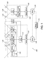
- FIG. 1 is a block diagram of an embodiment of the system 100 of the invention. This embodiment is comprised of a wearable data acquisition and display device 102 combined with an optical tracking system 104.
- the optical tracking system 104 has the ability to track items that are associated with passive beacons 128 as such items move throughout a facility.
- Components of the data acquisition and display device 102 are adapted to attach to a set of frames, lenses, shields, goggles, etc. (hereinafter generically referred to as "goggles") 106, which provides the ability to superimpose information about items that are being tracked proximately about or over the real objects (i.e., tracked items) that are within the goggle wearer's field of view. This is because the optical tracking system 104 tracks positional information about items or objects that have passive beacons 128 associated with such items. This tracking occurs through the use of fixed cameras 108 and a PBLT computer 110. The item tracking information is provided to the data acquisition and display device 102.
- the data acquisition and display device 102 has a local computer 112 that calculates the wearer's position and orientation. This is accomplished through the use of active beacons 114 that have known, fixed locations and unique "signatures" and a beacon detection device 116 such as, for example, a beacon camera and inertial sensor that comprise components of the data acquisition and display device 102.
- the local computer 112 knows the location of the fixed active beacons 114 and from the active beacons 114 that are in the beacon detection device's 116 field of view (FOV) is able to determine a wearer's position and orientation.
- Information about tracked items is provided to the local computer 112 from the optical tracking system 104 via one or more networks 120 and network interfaces 122. Therefore, certain information about tracked items that are in the wearer's field of view can be displayed on a see-through display 118. This information may appear to be superimposed proximately about or on the actual item because of the see-through feature of the display 118.
- the information displayed on the see-through display 118 about the tracked item is determined by business applications 124 that interface with both, the data acquisition and display device 102 and the optical tracking system 104 via the networks 120.
- these business applications 124 may cause sorting and loading instructions to appear on the items so that wearer's of the data acquisition and display device 102 do not have to read each item's label or have to read instructions provided by nearby screens, panels, CRTs, etc.
- Information about the tracked items may be obtained by an information gathering device 126 such as, for example, an image camera that obtains an image of the item's label and registers the item for tracking by the optical tracking system 104.
- the label image may be provided to the local computer 112 from the image device 126, where it is decoded and provided to the business applications 124 via the networks 120.
- the business applications 124 may combine the label data with other information and indicate to the local computer 112 what information is to be displayed in the see-through display 118.
- the information about the tracked items may be obtained by an information gathering device 126 such as, for example, a radio frequency identification (RFID) reader.
- the item's label may be an RFID tag.
- the information gathering device 126 obtains information from an item's label and registers the item for tracking by the optical tracking system 104.
- the label information may be provided to the local computer 112 from the information gathering device 126, where it is decoded and provided to the business applications 124 via the networks 120.
- the business applications 124 may combine the label data with other information and indicate to the local computer 112 what information is to be displayed in the see-through display 118.
- tracking systems may be utilized.
- a tracking system that tracks RFID tags by the use of fixed RFID readers may be used in place of an optical tracking system.
- FIG. 2 shows an embodiment of an exemplary data acquisition and display device 200.
- the embodiment of the data acquisition and display device 200 shown in FIG. 2 is comprised of five components, a set of frames or goggle 202, a see-through display 204, an information gathering device such as an image camera 206, a beacon detection device and orientation sensor 208, and a local computer 210 having a network interface (not shown).
- the see-through display 204 may be, for example, the MicroOptic SV-3 VIEWER TM as is available from The MicroOptical Corporation of Westwood, Massachusetts, or similar devices as are available from Tek Gear, Inc. of Winnipeg, Manitoba, Kaiser, or Electro-Optics, Inc. of Carlsbad, California, among others.
- the see-through display 204 is used to display superimposed objects in the line-of-sight of real objects.
- the see-through display 204 should have a resolution sufficient to view the superimposed objects without causing excessive eye fatigue.
- the resolution of the see-through display 204 may be, for example, a pixel format of 640 columns x 480 rows and have a FOV of at least 75 degrees.
- the see-through display 204 may be either monochrome or color.
- the display may be a device separate from the goggle through which the items may be viewed or, in other embodiments, on which a representation of the item may be viewed wherein such representation may include outline images of the items, symbols that represents the items or characteristic information about the items.
- the beacon detection device 208 is a camera attached to the goggles 202 and is used to acquire active beacons 114 (for determining the position and orientation of a wearer), and to acquire passive beacons that are in the wearer's field of view.
- the beacon detection device 208 is a beacon camera that is comprised of a wide-view (approximately 90° FOV) narrow band camera and orientation sensor. The beacon detection device 208 is used to acquire beacons (both active and passive) and the orientation sensor is used to track the orientation of the wearer.
- the information gathering device is an image camera 206 that is mounted on the goggle 202.
- the image camera 206 in one embodiment, is a center-view visible light camera that is used to acquire label images.
- the center-view visible light camera (a/k/a the image camera) 206 is used to acquire images and facilitate the registration of these images with a passive beacon.
- the image camera 206 may be separate from the goggle 202.
- the image camera 206 will have a depth of field that is fixed at about 12 inches to 30 inches and a FOV of about 28 degrees.
- the resolution of the image camera 206 in one embodiment is about 1500 x 1500 (2.25 million pixels).
- An image frame capture sequence for the image camera 206 is triggered by the discovery of a passive beacon in a close-proximity target zone.
- the image camera 206 may capture up to 1000 images per hour.
- the goggles 202 should provide the wearer with a sufficient FOV such that the wearer does not have to continuously move their head back and forth.
- this FOV is provided by goggles 202 having at least a 75 degree FOV, although other degrees of FOV may be used.
- the local computer 210 is comprised of a computer and network interface (not shown) that determine the orientation and position determination of the wearer from images obtained from the beacon detection device and orientation sensors 208.
- the local computer 210 also performs view-plane computations, which is a process that uses the three-dimensional position data for each relevant object, and determines the position and orientation of the wearer of the data acquisition and display device 200.
- the local computer 210 manages the application-provided display symbology for each relevant object to determine what is to be displayed in the see-through display 204 and where to display the information such that it appears superimposed proximately about or on the item.
- the local computer 210 performs close-proximity passive beacon discovery and registration, information processing such as image capture from the image capture camera 206, calibration of the beacon detection device 208 and image camera 206 with the see-through display 204, calibration of active beacons 114 relative to fixed cameras 108, communications (generally, wireless), and machine-readable codes decoding, which is a capability that significantly reduces the response time for displaying information on already-registered objects.
- the system 100 has ready to display information on an object and the object becomes obscured for a while and then re-appears; the user re-registers the object and quickly sees the relevant information; on-board decoding avoids the time to transfer the image across the communications network 120 to the business applications 124 for determination of display information.
- the local computer 210 may be a 250 MHz low power consumption CPU.
- the local computer 210 packaging may also contain a power source (not shown), which may be self-contained such as, for example, batteries or other forms of rechargeable, replaceable, reusable or renewable power sources.
- a power source (not shown), which may be self-contained such as, for example, batteries or other forms of rechargeable, replaceable, reusable or renewable power sources.
- the power source is 10-volt, 3 amp-hour battery.
- FIG. 3 is an embodiment of the data acquisition and display device 302 as shown on a wearer 304. As shown in the embodiment of FIG. 3 , the data acquisition and display device 302 is comprised of a see-through display 306 that is attached to or incorporated into a set of frames or goggles 308, and one or more information gathering devices such as cameras, and orientation sensors 310 attached to the frames 308.
- the frames 308 are head-mounted on a wearer 304, similar to a pair of glasses or goggles.
- a local computer 312 communicates with the see-through display 306, information gathering devices, and orientation sensors 310, optical tracking system 104, and business applications 124 over one or more networks.
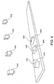
- FIG. 4 is an exemplary diagram of the use of fixed detectors fixed cameras in a passive beacon location tracking application in an embodiment of the invention.
- the fixed detectors such as, for example, fixed cameras 402 are mounted at fixed positions in the vicinity of the objects of interest 404.
- the purpose of these fixed cameras 402 is to continuously provide images to the process that computes the current location of each object of interest (a/k/a "items") 404.
- the objects of interest 404 may be singulated (as shown), or non-singulated.
- Each object of interest 404 is associated with at least one passive beacon 406.
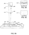
- FIG. 5C is an exemplary diagram of the use of fixed detectors such as, for example, fixed cameras 504 in a passive beacon location tracking application in an embodiment of the invention and having more detail than FIG. 4 .
- an energy source such as, for example, a light source 502 is attached to each fixed camera 504 and aimed along the image path 506.
- the light source 502 is generally not visible to the human eye (e.g., infrared), although in other embodiments other visible or non-visible light sources may be used such as, for example, lasers, colors or colored lights, ultraviolet light, etc.
- the lens 508 of the camera 504, in one embodiment as shown in FIG. 5C is covered with a filter 510 that is matched to the frequency of the light source 502.
- the purpose of the light source 502 and filter 510 is to provide an image 512 that only shows passive beacons 514 that are attached to or associated with each singulated or non-singulated item of interest 516, as shown by the images 512, 518 of FIGS. 5C and 5B , respectively.
- the fixed cameras 504 are low-cost, webcam type cameras having a resolution of about 640 x 480 pixels.
- FIG. 6 is an exemplary illustration of the use of active beacons 602 for determining the position and orientation of a wearer 304 of a data acquisition and display device 102 in an embodiment of the invention.
- the active beacons 602 provide a reckoning reference for the local computer 112 to determine the position and orientation of a user wearing the device 102.
- the active beacons 602 are sources of blinking light that are each uniquely recognized by the beacon detection device 116 of the data acquisition and display device 102.
- the active beacon 602 may be any source of unique magnetic, electrical, electronic, acoustical, optical transmission that are recognizable by the beacon detection device 116 of the data acquisition and display device 102.
- Each active beacon 602 has a relative fixed position 604 such as, for example, three-dimensional coordinates x, y, and z.
- the relative fixed position 604 of each active beacon 602 is known to the local computer 112, therefore the relative position and orientation of a wearer of the data acquisition and display device 102 may be computed by the local computer 112 by determining which active beacons 602 are in the FOV of the beacon detection device 116 of the data acquisition and display device 102.
- the energy source of the active beacon 602 is infrared light, although other visible or non-visible sources may be used such as lasers, colors or colored lights, ultraviolet light, etc.
- each active beacon 602 may use unique non-optical signals such as, for example, electronic transmissions, acoustical, magnetic, or other means of providing a unique signal for determining the orientation and position of the wearer 304.
- each active beacon 602 is uniquely identified by a blinking pattern that differentiates each active beacon 602 from other light sources and from other active beacons.
- each active beacon 602 transmits a repeating 11-bit unique identification pattern. This pattern consists of a 3-bit preamble followed by an 8-bit ID value. For instance, the preamble may be "001" and the ID value may be one of 88 values that do not begin with or contain the string "001.”
- Each pattern bit is split into two transmit bits. The state of the transmit bit determines whether the beacon is on or off.
- the value of the transmit bits are determined using a standard technique called “alternate mark inversion” or AMI.
- AMI is used to ensure that the beacon has a reliable blink rate.
- AMI is generally encoded whereby a "0" information bit becomes “01” and a "1" information bit alternates between "11” and "00.”
- each active beacon 602 is about 220 milliseconds or 440 milliseconds.
- the beacon detection device 116 of this embodiment is able to isolate beacon 602 blinkers from background noise by filtering out all light sources that do not have the given frequency.
- FIG. 7 is an exemplary illustration of the use of passive beacons 702 in an embodiment of the invention, as such passive beacons 702 are used for the tracking of items 704.
- the passive beacon 702 is intended to be a low-cost item that is attached to or associated with each item of interest 704. Its purpose is to provide a registration trigger for each item 704 and to provide a reference point to aid in three-dimensional position tracking from image data, as obtained from the fixed cameras 504.
- the passive beacon 702 is a use-once, adhesive light reflector, such as retro-reflective dots available from 3M of St. Paul, Minnesota. Retro-reflection causes light from a certain location to be reflected back, without extensive scattering, to the source of the light.
- each fixed camera 504 (previously described - see FIG. 5A ) is reflected back to the fixed camera 504. Because most other extraneous sources of light (noise) will be from sources less-reflective than the retro-reflective dots, the image viewed by the fixed camera 504 will be easily processed to eliminate most shapes except for the passive beacons 702. Generally, a passive beacon 702 having a diameter of approximately one-half inch will provide the resolution necessary for the fixed cameras 504 at a reasonable range.
- the passive beacon may be an RFID tag located on or associated with the item.
- a modulated RFID signal is returned from the RFID tag passive beacon when a certain RF signal is present.
- a passive beacon overcomes challenges associated with passive beacons that must maintain a certain orientation toward a detector. For instance, an RFID passive beacon could continue to be tracked if the item is flipped over or if it passes under some obstructions.
- United States patent number 6,661,335 describes a system and method for tracking a RFID transponder relative to a sensor (e.g., fixed detector).
- the process involved in the optical tracking system knowing the position of the passive beacons 702 is two-part; passive beacon registration and passive beacon tracking.
- Passive beacon tracking occurs once a passive beacon 806 has been detected by two or more fixed detectors such as, for example, fixed cameras 804, 804a.
- the three-dimensional computed position 802 of the passive beacon 806 is determined from knowing the position and orientation of each fixed camera 804, 804a.
- the passive beacon location tracking system 110 computes the passive beacon's position from two-dimensional images ( FIGS. 8B and 8C ) from the fixed cameras 804, 804a that are interpolated to be synchronized in time that track the position of passive beacon 806 relative to the location 808, 808a of each of the fixed cameras 804, 804a.
- the passive beacon location tracking system 110 should keep track of a passive beacon 802 during periods of intermittent disappearance and when the passive beacons 802 are visible to only one fixed camera 804 to provide consistent tracking. Two fixed cameras 804 first acquire a passive beacon 802 to initially determine the passive beacon's location, but a "lock" is maintained while the passive beacon 802 is visible to only one fixed camera 804.
- the passive beacon location tracking system 110 makes assumptions about the passive beacon's motion that enable the lock to be maintained during times of disappearance. For example, streams of passive beacons associated with items flowing along on a conveyor system (as shown in FIGS. 5A and 5C ) have a high likelihood of not flowing backward.
- the probable trajectory of the passive beacon 802 is used by an algorithm of the passive beacon location tracking system 110 to track the unobserved passive beacon 802. It may also be possible to track passive beacons 802 flowing under a conveyor over-pass by observing continuous flow. However, when a passive beacon 802 falls out of view of all fixed cameras 804 for a significant period of time, the passive beacon location tracking system 110 loses the item and it (the passive beacon 802) is essentially gone from the perspective of the passive beacon location tracking system 110.
- FIGS. 9 and 10 provide exemplary illustrations of the concept of passive beacon registration, in an embodiment of the invention.
- Passive beacon registration occurs when a passive beacon is being detected simultaneously by two or more fixed detectors and the passive beacon location tracking system 110 declares that the passive beacon is discovered.
- the passive beacon location tracking system discovers a passive beacon when a prominent reflection (generally, an infrared reflection) "winks" at the beacon detection device 116 (in this instance, a beacon camera).
- a person wearing a data acquisition and display device 102 has obtained an item 902 and has placed a retro-reflective dot (i.e., a passive beacon) 904 on the item 902.
- a retro-reflective dot i.e., a passive beacon
- the passive beacon 904 is not visible as it is underneath the person's thumb.
- the person has moved their thumb, thereby exposing the passive beacon 904, and causing a "wink.”
- the "wink” is a sudden long-duration (greater than approximately one-half second) steady reflection from the passive beacon 904.
- the "wink” is also observed by the fixed cameras 108 of the optical tracking system 110.
- the local computer 112 of the data acquisition and display device 102 assigns the newly-acquired passive beacon 904 a unique handle.
- the data acquisition and display device 102 notifies the passive beacon location tracking system 110 of the passive beacon 904 discovery and its handle, as well as the approximate location of the discovered passive beacon 904.
- the passive beacon location tracking system 110 relates the discovered passive beacon's handle to the tracked passive beacon that was observed to "wink” at the fixed cameras 108.
- the optical tracking system 104 acknowledges the lock-on of the passive beacon 904 to the data acquisition and display device 102, allowing the data acquisition and display device 102 to provide positive feedback of tracking to the wearer.
- the optical tracking system 110 publishes, and continually updates, the three-dimensional position of the passive beacon 904 relative to the passive beacon's 904 given unique handle.
- the "winking" process may be performed by mechanical shutters between the passive beacon and the fixed cameras 108 and/or image device 206, by adjusting the apertures of the cameras 108, 206, or by "self-winking" or blinking passive beacons 904.
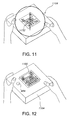
- FIGS. 11 and 12 illustrate the concept of acquiring item information (e.g., label information) in an embodiment of the invention.
- the information gathering device is an image camera 206.
- the image camera 206 of this embodiment of the data acquisition and display system 200 acquires the image 1102 from the item 1104.
- the local computer 210 of the data acquisition and display device 200 receives the image 1102 from the image camera 206 and decodes machine-readable codes (e.g., barcodes, etc.) from the image and passes the image 1102 and decoded information for the related passive beacon handle to any associated business applications 124.
- machine-readable codes e.g., barcodes, etc.
- These business applications 124 assign relevant displayable information that will be presented to designated wearers of a data acquisition and display device 200 when the passive beacon's 904 three-dimensional position is within the see-through display's 204 field of view and within range.
- the "label" is an RFID tag and the information gathering device 126 is an RFID reader.
- the item information may be acquired by fixed devices or devices separate from the data acquisition and display device, as such devices are known in the art. In the particular embodiment of FIG. 11 , an image of the acquired information 1102 is displayed on or proximate to the item 1104 to verify acquisition of the information.
- the local computer 112 uses real-time information derived from the beacon detection device 116 to determine orientation and position of the data acquisition and display device 102, and thus any wearer of the device 102, relative to the active beacons 114.
- the orientation information derived from the beacon detection device 116 is augmented by highly responsive inertial three degrees-of-freedom (DOF) rotational sensors (not shown separately from 116).
- DOE degrees-of-freedom
- the orientation information is comprised of active beacon IDs and active beacon two-dimensional image position from the beacon detection device 116. Additional information that is needed includes the active beacons' three-dimensional reference locations versus the active beacons' IDs.
- Multiple active beacons 114 are used to determine the data acquisition and display device's 102 orientation and position. The more active beacons 114 used to compute orientation and position, the greater the accuracy of the measurement. Also, it may be possible that a particular active beacon ID value is used for more than one active beacon in a particular facility. Therefore, the data acquisition and display device 102 must be able to discard position values that are non-determinant (i.e., non-solvable positions from beacon images).
- the tracking design must accurately assume the identification of each active beacon 114 for each updated image capture frame. Once an active beacon 114 is identified, the data acquisition and display device 102 must "lock-on"" and track its motion (as caused by movement of the wearer) in the two-dimensional image plane.
- the known unique blink or transmission rate, pattern or signal of the active beacons 114 allows the image processor to remove most energy sources from the image that are not active beacons 114 by use of a filter such as, for example, a narrow-pass filter.
- the remaining active beacons are identified after observing a complete ID cycle (previously described).
- the extrapolated two-dimensional position of each identified active beacon 114 is input into the three-dimensional position and orientation computation process.
- inertial sensors in combination with the beacon detection device 116, may be used in these instances to determine head orientation.
- Inertial navigation technology uses semiconductor-sized micro-machined accelerometers to detect rotation. Such devices are commercially available from manufacturers such as, for example, InterSense, Inc. of Burlington, Massachusetts, among others.
- the inertial navigation sensors may replace or supplement the active beacon 114 orientation signal during times of rapid head movement.
- the process of installing fixed detectors such as, for example, fixed cameras 108 and establishing their known position in relation to other fixed cameras 108 is a multi-step process whereby multiple fixed cameras 108 observe the same object and learn their position and orientation relative to one another.
- the process begins with Step 1300.
- the first and second fixed detectors to be calibrated are chosen because they are installed adjacent (with a normal separation distance for tracking) to each other.
- the tracking system 104 is placed into calibration mode for the two fixed detectors of interest.
- Step 1306 a passive beacon 904 is placed within view of both fixed detectors and the passive beacon is covered or blocked and uncovered several times so as to cause a "winking" effect, thus causing the tracking system 104 to calculate the possible positions and orientations of both fixed detectors relative to one another.
- the passive beacon 904 is repositioned to a different location within view of both fixed detectors and the "winking" procedure of Step 1306 is repeated.
- the passive beacon repositioning/winking process is repeated until the tracking system 104 indicates that a single unique position is known for each fixed detector, which may take between two and four iterations of the repositioning/winking process.
- Step 1310 the third through the remaining fixed detectors are calibrated in a similar repositioning/winking process until all fixed detectors are calibrated. If a fixed detector will not calibrate during the repositioning/winking process, it may be installed incorrectly and need to be re-installed or repaired.
- the process ends at Step 1312. When a new fixed detector is installed or an old fixed detector is moved, the repositioning/winking process is performed so that the detector's new position is learned relative to the calibrated adjacent detectors.
- the data acquisition and display device 200 is calibrated so that the alignment between the devices of the data acquisition and display device 200 is known. It is assumed that normal manufacturing tolerances and routine use will result in some amount of mis-alignment of the active beacon detection device 208, information gathering device such as an image camera 206, and the see-through display 204. These devices require concurrent alignment for better operational characteristics of the data acquisition and display device 200.
- the procedure requires first placing the data acquisition and display device 200 into calibration mode by aiming the image camera 206 at a special pattern or barcode. A crosshair pattern is then displayed on the see-through display 204 and the crosshairs are aimed at the special calibration pattern.
- the see-through display 204 will then ask for successive trials of aiming the crosshairs of the see-through display 204 until the data acquisition and display device 200 is able to isolate the needed precision in the alignment compensation for the imaging camera 206, beacon detection device 208, and the see-through display 204. This calibration information will be retained by the data acquisition and display device 200 until the next calibration mode process.
- each active beacon 114 relative to the fixed detectors such as, for example, fixed cameras 108, must be known so that the data acquisition and display device 102 can determine the position and orientation of a wearer relative to the active beacons 114.
- the calibration process begins by attaching an active beacon 114 to the side of each of three calibrated and adjacent fixed cameras 108 or by having three active beacons 114 with known locations. The positions of these active beacons are now known from the positions of the fixed cameras 108.
- a fourth active beacon 114 is placed anywhere within the field of view of the beacon detection device 116 along with the three initially placed active beacons 114 having known locations.
- the wearer With a calibrated data acquisition and display device 102 that has been placed in its active beacon calibration mode, the wearer aims the crosshairs displayed in the see-through display 118 at the fourth active beacon 114. The wearer is then prompted to reposition the data acquisition and display device 102 (while still maintaining the three active beacons 114 with known locations and the fourth active beacon 114 in the field of view of the beacon detection device 116) several times until a location for the fourth active beacon 114 is computed by the local computer 112. This process is repeated as active beacons 114 are added throughout the facility. Anytime a new or moved active beacon 114 is installed, this aiming and calibration process with a data acquisition and display device 102 will determine the relative location of the active beacon 114.
- the installer of the active beacon 114 chooses the physical ID values for each active beacon 114.
- the installer should not use equivalent IDs on active beacons 114 that are adjacent to a common active beacon 114.
- One way to prevent this is to section the facility off into repeating 3 x 3 grid zones, zones "a" through “i.” All active beacons 114 installed in an "a" zone are assigned an ID from a pre-determined "a" set of IDs, all active beacons installed in an "b” zone are assigned an ID from a pre-determined "b” set of IDs, etc.
- the size of each zone is a function of the number of active beacons 114 that may be maximally required in each zone.
- the 3 x 3 grid is repeated throughout the facility as often as needed.
- Each active beacon 114 in an installation has a unique logical ID value (previously described) that is assigned to the combination of a physical ID value and a three-dimensional position.
- the active beacon installation process produces and assigns the logical ID value.
- the optical tracking system 1402 of this embodiment is designed to be as self-contained as possible.
- a passive beacon location tracking ("PBLT") computer 1404 accepts all fixed camera 1406 images and, with the known relative position and orientation of the fixed cameras 1406, uses the images to determine the three-dimensional location of each tracked passive beacon 1408.
- PBLT passive beacon location tracking
- the optical tracking system 1402 is comprised of one or more inputs from an information gathering device 1412 of one or more data acquisition and display devices 1410 that cue the registration of a passive beacon 1408 for tracking; the fixed cameras 1406 from which the PBLT 1404 reads all images from each fixed camera 1406; a fixed camera locations repository 1414 that contains each fixed camera's logical ID, position and orientation and is used to calculate the positions of all tracked passive beacons 1408, and is updated when the PBLT 1404 is in fixed camera installation mode; object location repository 1416, which stores the location of each passive beacon (or item) 1408 by the item's logical ID (may be accessed by business applications); and, a maintenance console (not shown in FIG.
- the passive beacons 1408 are generally associated with items (e.g., parcels) 1432, so that the items may be tracked.
- the optical tracking system 1402 is capable of providing information to other business applications 1418.
- the business application receives an item's logical ID and decoded label information of the item from the data acquisition and display device 1410.
- the business application 1418 converts the label information into display information and publishes the information to a data repository 1420 that contains object ID information and associated display information.
- this information can be provided to a data acquisition and display device 1410 that, by knowing its position and orientation as determined by an orientation computation process of the local computer 1422, the display information can be displayed on the see-through display 1424 such that it is properly associated with the object.
- the orientation computation process involves accessing an active beacons location database 1426 containing the know locations of active beacons 1428 and a unique identifier assigned to each active beacon 1428 such that when a wearer of a data acquisition and display device 1410 detects certain active beacons 1428 by their assigned identifier with the data acquisition and display device's beacon detection device 1430, the local computer is able to compute the orientation and position of the data acquisition and display device 1410.
- the business application 1418 receives images of objects and converts the images into display information.
- the business application 1418 receives a logical ID value for the data acquisition and display device 1410 that provided the information, along with decoded label data. If the decoded label data is of the type that is application-defined to represent a job indicator, then the business application 1418 is able to discern which data acquisition and display device 1410 is assigned to each job type and display information is provided to only this data acquisition and display devices 1410. Finally, the business application 1418 receives an item's logical ID along with the item's position from the optical tracking system 1402. The business application 1418 uses the position information to determine the status of certain items, project processing times, measure throughput of items in a facility, and make other business decisions.
- An exemplary method of applying an embodiment of the system of the present invention is its use in a parcel sorting facility as shown in FIG. 15 .
- a data acquirer (“Acquirer”) 1502 and a parcel sorter (“Sorter”) 1504 wear and use a data acquisition and display device 200 in the performance of their duties.
- the step of acquiring item information may be performed by devices not connected to a data acquisition and display device 200 such as by an over-the-belt scanning system, as are known in the art.
- Others, such as supervisors and exception handlers may also wear a data acquisition and display device 200, but those persons are not described in this particular example.
- the Acquirer 1502 and Sorter 1504 each don a data acquisition and display device 200, power it up, and aim the information gathering device such as, for example, an image camera 206 at a special job set-up indicia, pattern, or barcode that is application defined.
- the chosen business application as selected by the job set-up indicia, is notified by each data acquisition and display device 200 of the initialization and job set-up. The business application thus becomes aware of the data acquisition and display devices 200 that are participating in each job area.
- the Acquirer 1502 is positioned near the parcel container unload area 1506 of the facility and images the shipping label of each parcel 1508. As shown in FIG. 16 , the Acquirer 1502 aims a target 1602 that is displayed in the see-through display 204 of the data acquisition and display device 200 and places a passive beacon such as, for example, an adhesive reflective passive beacon 1604 near the label 1606. The passive beacon 1604 is covered and uncovered thereby "winking" the passive beacon 1604 at the beacon detection device 208 of the data acquisition and display device 200 and triggering the capture of the label image by the image camera 206. In other embodiments (not shown), label information may be captured by over-the-belt label readers or other such devices, as they are known in the art.
- the optical tracking system 1402 detects the appearance of a passive beacon 1604 through the fixed detectors such as, for example, the fixed cameras 108 and receives a notification event from a data acquisition and display device 200 that assigns a logical ID value to the passive beacon 1604.
- the optical tracking system 1402 begins tracking the passive beacon 1604 and sends a track lock-on acknowledgement to the data acquisition and display device 200.
- a high-contrast copy of the captured image 1704 is displayed in the Acquirer's 1502 see-through display 204 to indicate that the label information has been captured. If the captured image 1704 appears fuzzy, distorted, or otherwise unclear, the Acquirer 1502 may re-capture the image 1704.
- the see-through display 204 of the data acquisition and display device 200 will also display a confirmation to the Acquirer 1502 that the tracking process for the item has begun and that the Acquirer 1502 may move on to the next parcel. If the Acquirer 1502 does not receive the confirmation or if the images need to be re-captured, then the passive beacon 1604 should once again be "winked” in order to repeat the acquisition cycle. If confirmation is received and the image does not need to be re-captured, the item is placed on a conveyor system 1512 with the passive beacon 1604 facing the fixed cameras 108.
- the business application uses the decoded label data acquired from the image to determine appropriate handling instructions for each parcel 1508. If the label has insufficient coded data, then the image from the label is transferred to a key-entry workstation. Using the label image, the key-entry personnel will gather the information needed to handle the package.
- Each Sorter 1504 wearing a data acquisition and display device 200 has a defined field of view (FOV) 1510, as shown in FIG. 15 .
- FOV field of view
- the Sorter 1504 will see that package's 1802 super-imposed handling instructions 1804 proximately floating over or about the packages 1802 that are allocated to that Sorter 1504.
- the Sorter 1504 will load each of these packages 1508 according to the super-imposed handling instructions 1804.
- tracked packages 1508 on the conveyor 1512 that have somehow lost their handling instructions have a special indicator (not shown) imposed on them and can be re-registered by "winking" their passive beacon 1604 thus causing the super-imposed handling instructions 1804 to appear to wearers of a data acquisition and display device 200.
- tracked packages 1508 that are not allocated to the immediate area of a Sorter 1504 have a special symbol (not shown) super-imposed on them. This indicates that the package is being tracked, but that it is not for loading in that Sorter's 1504 immediate area.
- packages that have no handling instructions or special symbol associated with them provides indication that the package was never registered by the Acquirer 1502 or that the package has been flipped or otherwise lost its passive beacon 1604.
- parcel information is displayed sequentially as each package 1508 enters a Sorter's 1504 field of view 1510 or work area, whereas in other embodiments information is displayed for all parcels 1508 within the Sorter's 1504 field of view 1510 or work area.
- the parcels 1508 may be singulated or non-singulated.
- FIG. 19 is a flowchart describing the steps for a method of processing an item in an embodiment of the invention.
- the steps include beginning the process at Step 1900.
- Step 1902 an item is viewed while wearing a data acquisition and display device having a see-through display.
- Step 1904 involves displaying processing instructions on the see-through display in a manner such that the processing instructions appear proximately superimposed on the item.
- Step 1906 the items are processed in accordance with the processing instructions.
- the process ends at Step 1908.
- Such a process as described in FIG. 19 may be used for the processing of mail and parcels, among other uses.
- FIG. 20 is also a flowchart describing the steps for a method of processing an item in another embodiment of the invention.
- the process of FIG. 20 begins at Step 2000.
- an item is tracked with a tracking system as the item's location changes.
- the orientation and position of a wearer of a data acquisition and display device having a see-through display is determined.
- it is determined which items are in the field of view of the see-through display of the data acquisition and display device.
- Step 2008 an item is viewed through the see-through display of the data acquisition and display device.
- processing instructions relevant to the item are displayed on the see-through display in a manner such that the processing instructions appear proximately superimposed on the item.
- Step 2012 the item is processed in accordance with the processing instructions.
- the process ends at Step 2014.
- FIG. 21 is a flowchart describing a method of displaying information about one or more items in a see-through display of a data acquisition and display device in an embodiment of the invention.
- the process begins at Step 2100.
- Step 2102 orientation and position information about a wearer of the data acquisition and display device is captured.
- Step 2104 a field of view of the see-through display is determined from the captured orientation and position information.
- Step 2106 information is displayed on the see-through display about the items in the field of view of the see-through display such that the information appears to be proximately superimposed on the items when the items are viewed through the see-through display.
- the process ends at Step 2108.
- Such a process as described in FIG. 21 may be used for the processing of mail and parcels, among other uses.
- FIG. 22 is a flowchart that describes a method of displaying information in a see-through display of a data acquisition and display device in another embodiment of the invention.
- the process begins at Step 2200.
- data about an item is captured by, for example, an information gathering device such as the image device 126.
- information and instructions about the item are determined from the captured data.
- orientation and position information about a wearer of the data acquisition and display device is captured by, for example, the beacon detection device 116.
- Step 2208 a field of view of the see-through display of the data acquisition and display device is determined from the captured orientation and position information.
- Step 2210 information and instructions are displayed on the see-through display about the item in the field of view of see-through display such that the information and instructions appear to be proximately superimposed on the item when the item is viewed through the see-through display.
- the process ends at Step 2212.
- FIG. 23 is a flowchart describing a method of optically tracking one or more items in an embodiment of the invention.
- the process begins at Step 2300.
- a source of energy such as, for example, a light, magnetic waves, electronic transmission, etc. is provided.
- a passive beacon such as, for example, a retro-reflective dot or other shape comprised or retro-reflective material is placed on or associated with an item. The passive beacon is activated by the source of energy or said beacon reflects energy from the source of energy.
- Step 2306 two or more fixed detectors such as, for example, fixed cameras having known fixed locations relative to one another are provided with each fixed camera having a defined field of view and capable of detecting energy transmitted or reflected from the passive beacon if the passive beacon is in the fixed camera's field of view.
- Step 2308 the location of the passive beacon is computed from the energy received by the two or more fixed cameras from the passive beacon as the location of the item changes.
- the process ends at Step 2310.
- the process as described above may be used for the optical tracking of mail and parcels, among other uses.
- FIG. 24 is a flowchart describing a method of optically tracking one or more items in another embodiment of the invention.
- the process begins at Step 2400.
- a source of energy such as, for example, a light, magnetic waves, electronic transmission, etc. is provided.
- a passive beacon such as, for example, a retro-reflective dot or other shape comprised or retro-reflective material is placed on an item. The passive beacon is activated by the source of energy or said beacon reflects energy from the source of energy.
- Step 2406 two or more fixed detectors such as, for example, fixed cameras having known fixed locations relative to one another are provided with each fixed camera having a defined field of view and capable of detecting energy transmitted or reflected from the passive beacon if the passive beacon is in the fixed camera's field of view.
- Step 2408 the location of the passive beacon is computed from the energy received by the two or more fixed cameras from the passive beacon as the location of the item changes.
- Step 2410 a data acquisition and display device having a see-through display, an image device such as, for example, an image camera or an RFID reader, a local computer, and a beacon detection device such as, for example, a beacon camera, is provided.
- image data about the item is captured with the image device.
- the image data may be, for example, a mailing label having both machine-readable and human-readable elements, or an RFID tag, or a combination thereof.
- information about the item is determined from the image data with the local computer.
- orientation and position information about the data acquisition and display device is captured with the beacon detection device.
- a field of view of the see-through display is determined from the captured orientation and position information.
- Step 2422 information and instructions are displayed on the see-through display about the item if the item is in the field of view of see-through display such that the information and instructions appear to be proximately superimposed on the item when the item is viewed through the see-through display.
- the process ends at Step 2424.
- FIG. 25 is a flowchart describing a method of tracking items in an embodiment of the invention.
- the process begins with Step 2500.
- a data acquisition and display device having an information gathering device to capture data about an item is provided.
- the information gathering device may be, for example, an image camera, an RFID reader, etc.
- the captured data may come from a mailing label and/or an RFID tag.
- an active beacon detection device to capture orientation and position information about a wearer of the data acquisition and display device, a see-through display to display information and instructions about the item, and a local computer in communication with the information gathering device, active beacon detection device, and see-through display.
- the local computer decodes data from the information gathering device, computes the orientation and position of the wearer of the data acquisition and display device from the orientation and position information captured by the active beacon detection device, and provides information and instructions to be displayed in the see-through display about items in the field of view of the data acquisition and display device.
- a tracking system is provided.
- the tracking system is comprised of a source of energy such as, for example, a light.
- a passive beacon such as, for example, a retro-reflective dot or an RFID tag is located on or associated with the item that is activated by the source of energy or the passive beacon reflects energy from the source of energy.
- Two or more fixed detectors are provided with each having a defined field of view that are each capable of detecting energy transmitted or reflected from the passive beacon if the passive beacon is in the fixed detector's field of view.
- a passive beacon location tracking computer is in communication with the two or more fixed detectors. The passive beacon location tracking computer knows the location of each fixed detector relative to the other fixed detectors and the passive beacon location tracking computer is able to compute the location of the passive beacon from the energy received by the two or more fixed detectors from the passive beacon as the location of the item changes.
- Step 2506 information about an item's location is provided to the local computer from the tracking system so that the local computer can determine what items are in the data acquisition and display device's field of view.
- Step 2508 information about those items in the field of view of the data acquisition and display device is displayed in the see-through display such that the instructions and information appear proximately superimposed on the items.
- the process ends at Step 2510.
- FIG. 26 is a flowchart that describes a method of computing the orientation and position of a wearer of a data acquisition and display device in an embodiment of the invention.
- the process begins at Step 2600.
- Step 2602 two or more unique active beacons having known locations relative to one another are provided.
- Step 2604 a data acquisition and display device having a beacon detection device with a defined field of view is provided.
- Step 2606 two or more unique active beacons within the beacon detection device's field of view are sensed by the beacon detection device.
- the location of the data acquisition and display device relative to the known location of the two or more unique active beacons within the field of view of the beacon detection device is determined.
- the process ends at Step 2610.
- Embodiments of the invention may be used in various applications in parcel and mail sorting and processing. For instance, in one embodiment, certain people with a sorting/processing facility may be able to see different information about items than what other wearers of a data acquisition and display device may be able to see. Examples include high-value indicators, hazardous material indicators, and items requiring special handling or adjustments. Security may also be facilitated by the use of embodiments of the system as items are constantly tracked and their whereabouts recorded by the tracking system as they move through a facility. And, as previously described, embodiments of the invention may be used to track item flow through a facility such that the flow may be enhanced or optimized.
- Embodiments of the invention may also be used in applications other than parcel or mail sorting and processing. Many applications involving queues and queuing may make use of embodiments of the system. For instance, air traffic controllers managing ground traffic at an airport may have information about flights superimposed proximately about or over the actual airplanes as they are observed by a controller wearing a data acquisition and display device. Similarly, train yard operators and truck dispatchers may have information about the trains or trucks, their contents, etc. displayed on the actual trains and/or trucks. Furthermore, sorting facilities other than mail and parcel sorting facilities may make use of the embodiments of the invention. For instance, embodiments of the invention may be used in the sorting of baggage at an airport whereby sorting instructions will be displayed to sorters wearing a data acquisition and display device.
- a wearer of a data acquisition and display device may be able to see instructions guiding them to a particular destination. Examples include libraries, warehouses, self-guided tours, large warehouse-type retail facilities, etc. Routine maintenance of apparatuses may be improved by having maintenance records appear to the wearer of a data acquisition and display device when the wearer looks at the device in question.
Landscapes
- Engineering & Computer Science (AREA)
- General Engineering & Computer Science (AREA)
- User Interface Of Digital Computer (AREA)
- Control Of Indicators Other Than Cathode Ray Tubes (AREA)
- Image Analysis (AREA)
- Saccharide Compounds (AREA)
- Polymers With Sulfur, Phosphorus Or Metals In The Main Chain (AREA)
Claims (11)
- Verfolgungsvorrichtung umfassend:eine Datenerfassungs- und Displayeinrichtung (102),einen Detektor (116) für optische Aktivmarkierungen, welcher Orientierungs- und Positionierungsinformationen über einen Träger der Datenerfassungs- und Displayeinrichtung (102) erfasst, indem er individuelle optische Signale von mindestens zwei Aktivmarkierungen (114) innerhalb eines Sichtfeldes des Detektors (116) für optische Aktivmarkierungen empfängt, wobei jede Aktivmarkierung einen bekannten, festen Ort und eine individuelle Signatur hat;ein Durchsichtsdisplay (118) mit einem definierten Sichtfeld; undein verfolgendes Passivmarkierungsort-Verfolgungssystem (110), welches zum Verfolgen konfiguriert ist, um den Ort von einem oder mehreren nicht-stationären Artikeln mit einer Passivmarkierung (128), welche unmittelbar an jedem der ein oder mehreren nicht-stationären Artikel angeordnet ist, zu verfolgen, indem das Verfolgungssystem (110)Energie einer Energiequelle empfängt, die von den Passivmarkierungen (128) reflektiert wird, undeinen Computer (112), der mit dem Detektor (116) für optische Aktivmarkierungen und dem Passivmarkierungsort-Verfolgungssystem (110) kommuniziert, und der konfiguriert ist, umaus der Orientierungs- und Positionsinformation des Trägers der Datenerfassungs- und Displayeinrichtung (102) und des definierten Sichtfeldes des Durchsichtsdisplays (118) zu bestimmen, welche, wenn überhaupt, der ein oder mehreren nicht-stationären Artikel mit jeweils einer Passivmarkierung unmittelbar daran im Sichtfeld des Durchsichtsdisplays (118) sind, undeine Anzeige der Informationen und Instruktionen über den einen oder mehrere nicht-stationäre Artikel mit jeweils einer Passivmarkierung (128) unmittelbar daran im Sichtfeld des Durchsichtsdisplays (118) zu erzeugen, wobei die Informationen und Instruktionen nahe überlagert auf mindestens einem der ein oder mehreren nicht-stationären Artikel erscheinen.
- Verfolgungsvorrichtung nach Anspruch 1, ferner umfassend:einen Inertialsensor, wobei der Inertialsensor Orientierungsinformationen der Datenerfassungs- und Displayeinrichtung (102) während ihrer Bewegung liefert.
- Verfolgungsvorrichtung nach Anspruch 1, ferner umfassend:eine Informationserfassungseinrichtung (206) zur Erfassung von Daten über einen oder mehrere Artikel.
- Verfolgungsvorrichtung nach Anspruch 3, wobei die Informationserfassungseinrichtung eine Bildkamera (206) umfasst.
- Verfolgungsvorrichtung nach Anspruch 3, wobei die Informationserfassungseinrichtung (206) einen RFID-Leser umfasst.
- Verfolgungsvorrichtung nach Anspruch 1, wobei der eine oder mehrere Artikel nicht vereinzelt sind.
- Verfolgungsvorrichtung nach Anspruch 1, wobei der eine oder mehrere Artikel vereinzelt sind.
- Verfahren zum Verfolgen eines oder mehrerer nicht-stationärer Artikel, umfassend:Bereitstellen einer Energiequelle;Orten einer Passivmarkierung (128) unmittelbar an einem oder mehreren nicht-stationären Artikeln, wobei die Passivmarkierung auf die Energiequelle reagiert;Vorsehen zweier oder mehrerer fester Detektoren mit bekannten festen Orten relativ zueinander, wobei jeder feste Detektor die von jeder Passivmarkierung (128) übertragene oder reflektierte Energie detektieren kann;Berechnen des Ortes jeder Passivmarkierung (128) aus der von den zwei oder mehreren festen Detektoren von jeder Passivmarkierung empfangenen Energie, wenn sich der Ort der ein oder mehreren nicht-stationären Artikel ändert;Vorsehen einer Verfolgungsvorrichtung, die eine Datenerfassungs-und Displayeinrichtung (102) mit einem Durchsichtsdisplay (118) umfasst, einer Informationserfassungseinrichtung (126), eines Rechengeräts (112) und eines Detektors (116) für optische Aktivmarkierungen;Erfassen von Daten über den einen oder mehrere nicht-stationäre Artikel mit der Informationserfassungseinrichtung (126);Bestimmen von Informationen über den einen oder mehrere nicht-stationäre Artikel aus den erfassten Daten mit der Erfassungseinrichtung;Erfassen der Orientierungs- und Positionsinformation über die Datenerfassungs- und Displayeinrichtung (102) mit dem Detektor (116) für optische Aktivmarkierungen durch Empfangen individueller optischer Signale von mindestens zwei Aktivmarkierungen innerhalb eines Sichtfeldes des Detektors (116) für optische Aktivmarkierungen, wobei jede Aktivmarkierung einen bekannten, festen Ort und eine individuelle Signatur hat;Bestimmen eines Sichtfeldes des Durchsichtsdisplays (118) aus den erfassten Orientierungs- und Positionsinformationen;Bestimmen, wenn mindestens einer der ein oder mehreren nicht-stationären Artikel innerhalb des Sichtfeldes des Durchsichtsdisplays (118) ist von dem Ort der Passivmarkierung aus; undAnzeigen der Informationen und Instruktionen auf dem Durchsichtsdisplay (118) über mindestens einen der ein oder mehreren nicht-stationären Artikel, wenn der eine oder mehrere nicht-stationäre Artikel im Sichtfeld des Durchsichtsdisplays (118) sind, derart, dass die Informationen und Instruktionen nahe überlagert auf dem einen oder der mehreren nicht-stationären Artikeln erscheinen, wenn der eine oder mehrere nicht-stationäre Artikel durch das Durchsichtsdisplay betrachtet werden.
- Verfahren nach Anspruch 8, wobei das Verfahren für die Verfolgung von Post und Paketen angewendet wird.
- Verfahren nach Anspruch 8, wobei das Erfassen von Daten über den einen oder mehrere nicht-stationäre Artikel mit der Informationserfassungseinrichtung (126) mittels einer Bildkamera (206) erfolgt.
- Verfahren nach Anspruch 8, wobei das Erfassen von Daten über den einen oder mehrere nicht-stationäre Artikel mit der Informationserfassungseinrichtung (126) mittels eines RFID-Lesers erfolgt.
Applications Claiming Priority (2)
| Application Number | Priority Date | Filing Date | Title |
|---|---|---|---|
| US10/763,440 US7063256B2 (en) | 2003-03-04 | 2004-01-23 | Item tracking and processing systems and methods |
| EP04815352A EP1706808B1 (de) | 2004-01-23 | 2004-12-20 | Postenverfolgungs- und verarbeitungssysteme und -verfahren |
Related Parent Applications (2)
| Application Number | Title | Priority Date | Filing Date |
|---|---|---|---|
| EP04815352A Division EP1706808B1 (de) | 2004-01-23 | 2004-12-20 | Postenverfolgungs- und verarbeitungssysteme und -verfahren |
| EP04815352.2 Division | 2004-12-20 |
Publications (3)
| Publication Number | Publication Date |
|---|---|
| EP2244162A2 EP2244162A2 (de) | 2010-10-27 |
| EP2244162A3 EP2244162A3 (de) | 2010-11-24 |
| EP2244162B1 true EP2244162B1 (de) | 2016-06-15 |
Family
ID=34826468
Family Applications (3)
| Application Number | Title | Priority Date | Filing Date |
|---|---|---|---|
| EP10172960.6A Expired - Lifetime EP2244162B1 (de) | 2004-01-23 | 2004-12-20 | Postenverfolgungs- und Verarbeitungssysteme und -verfahren |
| EP04815352A Expired - Lifetime EP1706808B1 (de) | 2004-01-23 | 2004-12-20 | Postenverfolgungs- und verarbeitungssysteme und -verfahren |
| EP10172959.8A Expired - Lifetime EP2244161B1 (de) | 2004-01-23 | 2004-12-20 | Postenverfolgungs- und Verarbeitungssysteme und -verfahren |
Family Applications After (2)
| Application Number | Title | Priority Date | Filing Date |
|---|---|---|---|
| EP04815352A Expired - Lifetime EP1706808B1 (de) | 2004-01-23 | 2004-12-20 | Postenverfolgungs- und verarbeitungssysteme und -verfahren |
| EP10172959.8A Expired - Lifetime EP2244161B1 (de) | 2004-01-23 | 2004-12-20 | Postenverfolgungs- und Verarbeitungssysteme und -verfahren |
Country Status (8)
| Country | Link |
|---|---|
| US (3) | US7063256B2 (de) |
| EP (3) | EP2244162B1 (de) |
| JP (1) | JP2007523811A (de) |
| CN (1) | CN100390709C (de) |
| AT (1) | ATE483192T1 (de) |
| CA (1) | CA2551146C (de) |
| DE (1) | DE602004029397D1 (de) |
| WO (1) | WO2005073830A2 (de) |
Families Citing this family (209)
| Publication number | Priority date | Publication date | Assignee | Title |
|---|---|---|---|---|
| WO2003098533A1 (en) * | 2002-05-16 | 2003-11-27 | United Parcel Service Of America, Inc. | Systems and methods for package sortation and delivery using radio frequency identification technology |
| US7310441B2 (en) * | 2003-04-11 | 2007-12-18 | Intel Corporation | Method and apparatus for three-dimensional tracking of infra-red beacons |
| US20050137943A1 (en) * | 2003-12-17 | 2005-06-23 | Ncr Corporation | Method and system for assisting a search for articles within a storage facility |
| US7961909B2 (en) | 2006-03-08 | 2011-06-14 | Electronic Scripting Products, Inc. | Computer interface employing a manipulated object with absolute pose detection component and a display |
| US20050252596A1 (en) | 2004-05-17 | 2005-11-17 | United Parcel Service Of America, Inc. | Systems and methods for sorting in a package delivery system |
| US8622845B2 (en) | 2004-06-07 | 2014-01-07 | Acushnet Company | Launch monitor |
| US7395696B2 (en) * | 2004-06-07 | 2008-07-08 | Acushnet Company | Launch monitor |
| US8556267B2 (en) * | 2004-06-07 | 2013-10-15 | Acushnet Company | Launch monitor |
| US8475289B2 (en) | 2004-06-07 | 2013-07-02 | Acushnet Company | Launch monitor |
| US8500568B2 (en) * | 2004-06-07 | 2013-08-06 | Acushnet Company | Launch monitor |
| US7837572B2 (en) | 2004-06-07 | 2010-11-23 | Acushnet Company | Launch monitor |
| US7959517B2 (en) | 2004-08-31 | 2011-06-14 | Acushnet Company | Infrared sensing launch monitor |
| US20060077253A1 (en) * | 2004-10-13 | 2006-04-13 | Honeywell International, Inc. | System and method for enhanced situation awareness |
| US9900669B2 (en) * | 2004-11-02 | 2018-02-20 | Pierre Touma | Wireless motion sensor system and method |
| CN1922615B (zh) * | 2004-12-17 | 2010-05-12 | 奥林巴斯株式会社 | 组合标志信息获取设备 |
| US7505607B2 (en) * | 2004-12-17 | 2009-03-17 | Xerox Corporation | Identifying objects tracked in images using active device |
| US7583178B2 (en) * | 2005-03-16 | 2009-09-01 | Datalogic Mobile, Inc. | System and method for RFID reader operation |
| US7873243B2 (en) | 2005-03-18 | 2011-01-18 | The Invention Science Fund I, Llc | Decoding digital information included in a hand-formed expression |
| US7672512B2 (en) | 2005-03-18 | 2010-03-02 | Searete Llc | Forms for completion with an electronic writing device |
| US7809215B2 (en) | 2006-10-11 | 2010-10-05 | The Invention Science Fund I, Llc | Contextual information encoded in a formed expression |
| US8340476B2 (en) | 2005-03-18 | 2012-12-25 | The Invention Science Fund I, Llc | Electronic acquisition of a hand formed expression and a context of the expression |
| US8787706B2 (en) * | 2005-03-18 | 2014-07-22 | The Invention Science Fund I, Llc | Acquisition of a user expression and an environment of the expression |
| US8229252B2 (en) | 2005-03-18 | 2012-07-24 | The Invention Science Fund I, Llc | Electronic association of a user expression and a context of the expression |
| US8823636B2 (en) | 2005-03-18 | 2014-09-02 | The Invention Science Fund I, Llc | Including environmental information in a manual expression |
| US8102383B2 (en) | 2005-03-18 | 2012-01-24 | The Invention Science Fund I, Llc | Performing an action with respect to a hand-formed expression |
| US8232979B2 (en) | 2005-05-25 | 2012-07-31 | The Invention Science Fund I, Llc | Performing an action with respect to hand-formed expression |
| US8290313B2 (en) | 2005-03-18 | 2012-10-16 | The Invention Science Fund I, Llc | Electronic acquisition of a hand formed expression and a context of the expression |
| US20060267927A1 (en) * | 2005-05-27 | 2006-11-30 | Crenshaw James E | User interface controller method and apparatus for a handheld electronic device |
| US7394358B2 (en) * | 2005-09-19 | 2008-07-01 | Datalogic Scanning, Inc. | Method and system for inventory monitoring |
| JP4605384B2 (ja) * | 2005-11-07 | 2011-01-05 | オムロン株式会社 | 可搬型情報処理端末装置 |
| US8181878B2 (en) * | 2006-01-25 | 2012-05-22 | Cognex Technology And Investment Corporation | Method and apparatus for providing a focus indication for optical imaging of visual codes |
| CN100547604C (zh) * | 2006-03-27 | 2009-10-07 | 李克 | 带有电子标签录像的物流查询系统 |
| US8560047B2 (en) | 2006-06-16 | 2013-10-15 | Board Of Regents Of The University Of Nebraska | Method and apparatus for computer aided surgery |
| US7616326B2 (en) * | 2006-06-30 | 2009-11-10 | Utah State University Research Foundation | Proximity-leveraging, transverse displacement sensor apparatus and method |
| US7821400B2 (en) * | 2006-09-29 | 2010-10-26 | Datalogic Scanning, Inc. | System and method for verifying number of wireless tagged items in a transaction |
| US10908421B2 (en) * | 2006-11-02 | 2021-02-02 | Razer (Asia-Pacific) Pte. Ltd. | Systems and methods for personal viewing devices |
| WO2008088691A2 (en) * | 2007-01-12 | 2008-07-24 | Kopin Corporation | Head mounted monocular display device |
| US9217868B2 (en) | 2007-01-12 | 2015-12-22 | Kopin Corporation | Monocular display device |
| US7775431B2 (en) * | 2007-01-17 | 2010-08-17 | Metrologic Instruments, Inc. | Method of and apparatus for shipping, tracking and delivering a shipment of packages employing the capture of shipping document images and recognition-processing thereof initiated from the point of shipment pickup and completed while the shipment is being transported to its first scanning point to facilitate early customs clearance processing and shorten the delivery time of packages to point of destination |
| US7639138B2 (en) | 2007-02-12 | 2009-12-29 | At&T Intellectual Property I, L.P. | Methods and apparatus to visualize locations of radio frequency identification (RFID) tagged items |
| JP2008250622A (ja) * | 2007-03-30 | 2008-10-16 | Railway Technical Res Inst | 視覚障害者を対象とした点字ブロック位置情報のデバッグシステム |
| US7739034B2 (en) * | 2007-04-17 | 2010-06-15 | Itt Manufacturing Enterprises, Inc. | Landmark navigation for vehicles using blinking optical beacons |
| JP5096787B2 (ja) * | 2007-05-08 | 2012-12-12 | 株式会社日立製作所 | 作業支援システム、作業管理システム、および作業管理方法 |
| US8098150B2 (en) * | 2007-05-25 | 2012-01-17 | Palo Alto Research Center Incorporated | Method and system for locating devices with embedded location tags |
| KR101057245B1 (ko) | 2007-07-31 | 2011-08-16 | 산요덴키 콘슈머 일렉트로닉스 가부시키가이샤 | 내비게이션 장치 및 화상 관리 방법 |
| US20090084845A1 (en) * | 2007-09-28 | 2009-04-02 | Scientific Games International, Inc. | Method and System for Automated Sorting of Randomly Supplied Packs of Lottery Game Tickets |
| US8825200B2 (en) * | 2007-11-07 | 2014-09-02 | Siemens Industry, Inc. | Method and system for tracking of items |
| DE102007062341B3 (de) * | 2007-12-22 | 2009-07-30 | Metso Lindemann Gmbh | Aufstromsichter |
| US8646689B2 (en) * | 2007-12-28 | 2014-02-11 | Cognex Corporation | Deformable light pattern for machine vision system |
| US8302864B2 (en) * | 2007-12-28 | 2012-11-06 | Cognex Corporation | Method and apparatus using aiming pattern for machine vision training |
| JP5071800B2 (ja) * | 2008-02-06 | 2012-11-14 | ブラザー工業株式会社 | 無線タグ探索装置 |
| US9165475B2 (en) * | 2008-02-20 | 2015-10-20 | Hazsim, Llc | Hazardous material detector simulator and training system |
| JP2009245392A (ja) * | 2008-03-31 | 2009-10-22 | Brother Ind Ltd | ヘッドマウントディスプレイ及びヘッドマウントディスプレイシステム |
| JP2009245390A (ja) * | 2008-03-31 | 2009-10-22 | Brother Ind Ltd | 表示処理装置及び表示処理システム |
| CA2729172A1 (en) | 2008-06-26 | 2010-04-22 | Flir Systems, Inc. | Emitter tracking system |
| CN102112994A (zh) * | 2008-08-06 | 2011-06-29 | 西门子公司 | Rfid应答器的顺序识别 |
| WO2010065870A1 (en) * | 2008-12-04 | 2010-06-10 | Element Id, Inc. | Apparatus, system, and method for automated item tracking |
| US8908995B2 (en) | 2009-01-12 | 2014-12-09 | Intermec Ip Corp. | Semi-automatic dimensioning with imager on a portable device |
| US8134116B2 (en) | 2009-01-12 | 2012-03-13 | Cognex Corporation | Modular focus system for image based code readers |
| DE112010001770B4 (de) * | 2009-03-16 | 2014-09-25 | Nokia Corp. | System mit einem steuermittel für eine richtantenne und vorrichtung, benutzerschnittstelle, verfahren und computerprogramm |
| WO2010105633A1 (en) * | 2009-03-16 | 2010-09-23 | Nokia Corporation | Data processing apparatus and associated user interfaces and methods |
| US8284993B2 (en) * | 2009-06-18 | 2012-10-09 | Hytrol Conveyor Company, Inc. | Decentralized tracking of packages on a conveyor |
| EP2499550A1 (de) * | 2009-11-10 | 2012-09-19 | Selex Sistemi Integrati S.p.A. | Auf avatar basierende unterstützung von virtueller zusammenarbeit |
| US20110187536A1 (en) * | 2010-02-02 | 2011-08-04 | Michael Blair Hopper | Tracking Method and System |
| JP2012008745A (ja) * | 2010-06-23 | 2012-01-12 | Softbank Mobile Corp | ユーザインターフェース装置及び電子機器 |
| CN102446048B (zh) * | 2010-09-30 | 2014-04-02 | 联想(北京)有限公司 | 信息处理设备以及信息处理方法 |
| US9632315B2 (en) | 2010-10-21 | 2017-04-25 | Lockheed Martin Corporation | Head-mounted display apparatus employing one or more fresnel lenses |
| US8781794B2 (en) | 2010-10-21 | 2014-07-15 | Lockheed Martin Corporation | Methods and systems for creating free space reflective optical surfaces |
| US10359545B2 (en) | 2010-10-21 | 2019-07-23 | Lockheed Martin Corporation | Fresnel lens with reduced draft facet visibility |
| US8625200B2 (en) | 2010-10-21 | 2014-01-07 | Lockheed Martin Corporation | Head-mounted display apparatus employing one or more reflective optical surfaces |
| JP6246592B2 (ja) | 2010-12-16 | 2017-12-13 | ロッキード マーティン コーポレーション | 画素レンズを有するコリメーティングディスプレイ |
| JP5402969B2 (ja) * | 2011-03-23 | 2014-01-29 | カシオ計算機株式会社 | 携帯端末及びプログラム |
| US8599023B2 (en) | 2011-06-27 | 2013-12-03 | International Business Machines Corporation | Identifying and visualizing attributes of items based on attribute-based RFID tag proximity |
| US9498231B2 (en) | 2011-06-27 | 2016-11-22 | Board Of Regents Of The University Of Nebraska | On-board tool tracking system and methods of computer assisted surgery |
| WO2013052187A2 (en) | 2011-06-27 | 2013-04-11 | Board Of Regents Of The University Of Nebraska | On-board tool tracking system and methods of computer assisted surgery |
| US11911117B2 (en) | 2011-06-27 | 2024-02-27 | Board Of Regents Of The University Of Nebraska | On-board tool tracking system and methods of computer assisted surgery |
| CA2792554C (en) | 2011-10-14 | 2017-12-05 | Purolator Inc. | A weight determining system, method, and computer readable medium for use with a non-singulated and non-spaced arrangement of items on a conveyor |
| US9121751B2 (en) * | 2011-11-15 | 2015-09-01 | Cognex Corporation | Weighing platform with computer-vision tracking |
| US11366284B2 (en) | 2011-11-22 | 2022-06-21 | Cognex Corporation | Vision system camera with mount for multiple lens types and lens module for the same |
| US10498933B2 (en) | 2011-11-22 | 2019-12-03 | Cognex Corporation | Camera system with exchangeable illumination assembly |
| US8947590B2 (en) | 2011-11-22 | 2015-02-03 | Cognex Corporation | Vision system camera with mount for multiple lens types |
| US9041518B2 (en) * | 2012-01-26 | 2015-05-26 | Hand Held Products, Inc. | Portable RFID reading terminal with visual indication of scan trace |
| US9170656B2 (en) | 2012-03-01 | 2015-10-27 | Elwha Llc | Systems and methods for scanning a user environment and evaluating data of interest |
| US8708223B2 (en) * | 2012-03-01 | 2014-04-29 | Elwha Llc | Systems and methods for scanning a user environment and evaluating data of interest |
| US9230261B2 (en) | 2012-03-01 | 2016-01-05 | Elwha Llc | Systems and methods for scanning a user environment and evaluating data of interest |
| US9536219B2 (en) | 2012-04-20 | 2017-01-03 | Hand Held Products, Inc. | System and method for calibration and mapping of real-time location data |
| US20130286232A1 (en) * | 2012-04-30 | 2013-10-31 | Motorola Mobility, Inc. | Use of close proximity communication to associate an image capture parameter with an image |
| US9779546B2 (en) | 2012-05-04 | 2017-10-03 | Intermec Ip Corp. | Volume dimensioning systems and methods |
| US9007368B2 (en) | 2012-05-07 | 2015-04-14 | Intermec Ip Corp. | Dimensioning system calibration systems and methods |
| US10007858B2 (en) | 2012-05-15 | 2018-06-26 | Honeywell International Inc. | Terminals and methods for dimensioning objects |
| US10321127B2 (en) | 2012-08-20 | 2019-06-11 | Intermec Ip Corp. | Volume dimensioning system calibration systems and methods |
| US9939259B2 (en) | 2012-10-04 | 2018-04-10 | Hand Held Products, Inc. | Measuring object dimensions using mobile computer |
| US20140108136A1 (en) * | 2012-10-12 | 2014-04-17 | Ebay Inc. | Augmented reality for shipping |
| US20140104413A1 (en) | 2012-10-16 | 2014-04-17 | Hand Held Products, Inc. | Integrated dimensioning and weighing system |
| US9746636B2 (en) | 2012-10-19 | 2017-08-29 | Cognex Corporation | Carrier frame and circuit board for an electronic device |
| EP2733966B8 (de) * | 2012-11-15 | 2018-05-23 | Deutsche Telekom (UK) Limited | Verfahren zur Verbesserung von Maschinen-Typ-Kommunikationen zwischen einem Mobilkommunikationsnetz und einer Maschinen-Typ-Einrichtung |
| EP2920773A4 (de) | 2012-11-16 | 2016-07-06 | Flir Systems | Synchronisierte infrarotbake/infrarotdetektionssystem |
| US9080856B2 (en) | 2013-03-13 | 2015-07-14 | Intermec Ip Corp. | Systems and methods for enhancing dimensioning, for example volume dimensioning |
| US9795997B2 (en) * | 2013-03-15 | 2017-10-24 | United States Postal Service | Systems, methods and devices for item processing |
| US10105149B2 (en) | 2013-03-15 | 2018-10-23 | Board Of Regents Of The University Of Nebraska | On-board tool tracking system and methods of computer assisted surgery |
| CN103281352A (zh) * | 2013-04-25 | 2013-09-04 | 四川创物科技有限公司 | 快递派件跟踪方法及系统 |
| US10228452B2 (en) | 2013-06-07 | 2019-03-12 | Hand Held Products, Inc. | Method of error correction for 3D imaging device |
| US20140375540A1 (en) * | 2013-06-24 | 2014-12-25 | Nathan Ackerman | System for optimal eye fit of headset display device |
| US9239950B2 (en) | 2013-07-01 | 2016-01-19 | Hand Held Products, Inc. | Dimensioning system |
| US9464885B2 (en) | 2013-08-30 | 2016-10-11 | Hand Held Products, Inc. | System and method for package dimensioning |
| US9361513B2 (en) * | 2013-10-21 | 2016-06-07 | Siemens Industry, Inc. | Sorting system using wearable input device |
| US9151953B2 (en) * | 2013-12-17 | 2015-10-06 | Amazon Technologies, Inc. | Pointer tracking for eye-level scanners and displays |
| JP6393996B2 (ja) * | 2014-02-04 | 2018-09-26 | 富士通株式会社 | 情報読取システム、読取制御方法及び読取制御プログラム |
| US9646369B2 (en) | 2014-03-11 | 2017-05-09 | United Parcel Service Of America, Inc. | Concepts for sorting items using a display |
| US10119864B2 (en) * | 2014-03-11 | 2018-11-06 | Google Technology Holdings LLC | Display viewing detection |
| JPWO2015145982A1 (ja) * | 2014-03-28 | 2017-04-13 | 日本電気株式会社 | 情報処理装置、情報処理システム、情報処理方法およびコンピュータプログラム |
| US9429398B2 (en) * | 2014-05-21 | 2016-08-30 | Universal City Studios Llc | Optical tracking for controlling pyrotechnic show elements |
| US9671495B2 (en) * | 2014-06-11 | 2017-06-06 | Intersil Americas LLC | Systems and methods for optical proximity detection with multiple field of views |
| US9823059B2 (en) | 2014-08-06 | 2017-11-21 | Hand Held Products, Inc. | Dimensioning system with guided alignment |
| WO2016028905A1 (en) * | 2014-08-19 | 2016-02-25 | R.R. Donnelley & Sons Company | Apparatus and method for monitoring a package during transit |
| US10775165B2 (en) | 2014-10-10 | 2020-09-15 | Hand Held Products, Inc. | Methods for improving the accuracy of dimensioning-system measurements |
| US10810715B2 (en) | 2014-10-10 | 2020-10-20 | Hand Held Products, Inc | System and method for picking validation |
| US9779276B2 (en) | 2014-10-10 | 2017-10-03 | Hand Held Products, Inc. | Depth sensor based auto-focus system for an indicia scanner |
| US10684476B2 (en) | 2014-10-17 | 2020-06-16 | Lockheed Martin Corporation | Head-wearable ultra-wide field of view display device |
| US9557166B2 (en) | 2014-10-21 | 2017-01-31 | Hand Held Products, Inc. | Dimensioning system with multipath interference mitigation |
| US9762793B2 (en) | 2014-10-21 | 2017-09-12 | Hand Held Products, Inc. | System and method for dimensioning |
| US9897434B2 (en) | 2014-10-21 | 2018-02-20 | Hand Held Products, Inc. | Handheld dimensioning system with measurement-conformance feedback |
| US9752864B2 (en) | 2014-10-21 | 2017-09-05 | Hand Held Products, Inc. | Handheld dimensioning system with feedback |
| US10060729B2 (en) | 2014-10-21 | 2018-08-28 | Hand Held Products, Inc. | Handheld dimensioner with data-quality indication |
| CN104492726B (zh) * | 2014-12-24 | 2017-01-18 | 芜湖林一电子科技有限公司 | 一种机器视觉次品定位跟踪系统 |
| EP3040904B1 (de) | 2014-12-31 | 2021-04-21 | Hand Held Products, Inc. | Tragbares rfid-lesegerät mit visueller anzeige der abtastspur |
| US9869996B2 (en) * | 2015-01-08 | 2018-01-16 | The Boeing Company | System and method for using an internet of things network for managing factory production |
| US10178325B2 (en) | 2015-01-19 | 2019-01-08 | Oy Vulcan Vision Corporation | Method and system for managing video of camera setup having multiple cameras |
| US9939650B2 (en) | 2015-03-02 | 2018-04-10 | Lockheed Martin Corporation | Wearable display system |
| EP3848867A1 (de) * | 2015-03-18 | 2021-07-14 | United Parcel Service Of America, Inc. | Systeme und verfahren zur prüfung des inhalts einer fracht |
| DE102015207134A1 (de) * | 2015-04-20 | 2016-10-20 | Prüftechnik Dieter Busch AG | Verfahren zum Erfassen von Vibrationen einer Vorrichtung und Vibrationserfassungssystem |
| US9786101B2 (en) | 2015-05-19 | 2017-10-10 | Hand Held Products, Inc. | Evaluating image values |
| US10495723B2 (en) | 2015-06-16 | 2019-12-03 | United Parcel Service Of America, Inc. | Identifying an asset sort location |
| US10066982B2 (en) | 2015-06-16 | 2018-09-04 | Hand Held Products, Inc. | Calibrating a volume dimensioner |
| US9658310B2 (en) | 2015-06-16 | 2017-05-23 | United Parcel Service Of America, Inc. | Concepts for identifying an asset sort location |
| US9857167B2 (en) | 2015-06-23 | 2018-01-02 | Hand Held Products, Inc. | Dual-projector three-dimensional scanner |
| US20160377414A1 (en) | 2015-06-23 | 2016-12-29 | Hand Held Products, Inc. | Optical pattern projector |
| US9835486B2 (en) | 2015-07-07 | 2017-12-05 | Hand Held Products, Inc. | Mobile dimensioner apparatus for use in commerce |
| EP3396313B1 (de) | 2015-07-15 | 2020-10-21 | Hand Held Products, Inc. | Verfahren und vorrichtung zur mobilen dimensionierung mit dynamischer nist-standardkonformer genauigkeit |
| US10094650B2 (en) | 2015-07-16 | 2018-10-09 | Hand Held Products, Inc. | Dimensioning and imaging items |
| US20170017301A1 (en) | 2015-07-16 | 2017-01-19 | Hand Held Products, Inc. | Adjusting dimensioning results using augmented reality |
| JP2017048024A (ja) * | 2015-09-03 | 2017-03-09 | 株式会社東芝 | メガネ型ウエアラブル端末およびこの端末を用いるピッキング方法 |
| US10395212B2 (en) | 2015-09-09 | 2019-08-27 | Dematic Corp. | Heads up display for material handling systems |
| US10754156B2 (en) | 2015-10-20 | 2020-08-25 | Lockheed Martin Corporation | Multiple-eye, single-display, ultrawide-field-of-view optical see-through augmented reality system |
| CN109074629A (zh) * | 2015-10-29 | 2018-12-21 | Oy沃肯视觉有限公司 | 使用联网照相机对关注的区域进行视频摄像 |
| US10249030B2 (en) | 2015-10-30 | 2019-04-02 | Hand Held Products, Inc. | Image transformation for indicia reading |
| US10225544B2 (en) | 2015-11-19 | 2019-03-05 | Hand Held Products, Inc. | High resolution dot pattern |
| US10025314B2 (en) | 2016-01-27 | 2018-07-17 | Hand Held Products, Inc. | Vehicle positioning and object avoidance |
| JP6628038B2 (ja) * | 2016-03-23 | 2020-01-08 | パナソニックIpマネジメント株式会社 | 投影指示装置、荷物仕分けシステムおよび投影指示方法 |
| JP6628039B2 (ja) * | 2016-03-23 | 2020-01-08 | パナソニックIpマネジメント株式会社 | 投影指示装置、荷物仕分けシステムおよび投影指示方法 |
| JP6646853B2 (ja) * | 2016-03-23 | 2020-02-14 | パナソニックIpマネジメント株式会社 | 投影指示装置、荷物仕分けシステムおよび投影指示方法 |
| JP6646854B2 (ja) | 2016-03-23 | 2020-02-14 | パナソニックIpマネジメント株式会社 | 投影指示装置、荷物仕分けシステムおよび投影指示方法 |
| US10565854B2 (en) * | 2016-03-23 | 2020-02-18 | Nec Corporation | Eyeglasses-type wearable terminal, control method thereof, and control program |
| JP6590153B2 (ja) * | 2016-03-23 | 2019-10-16 | パナソニックIpマネジメント株式会社 | 投影指示装置、荷物仕分けシステムおよび投影指示方法 |
| JP2017171444A (ja) * | 2016-03-23 | 2017-09-28 | パナソニックIpマネジメント株式会社 | 投影指示装置、荷物仕分けシステムおよび投影指示方法 |
| CA3019329A1 (en) * | 2016-04-01 | 2017-10-05 | Walmart Apollo, Llc | Systems, devices, and methods for generating a route for relocating objects |
| US20190116816A1 (en) * | 2016-04-08 | 2019-04-25 | Teknologisk Institut | System for registration and presentation of performance data to an operator |
| US9904883B2 (en) * | 2016-04-15 | 2018-02-27 | Cisco Technology, Inc. | Method and apparatus for tracking assets in one or more optical domains |
| US9995936B1 (en) | 2016-04-29 | 2018-06-12 | Lockheed Martin Corporation | Augmented reality systems having a virtual image overlaying an infrared portion of a live scene |
| US11577159B2 (en) | 2016-05-26 | 2023-02-14 | Electronic Scripting Products Inc. | Realistic virtual/augmented/mixed reality viewing and interactions |
| US10339352B2 (en) | 2016-06-03 | 2019-07-02 | Hand Held Products, Inc. | Wearable metrological apparatus |
| US9940721B2 (en) | 2016-06-10 | 2018-04-10 | Hand Held Products, Inc. | Scene change detection in a dimensioner |
| US10163216B2 (en) | 2016-06-15 | 2018-12-25 | Hand Held Products, Inc. | Automatic mode switching in a volume dimensioner |
| JP6261691B2 (ja) * | 2016-09-13 | 2018-01-17 | オークラ輸送機株式会社 | ピッキングシステム |
| US9785814B1 (en) * | 2016-09-23 | 2017-10-10 | Hand Held Products, Inc. | Three dimensional aimer for barcode scanning |
| US11763249B2 (en) * | 2016-10-14 | 2023-09-19 | Sensormatic Electronics, LLC | Robotic generation of a marker data mapping for use in inventorying processes |
| DE102017102256A1 (de) * | 2016-11-14 | 2018-05-17 | Osram Oled Gmbh | Vorrichtung, referenzobjekt für eine vorrichtung und verfahren zum betreiben einer vorrichtung zum ermitteln einer vorgegebenen information eines objektes entlang einer transportstrecke |
| US11120389B2 (en) | 2016-11-15 | 2021-09-14 | United Parcel Service Of America, Inc. | Electronically connectable packaging systems configured for shipping items |
| US10281924B2 (en) * | 2016-12-07 | 2019-05-07 | Bendix Commerical Vehicle Systems Llc | Vision system for vehicle docking |
| US10909708B2 (en) | 2016-12-09 | 2021-02-02 | Hand Held Products, Inc. | Calibrating a dimensioner using ratios of measurable parameters of optic ally-perceptible geometric elements |
| EP3559877A1 (de) * | 2016-12-23 | 2019-10-30 | United Parcel Service Of America, Inc. | Identifizierung des standorts einer vermögensanlage |
| WO2018140555A1 (en) * | 2017-01-30 | 2018-08-02 | Walmart Apollo, Llc | Systems, methods and apparatus for distribution of products and supply chain management |
| US11270371B2 (en) * | 2017-03-10 | 2022-03-08 | Walmart Apollo, Llc | System and method for order packing |
| US10387831B2 (en) | 2017-03-10 | 2019-08-20 | Walmart Apollo, Llc | System and method for item consolidation |
| US11047672B2 (en) | 2017-03-28 | 2021-06-29 | Hand Held Products, Inc. | System for optically dimensioning |
| WO2018183272A1 (en) | 2017-03-29 | 2018-10-04 | Walmart Apollo, Llc | Smart apparatus and method for retail work flow management |
| US10471478B2 (en) | 2017-04-28 | 2019-11-12 | United Parcel Service Of America, Inc. | Conveyor belt assembly for identifying an asset sort location and methods of utilizing the same |
| CN107194441B (zh) * | 2017-05-09 | 2022-05-20 | 浙江中产科技有限公司 | 一种连续检测和搜寻料口位置的方法 |
| KR20180131856A (ko) * | 2017-06-01 | 2018-12-11 | 에스케이플래닛 주식회사 | 배송 물품 정보 제공 방법 및 이를 위한 장치 |
| CN107160397B (zh) | 2017-06-09 | 2023-07-18 | 浙江立镖机器人有限公司 | 机器人行走的模块地标、地标及其机器人 |
| US11250578B2 (en) * | 2017-06-30 | 2022-02-15 | Panasonic Intellectual Property Management Co., Ltd. | Projection indication device, parcel sorting system, and projection indication method |
| US10733748B2 (en) | 2017-07-24 | 2020-08-04 | Hand Held Products, Inc. | Dual-pattern optical 3D dimensioning |
| US11156471B2 (en) * | 2017-08-15 | 2021-10-26 | United Parcel Service Of America, Inc. | Hands-free augmented reality system for picking and/or sorting assets |
| US10796423B2 (en) | 2017-09-29 | 2020-10-06 | United Parcel Service Of America, Inc. | Predictive parcel damage identification, analysis, and mitigation |
| CN107597609B (zh) * | 2017-10-13 | 2019-03-22 | 上海工程技术大学 | 衣物分类机构 |
| JP7360768B2 (ja) * | 2017-12-14 | 2023-10-13 | パナソニックIpマネジメント株式会社 | 配置支援システム、配置支援方法、およびプログラム |
| US10584962B2 (en) | 2018-05-01 | 2020-03-10 | Hand Held Products, Inc | System and method for validating physical-item security |
| US10853946B2 (en) | 2018-05-18 | 2020-12-01 | Ebay Inc. | Physical object boundary detection techniques and systems |
| CN109212704B (zh) * | 2018-11-06 | 2023-06-23 | 中国工程物理研究院激光聚变研究中心 | 一种大口径光学元件离线精密装校的物料就位系统 |
| US12131590B2 (en) * | 2018-12-05 | 2024-10-29 | Xerox Corporation | Environment blended packaging |
| US11185891B2 (en) * | 2019-03-15 | 2021-11-30 | Ricoh Company, Ltd. | Mail item sorting using augmented reality glasses |
| EP3709006A1 (de) * | 2019-03-15 | 2020-09-16 | Primetals Technologies France SAS | Sichtkontrollsystem für ein ausgebreitetes produkt |
| US10592748B1 (en) * | 2019-03-15 | 2020-03-17 | Ricoh Company, Ltd. | Mail item manager for sorting mail items using augmented reality glasses |
| US10540780B1 (en) * | 2019-03-15 | 2020-01-21 | Ricoh Company, Ltd. | Determining the position of a sort location for augmented reality glasses |
| US11383275B2 (en) | 2019-03-15 | 2022-07-12 | Ricoh Company, Ltd. | Tracking and managing mail items using image recognition |
| CN110142215A (zh) * | 2019-03-26 | 2019-08-20 | 顺丰科技有限公司 | 一种分拣流水线包裹移动距离误差的校正方法及装置 |
| US11107236B2 (en) | 2019-04-22 | 2021-08-31 | Dag Michael Peter Hansson | Projected augmented reality interface with pose tracking for directing manual processes |
| EP3763448B1 (de) * | 2019-07-12 | 2022-05-11 | BEUMER Group GmbH & Co. KG | Verfahren und vorrichtung zum erzeugen und aufrechterhalten einer zuordnung von gegenstandsdaten und position eines gegenstands |
| US11789109B2 (en) * | 2019-07-19 | 2023-10-17 | Panasonic Intellectual Property Management Co., Ltd. | Area determination system, area determination method, and program |
| JP6803548B1 (ja) * | 2019-09-03 | 2020-12-23 | パナソニックIpマネジメント株式会社 | 投影指示装置、投影指示システムおよびプランデータ管理システム |
| US11639846B2 (en) | 2019-09-27 | 2023-05-02 | Honeywell International Inc. | Dual-pattern optical 3D dimensioning |
| JP6803550B1 (ja) * | 2019-12-27 | 2020-12-23 | パナソニックIpマネジメント株式会社 | 投影指示装置および投影指示システム |
| US11681977B2 (en) * | 2020-04-24 | 2023-06-20 | Ricoh Company, Ltd. | Mail item retrieval using augmented reality |
| JP7587817B2 (ja) * | 2020-11-27 | 2024-11-21 | 株式会社イシダ | 物品処理装置及び下流側装置 |
| AU2022282374A1 (en) * | 2021-05-28 | 2023-11-30 | Koireader Technologies, Inc. | System for inventory tracking |
| EP4125015A1 (de) * | 2021-07-28 | 2023-02-01 | Dataconsult Spolka Akcyjna | Managementsystem zum warenkommissionieren und verpacken |
| CN113885403B (zh) * | 2021-10-28 | 2023-08-22 | 珠海城市职业技术学院 | 一种用于生产线的远程自动监控装置 |
| JP7425450B2 (ja) * | 2022-07-12 | 2024-01-31 | 株式会社Life | 誤配送防止システム、管理コンピュータ、作業者端末装置、並びにプログラム |
| CN120876544A (zh) * | 2025-09-26 | 2025-10-31 | 天信达信息技术有限公司 | 货检货物跟踪方法、装置及货检货物系统 |
Family Cites Families (157)
| Publication number | Priority date | Publication date | Assignee | Title |
|---|---|---|---|---|
| US3576368A (en) | 1969-01-16 | 1971-04-27 | Ibm | Imaging system |
| US3783295A (en) | 1971-09-30 | 1974-01-01 | Ibm | Optical scanning system |
| US3802548A (en) | 1972-09-25 | 1974-04-09 | American Chain & Cable Co | Induction loading target display |
| JPS564870Y2 (de) | 1975-06-06 | 1981-02-02 | ||
| JPS5451568A (en) | 1977-09-30 | 1979-04-23 | Toshiba Corp | Distortion measuring apparatus |
| US4268165A (en) | 1979-12-17 | 1981-05-19 | International Business Machines Corporation | Apparatus and method for controlling the adjustment of optical elements in an electrophotographic apparatus |
| US4348097A (en) | 1980-07-10 | 1982-09-07 | Logetronics, Inc. | Camera positioning apparatus |
| DE3227760A1 (de) | 1981-07-28 | 1983-03-31 | George Danny Haslemere Surrey Ealovega | Verfahren und vorrichtung zur herstellung einer fotografie eines bewegten gegenstandes |
| DE3204021A1 (de) | 1982-02-05 | 1983-08-18 | Gebhardt Fördertechnik GmbH, 6920 Sinsheim | Verteileranlage fuer bewegte stueckgueter |
| US4556944A (en) | 1983-02-09 | 1985-12-03 | Pitney Bowes Inc. | Voice responsive automated mailing system |
| US4515455A (en) | 1983-04-04 | 1985-05-07 | Northmore James E | Camera movement synchronizing apparatus |
| FR2555917B1 (fr) | 1983-12-02 | 1988-01-15 | Hotchkiss Brandt Sogeme | Machine de tri a debit ameliore |
| US4649504A (en) | 1984-05-22 | 1987-03-10 | Cae Electronics, Ltd. | Optical position and orientation measurement techniques |
| US4711357A (en) | 1984-08-27 | 1987-12-08 | Keith A. Langenbeck | Automated system and method for transporting and sorting articles |
| US4805778A (en) | 1984-09-21 | 1989-02-21 | Nambu Electric Co., Ltd. | Method and apparatus for the manipulation of products |
| US5281957A (en) | 1984-11-14 | 1994-01-25 | Schoolman Scientific Corp. | Portable computer and head mounted display |
| US4597495A (en) | 1985-04-25 | 1986-07-01 | Knosby Austin T | Livestock identification system |
| US4788596A (en) | 1985-04-26 | 1988-11-29 | Canon Kabushiki Kaisha | Image stabilizing device |
| US4776464A (en) | 1985-06-17 | 1988-10-11 | Bae Automated Systems, Inc. | Automated article handling system and process |
| US4940925A (en) * | 1985-08-30 | 1990-07-10 | Texas Instruments Incorporated | Closed-loop navigation system for mobile robots |
| US4760247A (en) | 1986-04-04 | 1988-07-26 | Bally Manufacturing Company | Optical card reader utilizing area image processing |
| US4832204A (en) | 1986-07-11 | 1989-05-23 | Roadway Package System, Inc. | Package handling and sorting system |
| US4877949A (en) | 1986-08-08 | 1989-10-31 | Norand Corporation | Hand-held instant bar code reader system with automated focus based on distance measurements |
| US4736109A (en) | 1986-08-13 | 1988-04-05 | Bally Manufacturing Company | Coded document and document reading system |
| US5003300A (en) | 1987-07-27 | 1991-03-26 | Reflection Technology, Inc. | Head mounted display for miniature video display system |
| US5072218A (en) | 1988-02-24 | 1991-12-10 | Spero Robert E | Contact-analog headup display method and apparatus |
| US4874936A (en) | 1988-04-08 | 1989-10-17 | United Parcel Service Of America, Inc. | Hexagonal, information encoding article, process and system |
| US4896029A (en) | 1988-04-08 | 1990-01-23 | United Parcel Service Of America, Inc. | Polygonal information encoding article, process and system |
| US5185822A (en) | 1988-06-16 | 1993-02-09 | Asahi Kogaku Kogyo K.K. | Focusing structure in an information reading apparatus |
| US4921107A (en) | 1988-07-01 | 1990-05-01 | Pitney Bowes Inc. | Mail sortation system |
| US6417969B1 (en) | 1988-07-01 | 2002-07-09 | Deluca Michael | Multiple viewer headset display apparatus and method with second person icon display |
| US4992649A (en) | 1988-09-30 | 1991-02-12 | United States Postal Service | Remote video scanning automated sorting system |
| US5220375A (en) | 1989-06-21 | 1993-06-15 | Minolta Camera Kabushiki Kaisha | Camera having blurring correction apparatus |
| JPH0821056B2 (ja) | 1989-09-12 | 1996-03-04 | 日本電装株式会社 | バーコード読取装置 |
| IT1237915B (it) | 1989-12-15 | 1993-06-18 | Dispositivo per il riconoscimento e lo smistamento di oggetti | |
| DE3942932A1 (de) | 1989-12-23 | 1991-06-27 | Licentia Gmbh | Verfahren zum verteilen von paketen o. ae. |
| US5115121A (en) | 1990-01-05 | 1992-05-19 | Control Module Inc. | Variable-sweep bar code reader |
| DE4102196C2 (de) | 1990-01-26 | 2002-08-01 | Olympus Optical Co | Abbildungsvorrichtung zum Nachführen eines Objektes |
| US5390125A (en) * | 1990-02-05 | 1995-02-14 | Caterpillar Inc. | Vehicle position determination system and method |
| US5263118A (en) | 1990-03-13 | 1993-11-16 | Applied Voice Technology, Inc. | Parking ticket enforcement system |
| US5321242A (en) * | 1991-12-09 | 1994-06-14 | Brinks, Incorporated | Apparatus and method for controlled access to a secured location |
| JP2690603B2 (ja) | 1990-05-30 | 1997-12-10 | ファナック株式会社 | 視覚センサのキャリブレーション方法 |
| JP2686351B2 (ja) | 1990-07-19 | 1997-12-08 | ファナック株式会社 | 視覚センサのキャリブレーション方法 |
| CA2022289A1 (en) | 1990-07-30 | 1992-01-31 | Karl Hartlepp | Sorting machine |
| US5095204A (en) | 1990-08-30 | 1992-03-10 | Ball Corporation | Machine vision inspection system and method for transparent containers |
| FR2666316B1 (fr) | 1990-09-04 | 1992-12-11 | France Etat | Dispositif de controle d'un flux d'objets en defilement continu, notamment de colis ou paquets postaux. |
| FR2666315B1 (fr) | 1990-09-04 | 1992-12-11 | France Etat | Dispositif pour controler et regulariser l'espacement de colis, paquets ou objets analogues, notamment de colis postaux. |
| US6607133B2 (en) | 1990-09-10 | 2003-08-19 | Metrologic Instruments, Inc. | Automatically-activated hand-supportable laser scanning bar code symbol reading system with data transmission activation switch |
| US5128528A (en) | 1990-10-15 | 1992-07-07 | Dittler Brothers, Inc. | Matrix encoding devices and methods |
| WO1992009904A1 (en) | 1990-11-29 | 1992-06-11 | Vpl Research, Inc. | Absolute position tracker |
| JPH04269607A (ja) | 1991-02-25 | 1992-09-25 | Mitsui Eng & Shipbuild Co Ltd | 物体の寸法計測装置 |
| FR2676941B1 (fr) | 1991-05-30 | 1993-10-01 | Bertin Et Cie | Module de case pour machine de tri. |
| JPH04355436A (ja) | 1991-05-31 | 1992-12-09 | Ricoh Co Ltd | 手ぶれ補正機能付きカメラ |
| US5450596A (en) | 1991-07-18 | 1995-09-12 | Redwear Interactive Inc. | CD-ROM data retrieval system using a hands-free command controller and headwear monitor |
| US5431288A (en) | 1991-08-28 | 1995-07-11 | Nec Corporation | Mail sorting apparatus |
| US5208449A (en) | 1991-09-09 | 1993-05-04 | Psc, Inc. | Portable transaction terminal |
| US5607187A (en) | 1991-10-09 | 1997-03-04 | Kiwisoft Programs Limited | Method of identifying a plurality of labels having data fields within a machine readable border |
| US5305244B2 (en) | 1992-04-06 | 1997-09-23 | Computer Products & Services I | Hands-free user-supported portable computer |
| US5323327A (en) | 1992-05-01 | 1994-06-21 | Storage Technology Corporation | On-the-fly cataloging of library cell contents in an automated robotic tape library |
| US5245172A (en) | 1992-05-12 | 1993-09-14 | United Parcel Service Of America, Inc. | Voice coil focusing system having an image receptor mounted on a pivotally-rotatable frame |
| US5327171A (en) | 1992-05-26 | 1994-07-05 | United Parcel Service Of America, Inc. | Camera system optics |
| US5308960A (en) | 1992-05-26 | 1994-05-03 | United Parcel Service Of America, Inc. | Combined camera system |
| DE69326714T2 (de) | 1992-05-26 | 2000-03-09 | United Parcel Service Of America, Inc. | Kameralesevorrichtung für verschiedene Kodes |
| US5380994A (en) | 1993-01-15 | 1995-01-10 | Science And Technology, Inc. | Microcomputer adapted for inventory control |
| AU6267294A (en) | 1993-02-02 | 1994-08-29 | Label Vision Systems, Inc. | Method and apparatus for decoding bar code data from a video signal and applications thereof |
| JP2764224B2 (ja) | 1993-03-01 | 1998-06-11 | ユナイテツド パーセル サービス オブ アメリカ インコーポレイテツド | 補足目標の位置を求める方法および装置 |
| US5566245A (en) | 1993-03-09 | 1996-10-15 | United Parcel Service Of America, Inc. | The performance of a printer or an imaging system using transform-based quality measures |
| US5463432A (en) | 1993-05-24 | 1995-10-31 | Kahn; Philip | Miniature pan/tilt tracking mount |
| US6411266B1 (en) | 1993-08-23 | 2002-06-25 | Francis J. Maguire, Jr. | Apparatus and method for providing images of real and virtual objects in a head mounted display |
| US5419457A (en) | 1993-08-30 | 1995-05-30 | Electrocom Gard Ltd. | System for sorting mail pieces on multiple levels and a method for performing the same |
| JP4001643B2 (ja) | 1993-10-05 | 2007-10-31 | スナップ−オン・テクノロジイズ・インク | 両手解放型自動車整備装置 |
| DE4336137A1 (de) | 1993-10-22 | 1995-04-27 | Sick Optik Elektronik Erwin | Barcodeleser und Verfahren zu seinem Betrieb |
| IL107835A (en) | 1993-12-02 | 1996-07-23 | Genop Ltd | Method and system for testing the performance of a device for use with an electro-optical system |
| US5491510A (en) | 1993-12-03 | 1996-02-13 | Texas Instruments Incorporated | System and method for simultaneously viewing a scene and an obscured object |
| JP2977431B2 (ja) | 1993-12-27 | 1999-11-15 | 株式会社東芝 | ビデオコーディング装置 |
| GB2289966A (en) | 1994-05-24 | 1995-12-06 | Ibm | Mail sorting |
| US5515447A (en) | 1994-06-07 | 1996-05-07 | United Parcel Service Of America, Inc. | Method and apparatus for locating an acquisition target in two-dimensional images by detecting symmetry in two different directions |
| EP0764307B1 (de) | 1994-06-07 | 1998-08-12 | United Parcel Service Of America, Inc. | Verfahren und gerät zu dekodierung von zweidimensionalen zeichen im raumbereich |
| US5567927A (en) | 1994-07-25 | 1996-10-22 | Texas Instruments Incorporated | Apparatus for semiconductor wafer identification |
| US5485263A (en) | 1994-08-18 | 1996-01-16 | United Parcel Service Of America, Inc. | Optical path equalizer |
| US5677834A (en) | 1995-01-26 | 1997-10-14 | Mooneyham; Martin | Method and apparatus for computer assisted sorting of parcels |
| US5620102A (en) | 1995-02-22 | 1997-04-15 | Finch, Jr.; Walter F. | Conveyor sorting system for packages |
| US5959611A (en) | 1995-03-06 | 1999-09-28 | Carnegie Mellon University | Portable computer system with ergonomic input device |
| CA2217369A1 (en) | 1995-04-10 | 1996-10-17 | Johannes A.S. Bjorner | Two-camera system for locating and storing indicia on conveyed items |
| US5642442A (en) | 1995-04-10 | 1997-06-24 | United Parcel Services Of America, Inc. | Method for locating the position and orientation of a fiduciary mark |
| US5857029A (en) | 1995-06-05 | 1999-01-05 | United Parcel Service Of America, Inc. | Method and apparatus for non-contact signature imaging |
| US6526352B1 (en) * | 2001-07-19 | 2003-02-25 | Intelligent Technologies International, Inc. | Method and arrangement for mapping a road |
| US6047889A (en) | 1995-06-08 | 2000-04-11 | Psc Scanning, Inc. | Fixed commercial and industrial scanning system |
| US5687850A (en) | 1995-07-19 | 1997-11-18 | White Conveyors, Inc. | Conveyor system with a computer controlled first sort conveyor |
| US5671158A (en) | 1995-09-18 | 1997-09-23 | Envirotest Systems Corp. | Apparatus and method for effecting wireless discourse between computer and technician in testing motor vehicle emission control systems |
| US5770841A (en) | 1995-09-29 | 1998-06-23 | United Parcel Service Of America, Inc. | System and method for reading package information |
| JPH09114543A (ja) | 1995-10-02 | 1997-05-02 | Xybernaut Corp | ハンドフリーコンピュータ装置 |
| US5742263A (en) | 1995-12-18 | 1998-04-21 | Telxon Corporation | Head tracking system for a head mounted display system |
| US6517004B2 (en) * | 1995-12-18 | 2003-02-11 | Metrologic Instruments, Inc. | Automated system for identifying and dimensioning packages transported through a laser scanning tunnel using laser scanning beam indexing techniques |
| TW395121B (en) | 1996-02-26 | 2000-06-21 | Seiko Epson Corp | Personal wearing information display device and the display method using such device |
| US5844601A (en) | 1996-03-25 | 1998-12-01 | Hartness Technologies, Llc | Video response system and method |
| US5943476A (en) | 1996-06-13 | 1999-08-24 | August Design, Inc. | Method and apparatus for remotely sensing orientation and position of objects |
| JP4160118B2 (ja) | 1996-06-28 | 2008-10-01 | ティー.エリック ホプキンス | 画像収集システム |
| GB9615057D0 (en) | 1996-07-18 | 1996-09-04 | Newman Paul B D | Identification and tracking of carcasses and primal cuts of meat |
| US6046712A (en) | 1996-07-23 | 2000-04-04 | Telxon Corporation | Head mounted communication system for providing interactive visual communications with a remote system |
| US6064749A (en) | 1996-08-02 | 2000-05-16 | Hirota; Gentaro | Hybrid tracking for augmented reality using both camera motion detection and landmark tracking |
| US7051096B1 (en) * | 1999-09-02 | 2006-05-23 | Citicorp Development Center, Inc. | System and method for providing global self-service financial transaction terminals with worldwide web content, centralized management, and local and remote administration |
| US6873973B2 (en) * | 1996-11-27 | 2005-03-29 | Diebold, Incorporated | Cash dispensing automated banking machine and method |
| ES2271447T3 (es) | 1997-01-23 | 2007-04-16 | United Parcel Service Of America, Inc. | Sistema lector de signos guiado de forma optica. |
| US5920056A (en) | 1997-01-23 | 1999-07-06 | United Parcel Service Of America, Inc. | Optically-guided indicia reader system for assisting in positioning a parcel on a conveyor |
| US5923017A (en) | 1997-01-23 | 1999-07-13 | United Parcel Service Of America | Moving-light indicia reader system |
| JP3217723B2 (ja) | 1997-03-13 | 2001-10-15 | ▲すすむ▼ 舘 | 遠隔通信システム及び遠隔通信方法 |
| US5869820A (en) | 1997-03-13 | 1999-02-09 | Taiwan Semiconductor Manufacturing Co. Ltd. | Mobile work-in-process parts tracking system |
| US5900611A (en) | 1997-06-30 | 1999-05-04 | Accu-Sort Systems, Inc. | Laser scanner with integral distance measurement system |
| US6094625A (en) | 1997-07-03 | 2000-07-25 | Trimble Navigation Limited | Augmented vision for survey work and machine control |
| US6244015B1 (en) | 1997-08-11 | 2001-06-12 | Kabushiki Kaisha Toshiba | Method of assembling plant |
| US6353313B1 (en) | 1997-09-11 | 2002-03-05 | Comsonics, Inc. | Remote, wireless electrical signal measurement device |
| US6064476A (en) | 1998-11-23 | 2000-05-16 | Spectra Science Corporation | Self-targeting reader system for remote identification |
| US6061644A (en) | 1997-12-05 | 2000-05-09 | Northern Digital Incorporated | System for determining the spatial position and orientation of a body |
| US6133876A (en) * | 1998-03-23 | 2000-10-17 | Time Domain Corporation | System and method for position determination by impulse radio |
| US6073060A (en) | 1998-04-01 | 2000-06-06 | Robinson; Forest | Computerized manual mail distribution method and apparatus |
| US6064354A (en) | 1998-07-01 | 2000-05-16 | Deluca; Michael Joseph | Stereoscopic user interface method and apparatus |
| US6296189B1 (en) | 1998-08-26 | 2001-10-02 | Spectra Science Corporation. | Methods and apparatus employing multi-spectral imaging for the remote identification and sorting of objects |
| US6060992A (en) | 1998-08-28 | 2000-05-09 | Taiwan Semiconductor Manufacturing Co., Ltd. | Method and apparatus for tracking mobile work-in-process parts |
| WO2000016280A1 (en) | 1998-09-11 | 2000-03-23 | Key-Trak, Inc. | Object tracking system with non-contact object detection and identification |
| US6317039B1 (en) | 1998-10-19 | 2001-11-13 | John A. Thomason | Wireless video audio data remote system |
| US5933479A (en) | 1998-10-22 | 1999-08-03 | Toyoda Machinery Usa Corp. | Remote service system |
| DE60000537T2 (de) | 1999-03-01 | 2003-01-30 | Bae Sys Electronics Ltd | System zur verfolgung von kopfbewegungen |
| AU4197200A (en) | 1999-04-07 | 2000-10-23 | Federal Express Corporation | System and method for dimensioning objects |
| WO2000059649A1 (en) | 1999-04-07 | 2000-10-12 | Federal Express Corporation | Computer-assisted manual sorting system and method |
| US6437823B1 (en) | 1999-04-30 | 2002-08-20 | Microsoft Corporation | Method and system for calibrating digital cameras |
| GB9917591D0 (en) | 1999-07-28 | 1999-09-29 | Marconi Electronic Syst Ltd | Head tracker system |
| US6714121B1 (en) | 1999-08-09 | 2004-03-30 | Micron Technology, Inc. | RFID material tracking method and apparatus |
| US6661335B1 (en) | 1999-09-24 | 2003-12-09 | Ge Interlogix, Inc. | System and method for locating radio frequency identification tags |
| US6330356B1 (en) | 1999-09-29 | 2001-12-11 | Rockwell Science Center Llc | Dynamic visual registration of a 3-D object with a graphical model |
| AU2001233019A1 (en) * | 2000-01-28 | 2001-08-07 | Intersense, Inc. | Self-referenced tracking |
| EP1128315B1 (de) | 2000-02-23 | 2003-12-17 | Datalogic S.P.A. | Vorrichtung und Verfahren zum Erfassen und Lesen optischer Codes mit Anzeige des Resultats |
| US6352349B1 (en) | 2000-03-24 | 2002-03-05 | United Parcel Services Of America, Inc. | Illumination system for use in imaging moving articles |
| JP2001283216A (ja) | 2000-04-03 | 2001-10-12 | Nec Corp | 画像照合装置、画像照合方法、及びそのプログラムを記録した記録媒体 |
| US6753828B2 (en) | 2000-09-25 | 2004-06-22 | Siemens Corporated Research, Inc. | System and method for calibrating a stereo optical see-through head-mounted display system for augmented reality |
| US20020105484A1 (en) | 2000-09-25 | 2002-08-08 | Nassir Navab | System and method for calibrating a monocular optical see-through head-mounted display system for augmented reality |
| US20020038224A1 (en) * | 2000-09-25 | 2002-03-28 | United Parcel Service Of America, Inc. | Systems and associated methods for notification of package delivery services |
| EP1356413A2 (de) | 2000-10-05 | 2003-10-29 | Siemens Corporate Research, Inc. | Intra-operative bildgesteuerte neurochirurgie mit zunehmender realitäts- darstellung |
| US6891518B2 (en) | 2000-10-05 | 2005-05-10 | Siemens Corporate Research, Inc. | Augmented reality visualization device |
| US6885991B2 (en) | 2000-12-07 | 2005-04-26 | United Parcel Service Of America, Inc. | Telephony-based speech recognition for providing information for sorting mail and packages |
| US6610954B2 (en) | 2001-02-26 | 2003-08-26 | At&C Co., Ltd. | System for sorting commercial articles and method therefor |
| AU2002333320A1 (en) * | 2001-08-02 | 2003-02-17 | Siemens Aktiengesellschaft | Material handling systems with high frequency radio location devices |
| US6616037B2 (en) | 2001-08-17 | 2003-09-09 | Roger L Grimm | Inventory system |
| JP2005525003A (ja) * | 2001-09-05 | 2005-08-18 | ニューベリイ ネットワークス,インコーポレーテッド | 無線ネットワークにおける位置検出および場所追跡 |
| US6898434B2 (en) | 2001-10-30 | 2005-05-24 | Hewlett-Packard Development Company, L.P. | Apparatus and method for the automatic positioning of information access points |
| DE10159610B4 (de) | 2001-12-05 | 2004-02-26 | Siemens Ag | System und Verfahren zur Erstellung einer Dokumentation von Arbeitsvorgängen, insbesondere im Umfeld Produktion, Montage, Service oder Wartung |
| US6595606B1 (en) * | 2002-03-01 | 2003-07-22 | De La Rue Cash Systems Inc. | Cash dispenser with roll-out drawer assembly |
| WO2003098533A1 (en) | 2002-05-16 | 2003-11-27 | United Parcel Service Of America, Inc. | Systems and methods for package sortation and delivery using radio frequency identification technology |
| US7000829B1 (en) * | 2002-07-16 | 2006-02-21 | Diebold, Incorporated | Automated banking machine key loading system and method |
| US6878896B2 (en) | 2002-07-24 | 2005-04-12 | United Parcel Service Of America, Inc. | Synchronous semi-automatic parallel sorting |
| US7298314B2 (en) * | 2002-08-19 | 2007-11-20 | Q-Track Corporation | Near field electromagnetic positioning system and method |
| US20040148518A1 (en) | 2003-01-27 | 2004-07-29 | John Grundback | Distributed surveillance system |
| US7873723B2 (en) | 2003-01-30 | 2011-01-18 | Hewlett-Packard Development Company, L.P. | Device data |
| US7045996B2 (en) | 2003-01-30 | 2006-05-16 | Hewlett-Packard Development Company, L.P. | Position determination based on phase difference |
| US6796506B1 (en) | 2003-03-10 | 2004-09-28 | Hewlett-Packard Development Company, L.P. | Tracking electronic devices |
| US7350715B2 (en) | 2003-03-10 | 2008-04-01 | Hewlett-Packard Development Company, L.P. | Tracking electronic devices |
| US6977587B2 (en) | 2003-07-09 | 2005-12-20 | Hewlett-Packard Development Company, L.P. | Location aware device |
-
2004
- 2004-01-23 US US10/763,440 patent/US7063256B2/en not_active Expired - Lifetime
- 2004-12-20 CN CNB2004800407633A patent/CN100390709C/zh not_active Expired - Lifetime
- 2004-12-20 JP JP2006551088A patent/JP2007523811A/ja not_active Withdrawn
- 2004-12-20 EP EP10172960.6A patent/EP2244162B1/de not_active Expired - Lifetime
- 2004-12-20 EP EP04815352A patent/EP1706808B1/de not_active Expired - Lifetime
- 2004-12-20 DE DE602004029397T patent/DE602004029397D1/de not_active Expired - Lifetime
- 2004-12-20 EP EP10172959.8A patent/EP2244161B1/de not_active Expired - Lifetime
- 2004-12-20 CA CA2551146A patent/CA2551146C/en not_active Expired - Lifetime
- 2004-12-20 WO PCT/US2004/043264 patent/WO2005073830A2/en not_active Ceased
- 2004-12-20 AT AT04815352T patent/ATE483192T1/de not_active IP Right Cessation
-
2006
- 2006-03-21 US US11/386,152 patent/US7201316B2/en not_active Expired - Lifetime
- 2006-03-21 US US11/386,151 patent/US7377429B2/en not_active Expired - Lifetime
Also Published As
| Publication number | Publication date |
|---|---|
| US20060159306A1 (en) | 2006-07-20 |
| US20040182925A1 (en) | 2004-09-23 |
| EP1706808B1 (de) | 2010-09-29 |
| CA2551146C (en) | 2013-09-24 |
| WO2005073830A3 (en) | 2005-12-08 |
| EP2244161A2 (de) | 2010-10-27 |
| JP2007523811A (ja) | 2007-08-23 |
| US7063256B2 (en) | 2006-06-20 |
| EP2244162A2 (de) | 2010-10-27 |
| CN100390709C (zh) | 2008-05-28 |
| US7377429B2 (en) | 2008-05-27 |
| US20060159307A1 (en) | 2006-07-20 |
| EP2244162A3 (de) | 2010-11-24 |
| WO2005073830A2 (en) | 2005-08-11 |
| CA2551146A1 (en) | 2005-08-11 |
| US7201316B2 (en) | 2007-04-10 |
| EP1706808A2 (de) | 2006-10-04 |
| EP2244161B1 (de) | 2016-06-22 |
| CN1906564A (zh) | 2007-01-31 |
| EP2244161A3 (de) | 2010-11-24 |
| DE602004029397D1 (de) | 2010-11-11 |
| ATE483192T1 (de) | 2010-10-15 |
Similar Documents
| Publication | Publication Date | Title |
|---|---|---|
| EP2244162B1 (de) | Postenverfolgungs- und Verarbeitungssysteme und -verfahren | |
| US7561717B2 (en) | System and method for displaying item information | |
| US12159192B2 (en) | Robotic systems and methods for identifying and processing a variety of objects | |
| US20250296118A1 (en) | Perception systems and methods for identifying and processing a variety of objects | |
| US11494830B1 (en) | Determining an item involved in an event at an event location | |
| US20090094140A1 (en) | Methods and Apparatus for Inventory and Price Information Management | |
| US20100121480A1 (en) | Method and apparatus for visual support of commission acts | |
| US11328513B1 (en) | Agent re-verification and resolution using imaging | |
| US11120267B1 (en) | Camera solution for identification of items in a confined area | |
| US12327159B2 (en) | Dynamic image annotation using infrared-identifiable wearable articles | |
| US12236715B1 (en) | Associating an event with an agent | |
| EP4086831A1 (de) | Ultrabreitbandiges echtzeitortungssystem | |
| US12350713B2 (en) | Perception systems and methods for identifying and processing a variety of objects | |
| MXPA06008354A (en) | Item tracking and processing systems and methods |
Legal Events
| Date | Code | Title | Description |
|---|---|---|---|
| PUAI | Public reference made under article 153(3) epc to a published international application that has entered the european phase |
Free format text: ORIGINAL CODE: 0009012 |
|
| PUAL | Search report despatched |
Free format text: ORIGINAL CODE: 0009013 |
|
| 17P | Request for examination filed |
Effective date: 20100816 |
|
| AC | Divisional application: reference to earlier application |
Ref document number: 1706808 Country of ref document: EP Kind code of ref document: P |
|
| AK | Designated contracting states |
Kind code of ref document: A2 Designated state(s): AT BE BG CH CY CZ DE DK EE ES FI FR GB GR HU IE IS IT LI LT LU MC NL PL PT RO SE SI SK TR |
|
| AX | Request for extension of the european patent |
Extension state: AL BA HR LV MK YU |
|
| AK | Designated contracting states |
Kind code of ref document: A3 Designated state(s): AT BE BG CH CY CZ DE DK EE ES FI FR GB GR HU IE IS IT LI LT LU MC NL PL PT RO SE SI SK TR |
|
| AX | Request for extension of the european patent |
Extension state: AL BA HR LV MK YU |
|
| GRAP | Despatch of communication of intention to grant a patent |
Free format text: ORIGINAL CODE: EPIDOSNIGR1 |
|
| INTG | Intention to grant announced |
Effective date: 20160104 |
|
| GRAS | Grant fee paid |
Free format text: ORIGINAL CODE: EPIDOSNIGR3 |
|
| GRAA | (expected) grant |
Free format text: ORIGINAL CODE: 0009210 |
|
| AC | Divisional application: reference to earlier application |
Ref document number: 1706808 Country of ref document: EP Kind code of ref document: P |
|
| AK | Designated contracting states |
Kind code of ref document: B1 Designated state(s): AT BE BG CH CY CZ DE DK EE ES FI FR GB GR HU IE IS IT LI LT LU MC NL PL PT RO SE SI SK TR |
|
| REG | Reference to a national code |
Ref country code: CH Ref legal event code: EP Ref country code: GB Ref legal event code: FG4D |
|
| REG | Reference to a national code |
Ref country code: IE Ref legal event code: FG4D |
|
| REG | Reference to a national code |
Ref country code: AT Ref legal event code: REF Ref document number: 806806 Country of ref document: AT Kind code of ref document: T Effective date: 20160715 |
|
| REG | Reference to a national code |
Ref country code: DE Ref legal event code: R096 Ref document number: 602004049458 Country of ref document: DE |
|
| REG | Reference to a national code |
Ref country code: LT Ref legal event code: MG4D |
|
| REG | Reference to a national code |
Ref country code: NL Ref legal event code: MP Effective date: 20160615 |
|
| PG25 | Lapsed in a contracting state [announced via postgrant information from national office to epo] |
Ref country code: FI Free format text: LAPSE BECAUSE OF FAILURE TO SUBMIT A TRANSLATION OF THE DESCRIPTION OR TO PAY THE FEE WITHIN THE PRESCRIBED TIME-LIMIT Effective date: 20160615 Ref country code: LT Free format text: LAPSE BECAUSE OF FAILURE TO SUBMIT A TRANSLATION OF THE DESCRIPTION OR TO PAY THE FEE WITHIN THE PRESCRIBED TIME-LIMIT Effective date: 20160615 |
|
| REG | Reference to a national code |
Ref country code: FR Ref legal event code: PLFP Year of fee payment: 13 |
|
| REG | Reference to a national code |
Ref country code: AT Ref legal event code: MK05 Ref document number: 806806 Country of ref document: AT Kind code of ref document: T Effective date: 20160615 |
|
| PG25 | Lapsed in a contracting state [announced via postgrant information from national office to epo] |
Ref country code: NL Free format text: LAPSE BECAUSE OF FAILURE TO SUBMIT A TRANSLATION OF THE DESCRIPTION OR TO PAY THE FEE WITHIN THE PRESCRIBED TIME-LIMIT Effective date: 20160615 Ref country code: GR Free format text: LAPSE BECAUSE OF FAILURE TO SUBMIT A TRANSLATION OF THE DESCRIPTION OR TO PAY THE FEE WITHIN THE PRESCRIBED TIME-LIMIT Effective date: 20160916 Ref country code: SE Free format text: LAPSE BECAUSE OF FAILURE TO SUBMIT A TRANSLATION OF THE DESCRIPTION OR TO PAY THE FEE WITHIN THE PRESCRIBED TIME-LIMIT Effective date: 20160615 |
|
| PG25 | Lapsed in a contracting state [announced via postgrant information from national office to epo] |
Ref country code: SK Free format text: LAPSE BECAUSE OF FAILURE TO SUBMIT A TRANSLATION OF THE DESCRIPTION OR TO PAY THE FEE WITHIN THE PRESCRIBED TIME-LIMIT Effective date: 20160615 Ref country code: RO Free format text: LAPSE BECAUSE OF FAILURE TO SUBMIT A TRANSLATION OF THE DESCRIPTION OR TO PAY THE FEE WITHIN THE PRESCRIBED TIME-LIMIT Effective date: 20160615 Ref country code: IT Free format text: LAPSE BECAUSE OF FAILURE TO SUBMIT A TRANSLATION OF THE DESCRIPTION OR TO PAY THE FEE WITHIN THE PRESCRIBED TIME-LIMIT Effective date: 20160615 Ref country code: EE Free format text: LAPSE BECAUSE OF FAILURE TO SUBMIT A TRANSLATION OF THE DESCRIPTION OR TO PAY THE FEE WITHIN THE PRESCRIBED TIME-LIMIT Effective date: 20160615 Ref country code: CZ Free format text: LAPSE BECAUSE OF FAILURE TO SUBMIT A TRANSLATION OF THE DESCRIPTION OR TO PAY THE FEE WITHIN THE PRESCRIBED TIME-LIMIT Effective date: 20160615 Ref country code: IS Free format text: LAPSE BECAUSE OF FAILURE TO SUBMIT A TRANSLATION OF THE DESCRIPTION OR TO PAY THE FEE WITHIN THE PRESCRIBED TIME-LIMIT Effective date: 20161015 |
|
| PG25 | Lapsed in a contracting state [announced via postgrant information from national office to epo] |
Ref country code: PT Free format text: LAPSE BECAUSE OF FAILURE TO SUBMIT A TRANSLATION OF THE DESCRIPTION OR TO PAY THE FEE WITHIN THE PRESCRIBED TIME-LIMIT Effective date: 20161017 Ref country code: ES Free format text: LAPSE BECAUSE OF FAILURE TO SUBMIT A TRANSLATION OF THE DESCRIPTION OR TO PAY THE FEE WITHIN THE PRESCRIBED TIME-LIMIT Effective date: 20160615 Ref country code: BE Free format text: LAPSE BECAUSE OF FAILURE TO SUBMIT A TRANSLATION OF THE DESCRIPTION OR TO PAY THE FEE WITHIN THE PRESCRIBED TIME-LIMIT Effective date: 20160615 Ref country code: PL Free format text: LAPSE BECAUSE OF FAILURE TO SUBMIT A TRANSLATION OF THE DESCRIPTION OR TO PAY THE FEE WITHIN THE PRESCRIBED TIME-LIMIT Effective date: 20160615 Ref country code: AT Free format text: LAPSE BECAUSE OF FAILURE TO SUBMIT A TRANSLATION OF THE DESCRIPTION OR TO PAY THE FEE WITHIN THE PRESCRIBED TIME-LIMIT Effective date: 20160615 |
|
| REG | Reference to a national code |
Ref country code: DE Ref legal event code: R097 Ref document number: 602004049458 Country of ref document: DE |
|
| PLBE | No opposition filed within time limit |
Free format text: ORIGINAL CODE: 0009261 |
|
| STAA | Information on the status of an ep patent application or granted ep patent |
Free format text: STATUS: NO OPPOSITION FILED WITHIN TIME LIMIT |
|
| 26N | No opposition filed |
Effective date: 20170316 |
|
| PG25 | Lapsed in a contracting state [announced via postgrant information from national office to epo] |
Ref country code: DK Free format text: LAPSE BECAUSE OF FAILURE TO SUBMIT A TRANSLATION OF THE DESCRIPTION OR TO PAY THE FEE WITHIN THE PRESCRIBED TIME-LIMIT Effective date: 20160615 |
|
| REG | Reference to a national code |
Ref country code: CH Ref legal event code: PL |
|
| PG25 | Lapsed in a contracting state [announced via postgrant information from national office to epo] |
Ref country code: SI Free format text: LAPSE BECAUSE OF FAILURE TO SUBMIT A TRANSLATION OF THE DESCRIPTION OR TO PAY THE FEE WITHIN THE PRESCRIBED TIME-LIMIT Effective date: 20160615 |
|
| PG25 | Lapsed in a contracting state [announced via postgrant information from national office to epo] |
Ref country code: MC Free format text: LAPSE BECAUSE OF FAILURE TO SUBMIT A TRANSLATION OF THE DESCRIPTION OR TO PAY THE FEE WITHIN THE PRESCRIBED TIME-LIMIT Effective date: 20160615 |
|
| REG | Reference to a national code |
Ref country code: IE Ref legal event code: MM4A |
|
| PG25 | Lapsed in a contracting state [announced via postgrant information from national office to epo] |
Ref country code: LU Free format text: LAPSE BECAUSE OF NON-PAYMENT OF DUE FEES Effective date: 20161220 Ref country code: LI Free format text: LAPSE BECAUSE OF NON-PAYMENT OF DUE FEES Effective date: 20161231 Ref country code: CH Free format text: LAPSE BECAUSE OF NON-PAYMENT OF DUE FEES Effective date: 20161231 |
|
| REG | Reference to a national code |
Ref country code: FR Ref legal event code: PLFP Year of fee payment: 14 |
|
| PG25 | Lapsed in a contracting state [announced via postgrant information from national office to epo] |
Ref country code: IE Free format text: LAPSE BECAUSE OF NON-PAYMENT OF DUE FEES Effective date: 20161220 |
|
| PG25 | Lapsed in a contracting state [announced via postgrant information from national office to epo] |
Ref country code: CY Free format text: LAPSE BECAUSE OF FAILURE TO SUBMIT A TRANSLATION OF THE DESCRIPTION OR TO PAY THE FEE WITHIN THE PRESCRIBED TIME-LIMIT Effective date: 20160615 Ref country code: HU Free format text: LAPSE BECAUSE OF FAILURE TO SUBMIT A TRANSLATION OF THE DESCRIPTION OR TO PAY THE FEE WITHIN THE PRESCRIBED TIME-LIMIT; INVALID AB INITIO Effective date: 20041220 |
|
| PG25 | Lapsed in a contracting state [announced via postgrant information from national office to epo] |
Ref country code: TR Free format text: LAPSE BECAUSE OF FAILURE TO SUBMIT A TRANSLATION OF THE DESCRIPTION OR TO PAY THE FEE WITHIN THE PRESCRIBED TIME-LIMIT Effective date: 20160615 |
|
| PG25 | Lapsed in a contracting state [announced via postgrant information from national office to epo] |
Ref country code: BG Free format text: LAPSE BECAUSE OF FAILURE TO SUBMIT A TRANSLATION OF THE DESCRIPTION OR TO PAY THE FEE WITHIN THE PRESCRIBED TIME-LIMIT Effective date: 20160615 |
|
| PGFP | Annual fee paid to national office [announced via postgrant information from national office to epo] |
Ref country code: GB Payment date: 20231026 Year of fee payment: 20 |
|
| PGFP | Annual fee paid to national office [announced via postgrant information from national office to epo] |
Ref country code: FR Payment date: 20231108 Year of fee payment: 20 Ref country code: DE Payment date: 20231024 Year of fee payment: 20 |
|
| REG | Reference to a national code |
Ref country code: DE Ref legal event code: R071 Ref document number: 602004049458 Country of ref document: DE |
|
| REG | Reference to a national code |
Ref country code: GB Ref legal event code: PE20 Expiry date: 20241219 |
|
| PG25 | Lapsed in a contracting state [announced via postgrant information from national office to epo] |
Ref country code: GB Free format text: LAPSE BECAUSE OF EXPIRATION OF PROTECTION Effective date: 20241219 |
|
| PG25 | Lapsed in a contracting state [announced via postgrant information from national office to epo] |
Ref country code: GB Free format text: LAPSE BECAUSE OF EXPIRATION OF PROTECTION Effective date: 20241219 |