EP2242060B1 - Verfahren und vorrichtung zur bearbeitung einer radioaktiven nitratabfallflüssigkeit - Google Patents
Verfahren und vorrichtung zur bearbeitung einer radioaktiven nitratabfallflüssigkeit Download PDFInfo
- Publication number
- EP2242060B1 EP2242060B1 EP09708931.2A EP09708931A EP2242060B1 EP 2242060 B1 EP2242060 B1 EP 2242060B1 EP 09708931 A EP09708931 A EP 09708931A EP 2242060 B1 EP2242060 B1 EP 2242060B1
- Authority
- EP
- European Patent Office
- Prior art keywords
- liquid
- tank
- denitrification
- solid
- denitrification tank
- Prior art date
- Legal status (The legal status is an assumption and is not a legal conclusion. Google has not performed a legal analysis and makes no representation as to the accuracy of the status listed.)
- Active
Links
- 239000007788 liquid Substances 0.000 title claims description 314
- 229910002651 NO3 Inorganic materials 0.000 title claims description 184
- NHNBFGGVMKEFGY-UHFFFAOYSA-N Nitrate Chemical compound [O-][N+]([O-])=O NHNBFGGVMKEFGY-UHFFFAOYSA-N 0.000 title claims description 182
- 239000002699 waste material Substances 0.000 title claims description 166
- 230000002285 radioactive effect Effects 0.000 title claims description 122
- 238000000034 method Methods 0.000 title claims description 23
- 239000010802 sludge Substances 0.000 claims description 88
- 239000007789 gas Substances 0.000 claims description 81
- CURLTUGMZLYLDI-UHFFFAOYSA-N Carbon dioxide Chemical compound O=C=O CURLTUGMZLYLDI-UHFFFAOYSA-N 0.000 claims description 78
- 229910002092 carbon dioxide Inorganic materials 0.000 claims description 50
- IJGRMHOSHXDMSA-UHFFFAOYSA-N Atomic nitrogen Chemical compound N#N IJGRMHOSHXDMSA-UHFFFAOYSA-N 0.000 claims description 45
- 229910001873 dinitrogen Inorganic materials 0.000 claims description 35
- 239000001569 carbon dioxide Substances 0.000 claims description 28
- 244000005700 microbiome Species 0.000 claims description 28
- 230000033116 oxidation-reduction process Effects 0.000 claims description 23
- OKTJSMMVPCPJKN-UHFFFAOYSA-N Carbon Chemical compound [C] OKTJSMMVPCPJKN-UHFFFAOYSA-N 0.000 claims description 21
- 229910052799 carbon Inorganic materials 0.000 claims description 21
- 239000008235 industrial water Substances 0.000 claims description 20
- 238000006243 chemical reaction Methods 0.000 claims description 18
- 239000003002 pH adjusting agent Substances 0.000 claims description 16
- XLYOFNOQVPJJNP-UHFFFAOYSA-N water Substances O XLYOFNOQVPJJNP-UHFFFAOYSA-N 0.000 claims description 13
- 239000007787 solid Substances 0.000 claims description 11
- 239000000941 radioactive substance Substances 0.000 claims description 10
- QVGXLLKOCUKJST-UHFFFAOYSA-N atomic oxygen Chemical compound [O] QVGXLLKOCUKJST-UHFFFAOYSA-N 0.000 claims description 7
- 239000001301 oxygen Substances 0.000 claims description 7
- 229910052760 oxygen Inorganic materials 0.000 claims description 7
- 238000005259 measurement Methods 0.000 claims description 3
- 238000011144 upstream manufacturing Methods 0.000 claims description 3
- 238000005273 aeration Methods 0.000 claims 3
- 239000011800 void material Substances 0.000 claims 2
- QTBSBXVTEAMEQO-UHFFFAOYSA-N Acetic acid Chemical compound CC(O)=O QTBSBXVTEAMEQO-UHFFFAOYSA-N 0.000 description 41
- 229960005419 nitrogen Drugs 0.000 description 36
- 238000010586 diagram Methods 0.000 description 21
- 235000011054 acetic acid Nutrition 0.000 description 14
- 229960000583 acetic acid Drugs 0.000 description 14
- 150000003839 salts Chemical class 0.000 description 14
- 230000007423 decrease Effects 0.000 description 11
- VEXZGXHMUGYJMC-UHFFFAOYSA-N Hydrochloric acid Chemical compound Cl VEXZGXHMUGYJMC-UHFFFAOYSA-N 0.000 description 10
- QAOWNCQODCNURD-UHFFFAOYSA-N Sulfuric acid Chemical compound OS(O)(=O)=O QAOWNCQODCNURD-UHFFFAOYSA-N 0.000 description 10
- 241000894006 Bacteria Species 0.000 description 9
- 239000000470 constituent Substances 0.000 description 9
- 238000006722 reduction reaction Methods 0.000 description 8
- 230000002829 reductive effect Effects 0.000 description 7
- HZAXFHJVJLSVMW-UHFFFAOYSA-N 2-Aminoethan-1-ol Chemical compound NCCO HZAXFHJVJLSVMW-UHFFFAOYSA-N 0.000 description 6
- QGZKDVFQNNGYKY-UHFFFAOYSA-N Ammonia Chemical compound N QGZKDVFQNNGYKY-UHFFFAOYSA-N 0.000 description 6
- OKKJLVBELUTLKV-UHFFFAOYSA-N Methanol Chemical compound OC OKKJLVBELUTLKV-UHFFFAOYSA-N 0.000 description 6
- 230000005764 inhibitory process Effects 0.000 description 5
- 229910052757 nitrogen Inorganic materials 0.000 description 5
- 150000007524 organic acids Chemical class 0.000 description 5
- 238000001556 precipitation Methods 0.000 description 5
- 235000002918 Fraxinus excelsior Nutrition 0.000 description 4
- 239000002956 ash Substances 0.000 description 4
- 230000003247 decreasing effect Effects 0.000 description 4
- 239000000126 substance Substances 0.000 description 4
- 229910021529 ammonia Inorganic materials 0.000 description 3
- 235000003599 food sweetener Nutrition 0.000 description 3
- 230000005855 radiation Effects 0.000 description 3
- 238000000926 separation method Methods 0.000 description 3
- 238000003756 stirring Methods 0.000 description 3
- 239000003765 sweetening agent Substances 0.000 description 3
- WQZGKKKJIJFFOK-GASJEMHNSA-N Glucose Natural products OC[C@H]1OC(O)[C@H](O)[C@@H](O)[C@@H]1O WQZGKKKJIJFFOK-GASJEMHNSA-N 0.000 description 2
- CDBYLPFSWZWCQE-UHFFFAOYSA-L Sodium Carbonate Chemical compound [Na+].[Na+].[O-]C([O-])=O CDBYLPFSWZWCQE-UHFFFAOYSA-L 0.000 description 2
- UIIMBOGNXHQVGW-UHFFFAOYSA-M Sodium bicarbonate Chemical compound [Na+].OC([O-])=O UIIMBOGNXHQVGW-UHFFFAOYSA-M 0.000 description 2
- MMDJDBSEMBIJBB-UHFFFAOYSA-N [O-][N+]([O-])=O.[O-][N+]([O-])=O.[O-][N+]([O-])=O.[NH6+3] Chemical compound [O-][N+]([O-])=O.[O-][N+]([O-])=O.[O-][N+]([O-])=O.[NH6+3] MMDJDBSEMBIJBB-UHFFFAOYSA-N 0.000 description 2
- WQZGKKKJIJFFOK-VFUOTHLCSA-N beta-D-glucose Chemical compound OC[C@H]1O[C@@H](O)[C@H](O)[C@@H](O)[C@@H]1O WQZGKKKJIJFFOK-VFUOTHLCSA-N 0.000 description 2
- 239000003638 chemical reducing agent Substances 0.000 description 2
- 239000003795 chemical substances by application Substances 0.000 description 2
- 238000007865 diluting Methods 0.000 description 2
- XBDQKXXYIPTUBI-UHFFFAOYSA-N dimethylselenoniopropionate Natural products CCC(O)=O XBDQKXXYIPTUBI-UHFFFAOYSA-N 0.000 description 2
- 230000000694 effects Effects 0.000 description 2
- 239000008103 glucose Substances 0.000 description 2
- BHEPBYXIRTUNPN-UHFFFAOYSA-N hydridophosphorus(.) (triplet) Chemical compound [PH] BHEPBYXIRTUNPN-UHFFFAOYSA-N 0.000 description 2
- 239000012528 membrane Substances 0.000 description 2
- BDAGIHXWWSANSR-UHFFFAOYSA-N methanoic acid Natural products OC=O BDAGIHXWWSANSR-UHFFFAOYSA-N 0.000 description 2
- 230000000813 microbial effect Effects 0.000 description 2
- -1 nitrate ions Chemical class 0.000 description 2
- 238000012958 reprocessing Methods 0.000 description 2
- 239000002351 wastewater Substances 0.000 description 2
- NWUYHJFMYQTDRP-UHFFFAOYSA-N 1,2-bis(ethenyl)benzene;1-ethenyl-2-ethylbenzene;styrene Chemical compound C=CC1=CC=CC=C1.CCC1=CC=CC=C1C=C.C=CC1=CC=CC=C1C=C NWUYHJFMYQTDRP-UHFFFAOYSA-N 0.000 description 1
- OWEGMIWEEQEYGQ-UHFFFAOYSA-N 100676-05-9 Natural products OC1C(O)C(O)C(CO)OC1OCC1C(O)C(O)C(O)C(OC2C(OC(O)C(O)C2O)CO)O1 OWEGMIWEEQEYGQ-UHFFFAOYSA-N 0.000 description 1
- OSWFIVFLDKOXQC-UHFFFAOYSA-N 4-(3-methoxyphenyl)aniline Chemical compound COC1=CC=CC(C=2C=CC(N)=CC=2)=C1 OSWFIVFLDKOXQC-UHFFFAOYSA-N 0.000 description 1
- RWSOTUBLDIXVET-UHFFFAOYSA-N Dihydrogen sulfide Chemical compound S RWSOTUBLDIXVET-UHFFFAOYSA-N 0.000 description 1
- 229930091371 Fructose Natural products 0.000 description 1
- 239000005715 Fructose Substances 0.000 description 1
- RFSUNEUAIZKAJO-ARQDHWQXSA-N Fructose Chemical compound OC[C@H]1O[C@](O)(CO)[C@@H](O)[C@@H]1O RFSUNEUAIZKAJO-ARQDHWQXSA-N 0.000 description 1
- GUBGYTABKSRVRQ-PICCSMPSSA-N Maltose Natural products O[C@@H]1[C@@H](O)[C@H](O)[C@@H](CO)O[C@@H]1O[C@@H]1[C@@H](CO)OC(O)[C@H](O)[C@H]1O GUBGYTABKSRVRQ-PICCSMPSSA-N 0.000 description 1
- JVMRPSJZNHXORP-UHFFFAOYSA-N ON=O.ON=O.ON=O.N Chemical compound ON=O.ON=O.ON=O.N JVMRPSJZNHXORP-UHFFFAOYSA-N 0.000 description 1
- PMZURENOXWZQFD-UHFFFAOYSA-L Sodium Sulfate Chemical compound [Na+].[Na+].[O-]S([O-])(=O)=O PMZURENOXWZQFD-UHFFFAOYSA-L 0.000 description 1
- 229930006000 Sucrose Natural products 0.000 description 1
- CZMRCDWAGMRECN-UGDNZRGBSA-N Sucrose Chemical compound O[C@H]1[C@H](O)[C@@H](CO)O[C@@]1(CO)O[C@@H]1[C@H](O)[C@@H](O)[C@H](O)[C@@H](CO)O1 CZMRCDWAGMRECN-UGDNZRGBSA-N 0.000 description 1
- 125000000218 acetic acid group Chemical group C(C)(=O)* 0.000 description 1
- 239000003570 air Substances 0.000 description 1
- WQZGKKKJIJFFOK-PHYPRBDBSA-N alpha-D-galactose Chemical compound OC[C@H]1O[C@H](O)[C@H](O)[C@@H](O)[C@H]1O WQZGKKKJIJFFOK-PHYPRBDBSA-N 0.000 description 1
- GUBGYTABKSRVRQ-QUYVBRFLSA-N beta-maltose Chemical compound OC[C@H]1O[C@H](O[C@H]2[C@H](O)[C@@H](O)[C@H](O)O[C@@H]2CO)[C@H](O)[C@@H](O)[C@@H]1O GUBGYTABKSRVRQ-QUYVBRFLSA-N 0.000 description 1
- 239000000969 carrier Substances 0.000 description 1
- 239000012141 concentrate Substances 0.000 description 1
- 238000011109 contamination Methods 0.000 description 1
- 238000007796 conventional method Methods 0.000 description 1
- 239000002826 coolant Substances 0.000 description 1
- 238000005260 corrosion Methods 0.000 description 1
- 230000007797 corrosion Effects 0.000 description 1
- 238000009792 diffusion process Methods 0.000 description 1
- 238000004090 dissolution Methods 0.000 description 1
- 244000144992 flock Species 0.000 description 1
- 239000012530 fluid Substances 0.000 description 1
- 235000019253 formic acid Nutrition 0.000 description 1
- 229930182830 galactose Natural products 0.000 description 1
- 239000003673 groundwater Substances 0.000 description 1
- 229910001385 heavy metal Inorganic materials 0.000 description 1
- 239000012510 hollow fiber Substances 0.000 description 1
- 239000002440 industrial waste Substances 0.000 description 1
- 238000009434 installation Methods 0.000 description 1
- 239000003456 ion exchange resin Substances 0.000 description 1
- 229920003303 ion-exchange polymer Polymers 0.000 description 1
- 230000003204 osmotic effect Effects 0.000 description 1
- 239000012466 permeate Substances 0.000 description 1
- 239000002244 precipitate Substances 0.000 description 1
- 235000019260 propionic acid Nutrition 0.000 description 1
- IUVKMZGDUIUOCP-BTNSXGMBSA-N quinbolone Chemical compound O([C@H]1CC[C@H]2[C@H]3[C@@H]([C@]4(C=CC(=O)C=C4CC3)C)CC[C@@]21C)C1=CCCC1 IUVKMZGDUIUOCP-BTNSXGMBSA-N 0.000 description 1
- 239000010865 sewage Substances 0.000 description 1
- 239000010801 sewage sludge Substances 0.000 description 1
- 229910000030 sodium bicarbonate Inorganic materials 0.000 description 1
- 235000017557 sodium bicarbonate Nutrition 0.000 description 1
- 229910000029 sodium carbonate Inorganic materials 0.000 description 1
- 229910052938 sodium sulfate Inorganic materials 0.000 description 1
- 235000011152 sodium sulphate Nutrition 0.000 description 1
- 239000002689 soil Substances 0.000 description 1
- 239000005720 sucrose Substances 0.000 description 1
Images


Classifications
-
- C—CHEMISTRY; METALLURGY
- C02—TREATMENT OF WATER, WASTE WATER, SEWAGE, OR SLUDGE
- C02F—TREATMENT OF WATER, WASTE WATER, SEWAGE, OR SLUDGE
- C02F3/00—Biological treatment of water, waste water, or sewage
- C02F3/30—Aerobic and anaerobic processes
- C02F3/302—Nitrification and denitrification treatment
-
- C—CHEMISTRY; METALLURGY
- C02—TREATMENT OF WATER, WASTE WATER, SEWAGE, OR SLUDGE
- C02F—TREATMENT OF WATER, WASTE WATER, SEWAGE, OR SLUDGE
- C02F3/00—Biological treatment of water, waste water, or sewage
- C02F3/02—Aerobic processes
- C02F3/12—Activated sludge processes
- C02F3/1236—Particular type of activated sludge installations
- C02F3/1268—Membrane bioreactor systems
- C02F3/1273—Submerged membrane bioreactors
-
- C—CHEMISTRY; METALLURGY
- C02—TREATMENT OF WATER, WASTE WATER, SEWAGE, OR SLUDGE
- C02F—TREATMENT OF WATER, WASTE WATER, SEWAGE, OR SLUDGE
- C02F3/00—Biological treatment of water, waste water, or sewage
- C02F3/28—Anaerobic digestion processes
- C02F3/2853—Anaerobic digestion processes using anaerobic membrane bioreactors
-
- G—PHYSICS
- G21—NUCLEAR PHYSICS; NUCLEAR ENGINEERING
- G21F—PROTECTION AGAINST X-RADIATION, GAMMA RADIATION, CORPUSCULAR RADIATION OR PARTICLE BOMBARDMENT; TREATING RADIOACTIVELY CONTAMINATED MATERIAL; DECONTAMINATION ARRANGEMENTS THEREFOR
- G21F9/00—Treating radioactively contaminated material; Decontamination arrangements therefor
- G21F9/04—Treating liquids
- G21F9/06—Processing
- G21F9/18—Processing by biological processes
-
- C—CHEMISTRY; METALLURGY
- C02—TREATMENT OF WATER, WASTE WATER, SEWAGE, OR SLUDGE
- C02F—TREATMENT OF WATER, WASTE WATER, SEWAGE, OR SLUDGE
- C02F1/00—Treatment of water, waste water, or sewage
- C02F1/66—Treatment of water, waste water, or sewage by neutralisation; pH adjustment
-
- C—CHEMISTRY; METALLURGY
- C02—TREATMENT OF WATER, WASTE WATER, SEWAGE, OR SLUDGE
- C02F—TREATMENT OF WATER, WASTE WATER, SEWAGE, OR SLUDGE
- C02F2101/00—Nature of the contaminant
- C02F2101/006—Radioactive compounds
-
- C—CHEMISTRY; METALLURGY
- C02—TREATMENT OF WATER, WASTE WATER, SEWAGE, OR SLUDGE
- C02F—TREATMENT OF WATER, WASTE WATER, SEWAGE, OR SLUDGE
- C02F2209/00—Controlling or monitoring parameters in water treatment
- C02F2209/04—Oxidation reduction potential [ORP]
-
- C—CHEMISTRY; METALLURGY
- C02—TREATMENT OF WATER, WASTE WATER, SEWAGE, OR SLUDGE
- C02F—TREATMENT OF WATER, WASTE WATER, SEWAGE, OR SLUDGE
- C02F2209/00—Controlling or monitoring parameters in water treatment
- C02F2209/06—Controlling or monitoring parameters in water treatment pH
-
- C—CHEMISTRY; METALLURGY
- C02—TREATMENT OF WATER, WASTE WATER, SEWAGE, OR SLUDGE
- C02F—TREATMENT OF WATER, WASTE WATER, SEWAGE, OR SLUDGE
- C02F2209/00—Controlling or monitoring parameters in water treatment
- C02F2209/38—Gas flow rate
-
- C—CHEMISTRY; METALLURGY
- C02—TREATMENT OF WATER, WASTE WATER, SEWAGE, OR SLUDGE
- C02F—TREATMENT OF WATER, WASTE WATER, SEWAGE, OR SLUDGE
- C02F2305/00—Use of specific compounds during water treatment
- C02F2305/06—Nutrients for stimulating the growth of microorganisms
-
- C—CHEMISTRY; METALLURGY
- C02—TREATMENT OF WATER, WASTE WATER, SEWAGE, OR SLUDGE
- C02F—TREATMENT OF WATER, WASTE WATER, SEWAGE, OR SLUDGE
- C02F3/00—Biological treatment of water, waste water, or sewage
- C02F3/02—Aerobic processes
- C02F3/12—Activated sludge processes
- C02F3/1236—Particular type of activated sludge installations
- C02F3/1268—Membrane bioreactor systems
-
- C—CHEMISTRY; METALLURGY
- C02—TREATMENT OF WATER, WASTE WATER, SEWAGE, OR SLUDGE
- C02F—TREATMENT OF WATER, WASTE WATER, SEWAGE, OR SLUDGE
- C02F3/00—Biological treatment of water, waste water, or sewage
- C02F3/34—Biological treatment of water, waste water, or sewage characterised by the microorganisms used
-
- Y—GENERAL TAGGING OF NEW TECHNOLOGICAL DEVELOPMENTS; GENERAL TAGGING OF CROSS-SECTIONAL TECHNOLOGIES SPANNING OVER SEVERAL SECTIONS OF THE IPC; TECHNICAL SUBJECTS COVERED BY FORMER USPC CROSS-REFERENCE ART COLLECTIONS [XRACs] AND DIGESTS
- Y02—TECHNOLOGIES OR APPLICATIONS FOR MITIGATION OR ADAPTATION AGAINST CLIMATE CHANGE
- Y02W—CLIMATE CHANGE MITIGATION TECHNOLOGIES RELATED TO WASTEWATER TREATMENT OR WASTE MANAGEMENT
- Y02W10/00—Technologies for wastewater treatment
- Y02W10/10—Biological treatment of water, waste water, or sewage
Definitions
- the present invention relates to an apparatus and a method for treating a radioactive nitrate waste liquid capable of reducing nitrate contained in waste water.
- a nitrate waste liquid generated from nuclear facilities such as a reprocessing plant has high concentration (salt concentration of equal to or more than 1%) as well as being radioactive. Therefore, the nitrate waste liquid cannot be discharged as it is, and is finally cast into a cement-solidified form and disposed underground.
- the electric reduction method has problems such as inhibition by heavy metals and generation of ammonia.
- the chemical reduction method has problems such as exothermic reaction and generation of ammonia.
- the biological reduction method allows treatment at an ordinary temperature and pressure and there is no generation of ammonia. Accordingly, the method of treating nitrate by using the biological treatment has been studied (Patent Document 1). However, in the method of Patent Document 1, only one type of carbon source is used, so the method has problems such that the amount of redundant sludge generated with the nitrate reduction treatment is increased and a secondary waste disposal expense is increased.
- Fig. 11 is a schematic diagram of a configuration of a conventional apparatus for treating a radioactive nitrate waste liquid utilizing an organism.
- a conventional apparatus 100 for treating a radioactive nitrate waste liquid includes a denitrification tank 102 that reduces nitrate, which is present in a nitrate waste liquid 101 generated from nuclear facilities (not shown), to nitrogen gas, a reaeration tank 104 that aerates and mixes a denitrified liquid 103 obtained by denitrification with active sludge, and a precipitation tank 108 that separates a reaerated liquid 105 that is a denitrification-treated liquid discharged from the reaeration tank 104 into precipitated sludge 106 and a treated liquid 107.
- the denitrification tank 102 includes active sludge containing a large amount of denitrifying bacteria (not shown).
- nitrate ions in a nitrate waste liquid are reduced to nitrogen gas (N 2 ) according to a reaction based on the following formula (1) by an action of an anaerobic microorganism (denitrifying bacteria) and are removed from the nitrate waste liquid.
- a carbon source 121 such as methanol and a pH adjuster 120 are supplied to the denitrification tank 102. Further, a mixer 110 is used to mix inside the denitrification tank 102. NO 3 - +5/6CH 3 OH ⁇ 1/2N 2 +5/6CO 2 +7/6H 2 O+OH - (1)
- the reaerated liquid 105 passes through the precipitation tank 108 from the reaeration tank 104, and is sent as a treated liquid 107 to a subsequent process (not shown).
- the sludge 106 precipitated in the precipitation tank 108 is recovered as redundant sludge 131 by a circulating pump 111. Further, a part of the sludge 106 precipitated in the precipitation tank 108 is returned to the denitrification tank 102 via a returned-sludge supplying line 112 and is reused.
- the sludge not reused is removed from a system as the redundant sludge 131 and is sent to a disposing process (not shown).
- the method includes a microbial treatment process of reducing nitrate nitrogen and nitrite nitrogen to nitrogen by using anaerobic denitrifying bacteria in microorganism-containing sludge, and the apparatus includes a plurality of treatment tanks (Patent Document 2).
- Patent Document 2 JP 11 156392 discloses waste fluid generated when ion exchange resin which purifies a secondary system coolant of a heat exchanger in a PWR type nuclear power plant is reproduced at a decrease in the performance, is introduced into a first anaerobic resolution tank.
- a membrane of anaerobic microorganisms is formed on the surface of a floating carrier by making the carrier flow in the primary anaerobic resolution tank , and most of organic substances, such as ethanolamine, are decomposed by facultative anaerobic microorganisms (denitrifying bacteria) under anaerobic conditions. Subsequently, the treated water is introduced into a first aerobic resolution tank to decompose the remaining organic substances such as ethanolamine. The treated water is transferred to a second anaerobic resolution tank and a second aerobic resolution tank in sequence to decompose and remove the organic substances such as ethanolamine.
- WO 2007/055490 discloses a membrane coupled activated sludge method and an apparatus operating anoxic/anaerobic processes alternately for removal of nitrogen and phosphorous, wherein nitrogen and phosphorous together with organic in the sewage, wastewater, filthy water etc. can be simultaneously removed.
- Patent Document 1 Japanese Patent No. 3697037
- the denitrifying bacteria is not perished; however, when the concentration of nitrate in the nitrate waste liquid 101 is high (for example, about 1 to 7%), there is a problem that the denitrifying bacteria may be perished due to a rise in pH with the biological denitrification reaction.
- the concentration of nitrate in the nitrate waste liquid 101 is high (for example, about 1 to 7%)
- water seeps from a living organism due to a rise in an osmotic pressure its biology cannot be maintained and the living organism is perished. Therefore, a minute sludge flock is generated and the sludge 106 does not precipitate in the precipitation tank 108, resulting in the sludge 106 flowing backwards with the treated liquid 107.
- Still another problem is that, when the carbon source 121 supplied in the denitrification tank 102 (for example, organic acid such as acetic acid or sweetener) is changed, there occurs a multiplication of microorganisms, an increase in the generated amount of redundant sludge 131, and an increase in the amount of disposal.
- organic acid such as acetic acid or sweetener
- an object of the present invention is to provide a method and an apparatus for treating a radioactive nitrate waste liquid capable of efficiently microbially treating a waste liquid having a high nitrate concentration, and the apparatus can be installed within a controlled area for radiation.
- an apparatus for treating a radioactive nitrate waste liquid according to claim 1 is provided.
- pH of the denitrified liquid in the denitrification tank is from 7.0 to 10.0.
- the denitrification tank includes a gas circulating line through which nitrogen gas and carbon dioxide gas produced by a reaction between the anaerobic microorganism and the nitrate in the denitrified liquid are circulated into the denitrification tank.
- the apparatus for treating a radioactive nitrate waste liquid further includes: a pH sensor that measures pH of the denitrified liquid; and a carbon-dioxide-gas supply-amount adjusting valve that adjusts an amount of carbon dioxide gas supplied to the denitrification tank.
- a carbon source supplied to the denitrification tank is acetic acid
- the apparatus further includes: a pH sensor that measures pH of the denitrified liquid; and a carbon-source supply-amount adjusting valve that adjusts an amount of a carbon source supplied to the denitrification tank.
- a carbon source supplied to the denitrification tank is one of or both of organic acid and sweetener, and air is temporarily supplied to the gas circulating line via an air-supply-amount adjusting valve.
- the denitrification tank includes an oxidation-reduction potential meter that measures an oxidation-reduction potential of the denitrified liquid.
- the apparatus for treating a radioactive nitrate waste liquid includes an adjusting tank at an upstream of the denitrification tank.
- the adjusting tank includes: an electrical conductivity meter that measures a level of electric conductivity; an industrial-water introducing line; and an industrial-water supply-amount adjusting valve that is interposed through the industrial-water introducing line and adjusts an amount of water supplied based on a measurement value of the electrical conductivity meter.
- the first solid-liquid separating unit and the second solid-liquid separating unit are solid-liquid separating films
- an apparatus for treating a radioactive nitrate waste liquid includes: a denitrification tank that accommodates active sludge which adsorbs or takes in a radioactive substance in a nitrate waste liquid containing nitrate and the radioactive substance and in which an anaerobic microorganism that reduces the nitrate to nitrogen gas grows; and a reaeration tank that aerates and mixes a denitrification-treated liquid treated in the denitrification tank with active sludge in which the aerobic microorganism grows.
- the denitrification tank includes: a pH adjusting unit that supplies a pH adjuster used for adjusting pH of the nitrate waste liquid; a carbon-source supplying unit that supplies a carbon source to the denitrification tank; a weir that prevents flowing-out sludge from leaking out into the denitrification tank.
- the reaeration tank includes: a second solid-liquid separating unit that further separates the denitrification-treated liquid treated with the active sludge into a sludge-containing solid content and a treated liquid; and an air supplying unit that is arranged on a lower side of the second solid-liquid separating unit and supplies air into the reaeration tank.
- a method for treating a radioactive nitrate waste liquid according to claim 5 is provided.
- the present invention includes a first solid-liquid separating unit that separates a denitrified liquid treated with active sludge in a denitrification tank into a sludge-containing solid content and a denitrification-treated liquid, and a second solid-liquid separating unit that further separates a reaerated liquid treated in a reaeration tank into a sludge-containing solid content and a reaeration-treated liquid. Therefore, minute sludge can be prevented from flowing out with a treated liquid.
- the invention is defined by the appended claims.
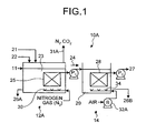
- Fig. 1 is a conceptual diagram of an apparatus for treating a radioactive nitrate waste liquid according to a first embodiment of the present invention.
- an apparatus 10A for treating a radioactive nitrate waste liquid is an apparatus for treating a radioactive nitrate waste liquid including a denitrification tank 12A which accommodates active sludge that adsorbs or takes in a radioactive substance in a nitrate waste liquid 11 containing nitrate and the radioactive substance and in which an anaerobic microorganism that reduces the nitrate to nitrogen gas grows, and a reaeration tank 14 in which a denitrification-treated liquid 24 treated in the denitrification tank 12A is aerated and mixed with the active sludge.
- the denitrification tank 12A further includes a pH adjusting unit (not shown) that supplies a pH adjuster 21 used for adjusting pH of the nitrate waste liquid 11, a carbon-source supplying unit (not shown) that supplies a carbon source 22 to the denitrification tank 12A, a first solid-liquid separating film 25 that is a first solid-liquid separating unit that separates a denitrified liquid 23 treated with the active sludge into a solid content containing sludge (redundant sludge 26A) and a treated liquid, and a gas supplying unit 30 that is arranged on a lower side of the first solid-liquid separating film 25 and supplies gas not containing oxygen (for example, one or both of nitrogen gas (N 2 ) and carbon dioxide gas (CO 2 ) into the denitrification tank 12A.
- a pH adjusting unit that supplies a pH adjuster 21 used for adjusting pH of the nitrate waste liquid 11
- a carbon-source supplying unit (not shown) that supplies
- the reaeration tank 14 includes a second solid-liquid separating film 28 or a second solid-liquid separating unit that reaerates the denitrification-treated liquid 24 treated with the active sludge to further separate a reaerated liquid 29 into redundant sludge 26B and a reaeration-treated liquid 27, and an air supplying unit 34 that is arranged on a lower side of the second solid-liquid separating film 28 and uses a blower 32A to supply air into the reaeration tank 14.
- the gas supplying unit 30 and the air supplying unit 34 are arranged, respectively.
- a liquid mixed with the active sludge passes through surfaces of the separating films, and at this time, the liquid only permeates the films, and a solid-liquid separation is performed in this way.
- the active sludge that is left after the separation adheres to the film surface; however, the film surface is always cleansed with a flow of the supplied gas. As a result, the active sludge that adheres to the film surface is cleansed and reduced. This makes it possible to perform a solid-liquid separation by using the film surface that is always clean.
- reference character P 1 denotes a denitrification-treated-liquid supplying pump that supplies the denitrification-treated liquid 24 to the reaeration tank 14 and reference character P 2 denotes a reaeration-treated-liquid supplying pump that sends the reaeration-treated liquid 27.
- the first solid-liquid separating film 25 and the second solid-liquid separating film 28 are respectively arranged in the denitrification tank 12A and the reaeration tank 14. Accordingly, the minute sludge can be completely separated into the denitrified liquid 23 or the reaerated liquid 29. This can prevent the sludge from flowing out.
- examples of types of the first solid-liquid separating film 25 and the second solid-liquid separating film 28 include well-known solid-liquid separating films such as a flat film and a hollow fiber film.
- the first solid-liquid separating film 25 When the first solid-liquid separating film 25 is installed within the denitrification tank 12A, it is possible to prevent denitrifying bacteria from flowing out, and there is no contamination of any other bacteria. Thus, only a large amount of denitrifying bacteria multiplied within the denitrification tank 12A exist in the tank. As a result, a sufficient amount of sludge can be secured, and the sludge concentration within the denitrification tank 12A can be maintained at a high level.
- a particulate radioactive substance contained in the nitrate waste liquid 11 can be also separated from the reaeration liquid 29.
- the pH of the denitrified liquid 23 in the denitrification tank 12A is preferably adjusted between 7.0 and 10.0. It is preferable that the pH is from 8.0 to 9.5, and more preferably the pH is from 8.0 to 9.0. This is because when the pH of the denitrified liquid 23 exceeds 10.0, the microorganism is perished. Moreover, when the pH is less than 7.0, a reaction rate for a treatment for reducing the nitrogen gas in the microorganism is decreased.
- the gas supplying unit 30 is arranged on a lower side (bottom surface side of the tank) of the first solid-liquid separating film 25 of the denitrification tank 12A so as to supply gas not containing oxygen (for example, nitrogen gas) to the denitrified liquid 23 of the denitrification tank 12A.
- oxygen for example, nitrogen gas
- the denitrified liquid 23 in the denitrification tank 12A can be forcedly stirred and the treatment for reducing the nitrogen gas by the microorganisms can be accelerated. Moreover, when nitrogen gas is supplied via the gas supplying unit 30 from below the first solid-liquid separating film 25, the active sludge that adheres to the first solid-liquid separating film 25 can be reduced. As a result, due to a gas cleansing effect, clogging of the film can be prevented.
- nitrogen gas is supplied by the gas supplying unit.
- the present invention is not limited thereto, and any gas that does not contain oxygen, such as carbon dioxide gas (CO 2 gas) and an inactive gas, can be used.
- nitrogen gas (N 2 ) and carbon dioxide gas (CO 2 gas) generated in the denitrification tank 12A are released to outside via a gas discharge line 31A.
- the sludge used in sewage sludge or an industrial waste treatment is put in as seed sludge and active sludge multiplied until the active sludge concentration reaches, for example, about 5,000 to 20,000 mg/L, can be used.
- the active sludge can be held by a granular carrier or a fibrous carrier, in the exemplary embodiments of the present invention, various types of such carriers are not used, and floating active sludge is preferably used.
- examples of the carbon source 22 include organic acid such as acetic acid.
- examples of the pH adjuster 21 include sulfuric acid and hydrochloric acid.
- the apparatus 10A for treating a radioactive nitrate waste liquid As the microorganism contained in the active sludge in the denitrification tank 12, a well-known anaerobic microorganism that exhibits a denitrification performance can be used. Although not particularly limited thereto, in the reaeration tank 14, a well-known aerobic microorganism for a reaeration can be used.
- the solid-liquid separating film is used as a solid-liquid separating unit; however, the present invention is not limited thereto, and any unit that can separate the sludge and the liquid can be used.
- the first solid-liquid separating film 25 and the second solid-liquid separating film 28 are respectively arranged in the denitrification tank 12A and the reaeration tank 14. Accordingly, the minute sludge can be completely separated into the denitrification-treated liquid 24 and the reaeration-treated liquid 27. Thus, the radioactive substance and the sludge can be prevented from flowing out. Moreover, the concentration of suspended solid (SS) in the reaeration-treated liquid 27 that is discharged from the reaeration tank 14 and is separately treated can be improved.
- SS suspended solid
- the sludge concentration within the denitrification tank 12A can be maintained at a high level. Therefore, a high-level denitrification performance of the denitrification tank 12A can be maintained and the apparatus can be made compact.
- a denitrification test was conducted on a nitrate waste liquid having an undiluted nitrate nitrogen concentration of 6700 to 9200 mg/L (salt concentration: 4.0 to 5.5%) by using methanol and acetic acid as a carbon source with a test temperature set to 20 to 25°C (room temperature).
- the denitrification performance reached 2kg-N/m 3 /d, whereas when the first solid-liquid separating film was arranged in the denitrification tank, the denitrification performance was improved to 7kg-N/m 3 /d.
- An apparatus 10B for treating a radioactive nitrate waste liquid according to the present embodiment is configured substantially identical to the apparatus 10A for treating a radioactive nitrate waste liquid according to the first embodiment shown in Fig. 1 , and thus like reference letters or numerals are denoted to like constituent elements of the apparatus for treating a radioactive nitrate waste liquid according to the first embodiment shown in Fig. 1 , and redundant explanations thereof will be omitted.
- Fig. 2 is a schematic diagram of a configuration of the apparatus for treating a radioactive nitrate waste liquid according to the second embodiment of the present invention. As shown in Fig.
- a gas circulating line 31B that circulates within a denitrification tank 12B nitrogen gas (N 2 ) and carbon dioxide gas (CO 2 gas) produced by a reaction between the anaerobic microorganism and the nitrate present in the denitrified liquid 23 in the denitrification tank 12B is arranged and branched off from a part of the gas discharge line 31A.
- the nitrogen gas (N 2 ) and the carbon dioxide gas (CO 2 ) generated in the denitrification tank 12B are fed to the gas supplying unit 30 by a blower 32B interposed through the gas circulating line 31B and then introduced into the denitrification tank 12B.
- the nitrogen gas (N 2 ) and the carbon dioxide gas (CO 2 ) generated as a result of the microorganism reaction within the denitrification tank 12B are re-circulated and re-used within the denitrification tank 12B.
- the nitrogen-gas supplying unit as shown in Fig. 1
- a pressure valve 33 that discharges a gas to outside from a portion of the gas discharge line 31A that discharges nitrogen gas (N 2 ) and carbon dioxide gas (CO 2 ) generated in the denitrification tank 12B. Thereby, redundant nitrogen gas (N 2 ) and carbon dioxide gas (CO 2 ) can be released by opening the pressure valve 33.
- the nitrogen gas (N 2 ) and the carbon dioxide gas (CO 2 ) generated in the denitrification tank 12B are used, the gas consumes itself efficiently. As a result, the gas supply apparatus and gas purchasing costs can be reduced.
- the apparatus for treating a radioactive nitrate waste liquid according to the present embodiment is configured substantially identical to the apparatus for treating a radioactive nitrate waste liquid according to the first embodiment shown in Fig. 1 , and thus like reference numerals are denoted to like constituent elements of the apparatus for treating a radioactive nitrate waste liquid according to the first embodiment shown in Fig. 1 , and redundant explanations thereof will be omitted.
- Fig. 3 is a schematic diagram of a configuration of the apparatus for treating a radioactive nitrate waste liquid according to the third embodiment of the present invention.
- a denitrification tank 12C As shown in Fig. 3 , in an apparatus 10C for treating a radioactive nitrate waste liquid according to the present embodiment, as the gas introduced into a denitrification tank 12C, carbon dioxide gas (CO 2 ) as well as nitrogen gas (N 2 ) is introduced as a pH treating agent.
- CO 2 carbon dioxide gas
- N 2 nitrogen gas
- the apparatus 10C for treating a radioactive nitrate waste liquid includes a gas-introducing line 35 that introduces carbon dioxide gas (CO 2 ) and nitrogen gas (N 2 ), a pH sensor 36 that measures pH in the denitrified liquid 23, and a carbon-dioxide-gas supply-amount adjusting valve 37 that adjusts the amount of carbon dioxide gas (CO 2 ) supplied as the pH treating agent to the denitrification tank 12C.
- a gas-introducing line 35 that introduces carbon dioxide gas (CO 2 ) and nitrogen gas (N 2 )
- a pH sensor 36 that measures pH in the denitrified liquid 23
- a carbon-dioxide-gas supply-amount adjusting valve 37 that adjusts the amount of carbon dioxide gas (CO 2 ) supplied as the pH treating agent to the denitrification tank 12C.
- the carbon-dioxide-gas supply-amount adjusting valve 37 is opened to lower the pH of the denitrified liquid 23.
- the carbon-dioxide-gas supply-amount adjusting valve 37 is closed to raise the pH in the denitrification tank 12C. This eliminates necessity of adding a pH adjuster such as sulfuric acid and hydrochloric acid.
- the apparatus 10C for treating a radioactive nitrate waste liquid of the present embodiment when the pH in the denitrification tank 12C is measured by the pH sensor 36 to control the pH in the denitrification tank 12C, the microorganism in the denitrification tank 12C becomes capable of an efficient denitrification reaction, and thus it is possible to prevent inhibition of the denitrification reaction by the microorganism in the denitrification tank 12C.
- carbon dioxide gas can be used as the pH adjuster 21.
- the carbon dioxide gas (CO 2 ) that is separately supplied is used for cleansing the first solid-liquid separating film 25 and used as the pH adjuster 21, and thus it is possible to prevent inhibition of the denitrification reaction.
- CO 2 carbon dioxide gas
- the apparatus for treating a radioactive nitrate waste liquid according to the present embodiment is configured substantially identical to the apparatus for treating a radioactive nitrate waste liquid according to the first embodiment shown in Fig. 1 , and thus like reference letters or numerals are denoted to like constituent elements of the apparatus for treating a radioactive nitrate waste liquid according to the first embodiment shown in Fig. 1 , and redundant explanations thereof will be omitted.
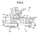
- Fig. 4 is a schematic diagram of a configuration of the apparatus for treating a radioactive nitrate waste liquid according to the fourth embodiment of the present invention.
- an apparatus 10D for treating a radioactive nitrate waste liquid according to the present embodiment includes the gas circulating line 31B (that introduces the carbon dioxide gas (CO 2 )) only of the apparatus 10B for treating a radioactive nitrate waste liquid according to the second embodiment shown in Fig. 2 , the pH sensor 36 that measures the pH of the denitrified liquid 23 in the denitrification tank 12C of the apparatus 10C for treating a radioactive nitrate waste liquid according to the third embodiment shown in Fig. 3 , and the carbon-dioxide-gas supply-amount adjusting valve 37 that adjusts the amount of carbon dioxide gas (CO 2 ) supplied to a denitrification tank 12D.
- the gas circulating line 31B that introduces the carbon dioxide gas (CO 2 )
- the pH sensor 36 that measures the pH of the denitrified liquid 23 in the denitrification tank 12C of the apparatus 10C for treating a radioactive nitrate waste liquid according to the third embodiment shown in Fig. 3
- the carbon dioxide gas (CO 2 ) that is separately supplied is used for cleansing the first solid-liquid separating film 25 and used as the pH adjuster 21, and thus it is possible to prevent inhibition of the denitrification reaction.
- CO 2 carbon dioxide gas
- the apparatus for treating a radioactive nitrate waste liquid according to the present embodiment is configured substantially identical to the apparatus for treating a radioactive nitrate waste liquid according to the first embodiment shown in Fig. 1 , and thus like reference letters or numerals are denoted to like constituent elements of the apparatus for treating a radioactive nitrate waste liquid according to the first embodiment shown in Fig. 1 , and redundant explanations thereof will be omitted.
- Fig. 5 is a schematic diagram of a configuration of an apparatus 10E for treating a radioactive nitrate waste liquid according to the fifth embodiment of the present invention.
- the apparatus 10E for treating a radioactive nitrate waste liquid according to the present embodiment uses acetic acid as the carbon source 22, and includes the pH sensor 36 that measures the pH of the nitrate waste liquid 11 in the denitrification tank 12A of the apparatus 10A for treating a radioactive nitrate waste liquid according to the first embodiment shown in Fig. 1 and a carbon-source supply-amount adjusting valve 39 that adjusts the amount of the carbon source 22 supplied to a denitrification tank 12E in an acetic-acid supplying line.
- the acetic acid used as the carbon source functions also as the pH adjuster, and thus it is possible to reduce the amount of or eliminate necessity of the pH adjuster such as sulfuric acid and hydrochloric acid.
- the carbon-source supply-amount adjusting valve 39 When the pH in the denitrification tank 12E measured by the pH sensor 36 is equal to or more than 9.0, the carbon-source supply-amount adjusting valve 39 is opened to lower the pH in the denitrification tank 12E, and when the pH in the denitrification tank 12E measured by the pH sensor 36 is equal to or less than 8.0, the carbon-source supply-amount adjusting valve 39 is closed to raise the pH in the denitrification tank 12E. In this manner, it is possible to prevent a decrease in pH caused due to excessive addition of acetic acid supplied as the carbon source and a decrease in performance inherent in nitrogen caused along therewith.
- the microorganism in the denitrification tank 12E can perform a denitrification reaction. Accordingly, it is possible to prevent inhibition of the denitrification reaction by the microorganism in the denitrification tank 12E.
- the acetic acid as the carbon source 22 is never added excessively, and thus it is possible to reduce the amount of acetic acid to be used. That is, in the conventional technique, when such an adjustment is not performed, the redundant acetic acid is dissolved in the reaeration tank 14 and a part thereof is left as the redundant sludge 26B. On the other hand, according to the apparatus 10E for treating a radioactive nitrate waste liquid of the present embodiment, the amount of acetic acid flown out to the reaeration tank 14 is reduced, and thus it is possible to reduce the amount of redundant sludge to be generated in the reaeration tank 14.
- the apparatus for treating a radioactive nitrate waste liquid according to the present embodiment is configured substantially identical to the apparatus for treating a radioactive nitrate waste liquid according to the first embodiment shown in Fig. 1 , and thus like reference letters or numerals are denoted to like constituent elements of the apparatus for treating a radioactive nitrate waste liquid according to the first embodiment shown in Fig. 1 , and redundant explanations thereof will be omitted.
- Fig. 6 is a schematic diagram of a configuration of the apparatus for treating a radioactive nitrate waste liquid according to the sixth embodiment of the present invention.
- an apparatus 10F for treating a radioactive nitrate waste liquid instead of nitrogen gas (N 2 ), air is supplied to the denitrification tank 12E. Furthermore, the apparatus 10E includes a gas circulating line that circulates the nitrogen gas and the carbon dioxide gas produced in the denitrification tank 12F into the denitrification tank 12F.
- nitrogen gas N 2
- the apparatus 10E includes a gas circulating line that circulates the nitrogen gas and the carbon dioxide gas produced in the denitrification tank 12F into the denitrification tank 12F.
- the apparatus 10F for treating a radioactive nitrate waste liquid according to the present embodiment includes an air-supplying line 41 that supplies air instead of nitrogen gas to the denitrification tank of the apparatus 10A for treating a radioactive nitrate waste liquid according to the first embodiment shown in Fig. 1 , and the gas circulating line 31B that circulates the nitrogen gas (N 2 ) and the carbon dioxide gas (CO 2 ) produced in the denitrification tank of the apparatus 10B for treating a radioactive nitrate waste liquid according to the second embodiment shown in Fig. 2 into the denitrification tank 12F.
- an air-supplying line 41 that supplies air instead of nitrogen gas to the denitrification tank of the apparatus 10A for treating a radioactive nitrate waste liquid according to the first embodiment shown in Fig. 1
- the gas circulating line 31B that circulates the nitrogen gas (N 2 ) and the carbon dioxide gas (CO 2 ) produced in the denitrification tank of the apparatus 10B for treating a radioactive nitrate waste liquid according to
- an air-supply-amount adjusting valve 42 is arranged in the air-supplying line 41, and the air-supply-amount adjusting valve 42 is repeatedly opened and closed at regular intervals.
- the valve 42 can be opened and closed, for example, for about two to five minutes a week, to supply air intermittently to the denitrification tank 12F.
- acetic acid is used as the organic acid; however, the present invention is not limited thereto.
- organic acid such as formic acid and propionic acid
- sweetener such as glucose, fructose, maltose, sucrose, and galactose can be also used.
- a reductive atmosphere in the denitrification tank 12F is mitigated, and thus generation of hydrogen sulfide (H 2 S) can be prevented and it is possible to suppress the corrosion of piping of a reaction container, for example.
- the apparatus for treating a radioactive nitrate waste liquid according to the present embodiment is configured substantially identical to the apparatus for treating a radioactive nitrate waste liquid according to the first embodiment shown in Fig. 1 , and thus like reference letters or numerals are denoted to like constituent elements of the apparatus for treating a radioactive nitrate waste liquid according to the first embodiment shown in Fig. 1 , and redundant explanations thereof will be omitted.
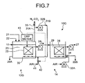
- Fig. 7 is a schematic diagram of a configuration of the apparatus for treating a radioactive nitrate waste liquid according to the seventh embodiment of the present invention.
- an apparatus 10G for treating a radioactive nitrate waste liquid instead of nitrogen gas, air is supplied to the denitrification tank, and includes the gas circulating line 31B that circulates nitrogen gas (N 2 ) and carbon dioxide gas (CO 2 ) produced in a denitrification tank 12G into the denitrification tank 12G.
- nitrogen gas N 2
- CO 2 carbon dioxide gas
- the apparatus 10G for treating a radioactive nitrate waste liquid according to the present embodiment is configured by adding, in the denitrification tank 12G, an oxidation-reduction potential meter (ORP meter) 43 that measures the oxidation reduction potential (ORP) of the denitrified liquid 23, to the apparatus 10F for treating a radioactive nitrate waste liquid according to the sixth embodiment shown in Fig. 6 .
- ORP meter an oxidation-reduction potential meter
- the air-supply-amount adjusting valve 42 is controlled so that the amount of air supplied to the denitrification tank 12G is adjusted.
- the air-supply-amount adjusting valve 42 is opened.
- the air-supply-amount adjusting valve 42 is closed.
- the oxidation-reduction potential of the denitrified liquid 23 in the denitrification tank 12G is measured by the oxidation-reduction potential meter 43, the oxidation-reduction potential of the denitrified liquid 23 in the denitrification tank 12G can be controlled within a constant range, and thus, even when the oxidation-reduction potential rises abnormally, a decrease in denitrification performance can be prevented.
- FIG. 8 is a schematic diagram of a configuration of the apparatus for treating a radioactive nitrate waste liquid according to the eighth embodiment of the present invention. As shown in Fig.
- an adjusting tank 51 that supplies a nitrate waste liquid (undiluted: salt concentration of 30 to 40%) 50 is arranged at an upstream of the denitrification tank 12A of the apparatus 10A for treating a radioactive nitrate waste liquid according to the first embodiment shown in Fig. 1 .
- the adjusting tank 51 includes an electrical conductivity meter (EC meter) 52 that measures a level of electric conductivity, an industrial-water introducing line 53, and an industrial-water supply-amount adjusting valve 54 which is arranged in the industrial-water introducing line 53 and which adjusts a flow rate of water to be diluted based on a measurement value of the electrical conductivity meter (EC meter) 52.
- EC meter electrical conductivity meter
- the industrial-water supply-amount adjusting valve 54 arranged in the industrial-water introducing line 53 is controlled based on the EC value measured by the electrical conductivity meter (EC meter) 52 arranged in the adjusting tank 51 to adjust the flow rate of water supplied to the adjusting tank 51.
- EC meter electrical conductivity meter
- the industrial-water supply-amount adjusting valve 54 is opened, and when the EC value measured by the electrical conductivity meter (EC meter) 52 is low, the industrial-water supply-amount adjusting valve 54 is closed.
- a control range of an EC value measured by the electrical conductivity meter (EC meter) 52 at this time is preferably from 50 to 70 mS/cm, and more preferably from 53 to 68 mS/cm.
- a nitrate-waste-liquid supplying pump P 3 is arranged in a nitrate-waste-liquid supplying line 55 that feeds the nitrate waste liquid 50 (undiluted liquid) to the adjusting tank 51. Based on the EC value measured by the electrical conductivity meter (EC meter) 52, the nitrate-waste-liquid supplying pump P 3 is controlled, and a supply amount of the nitrate waste liquid 50 to be fed to the adjusting tank 51 is thus adjusted.
- the nitrate-waste-liquid supplying pump P 3 is stopped to halt supplying of the undiluted nitrate waste liquid (undiluted liquid) 50 to the adjusting tank 51, and when the EC value measured by the electrical conductivity meter (EC meter) 52 is low, the nitrate-waste-liquid supplying pump P 3 is operated and the nitrate waste liquid 50 (undiluted liquid) is supplied to the adjusting tank 51.
- the concentration of a high-concentration nitrate waste liquid from treatment facilities is not always constant, and thus, even when the concentration of the nitrate waste liquid (undiluted liquid) 50 is not constant, it is possible to prevent transferring variation of the salt concentration in the nitrate waste liquid (undiluted liquid) 50 to the denitrification tank 12A. This makes it possible to prevent a significant decrease in denitrification performance caused when the salt concentration is greatly varied.
- the nitrate waste liquid (diluted liquid) 11 with a constant salt concentration can be supplied to the denitrification tank 12A via the nitrate-waste-liquid supplying pump P 4 , and thus the denitrification performance can be stabilized.
- An apparatus 10I for treating a radioactive nitrate waste liquid according to the present embodiment is configured substantially identical to the apparatus 10A for treating a radioactive nitrate waste liquid according to the first embodiment shown in Fig. 1 , and thus like reference letters or numerals are denoted to like constituent elements of the apparatus for treating a radioactive nitrate waste liquid according to the first embodiment shown in Fig. 1 , and redundant explanations thereof will be omitted.
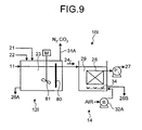
- Fig. 9 is a schematic diagram of a configuration of the apparatus for treating a radioactive nitrate waste liquid according to the ninth embodiment of the present invention. As shown in Fig.
- a denitrification tank 12I includes, instead of the first solid-liquid separating film 25, a weir 80 that prevents flowing-out sludge from leaking out.
- a stirring unit 81 that stirs the content inside of the denitrification tank 12I is also provided.
- the sludge concentration can be increased, and thus the range over which the nitrate concentration can be applied is widened.
- a biological treatment system using an apparatus for treating a radioactive nitrate waste liquid according to a tenth embodiment of the present invention is explained with reference to Fig. 10 .
- any one of the apparatuses for treating a radioactive nitrate waste liquid according to the first to ninth embodiments shown in Figs. 1 to 9 can be used, and thus explanations thereof will be omitted.
- a biological treatment system 60 includes a diluter 62 that dilutes the nitrate waste liquid (undiluted liquid) 50 with industrial water 61, a biological treatment device (any one of the apparatuses for treating a radioactive nitrate waste liquid according to the first to ninth embodiments) 63 in which nitrate ions in the diluted nitrate waste liquid 11 are microbially treated for reduction with nitrogen and reaeration, a sludge dewatering device 67 that separates sludge 65 and a treated liquid 70 from the biologically treated liquid treated in the biological treatment device 63 and dewaters the separated sludge 65, and an incinerator 69 that incinerates dewatered sludge 68.
- the diluter 62 operates in the adjusting tank 51 that dilutes an undiluted liquid as shown in Fig. 8 corresponding to the eighth embodiment described above.
- the biological treatment device 63 is an apparatus for treating a radioactive nitrate waste liquid including one of the denitrification tanks 12A to 12I and the reaeration tank 14.
- the sludge dewatering device 67 dewaters the redundant sludge discharged from the denitrification tank and the reaeration tank of the biological treatment device 63.
- the incinerator 69 incinerates the dewatered sludge 68 or secondary waste discharged from the sludge dewatering device 67 into incinerated ashes 71.
- the salt concentration in the water that adheres to the sludge is high, and thus an amount of secondary waste (incinerated ashes) occasionally increases.
- the industrial water 61 is added to flush the adhered liquid having a high salt concentration, and flushed cleansing water 72 is used as diluting water in the diluter 62 that dilutes the nitrate waste liquid 11.
- the amount of the secondary waste (incinerated ashes) can be decreased to about 1/2.
- a waste liquid with a high nitrate concentration discharged from nuclear facilities such as a reprocessing plant can be microbially treated efficiently, and minute sludge can be prevented from flowing out with a treated liquid.
Landscapes
- Life Sciences & Earth Sciences (AREA)
- Engineering & Computer Science (AREA)
- Microbiology (AREA)
- Biodiversity & Conservation Biology (AREA)
- Organic Chemistry (AREA)
- Chemical & Material Sciences (AREA)
- Water Supply & Treatment (AREA)
- Environmental & Geological Engineering (AREA)
- Hydrology & Water Resources (AREA)
- High Energy & Nuclear Physics (AREA)
- General Engineering & Computer Science (AREA)
- Physics & Mathematics (AREA)
- Health & Medical Sciences (AREA)
- Molecular Biology (AREA)
- General Health & Medical Sciences (AREA)
- Biomedical Technology (AREA)
- Purification Treatments By Anaerobic Or Anaerobic And Aerobic Bacteria Or Animals (AREA)
Claims (5)
- Vorrichtung (10A; 10B; 10C; 10D; 10E; 10F; 10G; 10H; 10I) zum Behandeln einer radioaktiven Nitratabfallflüssigkeit, die Nitrat und radioaktive Substanzen enthält, umfassend:einen Denitrifikationstank (12A; 12B; 12C; 12D; 12E; 12F; 12G; 121) zum Aufnehmen von aktiviertem Schlamm, wobei der aktivierte Schlamm die radioaktive Substanz absorbiert oder adsorbiert und einen anaeroben Mikroorganismus zum Reduzieren des Nitrats in gasförmigen Stickstoff kultiviert, undeinen Wiederbelüftungstank (14) zum Belüften und Mischen einer durch Denitrifikation behandelten Flüssigkeit (24), die im Denitrifikationstank (12A; 12B; 12C; 12D; 12E; 12F; 12G; 121) behandelt wurde, mit aktiviertem Schlamm zum Kultivieren eines aeroben Mikroorganismus, wobeider Denitrifikationstank (12A; 12B; 12C; 12D; 12E; 12F; 12G; 121) umfasst:eine pH-Werteinstelleinheit zum Bereitstellen eines pH-Werteinstellers (21), um so den pH-Wert der radioaktiven Nitratabfallflüssigkeit einzustellen,eine Kohlenstoffquellenliefereinheit zur Zufuhr einer Kohlenstoffquelle (22) zum Denitrifikationstank (12A; 12B; 12C; 12D; 12E; 12F; 12G; 121),eine erste Fest-Flüssig-Trenneinheit (25) zum Trennen einer denitrifizierten Flüssigkeit (23), die mit dem aktivierten Schlamm behandelt wurde, in einen schlammhaltigen festen Anteil und die durch Denitrifikation behandelte Flüssigkeit (24),
undeine Gaszufuhreinheit (30), die auf einer unteren Seite der ersten Fest-Flüssig-Trenneinheit (25) angeordnet ist, zum Zuführen von Gas, das keinen Sauerstoff enthält, zum Denitrifikationstank (12A; 12B; 12C; 12D; 12E; 12F; 12G; 121), undder Wiederbelüftungstank (14) umfasst:eine zweite Fest-Flüssig-Trenneinheit (28) zum Trennen der durch Denitrifikation behandelten Flüssigkeit (24) in einen schlammhaltigen festen Anteil und eine behandelte Flüssigkeit, undeine Luftzufuhreinheit (34), die auf einer unteren Seite der zweiten Fest-Flüssig-Trenneinheit (28) angeordnet ist und zur Zufuhr von Luft in den Wiederbelüftungstank (14) dient,wobei die erste Fest-Flüssig-Trenneinheit (25) und die zweite Fest-Flüssig-Trenneinheit (28) Fest-Flüssig-Trennfilme sind und wobei der Denitrifikationstank (12A; 12B; 12C; 12D; 12E; 12F; 12G; 121) ferner eine Gaszirkulationsleitung (31 B) zum Umwälzen von gasförmigem Stickstoff und gasförmigem Kohlendioxid umfasst, das durch eine Reaktion zwischen dem anaeroben Mikroorganismus und dem Nitrat in der denitrifizierten Flüssigkeit (23) erzeugt wird, in den Denitrifikationstank (12A; 12B; 12C; 12D; 12E; 12F; 12G; 121) umfasst,ein Oxidations-Reduktions-Potentialmesser (43) zum Messen eines Oxidations-Reduktions-Potentials der denitrifizierten Flüssigkeit, undein Luftzufuhrmengen-Einstellventil (42) zur zeitweiligen Zufuhr von Luft zur Gaszirkulationsleitung (31 B), das auf dem gemessenen Oxidations-Reduktions-Potential beruht, um so das Oxidations-Reduktions-Potential der denitrifizierten Flüssigkeit innerhalb eines konstanten Bereichs zu halten. - Vorrichtung (10A; 10B; 10C; 10D; 10E; 10F; 10G; 10H; 10I)nach Anspruch 1, die ferner umfasst:einen pH-Sensor (36) zum Messen des pH-Wertes der denitrifizierten Flüssigkeit (23), undein Kohlendioxidgaszufuhr-Mengeneinstellventil (37) zum Einstellen einer Menge von Kohlendioxidgas, die dem Denitrifikationstank (12A; 12B; 12C; 12D; 12E; 12F; 12G; 121) zugeführt wird.
- Vorrichtung (10A; 10B; 10C; 10D; 10E; 10F; 10G; 10H; 10I) nach Anspruch 1, die ferner umfasst:einen pH-Sensor (36) zum Messen des pH-Wertes der denitrifizierten Flüssigkeit (23), undein Kohlenstoffzufuhr-Mengeneinstellventil (39) zum Einstellen einer Menge der Kohlenstoffquelle (22), die dem Denitrifikationstank (12A; 12B; 12C; 12D; 12E; 12F; 12G; 121) zugeführt wird.
- Vorrichtung (10A; 10B; 10C; 10D; 10E; 10F; 10G; 10H; 10I) nach einem der Ansprüche 1 bis 2, die ferner einen Einstelltank (51) umfasst, der stromaufwärts vom Denitrifikationstank (12A; 12B; 12C; 12D; 12E; 12F; 12G; 121) gelegen ist, wobei
der Einstelltank (51) umfasst:ein elektrisches Leitfähigkeitsmessgerät (52) zum Messen eines Grades der elektrischen Leitfähigkeit,eine Industriewassereinleitungsleitung (53), undein Industriewasser-Zufuhrmengen-Einstellventil (54), das in die Industriewassereinleitungsleitung (53) eingeschaltet ist zum Einstellen einer Wassermenge, die auf der Basis eines Messwertes des elektrischen Leitfähigkeitsmessgerätes (52) zugeführt wird. - Verfahren zum Behandeln einer radioaktiven Nitratabfallflüssigkeit, die Nitrat und radioaktive Substanzen enthält, wobei das Verfahren gekennzeichnet ist durch:Aufnehmen von Aktivschlamm in den Denitrifikationstank (12A; 12B; 12C; 12D;
12D; 12F; 12G; 121), wobei der Aktivschlamm die radioaktive Substanz absorbiert oder adsorbiert und einen anaeroben Mikroorganismus zum Reduzieren des Nitrats zu gasförmigem Stickstoff kultiviert, um so eine durch Denitrifikation behandelte Flüssigkeit (24) zu erzeugen, undBelüften und Mischen der durch Denitrifikation behandelten Flüssigkeit (24) mit Aktivschlamm zum Kultivieren eines anaeroben Mikroorganismus in einem Wiederbelüftungstank (14), wobeidas Aufnehmen des Aktivschlamms in den Denitrifikationstank (12A; 12B; 12C;
12D; 12D; 12F; 12G; 121) umfasst:Bereitstellen eines pH-Werteinstellers (21) für den Denitrifikationstank (12A;
12B; 12C; 12D; 12D; 12F; 12G; 121), um so den pH-Wert der Nitratabfallflüssigkeit einzustellen,Zuführen einer Kohlenstoffquelle (22) zum Denitrifikationstank (12A; 12B; 12C;
12D; 12D; 12F; 12G; 121),Trennen einer denitrifizierten Flüssigkeit (24) mit einer ersten Fest-Flüssig-Trenneinheit (25),Zuführen von Gas, das frei von Sauerstoff ist, zum Denitrifikationstank (12A;
12B; 12C; 12D; 12D; 12F; 12G; 121) von einer unteren Seite der ersten Fest-Flüssig-Trenneinheit (25), und wobeidas Belüften und Mischen der durch Denitrifikation behandelten Flüssigkeit (24) im Wiederbelüftungstank (14) umfasst:Trennen der durch Denitrifikation behandelten Flüssigkeit (24) in einen schlammhaltigen festen Anteil und eine behandelte Flüssigkeit mit einer zweiten Fest-Flüssig-Trenneinheit (28), undZuführen von Luft zum Wiederbelüftungstank (14) von einer unteren Seite der zweiten Fest-Flüssig-Trenneinheit (28), wobei die erste Fest-Flüssig-Trenneinheit (25) und die zweite Fest-Flüssig-Trenneinheit (28) Fest-Flüssig-Trennfilme sind und wobei der aufnehmende Aktivschlamm im Denitrifikationstank (12A; 12B; 12C; 12D; 12D; 12F; 12G; 121) ferner umfasst:Umwälzen von Stickstoffgas und Kohlendioxidgas, die durch eine Reaktion zwischen dem anaeroben Mikroorganismus und dem Nitrat in der denitrifizierten Flüssigkeit (23) erzeugt wurden, in den Denitrifikationstank über eine Gaszirkulationsleitung (31 B),Messen eines Oxidations-Reduktions-Potentials der denitrifizierten Flüssigkeit (23), undzeitweilige Zufuhr von Luft zur Gaszirkulationsleitung (31 B) auf der Basis des gemessenen Oxidations-Reduktions-Potentials, um so das Oxidations-Reduktions-Potential der denitrifizierten Flüssigkeit innerhalb eines konstanten Bereichs zu halten.
Applications Claiming Priority (2)
| Application Number | Priority Date | Filing Date | Title |
|---|---|---|---|
| JP2008029555 | 2008-02-08 | ||
| PCT/JP2009/052096 WO2009099208A1 (ja) | 2008-02-08 | 2009-02-06 | 放射性硝酸塩廃液処理装置及び方法 |
Publications (3)
| Publication Number | Publication Date |
|---|---|
| EP2242060A1 EP2242060A1 (de) | 2010-10-20 |
| EP2242060A4 EP2242060A4 (de) | 2012-07-04 |
| EP2242060B1 true EP2242060B1 (de) | 2015-07-08 |
Family
ID=40952276
Family Applications (1)
| Application Number | Title | Priority Date | Filing Date |
|---|---|---|---|
| EP09708931.2A Active EP2242060B1 (de) | 2008-02-08 | 2009-02-06 | Verfahren und vorrichtung zur bearbeitung einer radioaktiven nitratabfallflüssigkeit |
Country Status (4)
| Country | Link |
|---|---|
| US (1) | US8409438B2 (de) |
| EP (1) | EP2242060B1 (de) |
| JP (1) | JP4774120B2 (de) |
| WO (1) | WO2009099208A1 (de) |
Families Citing this family (7)
| Publication number | Priority date | Publication date | Assignee | Title |
|---|---|---|---|---|
| JP4774065B2 (ja) * | 2008-02-08 | 2011-09-14 | 三菱重工業株式会社 | 放射性硝酸塩廃液処理装置 |
| JP5797150B2 (ja) * | 2012-04-10 | 2015-10-21 | 株式会社日立パワーソリューションズ | リン酸マグネシウムアンモニウム生成抑制システム及びメタン発酵システム |
| JP2014180629A (ja) * | 2013-03-19 | 2014-09-29 | Kubota Corp | 水処理方法および水処理システム |
| CN103864205A (zh) * | 2014-03-18 | 2014-06-18 | 强成诚 | 微曝气生物膜填料 |
| CN105906058A (zh) * | 2016-06-22 | 2016-08-31 | 广州德港水产设备科技有限公司 | 一种缺氧脱氮生物过滤器及其使用方法 |
| AU2018419491A1 (en) * | 2018-04-17 | 2019-11-21 | E.L.I (Environment Laboratory Impact) Services Pte. Ltd. | Process and system for removing radioactive ions present in a liquid |
| CN114671519B (zh) * | 2022-03-09 | 2023-06-06 | 南京大学 | 一种高进水cod浓度条件下修复厌氧反应器酸化系统的方法 |
Family Cites Families (18)
| Publication number | Priority date | Publication date | Assignee | Title |
|---|---|---|---|---|
| JP2896291B2 (ja) * | 1993-06-14 | 1999-05-31 | 株式会社エイ・ティ・アール通信システム研究所 | 画像表示装置 |
| JP2600023Y2 (ja) * | 1993-08-13 | 1999-09-27 | 大同ほくさん株式会社 | 排水処理装置 |
| JP3150506B2 (ja) | 1993-10-01 | 2001-03-26 | 三菱レイヨン株式会社 | 排水処理方法 |
| FR2730584B1 (fr) * | 1995-02-10 | 1997-04-25 | Joanes Pierre Deguitre | Procede et dispositif pour traiter des huiles et solvants contamines par des substances radioactives |
| DE19529021C1 (de) * | 1995-07-28 | 1997-02-27 | Ufz Leipzighalle Gmbh | Neue sulfatreduzierende Bakterienstämme und deren Verwendung zur Dekontamination von schwefelsauren, metallbeladenen und radioaktiv verseuchten Wässern |
| US7182871B2 (en) * | 1996-12-17 | 2007-02-27 | Global Biosciences, Inc. | Wastewater treatment with alkanes |
| US6923914B2 (en) * | 1996-12-17 | 2005-08-02 | Global Biosciences, Inc. | Remediation of metal contaminants with hydrocarbon-utilizing bacteria |
| JP3697037B2 (ja) | 1997-09-22 | 2005-09-21 | 中部電力株式会社 | 生物脱窒方法 |
| JPH11156392A (ja) * | 1997-12-01 | 1999-06-15 | Mitsubishi Heavy Ind Ltd | エタノールアミン含有排水の処理方法 |
| JP4358652B2 (ja) | 2004-02-25 | 2009-11-04 | 三菱重工業株式会社 | 排水の処理装置及び方法 |
| JP2006136853A (ja) * | 2004-11-15 | 2006-06-01 | Nitto Denko Corp | 排水処理設備およびこれを用いた排水処理システム |
| JP4782576B2 (ja) * | 2005-03-25 | 2011-09-28 | シャープ株式会社 | 排水処理装置 |
| US7326343B2 (en) * | 2005-05-03 | 2008-02-05 | University Of Western Ontario Canada | Treatment of wastewater containing phosphorous and nitrogen |
| JP2007105627A (ja) * | 2005-10-13 | 2007-04-26 | Mitsubishi Heavy Ind Ltd | 硝酸塩含有廃液の処理方法と処理装置 |
| US7314563B2 (en) * | 2005-11-14 | 2008-01-01 | Korea Institute Of Science And Technology | Membrane coupled activated sludge method and apparatus operating anoxic/anaerobic process alternately for removal of nitrogen and phosphorous |
| JP4545715B2 (ja) * | 2006-07-07 | 2010-09-15 | 株式会社神鋼環境ソリューション | 有機性排水処理装置改修方法 |
| KR100722929B1 (ko) * | 2006-07-28 | 2007-05-30 | 이인형 | 물리화학적 및 생물학적 복합공정에 기반한 에탄올아민폐수의 고도처리방법 |
| GB0818698D0 (en) * | 2008-10-10 | 2008-11-19 | Univ Cranfield | Process |
-
2009
- 2009-02-06 WO PCT/JP2009/052096 patent/WO2009099208A1/ja active Application Filing
- 2009-02-06 EP EP09708931.2A patent/EP2242060B1/de active Active
- 2009-02-06 US US12/743,319 patent/US8409438B2/en active Active
- 2009-02-06 JP JP2009552550A patent/JP4774120B2/ja active Active
Also Published As
| Publication number | Publication date |
|---|---|
| US20100258500A1 (en) | 2010-10-14 |
| JP4774120B2 (ja) | 2011-09-14 |
| WO2009099208A1 (ja) | 2009-08-13 |
| EP2242060A4 (de) | 2012-07-04 |
| US8409438B2 (en) | 2013-04-02 |
| JPWO2009099208A1 (ja) | 2011-05-26 |
| EP2242060A1 (de) | 2010-10-20 |
Similar Documents
| Publication | Publication Date | Title |
|---|---|---|
| EP2239742B1 (de) | Verfahren und vorrichtung zur bearbeitung einer nitratabfallflüssigkeit | |
| EP2242060B1 (de) | Verfahren und vorrichtung zur bearbeitung einer radioaktiven nitratabfallflüssigkeit | |
| US6387254B1 (en) | Apparatus for wastewater treatment | |
| KR101294489B1 (ko) | 유기 황 화합물 함유 배수의 처리 장치 | |
| EP2242061B1 (de) | Vorrichtung und verfahren zur bearbeitung einer radioaktiven nitratsalzabfallflüssigkeit | |
| JP4872171B2 (ja) | 生物脱窒装置 | |
| JP2009136725A (ja) | アンモニア含有廃水の処理装置 | |
| KR20140063454A (ko) | 폐수 처리 방법 및 폐수 처리 장치 | |
| KR19990040951A (ko) | 고농도 유기물 및 암모니아성 질소가 포함된 침출수의 처리장치 | |
| JP5581872B2 (ja) | アンモニア性窒素廃液の脱窒処理方法及び処理装置 | |
| JP7229190B2 (ja) | アンモニア性窒素含有排水の処理方法及び処理装置 | |
| JP2012011376A (ja) | 汚水処理方法および装置 | |
| KR20100046936A (ko) | 복합탈질시스템 | |
| JP2004255269A (ja) | 脱窒方法及び脱窒装置 | |
| JP2004275820A (ja) | 排水処理装置 | |
| KR100321679B1 (ko) | 분배유입방식을이용한폐수의정화방법 | |
| KR100898640B1 (ko) | 내생탈인이 활성화된 고도처리장치 및 그의 방법 | |
| JP2000070989A (ja) | 廃水の窒素除去方法および装置 | |
| KR100202066B1 (ko) | 단일반응조에서의 생물학적 3상 소화공정을 이용한 폐수처리방법 | |
| JP7050204B1 (ja) | 高濃度有機物含有排水の排水処理設備および排水処理方法 | |
| JP7332501B2 (ja) | アンモニア性窒素含有排水の処理方法及び処理装置 | |
| JP2004188281A (ja) | 廃水処理方法及び廃水処理装置 | |
| JP2007296436A (ja) | 高濃度有機物含有排水の排水処理方法 |
Legal Events
| Date | Code | Title | Description |
|---|---|---|---|
| PUAI | Public reference made under article 153(3) epc to a published international application that has entered the european phase |
Free format text: ORIGINAL CODE: 0009012 |
|
| 17P | Request for examination filed |
Effective date: 20100531 |
|
| AK | Designated contracting states |
Kind code of ref document: A1 Designated state(s): AT BE BG CH CY CZ DE DK EE ES FI FR GB GR HR HU IE IS IT LI LT LU LV MC MK MT NL NO PL PT RO SE SI SK TR |
|
| AX | Request for extension of the european patent |
Extension state: AL BA RS |
|
| DAX | Request for extension of the european patent (deleted) | ||
| A4 | Supplementary search report drawn up and despatched |
Effective date: 20120604 |
|
| RIC1 | Information provided on ipc code assigned before grant |
Ipc: C02F 3/28 20060101ALI20120529BHEP Ipc: C02F 3/30 20060101AFI20120529BHEP Ipc: C02F 3/12 20060101ALI20120529BHEP Ipc: G21F 9/06 20060101ALI20120529BHEP Ipc: G21F 9/18 20060101ALI20120529BHEP |
|
| 17Q | First examination report despatched |
Effective date: 20130515 |
|
| REG | Reference to a national code |
Ref country code: DE Ref legal event code: R079 Ref document number: 602009032062 Country of ref document: DE Free format text: PREVIOUS MAIN CLASS: G21F0009180000 Ipc: C02F0003120000 |
|
| RIC1 | Information provided on ipc code assigned before grant |
Ipc: C02F 3/12 20060101AFI20141222BHEP Ipc: C02F 3/34 20060101ALN20141222BHEP Ipc: C02F 3/30 20060101ALI20141222BHEP Ipc: G21F 9/06 20060101ALI20141222BHEP Ipc: C02F 1/66 20060101ALN20141222BHEP Ipc: C02F 101/00 20060101ALN20141222BHEP Ipc: C02F 3/28 20060101ALI20141222BHEP Ipc: G21F 9/18 20060101ALI20141222BHEP |
|
| GRAP | Despatch of communication of intention to grant a patent |
Free format text: ORIGINAL CODE: EPIDOSNIGR1 |
|
| INTG | Intention to grant announced |
Effective date: 20150209 |
|
| GRAS | Grant fee paid |
Free format text: ORIGINAL CODE: EPIDOSNIGR3 |
|
| GRAA | (expected) grant |
Free format text: ORIGINAL CODE: 0009210 |
|
| AK | Designated contracting states |
Kind code of ref document: B1 Designated state(s): AT BE BG CH CY CZ DE DK EE ES FI FR GB GR HR HU IE IS IT LI LT LU LV MC MK MT NL NO PL PT RO SE SI SK TR |
|
| REG | Reference to a national code |
Ref country code: GB Ref legal event code: FG4D |
|
| REG | Reference to a national code |
Ref country code: AT Ref legal event code: REF Ref document number: 735253 Country of ref document: AT Kind code of ref document: T Effective date: 20150715 Ref country code: CH Ref legal event code: EP |
|
| REG | Reference to a national code |
Ref country code: IE Ref legal event code: FG4D |
|
| REG | Reference to a national code |
Ref country code: DE Ref legal event code: R096 Ref document number: 602009032062 Country of ref document: DE |
|
| REG | Reference to a national code |
Ref country code: AT Ref legal event code: MK05 Ref document number: 735253 Country of ref document: AT Kind code of ref document: T Effective date: 20150708 |
|
| REG | Reference to a national code |
Ref country code: NL Ref legal event code: MP Effective date: 20150708 |
|
| REG | Reference to a national code |
Ref country code: LT Ref legal event code: MG4D |
|
| REG | Reference to a national code |
Ref country code: FR Ref legal event code: PLFP Year of fee payment: 8 |
|
| PG25 | Lapsed in a contracting state [announced via postgrant information from national office to epo] |
Ref country code: LT Free format text: LAPSE BECAUSE OF FAILURE TO SUBMIT A TRANSLATION OF THE DESCRIPTION OR TO PAY THE FEE WITHIN THE PRESCRIBED TIME-LIMIT Effective date: 20150708 Ref country code: FI Free format text: LAPSE BECAUSE OF FAILURE TO SUBMIT A TRANSLATION OF THE DESCRIPTION OR TO PAY THE FEE WITHIN THE PRESCRIBED TIME-LIMIT Effective date: 20150708 Ref country code: GR Free format text: LAPSE BECAUSE OF FAILURE TO SUBMIT A TRANSLATION OF THE DESCRIPTION OR TO PAY THE FEE WITHIN THE PRESCRIBED TIME-LIMIT Effective date: 20151009 Ref country code: LV Free format text: LAPSE BECAUSE OF FAILURE TO SUBMIT A TRANSLATION OF THE DESCRIPTION OR TO PAY THE FEE WITHIN THE PRESCRIBED TIME-LIMIT Effective date: 20150708 Ref country code: NO Free format text: LAPSE BECAUSE OF FAILURE TO SUBMIT A TRANSLATION OF THE DESCRIPTION OR TO PAY THE FEE WITHIN THE PRESCRIBED TIME-LIMIT Effective date: 20151008 |
|
| PG25 | Lapsed in a contracting state [announced via postgrant information from national office to epo] |
Ref country code: PT Free format text: LAPSE BECAUSE OF FAILURE TO SUBMIT A TRANSLATION OF THE DESCRIPTION OR TO PAY THE FEE WITHIN THE PRESCRIBED TIME-LIMIT Effective date: 20151109 Ref country code: SE Free format text: LAPSE BECAUSE OF FAILURE TO SUBMIT A TRANSLATION OF THE DESCRIPTION OR TO PAY THE FEE WITHIN THE PRESCRIBED TIME-LIMIT Effective date: 20150708 Ref country code: HR Free format text: LAPSE BECAUSE OF FAILURE TO SUBMIT A TRANSLATION OF THE DESCRIPTION OR TO PAY THE FEE WITHIN THE PRESCRIBED TIME-LIMIT Effective date: 20150708 Ref country code: PL Free format text: LAPSE BECAUSE OF FAILURE TO SUBMIT A TRANSLATION OF THE DESCRIPTION OR TO PAY THE FEE WITHIN THE PRESCRIBED TIME-LIMIT Effective date: 20150708 Ref country code: IS Free format text: LAPSE BECAUSE OF FAILURE TO SUBMIT A TRANSLATION OF THE DESCRIPTION OR TO PAY THE FEE WITHIN THE PRESCRIBED TIME-LIMIT Effective date: 20151108 Ref country code: AT Free format text: LAPSE BECAUSE OF FAILURE TO SUBMIT A TRANSLATION OF THE DESCRIPTION OR TO PAY THE FEE WITHIN THE PRESCRIBED TIME-LIMIT Effective date: 20150708 Ref country code: ES Free format text: LAPSE BECAUSE OF FAILURE TO SUBMIT A TRANSLATION OF THE DESCRIPTION OR TO PAY THE FEE WITHIN THE PRESCRIBED TIME-LIMIT Effective date: 20150708 |
|
| REG | Reference to a national code |
Ref country code: DE Ref legal event code: R097 Ref document number: 602009032062 Country of ref document: DE |
|
| PG25 | Lapsed in a contracting state [announced via postgrant information from national office to epo] |
Ref country code: SK Free format text: LAPSE BECAUSE OF FAILURE TO SUBMIT A TRANSLATION OF THE DESCRIPTION OR TO PAY THE FEE WITHIN THE PRESCRIBED TIME-LIMIT Effective date: 20150708 Ref country code: DK Free format text: LAPSE BECAUSE OF FAILURE TO SUBMIT A TRANSLATION OF THE DESCRIPTION OR TO PAY THE FEE WITHIN THE PRESCRIBED TIME-LIMIT Effective date: 20150708 Ref country code: CZ Free format text: LAPSE BECAUSE OF FAILURE TO SUBMIT A TRANSLATION OF THE DESCRIPTION OR TO PAY THE FEE WITHIN THE PRESCRIBED TIME-LIMIT Effective date: 20150708 Ref country code: IT Free format text: LAPSE BECAUSE OF FAILURE TO SUBMIT A TRANSLATION OF THE DESCRIPTION OR TO PAY THE FEE WITHIN THE PRESCRIBED TIME-LIMIT Effective date: 20150708 Ref country code: EE Free format text: LAPSE BECAUSE OF FAILURE TO SUBMIT A TRANSLATION OF THE DESCRIPTION OR TO PAY THE FEE WITHIN THE PRESCRIBED TIME-LIMIT Effective date: 20150708 |
|
| PLBE | No opposition filed within time limit |
Free format text: ORIGINAL CODE: 0009261 |
|
| STAA | Information on the status of an ep patent application or granted ep patent |
Free format text: STATUS: NO OPPOSITION FILED WITHIN TIME LIMIT |
|
| PG25 | Lapsed in a contracting state [announced via postgrant information from national office to epo] |
Ref country code: BE Free format text: LAPSE BECAUSE OF NON-PAYMENT OF DUE FEES Effective date: 20160229 Ref country code: RO Free format text: LAPSE BECAUSE OF FAILURE TO SUBMIT A TRANSLATION OF THE DESCRIPTION OR TO PAY THE FEE WITHIN THE PRESCRIBED TIME-LIMIT Effective date: 20150708 |
|
| 26N | No opposition filed |
Effective date: 20160411 |
|
| PG25 | Lapsed in a contracting state [announced via postgrant information from national office to epo] |
Ref country code: SI Free format text: LAPSE BECAUSE OF FAILURE TO SUBMIT A TRANSLATION OF THE DESCRIPTION OR TO PAY THE FEE WITHIN THE PRESCRIBED TIME-LIMIT Effective date: 20150708 |
|
| REG | Reference to a national code |
Ref country code: DE Ref legal event code: R119 Ref document number: 602009032062 Country of ref document: DE |
|
| PG25 | Lapsed in a contracting state [announced via postgrant information from national office to epo] |
Ref country code: LU Free format text: LAPSE BECAUSE OF FAILURE TO SUBMIT A TRANSLATION OF THE DESCRIPTION OR TO PAY THE FEE WITHIN THE PRESCRIBED TIME-LIMIT Effective date: 20160206 Ref country code: MC Free format text: LAPSE BECAUSE OF FAILURE TO SUBMIT A TRANSLATION OF THE DESCRIPTION OR TO PAY THE FEE WITHIN THE PRESCRIBED TIME-LIMIT Effective date: 20150708 |
|
| REG | Reference to a national code |
Ref country code: CH Ref legal event code: PL |
|
| PG25 | Lapsed in a contracting state [announced via postgrant information from national office to epo] |
Ref country code: CH Free format text: LAPSE BECAUSE OF NON-PAYMENT OF DUE FEES Effective date: 20160229 Ref country code: LI Free format text: LAPSE BECAUSE OF NON-PAYMENT OF DUE FEES Effective date: 20160229 |
|
| REG | Reference to a national code |
Ref country code: IE Ref legal event code: MM4A |
|
| PG25 | Lapsed in a contracting state [announced via postgrant information from national office to epo] |
Ref country code: BE Free format text: LAPSE BECAUSE OF FAILURE TO SUBMIT A TRANSLATION OF THE DESCRIPTION OR TO PAY THE FEE WITHIN THE PRESCRIBED TIME-LIMIT Effective date: 20150708 |
|
| REG | Reference to a national code |
Ref country code: FR Ref legal event code: PLFP Year of fee payment: 9 |
|
| PG25 | Lapsed in a contracting state [announced via postgrant information from national office to epo] |
Ref country code: IE Free format text: LAPSE BECAUSE OF NON-PAYMENT OF DUE FEES Effective date: 20160206 Ref country code: DE Free format text: LAPSE BECAUSE OF NON-PAYMENT OF DUE FEES Effective date: 20160901 |
|
| PG25 | Lapsed in a contracting state [announced via postgrant information from national office to epo] |
Ref country code: NL Free format text: LAPSE BECAUSE OF FAILURE TO SUBMIT A TRANSLATION OF THE DESCRIPTION OR TO PAY THE FEE WITHIN THE PRESCRIBED TIME-LIMIT Effective date: 20150708 |
|
| PG25 | Lapsed in a contracting state [announced via postgrant information from national office to epo] |
Ref country code: MT Free format text: LAPSE BECAUSE OF FAILURE TO SUBMIT A TRANSLATION OF THE DESCRIPTION OR TO PAY THE FEE WITHIN THE PRESCRIBED TIME-LIMIT Effective date: 20150708 |
|
| REG | Reference to a national code |
Ref country code: FR Ref legal event code: PLFP Year of fee payment: 10 |
|
| PG25 | Lapsed in a contracting state [announced via postgrant information from national office to epo] |
Ref country code: CY Free format text: LAPSE BECAUSE OF FAILURE TO SUBMIT A TRANSLATION OF THE DESCRIPTION OR TO PAY THE FEE WITHIN THE PRESCRIBED TIME-LIMIT Effective date: 20150708 Ref country code: HU Free format text: LAPSE BECAUSE OF FAILURE TO SUBMIT A TRANSLATION OF THE DESCRIPTION OR TO PAY THE FEE WITHIN THE PRESCRIBED TIME-LIMIT; INVALID AB INITIO Effective date: 20090206 |
|
| PG25 | Lapsed in a contracting state [announced via postgrant information from national office to epo] |
Ref country code: TR Free format text: LAPSE BECAUSE OF FAILURE TO SUBMIT A TRANSLATION OF THE DESCRIPTION OR TO PAY THE FEE WITHIN THE PRESCRIBED TIME-LIMIT Effective date: 20150708 Ref country code: MK Free format text: LAPSE BECAUSE OF FAILURE TO SUBMIT A TRANSLATION OF THE DESCRIPTION OR TO PAY THE FEE WITHIN THE PRESCRIBED TIME-LIMIT Effective date: 20150708 Ref country code: MT Free format text: LAPSE BECAUSE OF FAILURE TO SUBMIT A TRANSLATION OF THE DESCRIPTION OR TO PAY THE FEE WITHIN THE PRESCRIBED TIME-LIMIT Effective date: 20160229 |
|
| PG25 | Lapsed in a contracting state [announced via postgrant information from national office to epo] |
Ref country code: BG Free format text: LAPSE BECAUSE OF FAILURE TO SUBMIT A TRANSLATION OF THE DESCRIPTION OR TO PAY THE FEE WITHIN THE PRESCRIBED TIME-LIMIT Effective date: 20150708 |
|
| PGFP | Annual fee paid to national office [announced via postgrant information from national office to epo] |
Ref country code: FR Payment date: 20220118 Year of fee payment: 14 |
|
| P01 | Opt-out of the competence of the unified patent court (upc) registered |
Effective date: 20230522 |
|
| PGFP | Annual fee paid to national office [announced via postgrant information from national office to epo] |
Ref country code: GB Payment date: 20240108 Year of fee payment: 16 |