EP2241715B2 - Haustür mit faserverstärktem Kunststoffmaterial - Google Patents
Haustür mit faserverstärktem Kunststoffmaterial Download PDFInfo
- Publication number
- EP2241715B2 EP2241715B2 EP10159045.3A EP10159045A EP2241715B2 EP 2241715 B2 EP2241715 B2 EP 2241715B2 EP 10159045 A EP10159045 A EP 10159045A EP 2241715 B2 EP2241715 B2 EP 2241715B2
- Authority
- EP
- European Patent Office
- Prior art keywords
- profile
- door leaf
- fiber
- door
- frame
- Prior art date
- Legal status (The legal status is an assumption and is not a legal conclusion. Google has not performed a legal analysis and makes no representation as to the accuracy of the status listed.)
- Active
Links
Images


Classifications
-
- E—FIXED CONSTRUCTIONS
- E06—DOORS, WINDOWS, SHUTTERS, OR ROLLER BLINDS IN GENERAL; LADDERS
- E06B—FIXED OR MOVABLE CLOSURES FOR OPENINGS IN BUILDINGS, VEHICLES, FENCES OR LIKE ENCLOSURES IN GENERAL, e.g. DOORS, WINDOWS, BLINDS, GATES
- E06B3/00—Window sashes, door leaves, or like elements for closing wall or like openings; Layout of fixed or moving closures, e.g. windows in wall or like openings; Features of rigidly-mounted outer frames relating to the mounting of wing frames
- E06B3/70—Door leaves
- E06B3/7015—Door leaves characterised by the filling between two external panels
-
- E—FIXED CONSTRUCTIONS
- E06—DOORS, WINDOWS, SHUTTERS, OR ROLLER BLINDS IN GENERAL; LADDERS
- E06B—FIXED OR MOVABLE CLOSURES FOR OPENINGS IN BUILDINGS, VEHICLES, FENCES OR LIKE ENCLOSURES IN GENERAL, e.g. DOORS, WINDOWS, BLINDS, GATES
- E06B1/00—Border constructions of openings in walls, floors, or ceilings; Frames to be rigidly mounted in such openings
- E06B1/04—Frames for doors, windows, or the like to be fixed in openings
- E06B1/32—Frames composed of parts made of different materials
- E06B1/325—Frames composed of parts made of different materials comprising insulation between two metal section members
-
- E—FIXED CONSTRUCTIONS
- E06—DOORS, WINDOWS, SHUTTERS, OR ROLLER BLINDS IN GENERAL; LADDERS
- E06B—FIXED OR MOVABLE CLOSURES FOR OPENINGS IN BUILDINGS, VEHICLES, FENCES OR LIKE ENCLOSURES IN GENERAL, e.g. DOORS, WINDOWS, BLINDS, GATES
- E06B3/00—Window sashes, door leaves, or like elements for closing wall or like openings; Layout of fixed or moving closures, e.g. windows in wall or like openings; Features of rigidly-mounted outer frames relating to the mounting of wing frames
- E06B3/04—Wing frames not characterised by the manner of movement
- E06B3/263—Frames with special provision for insulation
- E06B3/26301—Frames with special provision for insulation with prefabricated insulating strips between two metal section members
- E06B3/26303—Frames with special provision for insulation with prefabricated insulating strips between two metal section members with thin strips, e.g. defining a hollow space between the metal section members
-
- E—FIXED CONSTRUCTIONS
- E06—DOORS, WINDOWS, SHUTTERS, OR ROLLER BLINDS IN GENERAL; LADDERS
- E06B—FIXED OR MOVABLE CLOSURES FOR OPENINGS IN BUILDINGS, VEHICLES, FENCES OR LIKE ENCLOSURES IN GENERAL, e.g. DOORS, WINDOWS, BLINDS, GATES
- E06B3/00—Window sashes, door leaves, or like elements for closing wall or like openings; Layout of fixed or moving closures, e.g. windows in wall or like openings; Features of rigidly-mounted outer frames relating to the mounting of wing frames
- E06B3/70—Door leaves
- E06B3/72—Door leaves consisting of frame and panels, e.g. of raised panel type
- E06B3/725—Door leaves consisting of frame and panels, e.g. of raised panel type with separate hollow frames, e.g. foam-filled
- E06B3/726—Door leaves consisting of frame and panels, e.g. of raised panel type with separate hollow frames, e.g. foam-filled of metal
-
- E—FIXED CONSTRUCTIONS
- E06—DOORS, WINDOWS, SHUTTERS, OR ROLLER BLINDS IN GENERAL; LADDERS
- E06B—FIXED OR MOVABLE CLOSURES FOR OPENINGS IN BUILDINGS, VEHICLES, FENCES OR LIKE ENCLOSURES IN GENERAL, e.g. DOORS, WINDOWS, BLINDS, GATES
- E06B1/00—Border constructions of openings in walls, floors, or ceilings; Frames to be rigidly mounted in such openings
- E06B1/70—Sills; Thresholds
- E06B2001/707—Thresholds with special provision for insulation
-
- E—FIXED CONSTRUCTIONS
- E06—DOORS, WINDOWS, SHUTTERS, OR ROLLER BLINDS IN GENERAL; LADDERS
- E06B—FIXED OR MOVABLE CLOSURES FOR OPENINGS IN BUILDINGS, VEHICLES, FENCES OR LIKE ENCLOSURES IN GENERAL, e.g. DOORS, WINDOWS, BLINDS, GATES
- E06B3/00—Window sashes, door leaves, or like elements for closing wall or like openings; Layout of fixed or moving closures, e.g. windows in wall or like openings; Features of rigidly-mounted outer frames relating to the mounting of wing frames
- E06B3/04—Wing frames not characterised by the manner of movement
- E06B3/26—Compound frames, i.e. one frame within or behind another
- E06B3/2605—Compound frames, i.e. one frame within or behind another with frames permanently mounted behind or within each other, each provided with a pane or screen
- E06B2003/2625—Compound frames, i.e. one frame within or behind another with frames permanently mounted behind or within each other, each provided with a pane or screen with different frames made from different materials
-
- E—FIXED CONSTRUCTIONS
- E06—DOORS, WINDOWS, SHUTTERS, OR ROLLER BLINDS IN GENERAL; LADDERS
- E06B—FIXED OR MOVABLE CLOSURES FOR OPENINGS IN BUILDINGS, VEHICLES, FENCES OR LIKE ENCLOSURES IN GENERAL, e.g. DOORS, WINDOWS, BLINDS, GATES
- E06B3/00—Window sashes, door leaves, or like elements for closing wall or like openings; Layout of fixed or moving closures, e.g. windows in wall or like openings; Features of rigidly-mounted outer frames relating to the mounting of wing frames
- E06B3/70—Door leaves
- E06B3/7015—Door leaves characterised by the filling between two external panels
- E06B2003/7026—Door leaves characterised by the filling between two external panels of granular type
Definitions
- the invention relates to a front door for an exterior of a building with at least one profile strip, as shown in DE 296 17 479 U1 , of the EP 1 568 842 B1 as well as the EP 1 780 368 A2 is known.
- the DE 296 17 479 U1 discloses a front door with a front door leaf, in which aluminum profiles a door leaf frame is made and on the door leaf frame motif plates are mounted. Between the motif plates filling elements for heat and / or sound insulation can be provided.
- a door leaf door is described for a front door, which identifies a door leaf frame made of light metal profiles.
- a sandwich panel is held as a door panel, which is formed of a motif plate and a cover plate and insulation material in between.
- the EP 1 780 368 A2 discloses a front door with a front door leaf with door leaf frame, in which a door panel is inserted, which has a motif plate.
- All doors described above have in common that they are usually made so that a most peripheral door leaf frame is provided on which the fittings are arranged.
- the door leaf frame is formed of a light metal such as an aluminum alloy.
- Sandwich panels are usually introduced into the door leaf frame, as for example in the DE 296 17 479 U1 is disclosed.
- the door leaf frame in addition connecting webs of poorly heat conductive material in order to avoid thermal bridges.
- Doors have a variety of features that they need to meet, including: a. they should have a thermal insulation.
- Front doors in which a sandwich panel is inserted in a door leaf frame of light metal must be additionally provided for thermal insulation with connecting webs of a material that conducts heat bad. This is costly to produce and increases costs compared to doors that do not require such heat-insulating measures, such as interior doors.
- the thermal insulation is ensured to a large extent by the insulating material of the sandwich panel whose thickness leads to a high door leaf depth in addition to the frame thickness.
- Front doors should be designed in their construction but such that they oppose external influences such as a break-in attempt or natural forces the highest possible resistance, so as to prevent damage or at least complicate. Flexible components on the front door do not contribute to this.
- front doors should have the highest possible thermal insulation capacity, since weak points that allow higher heat to flow out of the building than their immediate surroundings have a negative impact on the energy efficiency of the building.
- Such vulnerabilities are generally found on the roof, windows and exterior doors. Therefore, especially these components should have a particularly good thermal insulation.
- WO 2004/065742 A2 discloses a door leaf frame with a hollow profile element with fiber reinforced plastic material.
- WO 01/04448 A1 a door leaf frame profile is described, which is formed of fiber-reinforced plastic material.
- CH 656 669 A5 discloses a door frame which is constructed of a plurality of profile elements, which are interconnected by connecting webs.
- the connecting webs are arranged one behind the other and formed of fiber-reinforced plastic material.
- U1 is a frame profile strip of fiber-reinforced plastic material described.
- US 5 584 157 A shows a constructed from a plurality of profile elements door frame, where the mounting posts and the covers are made of fiber-reinforced plastic material.
- the object of the invention is therefore to provide a front door, which has a high resistance and the highest possible thermal insulation.
- the invention proposes that at least one profile strip, which is located on the front door, has at least one profile region, which is formed from a fiber-reinforced plastic material.
- Fiber reinforced plastic material is a material that consists of reinforcing fibers and a plastic matrix.
- the fibers may be, for example, glass fibers or carbon fibers, but other types of fibers are known.
- the matrix surrounds the fibers bound to the matrix by adhesive and / or cohesive forces.
- the reinforcing fibers are characterized by having high specific strengths and stiffnesses. Without the matrix material, however, these high specific strengths and stiffnesses are not usable, only by a suitable combination of fiber and matrix material creates a new construction material.
- this construction material can be individually adjusted via a variety of parameters.
- different fiber or matrix materials can be used, the fiber angle can be adjusted, the layer order can be changed, or the fiber volume fraction can be increased or decreased depending on the desired properties.
- the profile strips can tailor-make power flow.
- plastic materials In addition to the strength, plastic materials generally have a low thermal conductivity and can therefore provide effective thermal insulation in conjunction with other thermal insulation devices.
- the fiber-reinforced plastic material can advantageously be produced in a pultrusion technique for use in a profile region of a front door, since profiles can be produced in complicated shapes by this technique.
- the fiber reinforced plastic material is a carbon fiber composite material characterized by lower weight compared to fiber composites of other fiber types.
- This is particularly advantageous for front doors, which are often particularly bulky and heavy.
- the use of light materials reduces the weight and simplifies the operation of the front door.
- clamping and injury risks when slamming the front door can be reduced, since on the one hand a small impulse occurs, on the other hand profile strips in their stiffness in the transverse and longitudinal direction can be adjusted.
- the front door has a front door leaf with a door leaf frame, wherein the door leaf frame has at least one Tublattrahmenholm formed by one of the profile strips.
- the door leaf frame has at least one Tublattrahmenholm formed by one of the profile strips.
- at least one partial profile region of at least one door leaf frame spar is manufactured from the fiber-reinforced plastic material.
- At least the vertically arranged door leaf frame spars are made wholly or partly of fiber-reinforced plastic material. In them, not only in the case of an external influence such as a burglary, but generally in operation, the greatest force acts, which is why a material with high rigidity and strength is preferably used in this area. For example, forces are introduced via hinges, locks or other fittings in the vertical door leaf frame spars.
- the profile strip which forms a door leaf frame spar, preferably comprises a second profile area designed as a hollow profile, which is either formed integrally with the first profile area of the fiber-reinforced plastic material or which is formed from a metal, in particular light metal, more particularly an aluminum alloy.
- This second profile region is preferably fastened to the first profile region, more particularly, it is positively secured thereto.
- Some particularly suitable high quality fiber reinforced plastic materials such as e.g. CFRPs are relatively expensive compared to metal alloys used in home door construction. Therefore, it is advantageous to manufacture only a part of the moldings in Pultrusionstechnik from this material.
- the profile region of the door leaf frame spars formed of fiber-reinforced plastic material preferably forms a bevelled or rounded rebate region at least on the lock-side end side of the front door leaf.
- This has the technical effect that the front door, despite its robust and stable features looks filigree. By rounding the front door seems much easier and more filigree. It can also be built much thicker without the front door leaf canted in the operation of the front door with narrow door columns on the door frame. Due to the bevel or rounding of the fold area, the front door looks even with thicker training light and delicate. Door gap dimensions can be reduced so that heat loss through door gaps is reducible and a high quality appearance is created.
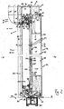
- Fig. 1 shows a horizontal cross section through a used as the outer end 8 of a building (not shown) door 10 with front door elements 11 in the form of a Haustblatts 12 and a door frame 14th
- the door frame 14 comprises a plurality Zargenholme 16, of which Fig. 1 only the vertically arranged Zargenholme the front door 10 are shown. You can see the lock-side Zargenholm 18 on the left in Fig. 1 and the band-side Zargenholm 20 on the right side of the Fig. 1 ,
- the lock-side Zargenholm 18 includes a first profile strip 22.
- the first profile strip 22 has a plurality of hollow profile elements 24, 24 ', 24 ", 26 on.
- the first hollow profile element 24, 24 ', 24 " is formed larger than the second hollow profile element 26.
- the first hollow profile element 24, 24', 24" can, as in FIG Fig. 1 shown by dash-dotted lines, in different sizes (hollow profile elements 24, 24 ', 24 "), depending on the need and construction of the masonry, are made.
- the second hollow profile element 26 has an abutment mechanism 30 for a lock 31 arranged on the front door leaf 12.
- the two hollow profile elements 24, 26 are preferably made of a metal, namely here a light metal, more precisely an aluminum alloy.
- the hollow profile elements 24, 24 ', 24 ", 26 are connected to one another via a plurality of connecting webs 32, 34.
- the connecting webs 32, 34 are made of fiber-reinforced plastic material 35.
- a carbon fiber composite material serves as a fiber-reinforced plastic material 35.
- a first connecting web 32 has a folded area shape 32b a bevelled or curved shape, wherein the slope reinforces toward the outer region 36 of the front door 10.
- a second connecting web 34 which is located on the wall side of the door frame 14, has a straight profile web, which is flush with the wall-side profile walls of the hollow profile elements 24, 24 ', 24 ", 26 extends.
- a first cavity 38 which is formed by the connection of the hollow profile elements 24, 24 ', 24 ", 26 with the connecting webs 32, 34, is foamed with an insulating material 39, such as foam insulation, in particular PU foam.
- the connecting webs 32, 34 have at their ends first dovetail-like projections 40 with which the connecting webs 32, 34 are positively engaged with trapezoidal groove formations on the hollow profile elements 24, 24 ', 24 ", 26.
- the first hollow profile element 24, 24 ', 24 "comprises a first groove 42, into which a first seal 44 can engage.
- the first seal 44 serves as an outer seal and engages on an outer edge region of the front door leaf 12.
- the band-side frame member 20 is formed by a second profile strip 46, which is formed substantially identical to the first profile strip 22.
- a second profile strip 46 is formed substantially identical to the first profile strip 22.
- One difference is that in the second hollow profile element 26 of the second profile strip 46 as a fitting 47 no thrust mechanism 30, but a first part 48 of a pivot mechanism 50, which is designed as a door hinge 51 is located.
- the pivoting mechanism 50 includes a concealed hinge system, as more particularly disclosed in the German patent application DE 10 2009 004 210.5-23 is described. This patent application is incorporated by reference into the present application. It is expressly made to this non-prepublished German patent application for more details of the door hinge 51.
- the front door leaf 12 has, on the lock side, a door latch 54 arranged on an inner region 52 and on the outer region 36 a rosette 55. In embodiments not shown, a front door handle is provided.
- the front door leaf 12 has as a supporting or supporting element on a door leaf frame 57 formed of a plurality of door leaf frame beams 56.
- the door leaf frame spars 56 are formed from further profile strips 58, 58a. More accurate the front door leaf 12 includes a third profile strip 58 on the lock side and a fourth profile strip 58 a on the hinge side.
- the third profile strip 58 forms a lock-side end face 59 of the front door leaf 12 and comprises a plurality of profile areas 60, 62.
- a first profile area 60 and a second profile area 62 are provided.
- the first profile area 60 is in form engagement with the second profile area 62.
- the second profile area 62 is formed from a light metal, namely an aluminum alloy, and has a lock receiving area for receiving the lock 31. It includes a second groove 66 which receives a second seal 68.
- the first profile region 60 of the third profile strip 58 has a first and a second strip element 74, 76.
- the first strip element 74 is larger than the second strip element 76.
- the first strip element 74 comprises two second dovetail-like projections 78 with which the two profile regions 60, 62 are fastened to one another in a form-fitting manner.
- the first strip element 74 Towards the outside area 36 of the front door leaf 12, the first strip element 74 has a third groove 80, by means of which the first strip element 74 encloses a first plate 82 in the form of a motif plate 83 of the front door leaf 12.
- the motif plate 83 essentially forms a first broad side 84 of the front door leaf 12.
- the first plate 82 is bent in the area in which it is enclosed by the first strip element 74 via the third groove 80 to the interior 86 of the Haustblatts 12.
- the first strip element 74 has a rounding 88 in a folded region 89 and thus forms a convex end region 90.
- the front door leaf 12 further comprises a second plate 92 in the form of a cover plate 94, which essentially forms a second broad side 96 of the Haustblatts 12.
- the second plate 92 encloses and is supported by the second profile region 62.
- the third profile strip 58 forms a spacer device 98, which holds the two plates 84, 96 forming the broad sides 84, 96 spaced. She forms with the plate 82 a box 100 of a box-lid construction 102 which is closed by the second plate 92 as a lid 104.
- a fourth groove 106 In the rounding 88 is a fourth groove 106. In this fourth groove 106, a third seal 108 is introduced.
- the front door panel 12 further includes a thermal insulation device 112 to thermally isolate the exterior 36 from the interior 52.
- the thermal insulation device 112 usually has a plurality of insulating material layers 114 or insulation layers.
- the Dämmstofflagen 114 are part of a door panel 115 for the front door leaf 12th
- the first strip element 74 and the second strip element 76 of the third profile strip 58 are positively connected to each other.
- the first strip element 74, the second strip element 76 and the second profile region 62 form a recess 116, in which one of the insulating material layers 114 is positively received and held, which is formed by a vacuum insulation panel 118.
- this vacuum insulation panel has a silicic acid anhydride 120 in the form of pyrogenic or nanoporous silica 122.
- the band-side frame member 20 is essentially formed by the fourth profile strip 58 a, which is identical to the third profile strip 58 and forms the band-side end face 124.
- the second profile region 62 of the fourth profile strip 58a does not have the counter-bearing mechanism 30 in its interior, but rather a band-receiving region 126 for a second part 128 of the swivel mechanism 50.
- the pivot mechanism 50 has a hinge formed by the door hinge 51, which connects the second hollow profile element 26 of the second profile strip 48 with the second profile region 62 of the fourth profile strip 58a.
- the lock 31 has one or more catch 132, which engages in a corresponding Schnäpperness 134 of the abutment mechanism 30 in the second hollow profile element 26 of the first profile strip 22.
- a multiple locking device (not shown) provided with a plurality of bars that can be actuated by a key or the like or a motor lock for personal identification for locking and unlocking the front door.
- the first broad side 84 is smaller, in particular narrower than the second broad side 96.
- the fold region 89 with the rounding 88 or in an alternative embodiment, not shown, of a bevel is provided as a transition from the narrow first broad side 84 to the broader second broad side 96 .
- the vacuum insulation panel 96 is formed as a package 136 and extends in the interior 86 of the Haustblatts 12 parallel to the two broad sides 84, 96th
- the arrangement of the vacuum insulation panel 96 results in two second cavities 138, which are foamed with a foam insulating material 140 forming a further insulating material layer 114.
- the foam insulating material 140 also foams a fifth groove 142 in the first strip element 74, which opens toward the interior 86 for the purpose of positive reception of the thermal insulation device 112.
- the thermal insulation device 112 has further components, which are formed from fiber-reinforced plastic material 35 and connect the thermal insulation areas that are in contact with the outer region 36, with areas that are in contact with the inner region 52.
- the fiber-reinforced plastic material 35 has a very low thermal conductivity, whereby thermal bridges can be avoided, i. It acts as a thermally insulating material.
- the cavity 38 is additionally foamed by a foam insulation 142, so as to increase the thermal insulation capacity of the door frame 14 even further.
- the vacuum insulation panel 118 acts as a thermal insulation panel.
- the vacuum insulation panel 118 is formed by flowable nanoporous insulating material 148, which has been filled as a particle medium in a film 150, which defines the basic shape of the package 136 as a shell 152 or envelope. Subsequently, the shell 152 is evacuated to press firmly against the particle medium. The package 136 thus has a vacuum.
- Such a thermal insulation board has a much higher thermal insulation value than conventional foam insulation. Therefore, the thermal insulation function of the front door leaf 12 is increased by a multiple by the use of such a thermal insulation board.
- the first strip element 74 of the first profile area 60 in the front door leaf 12 is likewise formed from fiber-reinforced plastic material 35. This prevents on the one hand because of the low thermal conductivity of this material, a thermal bridge, on the other hand it makes the front door leaf 12 due to the mechanical properties of the fiber-reinforced plastic material 35 particularly in this area resistant. Especially this area is particularly stressed during operation.
- the first connecting web 32 of the frame spar 16 is formed from the fiber-reinforced plastic material 35, the total area of the front door 10 is extremely robust and resistant.
- the first strip element 74 of the third profile strip 58 and the first connecting web 32 of the Zargenholmes 16 are rounded - rounded 88 - and have a mutually complementary shape.
- This shape is designed such that the front door leaf 12 can be made thicker without the front door leaf 12 canted to the frame member 16.
- the door gap 156 are widened.
- this door gap 156 can be kept narrow here due to the improved design, which contributes to the thermal insulation.
- the rounded shape also reduces the stress on the third seal 92 attached to the first ledge member 74 in the fourth groove 90.
- the front door 10 has between the Zargenholm 16 and the front door leaf 12 has three seals 44, 68, 108. This results in the door gap 156 in the closed state of the front door 10, two air chambers 1158, 160. By a plurality of air chambers, it is possible to keep the convection of the air low, i. to form a convection barrier, thus hindering the heat exchange. As a result, the thermal insulation capacity of the front door 10 is further improved.
- the rounding 88 of the first strip element 74 of the third profile strip 58 also causes the front door leaf 12 looks elegant and filigree. It is therefore possible, even thick doors that can absorb a large amount of thermal insulation materials in their interior by their thickness, to look elegant and filigree.
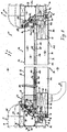
- Fig. 2 shows a vertical cross section through the front door 10 with the front door leaf 12 and the door frame 14th
- the front door 10 has a threshold profile 164 of a door sill 166 instead of a frame spar 16.
- the door sill 166 comprises a third hollow profile element 168 and a Bodeneinstand 170.
- the third hollow profile element 168 and the Bodeneinstand 170 are fastened by a plurality of fasteners 172, in particular screws, to each other.
- the third hollow profile element 168 is embedded in the bottom 174 and formed in the example shown here from the fiber-reinforced plastic material 35.
- the hollow profile element 168 has, in the illustrated example, two hollow chambers 176, 178, which may be reinforced by metal cantilevers 180.
- the bottom recess 170 comprises an outside area 182 and an inside area 184. Both areas 182, 184 are formed of metal, in particular light metal, such as an aluminum alloy.
- the outside area 182 has a metal profile element with a projection area 188 with a projection 190 to which a fourth seal 194 attached to the lower front side 192 of the front door leaf 12 abuts.
- the outside area 182 and the inside area 184 of the bottom fence 170 are connected to each other by a connecting piece 196.
- the connector 196 has a profile shaped like a dog bone.
- the fastening elements 172 are covered with a web 198, which is preferably formed from the fiber-reinforced plastic material 35.
- the front door leaf 12 also has the second seal 68 at the bottom area 176.
- the in Fig. 1 is shown, the vertical portion of the front door 10 in the bottom portion 176 only two instead of three seals.
- first strip element 74 in the bottom region 176 does not surround the first plate 82, but here it overlies the first strip element 74.
- the use of the fiber-reinforced plastic material 35 is in the bottom portion 176 of advantage, since here too, depending on the load, large forces can act, on the other hand, the avoidance of thermal bridges is useful here.
- the floor area 176 is thereby more robust and resistant, yet thermally insulated.
- both the outside area 182 and the inside area 184 of the bottom fence 170 are fastened, each with its own fastening element 172, to the third hollow profile element 168.
- the protrusion 190 of the outside area 182 avoids the ingress of dirt or precipitate over the door sill 166.
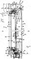
- Fig. 3 and Fig. 4 show a second embodiment of the front door 10 with the front door leaf 12 and the door frame 14, wherein Fig. 3 a horizontal cross section and Fig. 4 a vertical cross section through the front door 10 shows.
- the first differs from the second embodiment only in that no second strip element 76 is present in the first profile area 60 of the third profile strip 58.
- the vacuum insulation panel 96 is not held in a form-fitting manner between the first profile area 60 and the second profile area 62, but is preferably fastened to the second profile area 62 in a material-locking manner. This simplifies production and makes it more cost effective, since a strip element has to be produced less.
- the two embodiments differ, as in FIG Fig. 4 shown in that the connecting piece 196 is not shaped like a dog bone, but is provided with an annular ridge portion 200.
- the connector 196 thus fills the entire space 202 between the outside area 182 and the inside area 186 of the bottom panel 170, thus making the structure even more stable.
- connection profile 206 has a support portion 210 which is complementary to the rounding 88 and is supported thereon.
- the support region 210 supports a protruding lower edge region 212 of the motif plate 83.
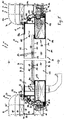
- Fig. 5 and Fig. 6 show a third embodiment of the front door 10 with the front door leaf 12 and the door frame 14, wherein Fig. 5 a horizontal and Fig. 6 a vertical cross section through the front door 10 shows.
- the third embodiment differs from the other two embodiments in that the two profile regions 60, 62 of the third profile strip 58 are formed as regions of a one-piece hollow profile 214, which is formed entirely from the fiber-reinforced plastic material 35.
- the vacuum insulation panel 118 is smaller than in the other two embodiments and attached via an adhesive connection 216 to the second profile portion 62. Because no metallic and therefore no good thermal conductivity Material is more present in the interior 86 of the Haustblatts 12, insulation material can be saved, which makes the structure cheaper.
- the Bodeneinstand 170 is integrally formed of fiber reinforced plastic material 35.
- the fasteners 172 are only individually covered with a small, also made of fiber-reinforced plastic material 35 cover 218.
- the projection 190 is additionally reinforced and sealed with an outer seal 220.
- the material used contributes to a better thermal insulation and greater robustness of the Bodeneinstands 170.
- the fiber reinforced plastic material 35 has certain advantages in terms of its resistance and thermal insulation ability to metal materials. In most cases, it is much more expensive. Therefore, it is advantageous if various embodiments are available, which have different proportions of the respective material. Thus, the client can decide after weighing the cost-benefit factor for a suitable solution for him.
- the connecting webs 32, 34 and the strip elements 74, 76 and the profile region 62 of the third profile strip 58 are formed. Furthermore, also in Pultrusionstechnik the areas 182, 184 of Bodeneinstands 170, the connecting piece 196 and a web 198 are formed.
- reinforcing fibers are impregnated with resin either in an open or a closed process.
- the reinforcing fibers are guided via a dipping roller from their positions into a resin trough (also impregnated trough).
- a Kadier grid ensures the desired distribution of the fibers in the later profile. These are soaked in a resin pan with resin and go through several preform stations, which bring the fiber resin mixture closer and closer to the desired, final shape.
- the entire reinforcing fibers only come into contact with the resin in the forming tool - but then at elevated pressure.
- thermosetting plastic is continuously cured at temperatures between 100 and 200 ° C (depending on the material) (hot curing process). For large-volume profiles, care should be taken to ensure that the heat distribution is as constant as possible in order to prevent cracks.
- the cured profile is then sawn into arbitrarily long pieces. The entire process is performed by a drawing tool z. B. in the form of a caterpillar take-off or reversing hydraulic grippers in motion, which pulls the finished profile and thus the fibers together with the resin and the reinforcing material from the curing tool.
- the hollow profile elements 24, 26 and the second profile portion 62 of the third profile strip 58 produced by forming are the generic term for all manufacturing processes in which metals are purposefully plastically converted into another shape.
- the volume before and after the forming is the same; the mass and cohesion of the material are retained during forming.
- cold and hot forming recrystallization regularly occurs, which counteracts solidification of the material. Cold forming refers to a deformation below the recrystallization temperature. In her case, it comes to a solidification with reduced toughness.
- the two hollow profile elements 24, 26 are connected via form engagement with connecting webs 32, 34 to the first profile strip 22, which forms an element of the door frame 14.
- the resulting first cavity between the two Hollow profile elements 24, 26 and the connecting webs 32, 34 is foamed with an insulating material 39.
- first and second strip elements 74, 76 are connected to the first profile area 60 of the third profile strip 58.
- the first profile region 60 thus formed is connected to the second profile region 62 to form the third profile strip 58 via a form engagement.
- one of the two plates 82, 92, e.g. the motif plate 83 mounted to form the box 100 of the box-lid construction 102.
- the vacuum insulation panel 118 is inserted, a foam insulation 140 is introduced, and then the box 100 is fitted with a second panel 92, e.g. closed in the form of a cover plate 94.
- a foam insulation 140 is introduced, and then the box 100 is fitted with a second panel 92, e.g. closed in the form of a cover plate 94.
- fittings such as the lock 31, the door hinges 51, the abutment mechanism 30, the swing mechanism 50, the door latch 54 and the rosette 55 are attached.
- seals 44, 68, 108, 194 are inserted into the corresponding grooves. This step can also be done before cutting the raw profiles.
- the door is delivered to the construction site and installed there.
Landscapes
- Engineering & Computer Science (AREA)
- Civil Engineering (AREA)
- Structural Engineering (AREA)
- Securing Of Glass Panes Or The Like (AREA)
- Refrigerator Housings (AREA)
- Wing Frames And Configurations (AREA)
- Special Wing (AREA)
- Building Environments (AREA)
Description
- Die Erfindung betrifft eine Haustür für einen Außenabschluss eines Gebäudes mit wenigstens einer Profilleiste, wie sie aus der
DE 296 17 479 U1 , derEP 1 568 842 B1 sowie derEP 1 780 368 A2 bekannt ist. - Die
DE 296 17 479 U1 offenbart eine Haustür mit einem Haustürblatt, bei dem aus Aluminiumprofilen ein Türblattrahmen gefertigt ist und an dem Türblattrahmen Motivplatten angebracht sind. Zwischen den Motivplatten können Füllelemente zur Wärme- und/oder Schallisolierung vorgesehen sein. - In der
EP 1 568 842 B1 ist ein Haustürblatt für eine Haustür beschrieben, das einen Türblattrahmen aus Leichtmetallprofilen ausweist. An dem Türblattrahmen wird eine Sandwichplatte als Türfüllung gehalten, die aus einer Motivplatte und einer Abschlussplatte und Dämmmaterial dazwischen gebildet ist. - Die
EP 1 780 368 A2 offenbart eine Haustür mit einem Haustürblatt mit Türblattrahmen, in dem eine Türfüllung eingesetzt ist, die eine Motivplatte aufweist. - Allen oben beschriebenen Haustüren ist gemein, dass sie in der Regel so gefertigt werden, dass ein meist umlaufender Türblattrahmen vorgesehen ist, an dem die Beschläge angeordnet sind. Der Türblattrahmen ist aus einem Leichtmetall wie beispielsweise einer Aluminiumlegierung gebildet.
- In oder an diesen Türblattrahmen wird dann eine Türblattfüllung eingesetzt. Als Türblattfüllung kommen dazu Sandwichplatten in Frage. Diese Sandwichplatten weisen Motivplatten, Abschlussplatten und Dämmmaterial auf.
- Auf dem Haustürmarkt finden sich viele Firmen, die sich ausschließlich auf die Herstellung von Türblattfüllungen spezialisiert haben, da der Aufbau eines Haustürblatts aus einem Türblattrahmen und einer Türblattfüllung die übliche Bauweise bei Haustüren darstellt.
- Sandwichplatten werden dabei meist in den Türblattrahmen eingeführt, wie das beispielsweise in der
DE 296 17 479 U1 offenbart ist. - Dabei weist der Türblattrahmen zusätzlich Verbindungsstege aus schlecht Wärme leitendem Material auf, um Wärmebrücken zu vermeiden.
- Solche Haustüren haben sich in der Praxis bewährt, sie weisen jedoch einige verbessungswürdige Nachteile auf.
- Haustüren haben eine Vielzahl von Funktionen, die sie erfüllen müssen, u. a. sollten sie einen Wärmedämmschutz aufweisen.
- Haustüren, bei denen eine Sandwichplatte in einen Türblattrahmen aus Leichtmetall eingefügt wird, müssen zur Wärmedämmung zusätzlich mit Verbindungsstegen aus einem Material, das Wärme schlecht leitet, versehen werden. Dies ist in der Produktion aufwändig und erhöht die Kosten im Vergleich zu Türen, die solche Wärme dämmenden Maßnahmen nicht benötigen, wie etwa Innentüren.
- Die aus der
EP 1 568 842 B1 bekannten Haustüren, bei denen die Sandwichplatte auf den Türblattrahmen aufgelegt wird, bieten insofern Vorteile, als hier keine große Anzahl an Verbindungsstegen aus dem schlecht Wärme leitenden Material nötig sind. Sie haben jedoch ebenfalls einen Nachteil, nämlich den, dass eine Abdeckleiste vorgesehen ist, die als Abdeckung und Befestigung der Sandwichplatte verwendet wird. Die Abdeckleiste ist als Klipsprofil gebildet, d.h. sie muss zu einem gewissen Grad flexibel sein. Sämtliche Belastungen werden von dem Türblattrahmen aufgenommen. Belastungen an der Sandwichplatte könnten zu Beschädigungen oder Beeinträchtigungen der Optik führen. - Die Wärmedämmung wird dabei zu einem Großteil durch das Dämmmaterial der Sandwichplatte gewährleistet, deren Dicke zusätzlich zu der Rahmendicke zu einer hohen Türblatttiefe führt.
- Haustüren sollten in ihrem Aufbau aber derart gestaltet sein, dass sie äußeren Einflüssen wie beispielsweise einem Einbruchsversuch oder auch Naturgewalten eine möglichst hohe Widerstandskraft entgegensetzen, um so eine Beschädigung zu verhindern oder zumindest zu erschweren. Dazu tragen flexible Bauteile an der Haustür aber nicht bei.
- Hauptargument für eine Haustür bleibt weiterhin das Design, so dass Haustüren ein hochwertiges optisches Erscheinungsbild haben sollten.
- Weiter sollten Haustüren eine möglichst hohe Wärmedämmfähigkeit aufweisen, da sich Schwachstellen, die einen höheren Wärmeabfluss aus dem Gebäude zulassen als ihre direkte Umgebung, negativ auf die Energieeffizienz des Gebäudes auswirken. Solche Schwachstellen sind generell am Dach, den Fenstern und Außentüren zu finden. Deshalb sollten gerade diese Bauelemente eine besonders gute Wärmedämmfähigkeit aufweisen.
- Jedoch gerade bei dem Aufbau, bei dem eine Sandwichplatte in einen Türblattrahmen eingelegt wird, ist eine solche Wärmedämmung aufwändig, da hier zusätzliche Elemente vorgesehen werden müssen, um diese Funktion zu erfüllen. Bei Auflage auf den Rahmen wird der Rahmenaufbau wesentlich einfacher, jedoch wird für hohe Wärmedämmung eine große Türblattdicke benötigt, was für die Öffnungs- und Schließfunktion, aber auch für das optische Erscheinungsbild nachteilig sein kann.
-
WO 2004/065742 A2 offenbart einen Türblattrahmen mit einem Hohlprofilelement mit faserverstärktem Kunststoffmaterial. - In
WO 01/04448 A1 -
CH 656 669 A5 - In
DE 298 19 925 U1 ist eine Zargenprofilleiste aus faserverstärktem Kunststoffmaterial beschrieben. -
US 5 584 157 A zeigt eine aus mehreren Profilelementen aufgebaute Türzarge, wo die Befestigungspfosten und die Überdeckungen aus faserverstärktem Kunststoffmaterial bestehen. - Aufgabe der Erfindung ist es daher, eine Haustür zu schaffen, die eine hohe Widerstandskraft und eine möglichst hohe Wärmedämmfähigkeit hat.
- Die Aufgabe wird mit einer Haustür mit den Merkmalen des Patentanspruchs 1 gelöst.
- Vorteilhafte Ausgestaltungen der Erfindung sind Gegenstand der Unteransprüche.
- Um die Haustür für einen Außenabschluss eines Gebäudes besonders widerstandsfähig zu machen, ist bei der Erfindung zumindest für Profilbereiche, die insbesondere einen Rahmenaufbau oder dergleichen bilden, ein Material zu verwenden, das nur sehr schlecht die Wärme leitet. Hierzu schlägt die Erfindung vor, dass wenigstens eine Profilleiste, die sich an der Haustür befindet, wenigstens einen Profilbereich aufweist, der aus einem faserverstärktem Kunststoffmaterial gebildet ist.
- Faserverstärktes Kunststoffmaterial ist ein Werkstoff, der aus Verstärkungsfasern und einer Kunststoffmatrix besteht. Die Fasern können beispielsweise Glasfasern oder auch Kohlenstofffasern sein, es sind jedoch auch andere Faserarten bekannt. Die Matrix umgibt die Fasern, die durch Adhäsiv- und/oder Kohesivkräfte an die Matrix gebunden sind.
- Die Verstärkungsfasern zeichnen sich dadurch aus, dass sie hohe spezifische Festigkeiten und Steifigkeiten aufweisen. Ohne den Matrixwerkstoff sind diese hohen spezifischen Festigkeiten und Steifigkeiten allerdings nicht nutzbar, erst durch eine geeignete Kombination von Faser- und Matrixwerkstoff entsteht ein neuer Konstruktionswerkstoff.
- Die mechanischen und thermischen Eigenschaften dieses Konstruktionswerkstoffes können über eine Vielzahl von Parametern individuell eingestellt werden. So können unterschiedliche Faser- bzw. Matrixmaterialien verwendet werden, der Faserwinkel angepasst werden, die Schichtreihenfolge verändert werden oder auch der Faservolumenanteil je nach gewünschten Eigenschaften vergrößert oder verkleinert werden. Hierdurch lassen sich die Profilleisten kraftflussgerecht maßschneidern.
- Neben der Festigkeit weisen Kunststoffmaterialien generell eine geringe Wärmeleitfähigkeit auf und können daher in Zusammenhang mit weiteren Wärmedämmeinrichtungen eine effektive Wärmedämmung bereitstellen.
- Das faserverstärkte Kunststoffmaterial kann für eine Anwendung in einem Profilbereich einer Haustür vorteilhaft in Pultrusionstechnik hergestellt werden, da durch diese Technik Profile auch in komplizierten Formen gefertigt werden können.
- Vorzugsweise ist das faserverstärkte Kunststoffmaterial ein Kohlenfaserverbundwerkstoff, der sich im Vergleich zu Faserverbundwerkstoffen mit anderen Fasertypen durch ein geringeres Gewicht auszeichnet. Dies ist insbesondere bei Haustüren von Vorteil, die oft besonders wuchtig und schwer sind. Der Einsatz von Leichtmaterialien verringert das Gewicht und vereinfacht den Betrieb der Haustür. Auch lassen sich Klemm- und Verletzungsgefahren beim Zuschlagen der Haustür verringern, da einerseits ein geringer Impuls auftritt, andererseits Profilleisten in ihrer Steifigkeit in Quer- und Längsrichtung angepasst werden können.
- Die Haustür weist ein Haustürblatt mit einem Türblattrahmen auf, wobei der Türblattrahmen wenigstens einen durch eine der Profilleisten gebildeten Türblattrahmenholm aufweist. Dabei ist wenigstens ein Teilprofilbereich wenigstens eines Türblattrahmenholms aus dem faserverstärkten Kunststoffmaterial gefertigt.
- Wenigstens die vertikal anzuordnende Türblattrahmenholme sind ganz oder teilweise aus faserverstärktem Kunststoffmaterial gefertigt. An ihnen wirkt nicht nur im Falle eines äußeren Einflusses wie eines Einbruchs, sondern generell im Betrieb die größte Kraft, weswegen in diesem Bereich ein Material mit hoher Steifigkeit und Festigkeit bevorzugt verwendet wird. Beispielsweise werden in die vertikalen Türblattrahmenholme Kräfte über Türbänder, Schlösser oder sonstige Beschläge eingeleitet.
- Vorzugsweise umfasst die Profilleiste, die einen Türblattrahmenholm bildet, einen als Hohlprofil ausgebildeten zweiten Profilbereich, der entweder einstückig mit dem ersten Profilbereich aus dem faserverstärkten Kunststoffmaterial gebildet ist, oder der aus einem Metall, insbesondere Leichtmetall, mehr insbesondere eine Aluminiumlegierung, gebildet ist. Dieser zweite Profilbereich ist vorzugsweise an dem ersten Profilbereich befestigt, mehr insbesondere ist er formschlüssig daran befestigt. Einige besonders gut geeignete hochwertige faserverstärkte Kunststoffmaterialien, wie z.B. CFK, sind im Vergleich zu den im Haustürbau bisher verwendeten Metalllegierungen relativ teuer. Deshalb ist es günstig, nur einen Teil der Profilleisten in Pultrusionstechnik aus diesem Material zu fertigen. Dort wo jedoch die Widerstandskraft der Haustür den Kostenfaktor überwiegt, ist es günstig, die gesamte Profilleiste aus dem faserverstärkten Kunststoffmaterial zu fertigen, da die Stellen, an denen zwei unterschiedliche Materialien aneinander befestigt sind, Schwachstellen bilden können. Außerdem lässt sich so ein sehr kompakter, leichtgewichtiger, aber dennoch optischer Türaufbau mit hohem Dämmwert schaffen.
- Vorzugsweise bildet der aus faserverstärktem Kunststoffmaterial gebildete Profilbereich der Türblattrahmenholme zumindest an der schlossseitigen Stirnseite des Haustürblatts einen abgeschrägten oder abgerundeten Falzbereich. Dies hat insbesondere den technischen Effekt, dass die Haustür trotz ihrer robusten und stabilen Eigenschaften filigran wirkt. Durch die Abrundung wirkt die Haustür wesentlich leichter und filigraner. Sie kann außerdem wesentlich dicker aufgebaut werden, ohne dass sich das Haustürblatt im Betrieb der Haustür bei schmalen Türspalten an der Türzarge verkantet. Durch die Abschrägung bzw. Abrundung des Falzbereiches wirkt die Haustür auch bei dickerer Ausbildung leicht und filigran. Türspaltmaße können verringert werden, so dass ein Wärmeverlust durch Türspalte verringerbar ist und ein qualitativ hochwertiges Aussehen geschaffen wird.
- Ausführungsbeispiele der Erfindung werden nachfolgend anhand der beigefügten Zeichnungen näher erläutert. Darin zeigt:
-
Fig. 1 einen Horizontalschnitt durch eine erste Ausführungsform einer Haustür mit Haustürblatt und Türzarge; -
Fig.2 einen Vertikalschnitt durch die erste Ausführungsform der Haustür; -
Fig. 3 einen Horizontalschnitt durch eine zweite Ausführungsform der Haustür mit Haustürblatt und Türzarge; -
Fig. 4 einen Vertikalschnitt durch die zweite Ausführungsform der Haustür; -
Fig. 5 einen Horizontalschnitt durch eine dritte Ausführungsform der Haustür mit Haustürblatt und Türzarge und -
Fig. 6 einen Vertikalschnitt durch die dritte Ausführungsform der Haustür. -
Fig. 1 zeigt einen horizontalen Querschnitt durch eine als Außenabschluss 8 eines Gebäudes (nicht gezeigt) verwendete Haustür 10 mit Haustürelementen 11 in Form eines Haustürblatts 12 und einer Türzarge 14. - Die Türzarge 14 umfasst mehrere Zargenholme 16, von denen in
Fig. 1 nur die vertikal anzuordnenden Zargenholme der Haustür 10 gezeigt sind. Zu sehen sind der schlossseitige Zargenholm 18 auf der linken Seite inFig. 1 und der bandseitige Zargenholm 20 auf der rechten Seite derFig. 1 . - Der schlossseitige Zargenholm 18 umfasst eine erste Profilleiste 22. Die erste Profilleiste 22 weist mehrere Hohlprofilelemente 24, 24', 24", 26 auf.
- Das erste Hohlprofilelement 24, 24', 24" ist größer als das zweite Hohlprofilelement 26 ausgebildet. Das erste Hohlprofilelement 24, 24', 24" kann, wie in
Fig. 1 durch strichpunktierte Linien gezeigt, in verschiedenen Größen (Hohlprofilelemente 24, 24', 24"), je nach Bedürfnis und Bauweise des Mauerwerks, gefertigt werden. - Das zweite Hohlprofilelement 26 weist einen Gegenlagermechanismus 30 für ein an dem Haustürblatt 12 angeordnetes Schloss 31 auf. Die beiden Hohlprofilelemente 24, 26 sind bevorzugt aus einem Metall, nämlich hier einem Leichtmetall, genauer einer Aluminiumlegierung, gefertigt.
- Die Hohlprofilelemente 24, 24', 24", 26 sind über mehrere Verbindungsstege 32, 34 miteinander verbunden. Die Verbindungsstege 32, 34 sind aus faserverstärktem Kunststoffmaterial 35 gefertigt. Als faserverstärktes Kunststoffmaterial 35 dient ein Kohlenfaserverbundwerkstoff. Ein erster Verbindungssteg 32 weist als Falzbereichsform 32b eine abgeschrägte beziehungsweise gekrümmte Form auf, wobei sich die Schräge zum Außenbereich 36 der Haustür 10 hin verstärkt. Ein zweiter Verbindungssteg 34, der sich auf der Mauerseite der Türzarge 14 befindet, weist einen geradlinigen Profilsteg auf, der sich bündig zu mauerseitigen Profilwänden der Hohlprofilelemente 24, 24', 24", 26 erstreckt.
- Ein erster Hohlraum 38, der durch die Verbindung der Hohlprofilelemente 24, 24', 24", 26 mit den Verbindungsstegen 32, 34 entsteht, ist mit einem Dämmmaterial 39, wie Schaumdämmstoff, insbesondere PU-Schaum, ausgeschäumt.
- Die Verbindungsstege 32, 34 weisen an ihren Enden erste schwalbenschwanzartige Vorsprünge 40 auf, mit denen die Verbindungsstege 32,34 formschlüssig im Eingriff mit Trapeznutausbildungen an den Hohlprofilelementen 24, 24', 24", 26 sind.
- Das erste Hohlprofilelement 24, 24', 24" umfasst eine erste Nut 42, in die eine erste Dichtung 44 eingreifen kann. Die erste Dichtung 44 dient als Außenabschluss und greift an einem Außenkantenbereich des Haustürblatts 12 an.
- Der bandseitige Zargenholm 20 wird durch eine zweite Profilleiste 46 gebildet, die im Wesentlichen identisch zu der ersten Profilleiste 22 geformt ist. Ein Unterschied besteht darin, dass sich in dem zweiten Hohlprofilelement 26 der zweiten Profilleiste 46 als Beschlag 47 kein Gegenlagermechanismus 30, sondern ein erster Teil 48 eines Schwenkmechanismus 50, der als Türband 51 ausgebildet ist, befindet.
- Der Schwenkmechanismus 50 umfasst ein verdeckt liegendes Bandsystem, wie es genauer in der deutschen Patentanmeldung
DE 10 2009 004 210.5-23 beschrieben wird. Diese Patentanmeldung wird durch Bezugnahme in die hiesige Anmeldung inkorporiert. Es wird für weitere Einzelheiten des Türbands 51 ausdrücklich auf diese nicht vorveröffentlichte deutsche Patentanmeldung verwiesen. - Das Haustürblatt 12 weist schlossseitig eine an einem Innenbereich 52 angeordnete Türklinke 54 und an dem Außenbereich 36 eine Rosette 55 auf. Bei nicht dargestellten Ausführungsformen ist auch ein Haustürgriff vorgesehen.
- Das Haustürblatt 12 weist als tragendes oder stützendes Element einen aus mehreren Türblattrahmenholmen 56 gebildeten Türblattrahmen 57 auf. Die Türblattrahmenholme 56 sind aus weiteren Profilleisten 58, 58a gebildet. Genauer umfasst das Haustürblatt 12 schlossseitig eine dritte Profilleiste 58 und bandseitig eine vierte Profilleiste 58a. Die dritte Profilleiste 58 bildet eine schlossseitige Stirnseite 59 des Haustürblatts 12 und umfasst mehrere Profilbereiche 60, 62. In dem dargestellten Beispiel ist ein erster Profilbereich 60 und ein zweiter Profilbereich 62 vorgesehen. Der erste Profilbereich 60 ist in Formeingriff mit dem zweiten Profilbereich 62. Der zweite Profilbereich 62 ist aus einem Leichtmetall, nämlich einer Aluminiumlegierung gebildet und weist einen Schlossaufnahmebereich zur Aufnahme des Schlosses 31 auf. Er umfasst eine zweite Nut 66, die eine zweite Dichtung 68 aufnimmt.
- Der erste Profilbereich 60 der dritten Profilleiste 58 weist ein erstes und ein zweites Leistenelement 74, 76 auf. Das erste Leistenelement 74 ist dabei größer als das zweite Leistenelement 76. Das erste Leistenelement 74 umfasst zwei zweite schwalbenschwanzartige Vorsprünge 78, mit denen die beiden Profilbereiche 60, 62 formschlüssig aneinander befestigt sind.
- Zum Außenbereich 36 des Haustürblattes 12 hin gerichtet weist das erste Leistenelement 74 eine dritte Nut 80 auf, mittels der das erste Leistenelement 74 eine erste Platte 82 in Form einer Motivplatte 83 des Haustürblatts 12 umschließt. Die Motivplatte 83 bildet im Wesentlichen eine erste Breitseite 84 des Haustürblatts 12.
- Die erste Platte 82 ist in dem Bereich, in dem sie von dem ersten Leistenelement 74 über die dritte Nut 80 umschlossen wird, zum Inneren 86 des Haustürblatts 12 umgebogen. Das erste Leistenelement 74 weist eine Abrundung 88 in einem Falzbereich 89 auf und bildet somit einen konvexen Stirnbereich 90.
- Das Haustürblatt 12 weist weiter eine zweite Platte 92 in Form einer Deckplatte 94 auf, die im Wesentlichen eine zweite Breitseite 96 des Haustürblatts 12 bildet. Die zweite Platte 92 umschließt den zweiten Profilbereich 62 und wird von diesem gestützt.
- Die dritte Profilleiste 58 bildet eine Abstandshalteeinrichtung 98, die die beiden die Breitseiten 84, 96 bildenden Platten 82, 92 beabstandet hält. Sie bildet mit der Platte 82 einen Kasten 100 einer Kasten-Deckel-Konstruktion 102, die durch die zweite Platte 92 als Deckel 104 verschlossen wird.
- In der Abrundung 88 befindet sich eine vierte Nut 106. In diese vierte Nut 106 ist eine dritte Dichtung 108 eingebracht.
- Das Haustürblatt 12 weist weiter eine Wärmedämmeinrichtung 112 auf, um den Außenbereich 36 von dem Innenbereich 52 thermisch zu isolieren. Die Wärmedämmeinrichtung 112 weist meist mehrere Dämmstofflagen 114 oder Dämmstoffschichten auf. Die Dämmstofflagen 114 sind Teil einer Türfüllung 115 für das Haustürblatt 12.
- Das erste Leistenelement 74 und das zweite Leistenelement 76 der dritten Profilleiste 58 sind formschlüssig miteinander verbunden. Das erste Leistenelement 74, das zweite Leistenelement 76 und der zweite Profilbereich 62 bilden eine Aussparung 116, in der eine der Dämmstofflagen 114 formschlüssig aufgenommen und gehalten ist, die durch eine Vakuumdämmplatte 118 gebildet wird. Diese Vakuumdämmplatte weist in der dargestellten Ausführungsform ein Kieselsäureanhydrid 120 in Form pyrogener oder nanoporöser Kieselsäure 122 auf.
- Der bandseitige Zargenholm 20 ist im Wesentlichen durch die vierte Profilleiste 58a gebildet, die identisch zu der dritten Profilleiste 58 gebildet ist und die bandseitige Stirnseite 124 bildet. Als einziger Unterschied weist der zweite Profilbereich 62 der vierten Profilleiste 58a in seinem Inneren nicht den Gegenlagermechanismus 30 auf, sondern einen Bandaufnahmebereich 126 für einen zweiten Teil 128 des Schwenkmechanismus 50.
- Der Schwenkmechanismus 50 weist ein durch das Türband 51 gebildetes Drehgelenk auf, das das zweite Hohlprofilelement 26 der zweiten Profilleiste 48 mit dem zweiten Profilbereich 62 der vierten Profilleiste 58a verbindet. Das Schloss 31 weist einen oder mehrere Schnäpper 132 auf, der oder die in eine entsprechende Schnäpperaufnahme 134 des Gegenlagermechanismus 30 in dem zweiten Hohlprofilelement 26 der ersten Profilleiste 22 einrastet. Weiter ist eine Mehrfachverriegelungseinrichtung (nicht dargestellt) mit mehreren Riegeln vorgesehen, die durch einen Schlüssel oder dergleichen oder ein Motorschloss nach Personenidentifikation zum Ver- und Entriegeln der Haustür betätigbar sind.
- Die erste Breitseite 84 ist kleiner, insbesondere schmäler als die zweite Breitseite 96. An den Stirnseiten ist als Übergang von der schmalen ersten Breitseite 84 zur breiteren zweiten Breitseite 96 der Falzbereich 89 mit der Abrundung 88 oder in einer alternativen, nicht dargestellten Ausführung einer Abschrägung vorgesehen. Die Vakuumdämmplatte 96 ist als Paket 136 ausgebildet und erstreckt sich im Inneren 86 des Haustürblatts 12 parallel zu den beiden Breitseiten 84, 96.
- Durch die Anordnung der Vakuumdämmplatte 96 entstehen zwei zweite Hohlräume 138, die mit einem eine weitere der Dämmstofflagen 114 bildenden Schaumdämmstoff 140 ausgeschäumt sind. Durch den Schaumdämmstoff 140 ist auch eine fünfte Nut 142 in dem ersten Leistenelement 74 ausgeschäumt, die sich zum Inneren 86 hin öffnend zwecks formschlüssiger Aufnahme der Wärmedämmeinrichtung 112 erstreckt..
- Die Wärmedämmeinrichtung 112 weist weitere Bauteile auf, die aus faserverstärktem Kunststoffmaterial 35 gebildet sind und die zur Wärmedämmung Bereiche, die mit dem Außenbereich 36 in Kontakt stehen, mit Bereichen, die mit dem Innenbereich 52 in Kontakt stehen, verbinden. Das faserverstärkte Kunststoffmaterial 35 weist eine sehr geringe Wärmeleitfähigkeit auf, wodurch Wärmebrücken vermieden werden können, d.h. es wirkt als thermisch isolierendes Material.
- In jedem Zargenholm 16 wird zusätzlich der Hohlraum 38 durch einen Schaumdämmstoff 142 ausgeschäumt, um so die Wärmedämmfähigkeit der Türzarge 14 noch weiter zu erhöhen. In dem Haustürblatt 12 wirkt zusätzlich zu dem Schaumdämmstoff 140 noch die Vakuumdämmplatte 118 als Wärmedämmplatte.
- Die Vakuumdämmplatte 118 ist durch fließfähiges nanoporöses Dämmmaterial 148 gebildet, das als Partikelmedium in einer Folie 150, die als Hülle 152 oder Umhüllung die Grundform für das Paket 136 vorgibt, eingefüllt worden ist. Anschließend wird die Hülle 152 evakuiert, um sie fest gegen das Partikelmedium zu pressen. Das Paket 136 weist somit ein Vakuum auf.
- Eine solche Wärmedämmplatte hat einen um ein vielfaches höheren Wärmedämmwert als herkömmlicher Schaumdämmstoff. Daher wird durch die Verwendung einer solchen Wärmedämmplatte die Wärmedämmfunktion des Haustürblattes 12 um ein Vielfaches gesteigert.
- Das erste Leistenelement 74 des ersten Profilbereichs 60 in dem Haustürblatt 12 ist ebenfalls aus faserverstärktem Kunststoffmaterial 35 gebildet. Dies verhindert zum Einen wegen der geringen Wärmeleitfähigkeit dieses Materiales eine Wärmebrücke, zum Anderen macht es das Haustürblatt 12 aufgrund der mechanischen Eigenschaften des faserverstärkten Kunststoffmaterials 35 besonders in diesem Bereich widerstandsfähig. Gerade dieser Bereich wird insbesondere im Betrieb stärker beansprucht.
- Da auch der erste Verbindungssteg 32 des Zargenholms 16 aus dem faserverstärkten Kunststoffmaterial 35 gebildet ist, ist der Gesamtbereich der Haustür 10 äußerst robust und widerstandsfähig.
- Das erste Leistenelement 74 der dritten Profilleiste 58 und der erste Verbindungssteg 32 des Zargenholmes 16 sind abgerundet gebildet - Abrundung 88 - und weisen eine zueinander komplementäre Form auf. Diese Form ist derart ausgebildet, dass das Haustürblatt 12 dicker gestaltet werden kann, ohne dass sich das Haustürblatt 12 an dem Zargenholm 16 verkantet. Bei anders geformten Haustürblättern müsste, um dieses zu verhindern, der Türspalt 156 verbreitert werden. Dieser Türspalt 156 kann hier aber aufgrund des verbesserten Designs schmal gehalten werden, was zur Wärmedämmung beiträgt. Durch die abgerundete Form ist auch die Beanspruchung der dritten Dichtung 92, die an dem ersten Leistenelement 74 in der vierten Nut 90 befestigt ist, verringert.
- Die Haustür 10 weist zwischen dem Zargenholm 16 und dem Haustürblatt 12 drei Dichtungen 44, 68, 108 auf. Dadurch entstehen im Türspalt 156 im Schließzustand der Haustür 10 zwei Luftkammern 1158, 160. Durch eine Mehrzahl von Luftkammern ist es möglich, die Konvektion der Luft gering zu halten, d.h. eine Konvektionsbarriere zu bilden, und so den Wärmeaustausch zu behindern. Dadurch wird die Wärmedämmfähigkeit der Haustür 10 noch weiter verbessert.
- Die Abrundung 88 des ersten Leistenelements 74 der dritten Profilleiste 58 bewirkt außerdem, dass das Haustürblatt 12 elegant und filigran wirkt. Es ist daher möglich, auch dicke Türen, die durch ihre Dicke eine große Menge an Wärmedämmmaterialien in ihrem Inneren aufnehmen können, elegant und filigran wirken zu lassen.
-
Fig. 2 zeigt einen vertikalen Querschnitt durch die Haustür 10 mit dem Haustürblatt 12 und der Türzarge 14. - Da die Haustür 10 nach dem Gleichteileprinzip aufgebaut ist, unterscheidet sich die vertikale Richtung von der horizontalen Richtung lediglich durch den Bodenbereich 162. Im Folgenden werden lediglich die Bauteile beschrieben, die sich von den in
Fig. 1 beschriebenen Bauteilen unterscheiden. Gleiche Bauteile tragen die gleichen Bezugszeichen und deren Beschreibung wird nicht wiederholt. - Im Bodenbereich 162 weist die Haustür 10 statt eines Zargenholmes 16 ein Schwellenprofil 164 einer Türschwelle 166 auf. Die Türschwelle 166 umfasst ein drittes Hohlprofilelement 168 und einen Bodeneinstand 170. Das dritte Hohlprofilelement 168 und der Bodeneinstand 170 sind durch mehrere Befestigungselemente 172, insbesondere Schrauben, aneinander befestigt.
- Das dritte Hohlprofilelement 168 ist in den Boden 174 eingelassen und in dem hier gezeigten Beispiel aus dem faserverstärkten Kunststoffmaterial 35 gebildet. Das Hohlprofilelement 168 weist in dem dargestellten Beispiel zwei Hohlkammern 176, 178 auf, die durch Metallkantrohre 180 verstärkt sein können.
- Der Bodeneinstand 170 umfasst einen außenseitigen Bereich 182 und einen innenseitigen Bereich 184. Beide Bereiche 182, 184 sind aus Metall, insbesondere Leichtmetall, wie etwa einer Aluminiumlegierung gebildet. Der außenseitige Bereich 182 weist ein Metallprofilelement mit einem Vorsprungsbereich 188 mit einem Vorsprung 190 auf, an den eine an der unteren Stirnseite 192 des Haustürblatts 12 angebrachte vierte Dichtung 194 stößt.
- Der außenseitige Bereich 182 und der innenseitige Bereich 184 des Bodeneinstands 170 sind durch ein Verbindungsstück 196 miteinander verbunden. In der in
Fig. 2 dargestellten ersten Ausführungsform hat das Verbindungsstück 196 ein wie ein Hundeknochen geformtes Profil. - Die Befestigungselemente 172 sind mit einem Steg 198 überdeckt, der vorzugsweise aus dem faserverstärkten Kunststoffmaterial 35 gebildet ist.
- Neben der vierten Dichtung 194 weist das Haustürblatt 12 am Bodenbereich 176 noch die zweite Dichtung 68 auf. Im Gegensatz zu dem horizontalen Bereich der Haustür 10, der in
Fig. 1 dargestellt ist, umfasst der vertikale Bereich der Haustür 10 im Bodenbereich 176 nur zwei statt drei Dichtungen. - Außerdem umgreift das erste Leistenelement 74 im Bodenbereich 176 nicht die erste Platte 82, sondern diese steht hier über das erste Leistenelement 74 über.
- Die Verwendung des faserverstärkten Kunststoffmaterials 35 ist im Bodenbereich 176 von Vorteil, da auch hier je nach Beanspruchung große Kräfte wirken können, andererseits auch hier das Vermeiden von Wärmebrücken sinnvoll ist. Der Bodenbereich 176 ist dadurch robuster und widerstandsfähiger, und dennoch wärmeisoliert.
- Aus Stabilitätsgründen ist es von Vorteil, dass sowohl der außenseitige Bereich 182 als auch der innenseitige Bereich 184 des Bodeneinstands 170 mit jeweils einem eigenen Befestigungselement 172 an dem dritten Hohlprofilelement 168 befestigt ist.
- Der Vorsprung 190 des außenseitigen Bereichs 182 vermeidet das Eindringen von Schmutz oder Niederschlag über die Türschwelle 166.
-
Fig. 3 undFig. 4 zeigen eine zweite Ausführungsform der Haustür 10 mit dem Haustürblatt 12 und der Türzarge 14, wobeiFig. 3 einen horizontalen Querschnitt undFig. 4 einen vertikalen Querschnitt durch die Haustür 10 zeigt. - Die Elemente, die in der zweiten Ausführungsform gemäß
Fig. 3 und4 Verwendung finden, unterscheiden sich nur wenig von den Elementen der ersten, inFig. 1 und2 gezeigten und oben beschriebenen Ausführungsform. Im Folgenden werden nur die Unterschiede zur ersten Ausführungsform beschrieben. Gleiche Elemente sind mit gleichen Bezugszeichen versehen und deren Beschreibung wird nicht wiederholt. - Im horizontalen Bereich unterscheidet sich die erste von der zweiten Ausführungsform lediglich dadurch, dass kein zweites Leistenelement 76 im ersten Profilbereich 60 der dritten Profilleiste 58 vorhanden ist. Aus diesem Grund wird die Vakuumdämmplatte 96 nicht formschlüssig zwischen dem ersten Profilbereich 60 und dem zweiten Profilbereich 62 gehalten, sondern ist vorzugsweise stoffschlüssig an dem zweiten Profilbereich 62 befestigt. Dies vereinfacht die Produktion und macht sie kostengünstiger, da ein Leistenelement weniger produziert werden muss.
- Im Bodenbereich 162 unterscheiden sich die beiden Ausführungsformen, wie in
Fig. 4 gezeigt, dadurch, dass das Verbindungsstück 196 nicht wie ein Hundeknochen geformt ist, sondern mit einem ringförmigen Stegbereich 200 versehen ist. Das Verbindungsstück 196 füllt damit den gesamten Zwischenraum 202 zwischen dem außenseitigen Bereich 182 und dem innenseitigen Bereich 186 des Bodeneinstands 170 aus, und macht somit den Aufbau noch stabiler. - Statt der vierten Dichtung 194, die größer ist als die anderen in der ersten Ausführungsform verwendeten Dichtungen 44, 68, wird eine kleinere fünfte Dichtung 204 verwendet, die mit einem Verbindungsprofil 206 an der zweiten Nut 66 im ersten Profilbereich 60 befestigt ist. Die fünfte Dichtung 204 ist in eine sechste Nut 208 in dem Verbindungsprofil 206 eingebracht. Damit ist es möglich, überall die gleichen Dichtungen zu verwenden, was Logistik- und Lagerkosten verringert. Das Verbindungsprofil 206 weist einen Stützbereich 210 auf, der komplementär zu der Abrundung 88 ausgebildet ist und sich darauf abstützt. Der Stützbereich 210 unterstützt einen überstehenden unteren Randbereich 212 der Motivplatte 83.
-
Fig. 5 undFig. 6 zeigen eine dritte Ausführungsform der Haustür 10 mit dem Haustürblatt 12 und der Türzarge 14, wobeiFig. 5 einen horizontalen undFig. 6 einen vertikalen Querschnitt durch die Haustür 10 zeigt. - Auch hier werden nur die Unterschiede zu den anderen beiden Ausführungsformen beschrieben. Gleiche Bezugszeichen betreffen entsprechende Elemente, deren Beschreibung nicht wiederholt wird.
- Die dritte Ausführungsform unterscheidet sich von den beiden anderen Ausführungsformen dadurch, dass die beiden Profilbereiche 60, 62 der dritten Profilleiste 58 als Bereiche eines einstückigen Hohlprofil 214, das komplett aus dem faserverstärkten Kunststoffmaterial 35 gebildet ist, ausgebildet sind.
- Dies erhöht die Widerstandsfähigkeit des Haustürblatts 12, da keine möglichen Schwachstellen durch Verbindungsbereiche zwischen Leistenelementen mehr vorhanden sind. Auch bewirkt das Ersetzen des Metalls des zweiten Profilbereichs 62 durch das faserverstärkte Kunststoffmaterial 35 eine noch bessere Wärmedämmung, da nun gar kein gut wärmeleitendes Material an der dritten Profilleiste 58 mehr vorhanden ist. Zusätzlich entfallen eine separate Herstellung von Leichtmetallprofilen und die Verbindung derselben mit den aus dem faserverstärkten Kunststoffmaterial 35 gefertigten Profilbereichen.
- Die Vakuumdämmplatte 118 ist kleiner ausgebildet als in den anderen beiden Ausführungsformen und über eine Klebeverbindung 216 an dem zweiten Profilbereich 62 befestigt. Da kein metallisches und somit kein gut wärmeleitendes Material mehr in dem Inneren 86 des Haustürblatts 12 vorhanden ist, kann Dämmmaterial eingespart werden, was den Aufbau kostengünstiger macht.
- Bei der dritten Ausführungsform ist der Bodeneinstand 170 einstückig aus faserverstärktem Kunststoffmaterial 35 gebildet. Die Befestigungselemente 172 sind nur noch einzeln mit einem kleinen, ebenfalls aus faserverstärktem Kunststoffmaterial 35 gefertigten Deckel 218 abgedeckt. Der Vorsprung 190 ist zusätzlich mit einer Außenabdichtung 220 verstärkt und versiegelt.
- Auch im Bodenbereich 162 trägt das verwendete Material zu einer besseren Wärmedämmung und einer größeren Robustigkeit des Bodeneinstands 170 bei.
- Das faserverstärkte Kunststoffmaterial 35 hat zwar gewisse Vorzüge bezüglich seiner Widerstandskraft und seiner Wärmedämmfähigkeit gegenüber metallenen Werkstoffen. Zumeist ist es jedoch wesentlich teurer. Deshalb ist es von Vorteil, wenn verschiedene Ausführungsformen zur Verfügung stehen, die unterschiedliche Anteile des jeweiligen Materials aufweisen. So kann sich der Bauherr nach Abwägung des Kosten-Nutzen-Faktors für eine für ihn passende Lösung entscheiden.
- Die Herstellung der Haustür 10 wird im Folgenden am Beispiel der ersten Ausführungsform, die in den
Fig. 1 und2 gezeigt ist, beschrieben. - In Pultrusionstechnik werden die Verbindungsstege 32, 34 und die Leistenelemente 74, 76 sowie der Profilbereich 62 der dritten Profilleiste 58 gebildet. Weiterhin werden, ebenfalls in Pultrusionstechnik die Bereiche 182, 184 des Bodeneinstands 170, das Verbindungsstück 196 sowie ein Steg 198 gebildet.
- Hierzu werden Verstärkungsfasern entweder in einem offenen oder einem geschlossenen Verfahren mit Harz getränkt.
- Im offenen Verfahren werden die Verstärkungsfasern über eine Tauchwalze von ihren Stelllagen in eine Harzwanne (auch Tränkwanne) geführt. Ein Kadiergitter sorgt für die gewünschte Verteilung der Fasern im späteren Profil. Diese werden in einer Harzwanne mit Kunstharz getränkt und durchlaufen mehrere Vorformstationen, die das Faserharzgemisch immer näher an die gewünschte, endgültige Form heranführen. Im geschlossenen Verfahren treten die gesamten Verstärkungsfasern erst im formgebenden Werkzeug mit dem Harz - dann allerdings mit erhöhtem Druck - in Kontakt.
- Einmal im Werkzeug angelangt, wird der duroplastische Kunststoff bei Temperaturen zwischen 100 und 200°C (je nach Material) kontinuierlich gehärtet (Heißaushärteverfahren). Bei großvolumigen Profilen ist auf eine möglichst konstante Wärmeverteilung zu achten, um Rissen vorzubeugen. Das so ausgehärtete Profil wird anschließend in beliebig lange Teile zersägt. Der gesamte Prozess wird durch ein Ziehwerkzeug z. B. in Form eines Raupenabzugs oder von reversierenden hydraulischen Greifern in Gang gehalten, welches das fertige Profil und somit die Fasern mitsamt dem Harz und dem Verstärkungsmaterial aus dem Härtungswerkzeug herauszieht.
- Weiter werden in üblicher Weise zur Herstellung von Aluminiumlegierungsprofilen die Hohlprofilelemente 24, 26 und der zweite Profilbereich 62 der dritten Profilleiste 58 durch Umformen hergestellt. Umformen ist der Oberbegriff aller Fertigungsverfahren, in denen Metalle gezielt plastisch in eine andere Form gebracht werden. Dabei wird ein urgeformtes (= gegossenes) Vormaterial (ein Strang aus dem Strangguss oder ein Block aus dem Blockguss) in Halbzeug umgeformt (erste Verarbeitungsstufe) oder Werkstücke aus dem Halbzeug erzeugt (zweite Verarbeitungsstufe). Das Volumen vor und nach dem Umformen ist gleich; die Masse und der Zusammenhalt des Werkstoffs werden bei der Umformung beibehalten. Man unterscheidet zwischen Kalt- und Warmumformung. Bei Warmumformung kommt es regelmäßig zur Rekristallisation, die einer Verfestigung des Werkstoffes entgegenwirkt. Als Kaltumformung wird eine Verformung unterhalb der Rekristallisationstemperatur bezeichnet. Bei ihr kommt es zu einer Verfestigung bei verminderter Zähigkeit.
- Die beiden Hohlprofilelemente 24, 26 werden über Formeingriff mit Verbindungsstegen 32, 34 zur ersten Profilleiste 22 verbunden, die ein Element der Türzarge 14 bildet. Der entstehenden erste Hohlraum zwischen den beiden Hohlprofilelementen 24, 26 und den Verbindungsstegen 32, 34 wird mit einem Dämmmaterial 39 ausgeschäumt.
- Ebenso werden das erste und zweite Leistenelement 74, 76 zum ersten Profilbereich 60 der dritten Profilleiste 58 verbunden. Der so gebildete erste Profilbereich 60 wird mit dem zweiten Profilbereich 62 zur Bildung der dritten Profilleiste 58 über Formeingriff verbunden.
- Sind die Maße einer bestellten Haustür bekannt, werden von diesen Rohprofilen jeweils passende Längen abgeschnitten. Aus den dritten Profilleisten 58 wird der Türblattrahmen 57 gebildet. Aus den ersten Profilleisten 22 wird die Türzarge gebildet.
- Zum Herstellen der Vakuumdämmplatte 118 wird wie folgt vorgegangen:
- Das nanoporöse Dämmmaterial 148, das nanoporöse Kieselsäure 122 aufweist, wird in einer Form, die die Außenform des Pakets 136 vorgibt in die Folie 150 gepackt. Die Folie 150 wird verschlossen und während des Verschließens wird dieses so entstehende Paket 136 evakuiert.
- An den ersten Profilbereich 60 der den Türblattrahmen 57 bildenden dritten Profilleisten 58 wird eine der beiden Platten 82, 92, z.B. die Motivplatte 83, angebracht, um den Kasten 100 der Kasten-Deckel-Konstruktion 102 zu bilden.
- Die Vakuumdämmplatte 118 wird eingelegt, ein Schaumdämmstoff 140 eingebracht, und anschließende der Kasten 100 mit einer zweiten Platte 92, z.B. in Form einer Deckplatte 94 verschlossen. In diesem Zustand erfolgt das Ausschäumen der verbliebenen Hohlräume des Haustürblatts mittels des aufschäumenden Schaumdämmstoffs 140.
- Dann werden Beschläge angebracht, wie das Schloss 31, die Türbänder 51, der Gegenlagermechanismus 30, der Schwenkmechanismus 50, die Türklinke 54 und die Rosette 55.
- Außerdem werden die Dichtungen 44, 68, 108, 194 in die entsprechenden Nuten eingebracht. Dieser Schritt kann auch bereits vor dem Zuschnitt der Rohprofile erfolgen.
- Die Tür wird zur Baustelle geliefert und dort eingebaut.
-
- 8
- Außenabschluss
- 10
- Haustür
- 11
- Haustürelemente
- 12
- Haustürblatt
- 14
- Türzarge
- 16
- Zargenholm
- 18
- schlossseitiger Zargenholm
- 20
- bandseitiger Zargenholm
- 22
- erste Profilleiste
- 24
- erstes Hohlprofilelement
- 24'
- erstes Hohlprofilelement
- 24"
- erstes Hohlprofilelement
- 26
- zweites Hohlprofilelement
- 30
- Gegenlagermechanismus
- 31
- Schloss
- 32
- erster Verbindungssteg
- 32b
- Falzbereichsform
- 34
- zweiter Verbindungssteg
- 35
- faserverstärktes Kunststoffmaterial
- 36
- Außenbereich
- 38
- erster Hohlraum
- 39
- Dämmmaterial
- 40
- erste schwalbenschwanzartige Vorsprünge
- 42
- erste Nut
- 44
- erste Dichtung
- 46
- zweite Profilleiste
- 47
- Beschlag
- 48
- erster Teil
- 50
- Schwenkmechanismus
- 51
- Türband
- 52
- Innenbereich
- 54
- Türklinke
- 55
- Rosette
- 56
- Türblattrahmenholm
- 57
- Türblattrahmen
- 58
- dritte Profilleiste
- 58a
- vierte Profilleiste
- 59
- schlossseitige Stirnseite
- 60
- erster Profilbereich
- 62
- zweiter Profilbereich
- 64
- Schlossaufnahmebereich
- 66
- zweite Nut
- 68
- zweite Dichtung
- 74
- erstes Leistenelement
- 76
- zweites Leistenelement
- 78
- zweite schwalbenschwanzartige Vorsprünge
- 80
- dritte Nut
- 82
- erste Platte
- 83
- Motivplatte
- 84
- erste Breitseite
- 86
- Inneres
- 88
- Abrundung
- 89
- Falzbereich
- 90
- konvexer Stirnbereich
- 92
- zweite Platte
- 94
- Deckplatte
- 96
- zweite Breitseite
- 98
- Abstandshalteeinrichtung
- 100
- Kasten
- 102
- Kasten-Deckel-Konstruktion
- 104
- Deckel
- 106
- vierte Nut
- 108
- dritte Dichtung
- 112
- Wärmedämmeinrichtung
- 114
- Dämmstofflage
- 115
- Türblattfüllung
- 116
- Aussparung
- 118
- Vakuumdämmplatte
- 120
- Kieselsäureanhydrid
- 122
- Kieselsäure
- 124
- bandseitige Stirnseite
- 126
- Bandaufnahmebereich
- 128
- zweiter Teil
- 130
- Drehgelenk
- 132
- Schnäpper
- 134
- Schnäpperaufnahme
- 136
- Paket
- 138
- zweite Hohlräume
- 140
- Schaumdämmstoff (Haustürblatt)
- 142
- fünfte Nut
- 144
- Schaumdämmstoff (Zarge)
- 148
- nanoporöses Dämmmaterial
- 150
- Folie
- 152
- Hülle
- 156
- Türspalt
- 158
- erste Luftkammer
- 160
- zweite Luftkammer
- 162
- Bodenbereich
- 164
- Schwellenprofil
- 166
- Türschwelle
- 168
- drittes Hohlprofilelement
- 170
- Bodeneinstand
- 172
- Befestigungselemente
- 174
- Boden
- 176
- Hohlkammer
- 178
- Hohlkammer
- 180
- Metallkantrohr
- 182
- außenseitiger Bereich
- 184
- innenseitiger Bereich
- 188
- Vorsprungsbereich
- 190
- Vorsprung
- 192
- untere Stirnseite
- 194
- vierte Dichtung
- 196
- Verbindungsstück
- 198
- Steg
- 200
- ringförmiges Verbindungsstück
- 202
- Zwischenraum
- 204
- Dichtung
- 206
- Verbindungsprofil
- 208
- sechste Nut
- 210
- Stützbereich
- 212
- unterer Randbereich
- 214
- einstückiges Hohlprofil
- 216
- Klebeverbindung
- 218
- Deckel
- 220
- Außenbeschichtung
Claims (2)
- Haustür (10) für einen Außenabschluss (8) eines Gebäudes mit wenigstens einer Profilleiste, wobei wenigstens eine Profilleiste wenigstens einen Profilbereich (60) aufweist, der aus einem faserverstärkten Kunststoffmaterial (35) gebildet ist, wobei die Haustür (10) eine Türzarge (14) mit Zargenholmen (16) aufweist, wobei ein schlossseitiger Zargenholm (18) der Zargenholme (16) durch eine erste Profilleiste (22) mit dem Profilbereich aus faserverstärktem Kunststoffmaterial (35) gebildet ist und wobei ein bandseitiger Zargenholm (20) der Zargenholme (16) durch eine zweite Profilleiste (46) mit dem Profilbereich aus faserverstärktem Kunststoffmaterial (35) gebildet ist, wobei die zweite Profillseite (46) im Wesentlichen identisch zu der ersten Profilleiste (22) geformt ist, wobei die den schlossseitigen und den bandseitigen Zargenholm (16, 18, 20) bildenden Profilleisten (22, 46) jeweils mehrere Hohlprofilelemente (24, 26) in Form eines ersten Hohlprofilelements (24) und eines zweiten Hohlprofilelements aufweisen, die über Verbindungsstege (32, 34) miteinander verbunden sind,
wobei die Verbindungsstege (32, 34) aus dem faserverstärktem Kunststoffmaterial (35) gebildet sind und mit den vorzugsweise aus Metall, mehr insbesondere Leichtmetall wie Aluminiumlegierungen oder dergleichen gebildeten Hohlprofilelementen (24, 26) einen Hohlraum (38) bilden, der mit einem Schaumdämmstoff (142), insbesondere PU-Schaum, ausgeschäumt und befüllt ist,
wobei die Haustür (10) ein Haustürblatt (12) mit einem Türblattrahmen (57) aufweist, wobei der Türblattrahmen (57) wenigstens einen durch eine der Profilleisten gebildeten Türblattrahmenholm (56) aufweist, wobei wenigstens ein Teilprofilbereich wenigstens eines Türblattrahmenholms (56) aus dem faserverstärkten Kunststoffmaterial gefertigt ist, wobei wenigstens vertikal anzuordnende Türblattrahmenholme (56) ganz oder teilweise aus dem faserverstärktem Kunststoffmaterial gefertigt sind,
wobei das zweite Hohlprofilelement (26) des schlossseitigen Zargenholms (18) einen Gegenlagermechanismus für ein an dem Haustürblatt (12) angeordnetes Schloss (31) aufweist,
wobei das Schloss (31) einen oder mehrere Schnäpper (132) aufweist, der oder die in eine entsprechende Schnäpperaufnahme (134) des Gegenlagermechanismus in dem zweiten Hohlprofilelement (26) der ersten Profilleiste (22) einrastbar sind, wobei eine Mehrfachverriegelungseinrichtung mit mehreren Riegeln vorgesehen ist, die durch einen Schlüssel oder ein Motorschloss nach Personenidentifikation zum Ver- und Entriegeln der Haustür (10) betätigbar sind. - Haustür (10) nach Anspruch 1,
dadurch gekennzeichnet,
dass das faserverstärkte Kunststoffmaterial (35) in Pultrusionstechnik hergestellt ist.
Applications Claiming Priority (2)
| Application Number | Priority Date | Filing Date | Title |
|---|---|---|---|
| DE102009016558 | 2009-04-06 | ||
| DE102009032040A DE102009032040A1 (de) | 2009-04-06 | 2009-07-07 | Haustür mit faserverstärktem Kunststoffmaterial sowie Herstellverfahren |
Publications (4)
| Publication Number | Publication Date |
|---|---|
| EP2241715A2 EP2241715A2 (de) | 2010-10-20 |
| EP2241715A3 EP2241715A3 (de) | 2013-08-28 |
| EP2241715B1 EP2241715B1 (de) | 2014-07-16 |
| EP2241715B2 true EP2241715B2 (de) | 2018-02-14 |
Family
ID=42675120
Family Applications (3)
| Application Number | Title | Priority Date | Filing Date |
|---|---|---|---|
| EP10158878.8A Withdrawn EP2241714A3 (de) | 2009-04-06 | 2010-03-31 | Haustürblatt mit abgeschägtem oder abgerundetem Falzbereich, damit versehene Haustür sowie Herstellungsverfahren |
| EP10159044.6A Not-in-force EP2241713B1 (de) | 2009-04-06 | 2010-04-01 | Haustürblatt mit einer Wärmedämmeinrichtung |
| EP10159045.3A Active EP2241715B2 (de) | 2009-04-06 | 2010-04-01 | Haustür mit faserverstärktem Kunststoffmaterial |
Family Applications Before (2)
| Application Number | Title | Priority Date | Filing Date |
|---|---|---|---|
| EP10158878.8A Withdrawn EP2241714A3 (de) | 2009-04-06 | 2010-03-31 | Haustürblatt mit abgeschägtem oder abgerundetem Falzbereich, damit versehene Haustür sowie Herstellungsverfahren |
| EP10159044.6A Not-in-force EP2241713B1 (de) | 2009-04-06 | 2010-04-01 | Haustürblatt mit einer Wärmedämmeinrichtung |
Country Status (2)
| Country | Link |
|---|---|
| EP (3) | EP2241714A3 (de) |
| DE (3) | DE102009032040A1 (de) |
Families Citing this family (10)
| Publication number | Priority date | Publication date | Assignee | Title |
|---|---|---|---|---|
| DE202011000669U1 (de) | 2011-03-23 | 2012-06-26 | Zoran Sencar | Schichtaufbau für Türblatt |
| DE102012108931A1 (de) | 2011-10-12 | 2013-04-18 | Hörmann KG Eckelhausen | Verfahren zum Herstellen eines Gebäudetür-Türblatts sowie damit herstellbares Türblatt |
| DE102012108929A1 (de) | 2011-10-12 | 2013-04-18 | Hörmann KG Eckelhausen | Haustür-Türblatt sowie Herstellverfahren hierfür |
| DE102012106345B4 (de) | 2012-07-13 | 2015-02-26 | Hörmann KG Eckelhausen | Verfahren zum Herstellen eines Haustür-Türblatts sowie damit hergestelltes Haustür-Türblatt |
| DE102013100514B4 (de) | 2012-11-22 | 2022-06-23 | Hörmann Kg Brandis | Tür- oder torelementherstellverfahren sowie tür- oder torelement |
| CN103753832A (zh) * | 2013-12-31 | 2014-04-30 | 山东天畅环保工程有限公司 | 碳纤维拉挤门窗型材生产方法 |
| DE102014105388B4 (de) * | 2014-04-15 | 2026-03-26 | Pax Ag | Türflügel einer Tür |
| CN104453615B (zh) * | 2014-10-09 | 2016-04-20 | 驻马店市嵖岈山门业有限公司 | 铝框门扇的组装方法 |
| SI3327239T1 (sl) | 2016-11-28 | 2020-08-31 | Hoermann Kg Brandis | Postopek izdelave vratnega krila in vratno krilo |
| DE102016125251A1 (de) | 2016-11-28 | 2018-05-30 | Hörmann Kg Brandis | Verfahren zum Herstellen eines Türblattes sowie Türblatt |
Citations (1)
| Publication number | Priority date | Publication date | Assignee | Title |
|---|---|---|---|---|
| EP2072746A2 (de) † | 2007-12-17 | 2009-06-24 | Hörmann KG Eckelhausen | Türmodulsystem für eine Haustür, Türblatt, und Tür |
Family Cites Families (21)
| Publication number | Priority date | Publication date | Assignee | Title |
|---|---|---|---|---|
| SE371246B (de) * | 1973-04-11 | 1974-11-11 | Goetaverken Byggaluminium Ab | |
| US4389817A (en) * | 1981-06-01 | 1983-06-28 | Olberding Leonard E | Double door assembly |
| CH656669A5 (en) * | 1982-05-07 | 1986-07-15 | Otto Bachmann | Window or door construction |
| DE4035051A1 (de) * | 1990-11-05 | 1992-05-07 | Jobst H Dr Ing Kerspe | Isolierendes, selbsttragendes bauelement zum aufbau freistehender klimaraeume |
| US5212921A (en) * | 1991-01-17 | 1993-05-25 | Marvin Lumber And Cedar Company | Door sill composition |
| US5376449A (en) * | 1993-07-09 | 1994-12-27 | Martin Marietta Energy Systems, Inc. | Silica powders for powder evacuated thermal insulating panel and method |
| DE4433145A1 (de) * | 1994-09-17 | 1996-03-21 | Harry Frey | Magnetische Türdichtung |
| US5584157A (en) * | 1996-01-17 | 1996-12-17 | Sun; Hsin Y. | Structure of a door frame |
| US5653075A (en) * | 1996-02-26 | 1997-08-05 | Smartdoor Fiberglass Systems, Inc. | Field alterable, glass reinforced plastic door panel |
| DE29617479U1 (de) | 1996-10-08 | 1998-02-05 | Hörmann KG Eckelhausen, 66625 Nohfelden | Profilrahmenwerk für Gebäudeabschlüsse |
| US5934030A (en) * | 1997-08-29 | 1999-08-10 | Composite Structures, Inc. | Door frame |
| GB2340163B (en) * | 1998-07-29 | 2003-04-09 | Anglian Windows Ltd | Cill arrangement for UPVC windows |
| DE29819925U1 (de) * | 1998-11-07 | 1999-04-08 | FIBROLUX GmbH, 65719 Hofheim | Türrahmensystem aus glasfaserverstärktem Kunststoff |
| WO2001004448A1 (en) * | 1999-07-09 | 2001-01-18 | Waldau, Uwe | Door and door frame |
| GB2371075B (en) * | 2001-01-11 | 2003-03-19 | Polymer Engineering Ltd | Doors |
| DE20204198U1 (de) * | 2002-03-15 | 2002-08-08 | Porta Systems AG, 32457 Porta Westfalica | Abschlusstür für Gebäude, insbesondere für Passivhäuser |
| GB0301358D0 (en) * | 2003-01-21 | 2003-02-19 | Polymer Engineering Ltd | Doors |
| DE102004011717B4 (de) | 2004-01-30 | 2007-07-19 | Hörmann KG Eckelhausen | Haustür-Türblatt, damit versehene Haustür und Herstellverfahren dafür |
| DE202005016895U1 (de) | 2005-10-27 | 2007-03-01 | Hörmann KG Eckelhausen | Türblatt für eine Haustür mit Glassegment |
| DE202006004360U1 (de) * | 2006-03-16 | 2006-06-01 | Kta Gmbh & Co. Kg | Schallschutztüre für Feucht- und Nassräume |
| DE102009004210B3 (de) | 2009-01-09 | 2010-09-16 | Hörmann KG Eckelhausen | Türbandanordnung |
-
2009
- 2009-07-07 DE DE102009032040A patent/DE102009032040A1/de not_active Ceased
- 2009-07-07 DE DE102009032039.3A patent/DE102009032039B4/de not_active Expired - Fee Related
- 2009-07-07 DE DE102009032041A patent/DE102009032041A1/de not_active Ceased
-
2010
- 2010-03-31 EP EP10158878.8A patent/EP2241714A3/de not_active Withdrawn
- 2010-04-01 EP EP10159044.6A patent/EP2241713B1/de not_active Not-in-force
- 2010-04-01 EP EP10159045.3A patent/EP2241715B2/de active Active
Patent Citations (1)
| Publication number | Priority date | Publication date | Assignee | Title |
|---|---|---|---|---|
| EP2072746A2 (de) † | 2007-12-17 | 2009-06-24 | Hörmann KG Eckelhausen | Türmodulsystem für eine Haustür, Türblatt, und Tür |
Also Published As
| Publication number | Publication date |
|---|---|
| EP2241715A2 (de) | 2010-10-20 |
| EP2241714A3 (de) | 2013-09-04 |
| DE102009032040A1 (de) | 2010-10-07 |
| EP2241715A3 (de) | 2013-08-28 |
| EP2241715B1 (de) | 2014-07-16 |
| DE102009032039A1 (de) | 2010-10-07 |
| DE102009032039B4 (de) | 2016-03-24 |
| EP2241714A2 (de) | 2010-10-20 |
| EP2241713A3 (de) | 2013-06-19 |
| EP2241713A2 (de) | 2010-10-20 |
| DE102009032041A1 (de) | 2010-10-07 |
| EP2241713B1 (de) | 2014-07-02 |
Similar Documents
| Publication | Publication Date | Title |
|---|---|---|
| EP2241715B2 (de) | Haustür mit faserverstärktem Kunststoffmaterial | |
| EP2581542B1 (de) | Haustür-türblatt sowie Herstellverfahren hierfür | |
| EP2581540B1 (de) | Verfahren zum Herstellen eines Gebäudetür-Türblatts sowie damit herstellbares Türblatt | |
| EP2228511B1 (de) | Mehrteiliges Schwellenprofil für eine Hebeschiebetür | |
| DE19743381A1 (de) | Rahmenprofile zum Herstellen von Blendrahmen bzw. Flügelrahmen für Fenster oder Türen und Verfahren zum Herstellen von Rahmenprofilen | |
| EP1245775A2 (de) | Kunststoffprofil | |
| EP2275636A2 (de) | Profilelement zum Fertigen eines Tür- oder Fensterrahmens | |
| WO2008083778A1 (de) | Rolltor, insbesondere schnell laufendes industrietor, sowie lamelle hierfür und verfahren zu ihrer herstellung | |
| EP3184723A1 (de) | Verbundprofil für fenster, türen oder dergleichen | |
| DE19730033A1 (de) | Blend- und/oder Flügelrahmen eines Fensters/einer Tür | |
| EP1726764B1 (de) | Profil und Verfahren zu dessen Herstellung | |
| EP2060725B1 (de) | Zarge für den Einbau eines Fensters oder einer Tür | |
| DE102005035279B4 (de) | Fensterprofil | |
| EP0803633A1 (de) | Fenster- oder Türrahmen aus selbsttragenden Hohlprofilen sowie Verfahren zur Herstellung eines Fenster- oder Türrahmens | |
| CH691617A5 (de) | Flügel- oder Blendrahmen für Isolations-Fenster oder Isolations-Türen sowie Verfahren zu dessen Herstellung. | |
| EP2060726B1 (de) | Hohlkammerprofil | |
| EP4174272A1 (de) | Verbundprofil | |
| WO2008138417A1 (de) | Rolltor, insbesondere schnell laufendes industrietor, sowie lamelle hierfür und verfahren zu ihrer herstellung | |
| EP2055884B1 (de) | Aufsatzprofil für Verbundprofil für Fenster, Türen oder dergleichen und Verbundprofil mit einem solchen Aufsatzprofil | |
| DE102012102547B4 (de) | Blendrahmenprofil | |
| DE202012101061U1 (de) | Blendrahmenprofil zur Herstellung von Blendrahmen | |
| EP2295695B1 (de) | Fassadenelement | |
| DE202005007514U1 (de) | Rahmen für ein Fenster oder eine Tür | |
| EP1681430A2 (de) | Verbundprofiil für Rahmen von Wandelementen, Türen und Fenstern | |
| DE202017107427U1 (de) | Hohlkammerprofil, insbesondere Fenster- oder Türprofil |
Legal Events
| Date | Code | Title | Description |
|---|---|---|---|
| PUAI | Public reference made under article 153(3) epc to a published international application that has entered the european phase |
Free format text: ORIGINAL CODE: 0009012 |
|
| AK | Designated contracting states |
Kind code of ref document: A2 Designated state(s): AT BE BG CH CY CZ DE DK EE ES FI FR GB GR HR HU IE IS IT LI LT LU LV MC MK MT NL NO PL PT RO SE SI SK SM TR |
|
| AX | Request for extension of the european patent |
Extension state: AL BA ME RS |
|
| RIC1 | Information provided on ipc code assigned before grant |
Ipc: E06B 3/263 20060101ALI20130502BHEP Ipc: E06B 3/70 20060101ALI20130502BHEP Ipc: E06B 3/72 20060101AFI20130502BHEP |
|
| PUAL | Search report despatched |
Free format text: ORIGINAL CODE: 0009013 |
|
| AK | Designated contracting states |
Kind code of ref document: A3 Designated state(s): AT BE BG CH CY CZ DE DK EE ES FI FR GB GR HR HU IE IS IT LI LT LU LV MC MK MT NL NO PL PT RO SE SI SK SM TR |
|
| AX | Request for extension of the european patent |
Extension state: AL BA ME RS |
|
| RIC1 | Information provided on ipc code assigned before grant |
Ipc: E06B 3/72 20060101AFI20130719BHEP Ipc: E06B 3/70 20060101ALI20130719BHEP Ipc: E06B 1/32 20060101ALI20130719BHEP Ipc: E06B 3/263 20060101ALI20130719BHEP Ipc: E06B 1/70 20060101ALI20130719BHEP |
|
| GRAP | Despatch of communication of intention to grant a patent |
Free format text: ORIGINAL CODE: EPIDOSNIGR1 |
|
| 17P | Request for examination filed |
Effective date: 20140131 |
|
| RBV | Designated contracting states (corrected) |
Designated state(s): AT BE BG CH CY CZ DE DK EE ES FI FR GB GR HR HU IE IS IT LI LT LU LV MC MK MT NL NO PL PT RO SE SI SK SM TR |
|
| INTG | Intention to grant announced |
Effective date: 20140312 |
|
| GRAS | Grant fee paid |
Free format text: ORIGINAL CODE: EPIDOSNIGR3 |
|
| GRAA | (expected) grant |
Free format text: ORIGINAL CODE: 0009210 |
|
| AK | Designated contracting states |
Kind code of ref document: B1 Designated state(s): AT BE BG CH CY CZ DE DK EE ES FI FR GB GR HR HU IE IS IT LI LT LU LV MC MK MT NL NO PL PT RO SE SI SK SM TR |
|
| REG | Reference to a national code |
Ref country code: GB Ref legal event code: FG4D Free format text: NOT ENGLISH |
|
| REG | Reference to a national code |
Ref country code: CH Ref legal event code: EP |
|
| REG | Reference to a national code |
Ref country code: IE Ref legal event code: FG4D Free format text: LANGUAGE OF EP DOCUMENT: GERMAN |
|
| REG | Reference to a national code |
Ref country code: AT Ref legal event code: REF Ref document number: 677785 Country of ref document: AT Kind code of ref document: T Effective date: 20140815 |
|
| REG | Reference to a national code |
Ref country code: DE Ref legal event code: R096 Ref document number: 502010007441 Country of ref document: DE Effective date: 20140828 |
|
| REG | Reference to a national code |
Ref country code: CH Ref legal event code: NV Representative=s name: BRAUNPAT BRAUN EDER AG, CH |
|
| REG | Reference to a national code |
Ref country code: NL Ref legal event code: VDEP Effective date: 20140716 |
|
| REG | Reference to a national code |
Ref country code: LT Ref legal event code: MG4D |
|
| PG25 | Lapsed in a contracting state [announced via postgrant information from national office to epo] |
Ref country code: ES Free format text: LAPSE BECAUSE OF FAILURE TO SUBMIT A TRANSLATION OF THE DESCRIPTION OR TO PAY THE FEE WITHIN THE PRESCRIBED TIME-LIMIT Effective date: 20140716 Ref country code: NO Free format text: LAPSE BECAUSE OF FAILURE TO SUBMIT A TRANSLATION OF THE DESCRIPTION OR TO PAY THE FEE WITHIN THE PRESCRIBED TIME-LIMIT Effective date: 20141016 Ref country code: GR Free format text: LAPSE BECAUSE OF FAILURE TO SUBMIT A TRANSLATION OF THE DESCRIPTION OR TO PAY THE FEE WITHIN THE PRESCRIBED TIME-LIMIT Effective date: 20141017 Ref country code: LT Free format text: LAPSE BECAUSE OF FAILURE TO SUBMIT A TRANSLATION OF THE DESCRIPTION OR TO PAY THE FEE WITHIN THE PRESCRIBED TIME-LIMIT Effective date: 20140716 Ref country code: PT Free format text: LAPSE BECAUSE OF FAILURE TO SUBMIT A TRANSLATION OF THE DESCRIPTION OR TO PAY THE FEE WITHIN THE PRESCRIBED TIME-LIMIT Effective date: 20141117 Ref country code: BG Free format text: LAPSE BECAUSE OF FAILURE TO SUBMIT A TRANSLATION OF THE DESCRIPTION OR TO PAY THE FEE WITHIN THE PRESCRIBED TIME-LIMIT Effective date: 20141016 Ref country code: SE Free format text: LAPSE BECAUSE OF FAILURE TO SUBMIT A TRANSLATION OF THE DESCRIPTION OR TO PAY THE FEE WITHIN THE PRESCRIBED TIME-LIMIT Effective date: 20140716 Ref country code: FI Free format text: LAPSE BECAUSE OF FAILURE TO SUBMIT A TRANSLATION OF THE DESCRIPTION OR TO PAY THE FEE WITHIN THE PRESCRIBED TIME-LIMIT Effective date: 20140716 |
|
| PG25 | Lapsed in a contracting state [announced via postgrant information from national office to epo] |
Ref country code: PL Free format text: LAPSE BECAUSE OF FAILURE TO SUBMIT A TRANSLATION OF THE DESCRIPTION OR TO PAY THE FEE WITHIN THE PRESCRIBED TIME-LIMIT Effective date: 20140716 Ref country code: IS Free format text: LAPSE BECAUSE OF FAILURE TO SUBMIT A TRANSLATION OF THE DESCRIPTION OR TO PAY THE FEE WITHIN THE PRESCRIBED TIME-LIMIT Effective date: 20141116 Ref country code: NL Free format text: LAPSE BECAUSE OF FAILURE TO SUBMIT A TRANSLATION OF THE DESCRIPTION OR TO PAY THE FEE WITHIN THE PRESCRIBED TIME-LIMIT Effective date: 20140716 Ref country code: HR Free format text: LAPSE BECAUSE OF FAILURE TO SUBMIT A TRANSLATION OF THE DESCRIPTION OR TO PAY THE FEE WITHIN THE PRESCRIBED TIME-LIMIT Effective date: 20140716 Ref country code: CY Free format text: LAPSE BECAUSE OF FAILURE TO SUBMIT A TRANSLATION OF THE DESCRIPTION OR TO PAY THE FEE WITHIN THE PRESCRIBED TIME-LIMIT Effective date: 20140716 Ref country code: LV Free format text: LAPSE BECAUSE OF FAILURE TO SUBMIT A TRANSLATION OF THE DESCRIPTION OR TO PAY THE FEE WITHIN THE PRESCRIBED TIME-LIMIT Effective date: 20140716 |
|
| REG | Reference to a national code |
Ref country code: DE Ref legal event code: R026 Ref document number: 502010007441 Country of ref document: DE |
|
| PLBI | Opposition filed |
Free format text: ORIGINAL CODE: 0009260 |
|
| PG25 | Lapsed in a contracting state [announced via postgrant information from national office to epo] |
Ref country code: RO Free format text: LAPSE BECAUSE OF FAILURE TO SUBMIT A TRANSLATION OF THE DESCRIPTION OR TO PAY THE FEE WITHIN THE PRESCRIBED TIME-LIMIT Effective date: 20140716 Ref country code: EE Free format text: LAPSE BECAUSE OF FAILURE TO SUBMIT A TRANSLATION OF THE DESCRIPTION OR TO PAY THE FEE WITHIN THE PRESCRIBED TIME-LIMIT Effective date: 20140716 Ref country code: IT Free format text: LAPSE BECAUSE OF FAILURE TO SUBMIT A TRANSLATION OF THE DESCRIPTION OR TO PAY THE FEE WITHIN THE PRESCRIBED TIME-LIMIT Effective date: 20140716 Ref country code: DK Free format text: LAPSE BECAUSE OF FAILURE TO SUBMIT A TRANSLATION OF THE DESCRIPTION OR TO PAY THE FEE WITHIN THE PRESCRIBED TIME-LIMIT Effective date: 20140716 Ref country code: CZ Free format text: LAPSE BECAUSE OF FAILURE TO SUBMIT A TRANSLATION OF THE DESCRIPTION OR TO PAY THE FEE WITHIN THE PRESCRIBED TIME-LIMIT Effective date: 20140716 Ref country code: SK Free format text: LAPSE BECAUSE OF FAILURE TO SUBMIT A TRANSLATION OF THE DESCRIPTION OR TO PAY THE FEE WITHIN THE PRESCRIBED TIME-LIMIT Effective date: 20140716 |
|
| 26 | Opposition filed |
Opponent name: SCHUECO INTERNATIONAL KG Effective date: 20150413 |
|
| PLAX | Notice of opposition and request to file observation + time limit sent |
Free format text: ORIGINAL CODE: EPIDOSNOBS2 |
|
| REG | Reference to a national code |
Ref country code: DE Ref legal event code: R026 Ref document number: 502010007441 Country of ref document: DE Effective date: 20150413 |
|
| PLBB | Reply of patent proprietor to notice(s) of opposition received |
Free format text: ORIGINAL CODE: EPIDOSNOBS3 |
|
| PG25 | Lapsed in a contracting state [announced via postgrant information from national office to epo] |
Ref country code: MC Free format text: LAPSE BECAUSE OF FAILURE TO SUBMIT A TRANSLATION OF THE DESCRIPTION OR TO PAY THE FEE WITHIN THE PRESCRIBED TIME-LIMIT Effective date: 20140716 Ref country code: SI Free format text: LAPSE BECAUSE OF FAILURE TO SUBMIT A TRANSLATION OF THE DESCRIPTION OR TO PAY THE FEE WITHIN THE PRESCRIBED TIME-LIMIT Effective date: 20140716 Ref country code: LU Free format text: LAPSE BECAUSE OF FAILURE TO SUBMIT A TRANSLATION OF THE DESCRIPTION OR TO PAY THE FEE WITHIN THE PRESCRIBED TIME-LIMIT Effective date: 20150401 |
|
| GBPC | Gb: european patent ceased through non-payment of renewal fee |
Effective date: 20150401 |
|
| REG | Reference to a national code |
Ref country code: DE Ref legal event code: R082 Ref document number: 502010007441 Country of ref document: DE Representative=s name: KASTEL PATENTANWAELTE, DE Ref country code: DE Ref legal event code: R082 Ref document number: 502010007441 Country of ref document: DE Representative=s name: KASTEL PATENTANWAELTE PARTG MBB, DE |
|
| REG | Reference to a national code |
Ref country code: IE Ref legal event code: MM4A |
|
| PG25 | Lapsed in a contracting state [announced via postgrant information from national office to epo] |
Ref country code: GB Free format text: LAPSE BECAUSE OF NON-PAYMENT OF DUE FEES Effective date: 20150401 |
|
| REG | Reference to a national code |
Ref country code: FR Ref legal event code: PLFP Year of fee payment: 7 |
|
| PG25 | Lapsed in a contracting state [announced via postgrant information from national office to epo] |
Ref country code: IE Free format text: LAPSE BECAUSE OF NON-PAYMENT OF DUE FEES Effective date: 20150401 |
|
| PG25 | Lapsed in a contracting state [announced via postgrant information from national office to epo] |
Ref country code: MT Free format text: LAPSE BECAUSE OF FAILURE TO SUBMIT A TRANSLATION OF THE DESCRIPTION OR TO PAY THE FEE WITHIN THE PRESCRIBED TIME-LIMIT Effective date: 20140716 |
|
| REG | Reference to a national code |
Ref country code: FR Ref legal event code: PLFP Year of fee payment: 8 |
|
| PG25 | Lapsed in a contracting state [announced via postgrant information from national office to epo] |
Ref country code: SM Free format text: LAPSE BECAUSE OF FAILURE TO SUBMIT A TRANSLATION OF THE DESCRIPTION OR TO PAY THE FEE WITHIN THE PRESCRIBED TIME-LIMIT Effective date: 20140716 Ref country code: HU Free format text: LAPSE BECAUSE OF FAILURE TO SUBMIT A TRANSLATION OF THE DESCRIPTION OR TO PAY THE FEE WITHIN THE PRESCRIBED TIME-LIMIT; INVALID AB INITIO Effective date: 20100401 |
|
| APBM | Appeal reference recorded |
Free format text: ORIGINAL CODE: EPIDOSNREFNO |
|
| APBP | Date of receipt of notice of appeal recorded |
Free format text: ORIGINAL CODE: EPIDOSNNOA2O |
|
| APAH | Appeal reference modified |
Free format text: ORIGINAL CODE: EPIDOSCREFNO |
|
| PG25 | Lapsed in a contracting state [announced via postgrant information from national office to epo] |
Ref country code: BE Free format text: LAPSE BECAUSE OF NON-PAYMENT OF DUE FEES Effective date: 20150430 |
|
| APBU | Appeal procedure closed |
Free format text: ORIGINAL CODE: EPIDOSNNOA9O |
|
| PG25 | Lapsed in a contracting state [announced via postgrant information from national office to epo] |
Ref country code: TR Free format text: LAPSE BECAUSE OF FAILURE TO SUBMIT A TRANSLATION OF THE DESCRIPTION OR TO PAY THE FEE WITHIN THE PRESCRIBED TIME-LIMIT Effective date: 20140716 |
|
| PUAH | Patent maintained in amended form |
Free format text: ORIGINAL CODE: 0009272 |
|
| STAA | Information on the status of an ep patent application or granted ep patent |
Free format text: STATUS: PATENT MAINTAINED AS AMENDED |
|
| 27A | Patent maintained in amended form |
Effective date: 20180214 |
|
| AK | Designated contracting states |
Kind code of ref document: B2 Designated state(s): AT BE BG CH CY CZ DE DK EE ES FI FR GB GR HR HU IE IS IT LI LT LU LV MC MK MT NL NO PL PT RO SE SI SK SM TR |
|
| REG | Reference to a national code |
Ref country code: DE Ref legal event code: R102 Ref document number: 502010007441 Country of ref document: DE |
|
| REG | Reference to a national code |
Ref country code: CH Ref legal event code: AELC |
|
| REG | Reference to a national code |
Ref country code: FR Ref legal event code: PLFP Year of fee payment: 9 |
|
| REG | Reference to a national code |
Ref country code: CH Ref legal event code: PCAR Free format text: NEW ADDRESS: HOLEESTRASSE 87, 4054 BASEL (CH) |
|
| PG25 | Lapsed in a contracting state [announced via postgrant information from national office to epo] |
Ref country code: MK Free format text: LAPSE BECAUSE OF FAILURE TO SUBMIT A TRANSLATION OF THE DESCRIPTION OR TO PAY THE FEE WITHIN THE PRESCRIBED TIME-LIMIT Effective date: 20140716 |
|
| PGFP | Annual fee paid to national office [announced via postgrant information from national office to epo] |
Ref country code: FR Payment date: 20210421 Year of fee payment: 12 |
|
| PG25 | Lapsed in a contracting state [announced via postgrant information from national office to epo] |
Ref country code: FR Free format text: LAPSE BECAUSE OF NON-PAYMENT OF DUE FEES Effective date: 20220430 |
|
| P01 | Opt-out of the competence of the unified patent court (upc) registered |
Effective date: 20230517 |
|
| PGFP | Annual fee paid to national office [announced via postgrant information from national office to epo] |
Ref country code: DE Payment date: 20250618 Year of fee payment: 16 |
|
| PGFP | Annual fee paid to national office [announced via postgrant information from national office to epo] |
Ref country code: CH Payment date: 20250501 Year of fee payment: 16 |
|
| PGFP | Annual fee paid to national office [announced via postgrant information from national office to epo] |
Ref country code: AT Payment date: 20250416 Year of fee payment: 16 |