EP2236347A2 - Sitzschienenvorrichtung für ein Fahrzeug - Google Patents
Sitzschienenvorrichtung für ein Fahrzeug Download PDFInfo
- Publication number
- EP2236347A2 EP2236347A2 EP10157176A EP10157176A EP2236347A2 EP 2236347 A2 EP2236347 A2 EP 2236347A2 EP 10157176 A EP10157176 A EP 10157176A EP 10157176 A EP10157176 A EP 10157176A EP 2236347 A2 EP2236347 A2 EP 2236347A2
- Authority
- EP
- European Patent Office
- Prior art keywords
- lever
- operational
- lock lever
- lock
- seat
- Prior art date
- Legal status (The legal status is an assumption and is not a legal conclusion. Google has not performed a legal analysis and makes no representation as to the accuracy of the status listed.)
- Withdrawn
Links
- 238000006073 displacement reaction Methods 0.000 claims description 6
- 238000005452 bending Methods 0.000 claims description 4
- 238000010276 construction Methods 0.000 description 18
- 230000000717 retained effect Effects 0.000 description 12
- 230000000694 effects Effects 0.000 description 7
- 230000006866 deterioration Effects 0.000 description 6
- 230000000452 restraining effect Effects 0.000 description 6
- 230000035515 penetration Effects 0.000 description 5
- 230000005540 biological transmission Effects 0.000 description 4
- 230000037431 insertion Effects 0.000 description 4
- 238000003780 insertion Methods 0.000 description 4
- 230000010355 oscillation Effects 0.000 description 4
- 239000011347 resin Substances 0.000 description 3
- 229920005989 resin Polymers 0.000 description 3
- 230000007423 decrease Effects 0.000 description 2
- 230000000149 penetrating effect Effects 0.000 description 1
Images

Classifications
-
- B—PERFORMING OPERATIONS; TRANSPORTING
- B60—VEHICLES IN GENERAL
- B60N—SEATS SPECIALLY ADAPTED FOR VEHICLES; VEHICLE PASSENGER ACCOMMODATION NOT OTHERWISE PROVIDED FOR
- B60N2/00—Seats specially adapted for vehicles; Arrangement or mounting of seats in vehicles
- B60N2/02—Seats specially adapted for vehicles; Arrangement or mounting of seats in vehicles the seat or part thereof being movable, e.g. adjustable
- B60N2/04—Seats specially adapted for vehicles; Arrangement or mounting of seats in vehicles the seat or part thereof being movable, e.g. adjustable the whole seat being movable
- B60N2/06—Seats specially adapted for vehicles; Arrangement or mounting of seats in vehicles the seat or part thereof being movable, e.g. adjustable the whole seat being movable slidable
- B60N2/08—Seats specially adapted for vehicles; Arrangement or mounting of seats in vehicles the seat or part thereof being movable, e.g. adjustable the whole seat being movable slidable characterised by the locking device
- B60N2/0881—Activation of the latches by the control mechanism
Definitions
- This disclosure relates to a seat slide apparatus for a vehicle.
- Known seat slide apparatuses for a vehicle are, for example, disclosed in JP2000-38063A , JP2008-279806A , and JP2005-41418A (hereinafter referred to as Patent reference 1, Patent reference 2, and Patent reference 3, respectively).
- the known seat slide apparatuses include lower rails and upper rails connected to the lower rails, respectively, to be movable relative to the lower rails.
- a lock lever which selectively restricts the movement of the upper rail relative to the lower rail by engaging with the lower rail, is rotatably connected to the upper rail.
- an operational lever which is configured to transmit an operational force to the lock lever to cancel the restriction of the movement of the upper lever, is rotatably connected to the upper rail. That is, an end of the operational lever is in contact with the lock lever, and upon the rotation of the operational lever in response to the operation of the operational lever, the lock lever is pressed by the end of the operational lever, thereby canceling the restriction of the movement of the upper lever.
- a cushioning member is provided between the operational lever and a support portion which serves as a rotational axis of the operational lever to restrain a generation of noises therebetween.
- the looped shaped operational lever having end portions which are configured to contact the lock levers, each provided at both sides of a seat, respectively, for simultaneously unlocking the both lock levers.
- one of the end portions of the operational lever is not in contact with the lock lever because of variations when assembled, or the like.
- noises may be generated by a contact of the end of the lock lever which has not been in contact with the lock lever and the lock lever with an impact because of vehicle oscillation, or the like.
- the generation of the noise may be restrained by providing a cushioning member between the end portion of the operational lever and the lock lever similar to the aforementioned construction between the operational lever and the support portion.
- the cushioning member constantly contacts an opposite member (i.e., the end of the operational lever or the lock lever) during the operation of the lock lever in response to the operation of the operational lever (i.e., when the restriction of the movement of the upper rail is canceled).
- the operational lever and the lock lever are not coaxially arranged, contact portions between the cushioning member and the opposite member vary in response to proceeding of the operation.
- the cushioning member is likely to be deteriorated by constantly contacting the opposite member, and there is a risk that effects for restraining the noise may decline with time and usage.
- an operational direction of the operational lever and an operational direction of the lock lever differ from each other (e.g., rotational axes of the operational lever and the lock lever are orthogonally arranged from each other)
- the effects for restraining the noise may drastically decline.
- the disclosure provides a seat slide apparatus for a vehicle, which includes a lower rail adapted to be fixed to a vehicle floor, an upper rail adapted to be fixed to the seat for moving relative to the lower rail, a lock lever rotatably connected to the upper rail and configured to be engaged with the lower rail for selectively restricting a movement of the upper rail relative to the lower rail, a first biasing member for elastically retaining the lock lever at a predetermined initial position where the movement of the upper rail relative to the lower rail is restricted, an operational lever rotatably connected to the upper rail and operationally connected to the lock lever, the operational lever having an end portion which is configured to transmit an operational force of the operational lever to the lock lever for canceling the restriction of the movement of the upper rail relative to the lower rail in response to a rotational operation of the operational lever, a second biasing member for elastically retaining the operational lever at a predetermined initial position, and a cushioning member provided at one of the operational lever and the lock lever, the cushioning member being configured to contact
- the cushioning member contacts the opposite member (i.e., the lock lever or the pressed portion) to restrict the contact between the end portion of the operational lever and the lock lever at the initial stage of the rotational operation of the operational lever. Accordingly, even when the operational lever which is elastically retained at the predetermined initial position swings due of the vehicle oscillation, the contact between the end portion of the operational lever and the lock lever is restricted by the cushioning member. Thus, the generation of the noise such as hitting sound generated between the operational lever and the lock lever is restrained. In those circumstances, because the cushioning member, elastically contacts the opposite member, the generation of the noise therebetween is restrained.
- the cushioning member is arranged to allow the contact between the end portion of the operational lever and the lock lever when the restricted state of the relative movement of the lower rail and the upper rail is canceled by the lock lever in accordance with the rotational operation of the operational lever. That is, when the lock lever cancels the restricted state of the relative movement of the lower rail and the upper rail, at least a part of the operational force is transmitted by the end of the operational lever and the lock lever so as to reduce or cancel the transmission of the operational force between the cushioning member, and the opposite member (i.e., the lock lever or the pressed portion).
- the cushioning member slidably contacts the opposite member (i.e., the lock lever or the pressed portion), for example, when canceling the restriction of the relative movement of the lower rail and the upper rail by the lock lever, the deterioration of the cushioning member" because of the sliding contact therebetween is restrained, and the reduction of the noise restraining effects when using the seat slide apparatus can be restrained.
- the sliding contact between the cushioning member, and the lock lever is canceled when the greater force by the rotation of the operational lever is applied so that the operational force is transmitted by the direct contact between the pressed portion and the lock lever, the deterioration of the cushioning member is restrained.
- the state where the cushioning member, contacts the lock lever at the initial stage of the rotational operation of the operational lever includes a state that the cushioning member has already been contacted the lock lever when the operational lever is retained by the torsion spring (second biasing member) at the predetermined initial position.
- each of the lower rail, the upper rail, the lock lever, the first biasing member, the second biasing member, and the cushioning member are provided at both sides of the seat in a width direction as a pair
- the operational lever integrally includes an operational portion extending in the width direction of the seat and a lever portion provided at each end of the operational portion and bent in a front-rear direction of the seat for transmitting the operational force to the lock lever at the end portion.
- the operational lever includes the integrally formed operational portion and the lever portions and is configured to simultaneously transmit the operational force to the both lock levers, for canceling the restricted state of the relative movement of the lower rail and the upper rail by rotating the both lever portions operatively connected to the lock levers, in response to the operation of the operational portion.
- the seat slide apparatus for the vehicle further includes a restriction portion provided at each end portion of the lever portion at a side facing the opposing end portion of the lever portion, the restriction portion being configured to engage with the lock lever for restricting a displacement of the operational lever in the width direction of the seat.
- the restriction portion of the corresponding end portion engages with the lock lever to restrict the displacement of the operational lever in the width direction of the seat. Accordingly, the cancellation of the restricted state of the relative movement of the lower rail and the upper rail by the lock lever in response to the operation of the operational lever is more stably performed.
- the restriction portion is formed by bending a portion of the end portion of the lever portion at a side facing the opposing lever portion to cover opposing sides of the lock levers provided at both sides of the seat in a width direction of the seat.
- the restriction portion is configured with a simple structure.
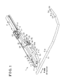
- Fig. 1 is a perspective view of a seat slide apparatus for a vehicle according to a first embodiment disclosed here;
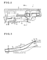
- Fig. 2 is a plane view of the seat slide apparatus for the vehicle according to the first embodiment disclosed here;
- Fig. 3 is a cross-sectional view of the seat slide apparatus for the vehicle taken on line III-III of Fig. 2 ;
- Fig. 4 is a cross-sectional view of the seat slide apparatus for the vehicle taken on line IV-IV of Fig. 3 ;
- Fig. 5 is a lateral cross-sectional view of a seat slide apparatus for a vehicle according to a second embodiment disclosed here;
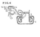
- Fig. 6 is a plane view of a seat slide apparatus for a vehicle according to a third embodiment disclosed here.
- a seat slide apparatus 1 for a vehicle includes a lower rail 3 which is arranged to extend in a front-rear direction of the vehicle and is fixed to a vehicle floor.
- An upper rail 4 is attached to the lower rail 3 to be movable relative to the lower rail 3.
- a single set of the upper rail and the lower rail is shown in the drawings.
- two sets of the upper rail and the lower rail serving as a pair are provided.
- directions such as "width direction”, “upward”, “downward”, “front”, “rear”, or the like, correspond to an orientation of the vehicle.
- the lower rail 3 includes side wall portions 11, 11 which are provided upright at both sides thereof in a width direction and serve as a pair, and a bottom wall portion 12 connecting base ends (i.e., bottom ends) of the side wall portions 11, 11.
- a folded wall portion 13 is provided at a top end of each of the side wall portions 11, 11. The folded wall portion 13 is formed continuously from the top end of the side wall portion 11 to extend inwardly in the width direction and is bent to further extend towards the base end of the side wall portion 11 in a downward direction.
- the upper rail 4 includes side wall portions 14, 14 which extend in an upward-downward direction between the folded wall portions 13, 13 of the lower rail 3 and serve as a pair, and a cover wall portion 15 connecting base ends (i.e., top ends) of the side wall portions 14, 14.
- a folded wall portion 16 is provided at a bottom end of each of the side wall portions 14, 14. The folded wall portion 16 is formed continuously from the bottom end of the side wall portion 14 to extend outwardly in the width direction and is bent to further extend upwardly to be enclosed by the side wall portion 11 and the folded wall portion 13.
- the lower rail 3 and the upper rail 4 are formed in configurations each having a U-shaped cross section and openings of the lower rail 3 and the upper rail 4 face each other. Disassembling of the lower rail 3 and the upper rail 4 from each other in an upward-downward direction is prevented mainly by the engagement of the folded wall portion 13 and the folded wall portions 16.
- the cross sections of rails of the lower rail 3 and the upper rail 4 are rectangularly shaped.
- the lower rail 3 and the upper rail 4 form a space S therebetween.
- a retainer 18 retaining balls 17, 17 which are arranged in parallel to each other in an upward-downward direction is provided between each of the folded wall portions 16 and the side wall portion 11 provided facing the folded wall portion 16.
- the upper rail 4 is supported slidably in a longitudinal direction (a front-rear direction of the vehicle) relative to the lower rail 3 in a manner that the balls 17 rolls between the upper rail 4 and the lower rail 3.
- Plural lock holes 13a are formed on at least one of the folded wall portions 13 of the lower rail 3 to be arranged at predetermined intervals over an approximately entire length of the lower rail 3 in the longitudinal direction thereof (i.e., a direction perpendicular to the drawings).
- a penetration hole 4a is formed on the upper rail 4 at a center portion in the longitudinal direction thereof.
- the penetration hole 4a is formed by cutting out a corner portion of the upper rail 4 formed by a portion of the cover wall portion 15 and a portion of one of the side wall portions 14 (see the side wall portion 14 provided at the left side in Fig. 4 ).
- Plural holes 14a are formed on a bottom portion of the side wall portion 14 at predetermined intervals within a range corresponding to a range of the penetration hole4a in the longitudinal direction.
- plural holes (e.g., the same number with the number of the hole 14a) 16a are formed on the folded wall portion 16 which is formed continuously from the side wall portion 14 at predetermined intervals.
- the plural holes 14a and 16a are arranged at positions where the holes 14a and 16a face each other.
- the plural holes 14a and 16a are configured to face, or to be compatible with lock holes 13a (e.g., the same number with the number of the hole 14a and the hole 16a) which are formed on the lower rail 3 adjacent to one another in a longitudinal direction of the lower rail 3.
- the intervals of the plural holes 14a and 16a correspond to the interval of the lock holes 13a which are arranged adjacent to one another.
- a lock lever 21 made from a plate is rotatably connected to the upper rail 4 via a bracket 23 within a range of the penetration hole 4a in the longitudinal direction.
- the lock lever 21 includes a body portion 21 a which is shaped in a plane plate form and a pair of supporting pieces 21 b which are bent in an upward direction from both ends of the bottom portion of the body portion 21 a in the longitudinal direction of the upper rail 4 (i.e., a direction orthogonal to Fig. 4 ).
- the lock lever 21 is supported by the supporting pieces 21 b, 21 b to be rotatable about a rotational axis O1 which extends in a longitudinal direction of the upper rail 4 outside the space S.
- the lock lever 21 includes plural lock pawls 21 c (e.g., the same number with the number of the hole 14a; the number of the hole 14a is determined to be equal to or greater than the number of the lock pawl 21 c) which are formed at the body portion 21 a and arranged to enter the space S via the penetration hole 4a. Further, the plural lock pawls 21 c are formed so as to fold outwardly from the space S (i.e., left side in Fig. 2 ). The lock pawls are formed at predetermined intervals. The lock pawl 21c is configured to be selectively inserted into and removed from the holes 14a, 16a in response to the rotation of the lock lever 21 about the rotational axis O1.
- the lock lever 21 includes a bent portion 21e which is formed at an end of the body portion 21 a and is curved to slant in a downward direction.
- the lock lever 21 includes a contact portion 21 d at a top surface of the bent portion 21 e (i.e. a curved surface at a border between the body portion 21 a and the bent portion 21 e).
- a torsion wire 22 serving as a first biasing member is provided at a top portion of the upper rail 4.
- a first end of the torsion wire 22 is engaged with the lock lever 21 and a second end of the torsion wire 22 is engaged with the bracket 23.
- the lock lever 21 is constantly biased by the torsion wire 22 in a rotational direction by which the lock pawl 21c is inserted into the holes 13a, 14a, and 16a (i.e., in the clockwise direction in Fig. 4 ), and is elastically retained at a predetermined initial position.
- the seat slide apparatus 1 for the vehicle includes the lower rails 3, the upper rails 4, the lock levers 21, and the torsion wires 22, or the like, which are arranged at both sides in a vehicle seat width direction as a pair.
- a seat serving as a seating portion of an occupant is fixed to the upper rails 4, 4 to be supported.
- the seat is allowed to adjust the position of the upper rails 4, 4 relative to the vehicle floor in the longitudinal direction (i.e., the front-rear direction of the vehicle).
- a support bracket 31 which is made from a plate is fixed to each of the upper rails 4, 4 at one side relative to the lock lever 21 in the longitudinal direction (bottom left side in Fig. 1 ).
- the support bracket 31 includes an attaching wall portion 32 which extends in a width direction of the upper rail 4 to be fastened to the cover wall portion 15, and a first side wall portion 33 which extends downward from an end of the attaching wall portion 32 in a state where the first side wall portion 33 covers the side wall portion 11 which is arranged facing the opposing lower rail 3.
- the support bracket 31 includes a bottom wall portion 34 which extends outwardly from a bottom end of the first side wall portion 33 in a width direction of the lower rail 3, and a second side wall portion 35 which is formed in a triangular shape and extends upwardly from an end of the bottom wall portion 34.
- the support bracket 31 further includes a support wall portion 36 which extends from one side of the first side wall portion 33 (a side shown at bottom left side in Fig. 1 ) outwardly in the width direction of the lower rail 3.
- a rectangular shaped insertion hole 37 which opens in the longitudinal direction of the upper rail 4 is formed on the support wall portion 36.
- a torsion spring 41 serving as a second biasing member is provided at the support bracket 31.
- a first end of the torsion spring 41 is engaged with the first side wall portion 33 and a second end of the torsion spring 41 is engaged with the second side wall portion 35.
- the torsion spring 41 applies a downward biasing force, which has a fulcrum at the first and second end portions of the torsion spring 41, to an extended portion 43 (see Fig. 2 ) formed in a U-shape between the first and the second end portions.
- an operational lever 51 which is formed by bending a pipe member is configured to be connected to each of the support brackets 31 provided at each side of the seat in the width direction.
- the operational lever 51 includes an operational portion 51a which extends in the width direction of the seat and end portions 51 b, 51 b each serving as a lever portion which are bent in the longitudinal direction of the upper rail 4 towards the corresponding lock levers 21, 21 respectively.
- the operational lever 51 integrally includes the end portions 51, 51.
- the operational lever 51 further includes a pressed portion 52, at end portions thereof, which is formed by pressing each of the end portions 51 b, 51 b in an upward-downward direction to have a plate configuration.
- the operational lever 51 further includes a retaining slit 53 which is formed on a top portion of a base end portion of each of the pressed portions 52, 52 in a width direction of the rail.
- the retaining slit 53 extends in a direction which is orthogonal to an inserting direction of the operational lever 51 (i.e., a penetrating direction of the insertion hole 37).
- the end portion 51 b of the operational lever 51 is inserted into the insertion hole 37 of the support wall portion 36 (support bracket 31) along the longitudinal direction of the upper rail 4 so that the operational lever 51 is supported by the support wall portion 36. Further, the operational lever 51 is operationally connected to the lock lever 21 by positioning the pressed portion 52 on the corresponding contact portion 21d of the lock lever 21 (see Fig. 4 ). In those circumstances, the extended portion 43 of the torsion spring 41 is fitted into the retaining slit 53 so that the end portion 51 b of the operational lever 51 is engaged and prevented from being disengaged in a state where a top portion of the end portion 51 b of the operational lever 51 is biased in a downward direction.
- the support wall portion 36 (insertion hole 37) serves as a fulcrum of a rotation of the operational lever 51 at a portion which contacts a top portion of each of the end portions 51 b, 51 b of the operational lever 51 (i.e., hereinafter referred to as the contact portion). Accordingly, the support wall portion 36 supports the operational lever 51 to be rotatable about a rotational axis 02 which is defined at the contact portion of the support wall portion 36 and the operational lever 51 (i.e., the top portion of the end portion 51 b).
- the fulcrum of the rotation of the operational lever 51 is set using the support bracket 31 (support wall portion 36) to set an operational force and an operational amount of the operational lever 51 which is required for unlocking the lock lever 21 by leverage.
- the rotational direction (rotational axis 02) of the operational lever 51 and the rotational direction (rotational axis O1) of the lock lever 21 are different from one another.
- the torsion spring 41 is configured to elastically retain the operational lever 51 at a predetermined initial position so as to maintain a linked state of the operational lever 51 and the lock lever 21.
- a cushioning member 56 formed in a pin shape and made of, for example, rubber or resin is secured to the pressed portion 52 of the operational lever 51.
- the cushioning member 56 includes a semispherical cushioning portion 56a which is configured to elastically contact or to be approximate to the contact portion 21 d of the lock lever 21 which is retained at the predetermined initial position by the torsion wire 22 when the operational lever 51 is retained at the predetermined initial position by the torsion spring 41.
- the lock lever 21 and the operational lever 51 are arranged so that the contact portion 21 d and the pressed portion 52 do not directly contact each other in a state where the cushioning portion 56a is in contact with the contact portion 21 d without the operation of the lock lever 21.
- the contact of the pressed portion 52 with the contact portion 21d is restricted by the cushioning member 56 which is in contact with the contact portion 21 d of the lock lever 21.
- the pressed portion 52 is configured to contact the contact portion 21d of the lock lever 21 at a portion closer to the base end portion relative to the cushioning member 56.
- the cushioning member 56a is gradually separated from the contact portion 21d in accordance with the proceeding of the operation of the lock lever 21. As shown in Fig.
- the sliding contact between the cushioning member 56 and the lock lever 21 is not constant when releasing the restriction of the movement of the lock lever 21, and the deterioration (friction, or the like) of the cushioning member 56 because of the sliding contact therebetween is restrained. Further, because the sliding contact between the cushioning member 56 and the lock lever 21 is canceled when the greater force by the rotation of the operational lever 51 is applied so that the operational force is transmitted by the direct contact between the pressed portion 52 and the lock lever 21, the deterioration of the cushioning member 56 is restrained.
- the lock lever 21 When the operational force of the operational lever 51 (operational portion 51 a) is released, the lock lever 21 is biased by the torsion wire 22 to rotate about the rotational axis O1 in the clockwise direction in Fig. 4 , that is, the lock lever 21 rotates in a direction so that the lock pawl 21c is inserted into the holes 13a, 14a, and 16a (i.e., returning rotation). Accordingly, the relative movement of the lower rail 3 and the upper rail 4 is restricted again.
- the end portions 51 b, 51 b of the operational lever 51 rotate about the rotational axis 02 in the counterclockwise direction in Fig. 3 in cooperation with the lock levers 21, 21.
- the pressed portion 52 of the operational lever 51 includes the restriction portion 52a which is positioned at the inner side in the width direction of the seat so that each of the restriction portions 52a, 52a are arranged to face each other. Accordingly, even when the operational lever 51 is to move in one of the directions in the width direction of the seat relative to the lock lever 21, one of the restriction portions 52a positioned at the side corresponding to the width direction that the operational lever 51 is to move comes to be engaged with the bent portion 21 e of the lock lever so as to restrict the movement. Accordingly, the cancellation of the restricted state of the relative movement of the lower rail 3 and the upper rail 4 by the lock lever 21 by the operation of the operational lever 51 can be performed more stably. Further, because the pressed portion 52 includes the restriction portion 52a, the rigidity of the end of the operational lever 51 is enhanced.
- the cushioning member 56 contacts the lock lever 21 (i.e., contact portion 21d) at the initial stage of the rotational operation of the operational lever 51 to restrict the contact between the operational lever 51 and the pressed portion 52.
- the cushioning member 56 restricts the contact of the pressed portion 52 of the operational lever 51 and the lock lever 21. Accordingly, a generation of a noise such as hitting sound generated between the pressed portion 52 and the lock lever 21 can be restrained.
- the cushioning member 56, the pressed portion 52 of the operational lever 51, and the lock lever 21 are arranged so that the cushioning member 56 is separated from the lock lever 21 and the pressed portion 52 and the lock lever 21 directly contact each other when the higher pressure is applied.
- the cushioning member 56 and the lock lever 21 slidingly contact each other, for example, when canceling the restricted state of the relative movement of the lower rail 3 and the upper rail 4 by the lock lever 21, the deterioration of the cushioning member 56 can be restrained and the reduction of the noise restraining effects when using the seat slide apparatus can be restrained.
- the operational lever 51 by rotating the end portions 51 b, 51 b in response to the operation of the operational portion 51 a, the operational lever 51 simultaneously transmits the operational force to both of the lock levers 21, 21 to cancel the restriction of the relative movement of the lower rail 3 and the upper rail 4. Further, in those circumstances, even if one of the pressed portions 52 of the operational lever 51 is in contact with the lock lever 21, there is a possibility that the other pressed portion 52 is not in contact with the lock lever 21 due to the influence of the variations when assembled.
- the operational lever 51 when the operational lever 51 is about to be displaced in one of the directions in the width direction of the operational lever 51, the displacement of the operational lever 51 in the width direction of the seat is restricted by the engagement of the restriction portion 52a of the end portion 51 b with the lock lever 21. Accordingly, the cancellation of the restricted state of the relative movement of the lower rail 3 and the upper rail 4 by the lock lever 21 in response to the operation of the operational lever 51 can be performed more stably.
- the pressed portion 52 of the operational lever 51 includes the restriction portion 52a, which enhances the rigidity thereof by an increase of the geometrical moment of inertia.
- a second embodiment of the seat slide apparatus for the vehicle will be explained with reference to Fig. 5 as follows.
- a cushioning member 61 provided at the lock lever 21 may serve as the cushioning member.
- the construction of the cushioning member of the second embodiment is different from the construction of the cushioning member of the first embodiment, and other constructions of the seat slide apparatus 1 for the vehicle according to the second embodiment are similar to the first embodiment and thus the explanations are not repeated.
- the cushioning member 61 made of, for example, rubber or resin is formed in a block shape which has a cut out portion 61 a at a bottom portion at one side in the width direction of the seat (i.e., the side which faces the other lock lever 21).
- the cushioning member 61 which is positioned at the bent portion 21e of the lock lever 21 is retained by an end portion of the torsion wire 22 which is engaged with the lock lever 21 in a state where a folded portion of the end portion of the torsion wire 22 which is engaged with the lock lever 21 is hooked at the cut out portion 61 a.
- the cushioning member 61 is configured, at a top surface 61 b thereof, to elastically contact or to be approximate to a bottom end of the restriction portion 52a of the operational lever 51 which is retained at the predetermined initial position by the torsion spring 41 when the lock lever 21 is retained at the predetermined initial position by the torsion wire 22.
- the operational lever 51 and the lock lever 21 are configured so that the pressed portion 52 and the contact portion 21d do not directly contact each other.
- the contact of the pressed portion 52 and the contact portion 21d is restricted by the contact of the restriction portion 52a to the cushioning member 61 at the initial stage of the rotational operation of the operational lever 51.
- FIG. 6 A third embodiment of the seat slide apparatus for the vehicle will be explained with reference to Fig. 6 as follows.
- a cushioning member 65 which is provided at the lock lever 21 with another connecting construction may be applied as the cushioning member. Constructions related to the cushioning member 65 are different from the constructions of the first embodiment, and other constructions of the third embodiment are similar to those of the first embodiment and thus the explanations are not repeated.
- the cushioning member 65 made of rubber or resin includes a cushioning portion 65a which is tightly attached to an external side surface of the bent portion 21 e and an engaging pawl 65b which is integrally formed with the cushioning portion 65a by bending a bottom end of the cushioning portion 65a to enclose a bottom end portion of the bent portion 21e.
- the cushioning member 56, 61, 65 is not necessarily separated from the opposite member (i.e., the lock lever 21 or the pressed portion 52) as long as at least part of the operational force is transmitted between the pressed portion 52 and the lock lever 21 by allowing the contact of the pressed portion 52 with the lock lever 21.
- a leaf spring and a coil spring, or the like may be applied as the biasing members of the lock lever 21 and the operational lever 51.
- the number of the lock pawls 21 c provided at the lock lever 21 may be one or more (at least one).
- the cross sectional configuration of the lower rail 3 is disclosed in the embodiments, and the configurations of the lower rail 3 may be varied.
- the folded wall portion 13 of the lower rail 3 may be folded to extend outwardly in the width direction of the rail.
- the configuration of the cross section of the upper rail 4 in the embodiments is just an example, and the configurations of the upper rail 4 may be varied.
- the folding wall potion 16 of the upper rail 4 may be folded to extend inwardly in the width direction of the rail.
- the configuration of the cross section of the rail of the upper rail 4 is not limited to the U shape, and the configurations of the upper rail 4 may be varied.
- an inverted T-shape may be applied to a cross-sectional configuration of the upper rail 4.
- a moving direction of the seat in response to the movement of the upper rail 4 relative to the lower rail 3 may be varied, for example, in a front-rear direction of the vehicle or in a width direction of the vehicle.
- the rotational direction of the lock lever 21 and the rotational direction of the operational lever 51 are different from one another.
- the seat slide apparatus 1 for the vehicle includes a pair of the lower rails 3, 3 fixed to the vehicle floor, a pair of the upper rails 4, 4 fixed to the seat and movably connected to the lower rails 3, 3, respectively, a pair of the lock levers 21, 21, which are rotatably connected to the corresponding upper rail 4 at the side of the upper rails 4, 4 which face each other in the width direction of the seat and are engaged with the corresponding lower rail 3, for selectively restricting the movement of the upper rail 4 relative to the lower rail 3, a pair of the support brackets 31, 31 fixed to the corresponding upper rail 4 at the side of the upper rails 4, 4, which face each other in the width direction of the seat, and an operational lever 51 which integrally includes the operational portion 51 a extending in the width direction of the seat and a pair of the lever portions (end portions) 51 b, 51 b which are formed at the both ends of the operational portion 51 a to bend in the front-rear direction of the seat, are rotatably connected to the support brackets 31, 31, respectively,
- the seat slide apparatus 1 for the vehicle further includes a pair of the restriction portions 52, 52 which are formed at the opposing sides of the ends of the lever portions (end portions) 51 b, 51 b in the width direction of the seat and engage with the corresponding lock lever 21 for restricting the displacement of the operational lever 51 in the width direction of the seat.
- the restriction portion 52 of the corresponding lever portion (end portion) 51 b is engaged with the lock lever 21 to restrict the displacement of the operational lever 51 in the width direction of the seat. Accordingly, the cancellation of the restricted state of the relative movement of the lower rail 3 and the upper rail 4 by the lock lever 21 in response to the operation of the operational lever 51 is more stably performed.
- the seat slide apparatus 1 for the vehicle which stably restrains the noise generated between the operational lever 51 and the lock lever 21 through time is provided.
Landscapes
- Engineering & Computer Science (AREA)
- Aviation & Aerospace Engineering (AREA)
- Transportation (AREA)
- Mechanical Engineering (AREA)
- Seats For Vehicles (AREA)
Applications Claiming Priority (1)
| Application Number | Priority Date | Filing Date | Title |
|---|---|---|---|
| JP2009082612A JP5347651B2 (ja) | 2009-03-30 | 2009-03-30 | 車両用シートスライド装置 |
Publications (2)
| Publication Number | Publication Date |
|---|---|
| EP2236347A2 true EP2236347A2 (de) | 2010-10-06 |
| EP2236347A3 EP2236347A3 (de) | 2015-04-22 |
Family
ID=42320935
Family Applications (1)
| Application Number | Title | Priority Date | Filing Date |
|---|---|---|---|
| EP20100157176 Withdrawn EP2236347A3 (de) | 2009-03-30 | 2010-03-22 | Sitzschienenvorrichtung für ein Fahrzeug |
Country Status (4)
| Country | Link |
|---|---|
| US (1) | US8052113B2 (de) |
| EP (1) | EP2236347A3 (de) |
| JP (1) | JP5347651B2 (de) |
| CN (1) | CN101850730B (de) |
Families Citing this family (6)
| Publication number | Priority date | Publication date | Assignee | Title |
|---|---|---|---|---|
| WO2009132944A1 (de) * | 2008-04-28 | 2009-11-05 | C. Rob. Hammerstein Gmbh & Co. Kg | Betätigungseinheit eines kraftfahrzeugsitzes |
| JP5347643B2 (ja) * | 2008-10-15 | 2013-11-20 | アイシン精機株式会社 | 車両用シートスライド装置 |
| JP5551548B2 (ja) * | 2010-09-07 | 2014-07-16 | シロキ工業株式会社 | 車両用スライドレール装置 |
| JP5467602B2 (ja) * | 2010-09-15 | 2014-04-09 | アイシン精機株式会社 | 車両用シートスライド装置 |
| KR101925437B1 (ko) | 2017-11-21 | 2018-12-06 | 주식회사 다스 | 자동차 시트레일의 잠금 해제 장치 |
| JP7024414B2 (ja) * | 2018-01-10 | 2022-02-24 | トヨタ紡織株式会社 | スライド装置 |
Citations (3)
| Publication number | Priority date | Publication date | Assignee | Title |
|---|---|---|---|---|
| JP2000038063A (ja) | 1998-07-24 | 2000-02-08 | Delta Kogyo Co Ltd | 操作レバーの接続構造 |
| JP2005041418A (ja) | 2003-07-25 | 2005-02-17 | Toyo Seat Co Ltd | シートスライド装置 |
| JP2008279806A (ja) | 2007-05-08 | 2008-11-20 | Imasen Electric Ind Co Ltd | シートスライド装置 |
Family Cites Families (11)
| Publication number | Priority date | Publication date | Assignee | Title |
|---|---|---|---|---|
| JPH11268563A (ja) * | 1998-03-25 | 1999-10-05 | Oi Seisakusho Co Ltd | シートスライド装置 |
| EP0943484A3 (de) * | 1998-03-17 | 2000-08-16 | Ohi Seisakusho Co., Ltd. | Sitzverstellschiene |
| JP3523812B2 (ja) * | 1999-08-05 | 2004-04-26 | 岐阜車体工業株式会社 | シートトラックスライド装置におけるロック部材の支持構造 |
| JP3446699B2 (ja) * | 1999-12-20 | 2003-09-16 | トヨタ車体株式会社 | シートスライド装置 |
| US6869057B2 (en) * | 2002-12-20 | 2005-03-22 | Fuji Kiko Co., Ltd. | Seat slide device |
| JP4872313B2 (ja) * | 2005-11-04 | 2012-02-08 | アイシン精機株式会社 | 車両用シートスライド装置 |
| CN101421130B (zh) * | 2006-04-14 | 2011-12-28 | 爱信精机株式会社 | 车辆用座椅滑动装置 |
| US8006949B2 (en) * | 2006-08-07 | 2011-08-30 | Aisin Seiki Kabushiki Kaisha | Seat slide device for vehicle |
| JP5034604B2 (ja) * | 2007-03-29 | 2012-09-26 | アイシン精機株式会社 | 車両用シートスライド装置 |
| JP5287128B2 (ja) * | 2008-10-15 | 2013-09-11 | アイシン精機株式会社 | 車両用シートスライド装置 |
| JP5347643B2 (ja) * | 2008-10-15 | 2013-11-20 | アイシン精機株式会社 | 車両用シートスライド装置 |
-
2009
- 2009-03-30 JP JP2009082612A patent/JP5347651B2/ja not_active Expired - Fee Related
-
2010
- 2010-03-18 US US12/726,625 patent/US8052113B2/en not_active Expired - Fee Related
- 2010-03-22 EP EP20100157176 patent/EP2236347A3/de not_active Withdrawn
- 2010-03-25 CN CN2010101419419A patent/CN101850730B/zh not_active Expired - Fee Related
Patent Citations (3)
| Publication number | Priority date | Publication date | Assignee | Title |
|---|---|---|---|---|
| JP2000038063A (ja) | 1998-07-24 | 2000-02-08 | Delta Kogyo Co Ltd | 操作レバーの接続構造 |
| JP2005041418A (ja) | 2003-07-25 | 2005-02-17 | Toyo Seat Co Ltd | シートスライド装置 |
| JP2008279806A (ja) | 2007-05-08 | 2008-11-20 | Imasen Electric Ind Co Ltd | シートスライド装置 |
Also Published As
| Publication number | Publication date |
|---|---|
| US20100243853A1 (en) | 2010-09-30 |
| CN101850730A (zh) | 2010-10-06 |
| US8052113B2 (en) | 2011-11-08 |
| EP2236347A3 (de) | 2015-04-22 |
| JP5347651B2 (ja) | 2013-11-20 |
| CN101850730B (zh) | 2013-05-22 |
| JP2010234854A (ja) | 2010-10-21 |
Similar Documents
| Publication | Publication Date | Title |
|---|---|---|
| EP2236347A2 (de) | Sitzschienenvorrichtung für ein Fahrzeug | |
| JP5621724B2 (ja) | 車両用シートスライド装置 | |
| JP5347643B2 (ja) | 車両用シートスライド装置 | |
| JP5186997B2 (ja) | シートスライド装置 | |
| EP2415629B1 (de) | Sitzverschiebevorrichtung für ein Fahrzeug | |
| US9238422B2 (en) | Vehicle seat sliding apparatus | |
| JP6996970B2 (ja) | 車両用シートスライド装置 | |
| EP2177393B1 (de) | Fahrzeugsitzschiebevorrichtung | |
| JP5998867B2 (ja) | 車両用シートスライド装置 | |
| JP5983295B2 (ja) | 車両用シートスライド装置 | |
| JP5321998B2 (ja) | 自動車用シートのスライドロック機構 | |
| JP4392309B2 (ja) | 車両用シート | |
| KR101518649B1 (ko) | 차량용 시트레일 록킹장치 | |
| JP2018052401A (ja) | シートスライド装置 | |
| JP2019006380A (ja) | ヘッドレスト | |
| JP5428275B2 (ja) | 車両用シートスライド装置 | |
| KR20090109681A (ko) | 차량 시트래치의 유격저감 구조 | |
| JP7754763B2 (ja) | アンカプレート及び車両用シート | |
| JP2006168688A (ja) | 車両用シートスライド装置 | |
| JP7338218B2 (ja) | スライド装置 | |
| JP2019006207A (ja) | ヘッドレスト | |
| KR101593048B1 (ko) | 헤드레스트 수평이동장치 | |
| JP2019006206A (ja) | ヘッドレスト | |
| JP6401973B2 (ja) | シートレール装置 | |
| JP2005074101A (ja) | 自動車用チップアップ・スライド式シート |
Legal Events
| Date | Code | Title | Description |
|---|---|---|---|
| PUAI | Public reference made under article 153(3) epc to a published international application that has entered the european phase |
Free format text: ORIGINAL CODE: 0009012 |
|
| AK | Designated contracting states |
Kind code of ref document: A2 Designated state(s): AT BE BG CH CY CZ DE DK EE ES FI FR GB GR HR HU IE IS IT LI LT LU LV MC MK MT NL NO PL PT RO SE SI SK SM TR |
|
| AX | Request for extension of the european patent |
Extension state: AL BA ME RS |
|
| PUAL | Search report despatched |
Free format text: ORIGINAL CODE: 0009013 |
|
| AK | Designated contracting states |
Kind code of ref document: A3 Designated state(s): AT BE BG CH CY CZ DE DK EE ES FI FR GB GR HR HU IE IS IT LI LT LU LV MC MK MT NL NO PL PT RO SE SI SK SM TR |
|
| AX | Request for extension of the european patent |
Extension state: AL BA ME RS |
|
| RIC1 | Information provided on ipc code assigned before grant |
Ipc: B60N 2/08 20060101AFI20150319BHEP |
|
| STAA | Information on the status of an ep patent application or granted ep patent |
Free format text: STATUS: THE APPLICATION IS DEEMED TO BE WITHDRAWN |
|
| 18D | Application deemed to be withdrawn |
Effective date: 20151023 |