EP2236026B1 - Führungseinrichtung für Angelleine - Google Patents
Führungseinrichtung für Angelleine Download PDFInfo
- Publication number
- EP2236026B1 EP2236026B1 EP10158473A EP10158473A EP2236026B1 EP 2236026 B1 EP2236026 B1 EP 2236026B1 EP 10158473 A EP10158473 A EP 10158473A EP 10158473 A EP10158473 A EP 10158473A EP 2236026 B1 EP2236026 B1 EP 2236026B1
- Authority
- EP
- European Patent Office
- Prior art keywords
- fiber
- frame
- reinforced resin
- layer
- fishline
- Prior art date
- Legal status (The legal status is an assumption and is not a legal conclusion. Google has not performed a legal analysis and makes no representation as to the accuracy of the status listed.)
- Active
Links
- KBEAYHPELRJLSM-FDTUMDBZSA-N C/C=C/C/C=N\C Chemical compound C/C=C/C/C=N\C KBEAYHPELRJLSM-FDTUMDBZSA-N 0.000 description 1
Images









Classifications
-
- A—HUMAN NECESSITIES
- A01—AGRICULTURE; FORESTRY; ANIMAL HUSBANDRY; HUNTING; TRAPPING; FISHING
- A01K—ANIMAL HUSBANDRY; AVICULTURE; APICULTURE; PISCICULTURE; FISHING; REARING OR BREEDING ANIMALS, NOT OTHERWISE PROVIDED FOR; NEW BREEDS OF ANIMALS
- A01K87/00—Fishing rods
- A01K87/04—Fishing-line guides on rods, e.g. tips
-
- B—PERFORMING OPERATIONS; TRANSPORTING
- B29—WORKING OF PLASTICS; WORKING OF SUBSTANCES IN A PLASTIC STATE IN GENERAL
- B29C—SHAPING OR JOINING OF PLASTICS; SHAPING OF MATERIAL IN A PLASTIC STATE, NOT OTHERWISE PROVIDED FOR; AFTER-TREATMENT OF THE SHAPED PRODUCTS, e.g. REPAIRING
- B29C70/00—Shaping composites, i.e. plastics material comprising reinforcements, fillers or preformed parts, e.g. inserts
- B29C70/04—Shaping composites, i.e. plastics material comprising reinforcements, fillers or preformed parts, e.g. inserts comprising reinforcements only, e.g. self-reinforcing plastics
- B29C70/06—Fibrous reinforcements only
-
- B—PERFORMING OPERATIONS; TRANSPORTING
- B32—LAYERED PRODUCTS
- B32B—LAYERED PRODUCTS, i.e. PRODUCTS BUILT-UP OF STRATA OF FLAT OR NON-FLAT, e.g. CELLULAR OR HONEYCOMB, FORM
- B32B5/00—Layered products characterised by the non- homogeneity or physical structure, i.e. comprising a fibrous, filamentary, particulate or foam layer; Layered products characterised by having a layer differing constitutionally or physically in different parts
- B32B5/02—Layered products characterised by the non- homogeneity or physical structure, i.e. comprising a fibrous, filamentary, particulate or foam layer; Layered products characterised by having a layer differing constitutionally or physically in different parts characterised by structural features of a fibrous or filamentary layer
Definitions
- the present invention relates to a fishline guide, which is mounted on a fishing rod to guide a fishline, and specifically, to a fishline guide that is characterized by a frame portion which holds a guide ring through which a fishline passes.
- the above-mentioned fishline guide is configured to have a frame to be mounted on the outer circumferential surface of a fishing rod, and a guide ring which is fixed and attached to the frame and through which a fishline actually passes.
- the frame is integrally formed by press-working a plate material made of metal such as stainless steel or titanium, as described in, for example, JP-A-2006-340661 , and in the frame, a ring holding portion for holding the guide ring through which a fishline passes and a fixing portion for mounting on the outer surface of the fishing rod are integrally formed.
- the guide is manufactured bv placing the guide ring in contact with an outer surface of the rod stock, arranging dies to surround the guide ring and rod stock, and injecting a plastic inside the dies, thereby forming the holder from the plastic.
- the holder may be formed by using prepreg.
- the present invention has been made in view of the above-mentioned problems and has an object to provide a fishline guide which is light in weight and has excellent relative strength, relative rigidity, and bending properties.
- a method of manufacturing a fishline guide according to the present invention comprises:
- the prepreg is thermally hardened in a state that the prepreg is bent, so that a bent portion is formed at the plate member.
- the prepreg is thermal hardened while being bent at at least one portion which is to be formed into a bent portion of the frame.
- the frame includes a fixing portion to be attached to a fishing rod, a fishline passing hole portion and a support leg portion connecting the fixing portion to the hole portion, and the first bent portion is formed at a boundary portion between the fixing portion and the leg portion.
- the second bent portion is formed at the leg portion, a bent angle of the first bent portion is larger than a bent angle of the second bent portion.
- the frame is cut out from the plate-shaped body.
- the frame is molded in such a manner that a portion of the plate member other than a portion corresponding to the frame is removed to leave the portion corresponding to the frame.
- the frame is molded by carrying out a press work, or cutting out the frame by liquid, or a cutting tool.
- the method further comprises performing a surface polishing process on the frame by a barrel processing.
- the frame is molded by using a metallic mold, and the bent portion is thermally hardened by applying a stronger pressure compared to regions in the front and the rear thereof.
- a fishline guide according to the present invention comprises: a frame which includes a plurality of fiber-reinforced resin layers formed by laminating a plurality of fiber-reinforced prepregs in which reinforcing fiber is impregnated with synthetic resin.
- the frame includes a fixing portion to be attached to a fishing rod, a fishline passing hole portion and a support leg portion connecting the fixing portion to the hole portion.
- the plurality of fiber-reinforced resin layers are laminated in a direction substantially perpendicular to a plane of the hole portion.
- At least three of the fiber-reinforced resin layers are laminated.
- the plurality of fiber-reinforced resin layers are laminated so that the fibers of the plurality of fiber-reinforced resin layers extends in at least three different directions.
- the frame is formed such that the amount of reinforcing fibers, which are oriented in an intersection direction having an angle with respect to a longitudinal direction thereof, is larger than the amount of reinforcing fibers which are oriented in the longitudinal direction, where the longitudinal direction is from the fixing portion toward the ring holding portion.
- the frame is formed such that reinforcing fibers are disposed in an axial length direction at a neutral axis area which is an intermediate position in the thickness direction of the frame, reinforcing fibers are disposed in a direction intersecting with the axial length direction at the outer side of the neutral axis area, and a woven fabric layer which is woven by reinforcing fibers is disposed at the outermost layer.
- the frame is formed such that the thickness of a prepreg which is disposed at the outermost layer is thinner than the thickness of a prepreg which is disposed at a neutral axis area which is an intermediate position in the thickness direction of the frame.
- the plurality of fiber-reinforced resin layers includes axial length fibers, which extend in a direction from the fixing portion toward the hole portion, and oblique fibers, which extend obliquely.
- the plurality of fiber-reinforced resin layers include a woven fiber-reinforced resin layer disposed at an outermost layer of the frame.
- the woven fabric layer is formed such that the width of a mesh of main fibers composed of reinforcing fibers is smaller than the width of the support leg portion of the frame.
- the bent portion is formed so as to have a higher ratio of fibers than regions in the front and the rear thereof.
- the bent portion is formed such that the amount of impregnated synthetic resin in an outer layer portion of the inner side of the bent portion is larger than the amount of impregnated synthetic resin in a neutral axis portion in the thickness direction.
- the plurality of fiber-reinforced resin layers includes:
- the plurality of fiber-reinforced resin layers includes:
- the amount of fibers in the first fiber reinforcing resin layer is the same as the amount of fibers in the second fiber reinforcing resin layer.
- the plurality of fiber-reinforced resin layers includes:
- a side surface of the frame is formed in such a manner that the plurality of the fiber-reinforced resin layers appearing on the side surface are made flush with each other.
- a surface shape of the side surface is a convex shape.
- curvature of the front face side and the back face side is smaller than that of the central side.
- the side surface of the frame is formed in a smooth surface shape.
- the front and back faces of the frame are formed by woven fabric-shaped fiber-reinforced prepregs.
- the plurality of fiber-reinforced resin layers includes a fiber-reinforced resin layer having a fiber extending in a longitudinal direction in which the leg portion extends.
- a reinforcement layer is interposed among a plurality of fiber-reinforced resin layers.
- a reinforcement layer is disposed further toward the outer face side than an intermediate position among the plurality of fiber-reinforced resin layers.
- reinforcing fibers constituting the reinforcement layer are disposed to be arranged in one direction.
- the reinforcement layer is formed with a reinforcement piece which is provided at the bent portion.
- the frame is constituted into a flat plate form, and an opening is provided in the fixing portion of the frame.
- the support leg portion is integrally formed with the fixing portion through a bent portion, and the fixing portion is formed so that the amount of reinforcing fibers is smaller than that of the bent portion over more than half of the entire length of the fixing portion, or so that it has a high ratio of reinforcing fibers with low elastic modulus.
- a lamination shaping material which forms the fixing portion is formed with reinforcing fibers which have a smaller elastic modulus than reinforcing fibers in the axial length direction of the fishing rod tube, and the thickness of the fixing portion is formed to be thicker than the thickness of the fishing rod tube.
- a resin layer is disposed on at least the side of the fixing portion which comes into contact with the fishing rod tube, and the fixing portion is fixed to the fishing rod tube through the resin layer.
- the reinforcing fibers of the lamination shaping material are exposed on at least the side of the fixing portion which comes into contact with the fishing rod tube, and the side where the reinforcing fibers are exposed is positioned on and fixed to the fishing rod tube.
- the ring holding portion has reinforcing fibers disposed in the circumferential direction of the ring holding portion.
- the support leg portion has a bent portion, and the thickness of the bent portion is set to be thicker than the thickness of the ring holding portion.
- FIG. 1 is a vertical cross-sectional view of the fishline guide
- Fig. 2 is a view as viewed from the direction of an arrow A of Fig. 1
- Fig. 3 is a view showing a state where the fishline guide is mounted on a fishing rod (fishing rod tube).
- the direction of the arrow A coincides with the axial length direction of the fishing rod when the fishline guide has been mounted on the fishing rod
- Fig. 1 the direction of the arrow A coincides with the axial length direction of the fishing rod when the fishline guide has been mounted on the fishing rod
- Fig. 1 the direction of the arrow A coincides with the axial length direction of the fishing rod when the fishline guide has been mounted on the fishing rod
- Fig. 1 the direction of the arrow A coincides with the axial length direction of the fishing rod when the fishline guide has been mounted on the fishing rod
- FIG 3 is a view as viewed the top end side of a fishing rod from the bottom end side of the fishing rod.
- the fishline guide is mounted in such a manner that a ring holding portion is located on the top end side of the fishing rod and a fixing portion is located on the bottom end side of the fishing rod, and hereinafter, a front side means the top end side of the fishing rod and a rear side means a base end side (the bottom end side of the fishing rod).
- a fishline guide 1 has a frame 3 formed by a fiber-reinforced prepreg (hereinafter referred to as a prepreg) in which reinforcing fibers are impregnated with synthetic resin (a configuration of the prepreg and a detailed manufacturing method of the frame will be described later).
- a prepreg fiber-reinforced prepreg
- synthetic resin synthetic resin
- the frame 3 has a fixing portion 5 which is mounted on the outer surface of a fishing rod (fishing rod tube) 40, a ring holding portion 7 (a fishline passing hole portion), on which a guide ring 6 through which a fishline passes is mounted, and a support leg portion 8 which connects the ring holding portion 7 and the fixing portion 5, and is formed into a plate shape in which a width in the left-right direction is larger than a thickness in the axial direction (the direction of the arrow A of Fig. 1 ; the front-back direction) of the ring holding portion 7.
- the fixing portion 5 is a portion (also referred to as a foot portion) which is fixed to the surface of the fishing rod in a lower end of the frame, and in this embodiment, is fixed by a thread tie, adhesion, or the like in a state where, when the fixing portion has been mounted on the fishing rod, the fixing portion extends in the axial length direction thereof and a contact surface 5a on the back side thereof is positioned on the surface of the fishing rod.
- the fixing portion 5 may also have any of various shapes such as 1-foot shape or 2-foot shape.
- the fixing portion may also be formed into an annular shape and attached to the fishing rod, or may also be constituted as a movable guide which is formed into a tubular shape and disposed on the fishing rod so as to be able to move.
- the ring holding portion 7 is a portion which fixes and supports the guide ring 6 so as to be able to guide the fishline in a state where it is separated from the surface of the fishing rod.
- An opening 7a for fitting and fixing the guide ring 6 is formed in the ring holding portion 7, and the ring holding portion 7 as a whole has an approximately circular outer shape.
- the guide ring 6 which is fitted into the opening 7a is configured into a ring shape and formed of a material, which has a small sliding resistance at a fishline guide surface portion 6a which is the inner circumferential surface thereof, such as titanium, aluminum, SUS, ceramics, or the like.
- the support leg portion 8 is a portion which connects the fixing portion 5 and the ring holding portion 7 so as to separate the guide ring 6 from the surface of the fishing rod. Since the support leg portion 8 can be designed into various lengths in accordance with the kind of guide, it also includes a version which slightly protrudes from the ring holding portion 7.
- At least one or more bent portion is formed in the frame 3.
- a first bent portion 10a is formed at a boundary portion between the fixing portion 5 and the support leg portion 8, and a second bent portion 10b, which has a gentler bent than the first bent portion, is formed on the ring holding portion 7 side of the support leg portion 8.
- the boundary portion corresponds to a region which rises from an end portion of the fixing portion 5, which actually is in a fixed state with respect to the outer surface of the fishing rod, toward the ring holding portion 7.
- bent portions as described above are formed at the frame 3, in particular, by forming the second bent portion 10b at the support leg portion 8, it becomes possible to set in a stepwise fashion a bending angle by the bending of the frame as a whole, so that it is possible to disperse stress concentration, thereby improving strength.
- a bending angle of a bent portion (in the drawings, the second bent portion 10b corresponds to this) which is formed at the support leg portion 8 to be smaller than that of a bent portion (in the drawings, the first bent portion 10a corresponds to this) which is formed at the boundary portion between the fixing portion 5 and the support leg portion 8 or in the vicinity thereof.
- a bending angle 61 of the bent portion which is formed at the boundary portion between the fixing portion 5 and the support leg portion 8 or in the vicinity thereof is in the range of 30 degrees to 90 degrees
- set a bending angle ⁇ 2 of the bent portion which is formed at the support leg portion 8 is a smaller angle ( ⁇ 1> ⁇ 2) than the bending angle ⁇ 1 and in the range of 0 degree to 45 degrees
- set a total of both angles to be 30 degrees or more and 100 degrees or less.
- the bending angle is defined by a crossing angle of tangent lines in the front and the rear of the bent portion.
- a bending angle (a crossing angle of a tangent line of a lower surface of the fixing portion 5 and the ring holding portion 7) ⁇ 3 between the fixing portion 5 and the ring holding portion 7, it is preferable that it is set to be in the range of 30 degrees to 100 degrees.
- a portion between two bent portions 10a and 10b is formed into a straight line shape.
- the portion between two bent portions 10a and 10b may also be formed into a curved surface shape having a given curved surface, or the support leg portion may also be configured to have a curved surface as a whole.
- bent portions By forming the bent portions so as to have such an angular relationship, stress concentration on a specific bent portion can be prevented, so that stabilization of strength can be achieved.
- bent portions 10a and 10b which are formed at the frame as described above are regions where breakage or the like easily occurs due to stress concentration.
- improvement in relative strength and relative rigidity can be achieved.
- the frame 3 is formed by press working or the like from a prepreg (it is a plate-shaped body after thermal molding) which is in a state where the bent portions having configurations as described above are formed in advance, as described later. However, at this time, it is formed so as to have a given outer shape.
- the support leg portion 8 which rises from an end portion of the fixing portion 5 through the first bent portion 10a has a width which gradually widens heading up the support leg portion 8, and is integrally connected to the ring holding portion 7 of an approximately circular shape, in which there is formed the opening 7a into which the guide ring 6 is fitted.
- an opening (cutout) 8a may also be formed in the support leg portion 8.
- the frame 3 is formed from the prepreg in which reinforcing fibers are impregnated with synthetic resin.
- the prepreg is constituted in a state where reinforcing fibers such as carbon fibers or glass fibers are arranged in a given direction, or into a woven sheet form, and has a configuration in which thermosetting resin (for example, epoxy resin) or thermoplastic resin (for example, nylon) is impregnated as matrix resin.
- the sheet-shaped prepreg as described above is cut into a given shape, and the cut prepregs are stacked so as to become plural layers.
- the number of sheets (the number of layers) of prepregs which are stacked, or a configuration of individual prepreg is not particularly limited.
- the kind of prepreg or a stacking condition is arbitrarily adjusted.
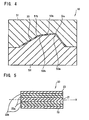
- the prepreg which is laminated in this manner is set in a metallic mold 50 as shown in Fig. 4 .
- the metallic mold 50 of this embodiment is constituted by an upper mold 51 and a lower mold 52, which are parted above and below, and the laminated prepreg (denoted by reference numeral 20) is set at a given position of the lower mold 52. Between the upper mold 51 and the lower mold 52, a cavity portion 50a is formed corresponding to a position where the laminated prepreg 20 is set, and a mold release agent is coated on a surface region thereof.
- the upper mold 51 constituting the metallic mold 50 is configured into a concave shape
- the lower mold 52 is configured into a convex shape
- the cavity portion (this cavity portion corresponds to the thickness of the frame 3) 50a is formed between the upper mold and the lower mold such that when the upper mold and the lower mold are pressed, the frame 3 is formed.
- bent portion forming convex portions 52a and 52b are formed at positions which correspond to the above-described bent portions 10a and 10b when the prepreg 20 laminated into the sheet form is positioned
- bent portion forming concave portions 51a and 51b are formed corresponding to the bent portion forming convex portions 52a and 52b.
- the prepreg 20 is set on the lower mold in a state where the whole of the prepreg 20 is superposed at the same time, or it may also be laminated plural times, such as it being set one by one. By laminating it plural times in this manner, movement of the reinforcing fibers is reduced, so that the prepreg can be set at a given position on the lower mold 52 with high precision.
- the prepreg 20 is positioned on the lower mold 52 and maintained in a given shape in accordance with the shape of the metallic mold.
- the metallic mold only one example is shown, and with respect to a mold parting direction, it is possible to adopt arbitrary aspects such as a left-right direction or an inclined direction.
- the positioned prepreg 20 is pressed and fixed. With respect to the pressing and fixing, it may also be clamped by the upper mold 51 or pressed by hand or a pressing tool.
- a shape corresponding to a frame shape after the molding, which includes bent portions is maintained, and this allows the occurrence of an internal residual stress after the molding to be prevented, so that an improvement in strength and stabilization of strength can be achieved (in this step, the prepreg is in an uncured state (including a state after provisional cure) and the bent portions are formed prior to thermal hardening).
- a heating process is carried out, and after the matrix resin is hardened and molded, a molded article (it is a plate-shaped body 30 having bent portions) is taken out from the metallic mold 50.
- the bent portions when the bent portions are thermally hardened by pressing by the metallic mold 50, it is preferable that the bent portions be pressed relatively more strongly than regions in the front and the rear thereof. In this manner, by strongly pressing the regions of the bent portions, voids in the bent portions (10a and 10b) of the molded frame can be prevented, so that an improvement in strength and stabilization of strength can be achieved. According to this, the bent portions 10a and 10b of the molded frame 3 can have a higher ratio of fibers than those in the regions (the fixing portion or the support leg portion) in the front and the rear thereof, so that it becomes possible to reinforce the bent portions where breakage or the like easily occurs.
- the frame is cut out into a given shape from the plate-shaped body 30 having a plurality of fiber-reinforced resin layers formed by stacking a plurality of prepregs in the thickness direction.
- the prepreg is a plate-shaped body in which the bent portions are formed after the thermal hardening treatment
- an arbitrary method such as cutting by press working, cutting by liquid (water jet or the like), or cutting by a cutting tool (an end mill or the like)
- the cutting-out of the frame may also be carried out by leaving the frame 3 by destroying or removing the unnecessary portions other than the frame 3 of the plate-shaped body.
- a basic outer shape of the frame 3 that is, the ring holding portion 7 having the opening 7a, the support leg portion 8 having the opening 8a, and the like.
- these may also be formed in separate processes.
- the plate-shaped body 30 it is not limited to a shape of one sheet of simple plane, but the thickness of the lamination may also be varied according to positions, a plate-shaped portion may also have a shape (a T shape, an inverted-Y shape, or the like) extending in plural directions or include a curved surface shape, or a plurality of plate-shaped portions may also be combined.
- the detailed processing corresponds to, for example, a processing for forming a shape of the fixing portion 5 into a curved surface shape so as to make the fixing portion be easily positioned on the fishing rod, or performing polishing or the like of an end portion of the fixing portion for easy thread winding or thread tie.
- a surface treatment of the frame having a plurality of fiber-reinforced resin layers formed by stacking a plurality of prepregs in the thickness direction thereof is carried out.
- burrs on the surface are removed by performing barrel processing, and also finishing polishing (polishing) is carried out to the extent that gloss on the surface is obtained.
- polishing polishing
- By performing barrel processing it becomes possible to polish the frame without cutting the reinforcing fibers, so that stabilization of strength can be achieved, and also a fishline guide having an excellent appearance can be obtained.
- a coating film is formed on the whole or a portion of the frame.
- it also is possible to perform painting for an improvement in an appearance or protection of a main body of the frame, vapor deposition of metal or ceramics, or the like.
- the guide ring 6 is mounted on a portion of the opening 7a of the frame formed as described above.
- any fixing method such as fitting, adhesion, or curling.
- the frame 3 of this embodiment is composed of a plurality of fiber-reinforced resin layers in which the prepregs in which reinforcing fibers are impregnated with synthetic resin are laminated.
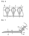
- the plurality of fiber-reinforced resin layers are laminated in the thickness direction (a direction approximately perpendicular to a face of the ring holding portion) of the frame 3. In this embodiment, as shown in Fig.
- the layers include an axial length direction fiber resin layer 21 in which reinforcing fibers are arranged along an axial length direction of the fishing rod, oblique fiber resin layers 22a and 22b in which reinforcing fibers are arranged in a crossing direction having a given angle with respect to the axial length direction of the fishing rod, and woven fabric layers 23 in which reinforcing fibers are woven.
- the axial length direction fiber resin layer 21 is disposed by a prepreg in which reinforcing fibers are arranged in the axial length direction, at a neutral axis area (in Fig. 5 , a neutral axis is denoted by X) which is an intermediate position in the thickness of the frame, the oblique fiber resin layers 22a and 22b are disposed by prepregs in which reinforcing fibers are arranged at a given angle (the angle of inclination is arbitrary.
- the range of 15 degrees to 75 degrees is preferable, and more preferably, an angle in the range of 30 degrees to 60 degrees) with respect to the axial length direction, at the outer sides (both sides) of the axial length direction fiber resin layer, and the woven fabric layers 23 are disposed by prepregs in which reinforcing fibers are woven, at the outermost layers (they are the entire faces of both sides. However, they may also be regions which partly become the outermost region).
- the axial length direction fiber resin layer 21 may also be constituted into plural layers (one layer to four layers). With respect to the oblique fiber resin layers 22a and 22b, the orientation directions of the reinforcing fibers in the respective layers may also be different from each other.
- the fishline guide made of fiber-reinforced resin it is preferable to choose and laminate such prepregs in a state where the reinforcing fibers are oriented in at least three directions when viewing the frame itself from the direction of the arrow A, or in a plan view. That is, by setting the orientation directions of the reinforcing fibers to be three or more directions, it becomes possible to efficiently form a fishline guide which is light in weight and excellent in strength, and also, even if a width of the frame is made small, excellent strength can be obtained.
- the frame 3 is made by disposing reinforcing fibers in the axial length direction at the neutral axis area, disposing reinforcing fibers at the outer sides of the neutral axis area in the direction intersecting the axial length direction, and disposing the woven fabric layers 23 in which reinforcing fibers are woven, at the outermost layers, so that the fishline guide 1, in which an improvement in strength and stabilization of strength are achieved without occurrence of cutting, breakage, or the like even with large flexure, can be realized, and also a reduction in weight can be efficiently achieved.
- the frame 3 be made by making the amount of reinforcing fibers (the reinforcing fibers of the oblique fiber resin layers 22a and 22b), which are oriented in a crossing direction having an angle with respect to a longitudinal direction from the fixing portion 5 toward the ring holding portion 7, be larger than the amount of reinforcing fibers (the reinforcing fibers of the length direction fiber resin layer 21) which are oriented in the longitudinal direction. According to this, it is possible to obtain a fishline guide in which even if the fishline guide 1 is greatly bent so that the frame 3 is bent due to a large load in the direction of an arrow of Fig. 1 , breakage hardly occurs.
- the frame 3 is made such that the thicknesses of the prepregs (the woven fabric layers 23) which are disposed at the outermost layers are thinner than the thickness of the prepreg (the length direction fiber layer 21) which is disposed at the neutral axis area. If doing so, relative strength is improved, peeling of the reinforcing fibers from the end portion can be prevented, and large bending becomes possible.
- the woven fabric layers 23 are at the outermost layers of the frame 3.
- the surfaces of the frame 3 are portions where it is easy for other objects to touch, so that peeling or the like easily occurs, and that there is a possibility that the frame is bent due to tension of the fishline at the time of the actual fishing, so that the reinforcing fibers are peeled from the end portion of the frame or broken, by disposing the woven fabric layers in which reinforcing fibers are woven at these surface regions, crack or peeling of the reinforcing fibers can be effectively prevented and an improvement in strength and stabilization of strength can be achieved.
- the woven fabric layer 23 As shown in Fig. 8 , it is preferable to use a woven fabric layer in which the width w of a mesh of main fibers composed of reinforcing fibers (usually, since a plurality of reinforcing fibers are bundled, thereby constituting a fiber bundle, and the fiber bundles are woven into a fabric form, the mesh is specified by the width of the fiber bundle) is smaller than the width W (here, the width corresponds to the width of the smallest width portion of the support leg portion) of the support leg portion 8 of the frame 3.
- a direction of the mesh of the woven fabric is along an axial length direction AX.
- the entire layer may also be constituted by the woven fabric layer as described above.
- the axial length direction fiber resin layer 21 is disposed at an intermediate layer region of the frame 3. Therefore, even if a bending force acts on the frame 3 along the axial length direction due to tension or the like of the fishline, it becomes possible to efficiently increase the relative rigidity in the direction while achieving a reduction in weight.
- the frame 3 which is formed in this manner is not limited to a plane shape with the same thickness, but the thickness thereof, the amount or elastic modulus in tension of the reinforcing fibers may be changed or adjusted in accordance with portions.
- the adjustment of the thickness, the amount or the elastic modulus in tension of reinforcing fibers can be performed by variously changing the thickness of a lamination or fiber-reinforced prepregs to be laminated, when forming the plate-shaped body 30.
- the bent portion 10a on the fixing portion 5 side is formed such that a radius of an inner curved surface 110A which forms a smaller angle than 180 degrees between the support leg portion 8 and the fixing portion 5 is larger than a radius of an outer curved surface 110B which forms a larger angle than 180 degrees and the thickness T of the bent portion 10a is thicker than the thickness T1 at an intermediate position in the length direction of the fixing portion.
- the thickness T of the bent portion 10a is formed to be thicker than the thickness T2 of the support leg portion 8.
- the inner curved surface 110A is curved more gently than the outer curved surface 110B, and the thickness of this portion is increased, so that relative strength of the bent portion 10a can be improved more than the support leg portion 8 and the fixing portion 5 in the frame 3 and it becomes possible to effectively prevent breakage at the bent portion. Accordingly, the whole of the frame 3 is thinned, and strength and durability of the whole of the fishline guide 1 can be improved. Strength, stabilization, and bending balance of the fishing rod, to which the fishline guide 1 is attached, can be improved.
- the impregnation amount of synthetic resin of an outer layer portion (the curved surface 110A side) of the inside of the bent portion be larger than the impregnation amount of synthetic resin of a neutral axis portion in the thickness direction.
- the fishline guide which is formed according to the manufacturing method as described above, compared to a fishline guide made of metal, a configuration can be obtained in which weight is light and also relative strength, relative rigidity, and bending properties are excellent. For this reason, even if such as fishline guide is mounted in a plurality of pieces, the entire weight of the fishing rod is not increased, and performance of the fishing rod is improved. In particular, at a portion such as a tip rod, a further reduction in weight can be achieved, so that a delicate touch is easily sensed, whereby further improvement in performance of the fishing rod can be achieved.
- the present invention has features that the frame portion constituting the fishline guide is constituted by the fiber-reinforced prepreg and also the arrangement aspect of the prepreg as described above is used such that relative strength, relative rigidity, and the like are increased and breakage or the like does not occur in particular at a region of the bent portion.
- the kind or the elastic modulus of the reinforcing fibers, the impregnation amount of resin, a configuration such as a thickness, a laminated state, and the like can be modified in various ways without being limited to the embodiment.
- Fig. 9 is a view when viewing the frame 3 from the front side (the top end side of the fishing rod).
- the frame 3 is constituted by a laminated material 20 having a plurality of fiber-reinforced resin layers in which the prepregs in which reinforcing fibers are impregnated with synthetic resin are laminated in the front-rear direction of the frame, and in this embodiment, a total of 8 layers of prepregs are used.
- the layers of the laminated material 20 are defined as a first layer 20a, a second layer 20b, a third layer 20c, a fourth layer 20d, a fifth layer 20e, a sixth layer 20f, a seventh layer 20g, and an eighth layer 20h in order heading from the front side (the top end side of the fishing rod) to the rear side (the bottom end side of the fishing rod) (in this laminated structure, an interface between the fourth layer 20d and the fifth layer 20e, which corresponds to the center of the lamination side, corresponds to the center C of the laminated material 20).
- the vertical direction when viewing the fishline guide from the front is defined as a length axis X of the frame, and a direction of the fibers in each layer is shown by an oblique line or a grid line.
- Front and back faces (the first layer 20a and the eighth layer 20h) which correspond to the outermost layers of the laminated material 20 are constituted by fiber-reinforced resin layers which are woven fabrics.
- reinforcing fibers constituting the woven fabric be set to be disposed in a direction along the length axis X and a direction (horizontal direction) intersecting with this, as shown in Fig. 9 .
- the inner layer sides (the second layer 20b and the seventh layer 20g) of the first layer 20a and the eighth layer 20h are constituted by axial fiber-reinforced resin layers which are composed of the reinforcing fibers arranged in one direction which is a direction along the length axis X (it need not exactly coincide with the length axis).
- the inner layer sides (the third layer 20c and the sixth layer 20f) thereof are constituted by oblique fiber-reinforced resin layers in which reinforcing fibers are inclined rightward (defined as +) with respect to the length axis X when viewing from the front.
- the angle of inclination with respect to the length axis X be in the range of 10° to 60°, and the angles of inclination of the reinforcing fibers of both layers need not exactly coincide with each other.
- the inner layer sides (the fourth layer 20d and the fifth layer 20e) thereof are constituted by oblique fiber-reinforced resin layers in which reinforcing fibers are inclined leftward (defined as -) with respect to the length axis X when viewing from the front.
- the angle of inclination with respect to the length axis X be in the range of -10° to -60°, and the angles of inclination of the reinforcing fibers of both layers need not exactly coincide with each other.
- the layers in the front and the rear of the center C in the thickness direction of the laminated material 20 are all made of the oblique fiber-reinforced resin layers (the fourth layer 20d and the fifth layer 20e) in which reinforcing fibers are inclined leftward, and the outer sides thereof are all made of the oblique fiber-reinforced resin layers (the third layer 20c and the sixth layer 20f in which reinforcing fibers are inclined rightward.
- a state is made where at one side and the other side with respect to the center C of the laminated material 20, the oblique fiber-reinforced resin layers in which reinforcing fibers are inclined in the same direction as each other with respect to the length axis X of the frame are disposed (the fourth layer 20d and the fifth layer 20e; and the third layer 20c and the sixth layer 20f).
- the configuration of the laminated material 20 as described above a reduction in weight of the frame itself can be achieved, and also it becomes possible to construct a fishline guide which is excellent in relative strength, relative rigidity, and bending properties.
- the oblique fiber-reinforced resin layers in which reinforcing fibers are inclined in the opposite directions to each other with respect to the length axis X of the frame are disposed at one side and the other side with respect to the center C of the laminated material 20, when casting or a fish is caught or in other cases, even if backward and forward bending or torsion of the frame 3 of the fishline guide due to a load applied thereto occurs, a bending direction is not biased, so that breakage or the like can be effectively suppressed. Since there is hardly any concentration of places where the fishline touches the guide ring due to bending of the frame 3, abrasion of the fishline can be prevented.
- the laminated material 20 having the above-described configuration has the axial fiber-reinforced resin layers (the second layer 20b and the seventh layer 20g) which are composed of the reinforcing fibers arranged in one direction which is a direction along the length axis x, flexural rigidity in a longitudinal axial direction can be increased in this manner.
- the laminated material 20 having the above-described configuration has the fiber-reinforced resin layers which are woven fabrics at the front and back faces (the first layer 20a and the eighth layer 20h) which correspond to the outermost layers, even if the fishline comes into contact with it, cracking, peeling, or the like of the reinforcing fibers hardly occurs, so that an improvement in strength and stabilization of strength can be achieved and also the inner fiber-reinforced resin layers can be effectively protected.
- a fiber-reinforced resin layer in which the width w of the mesh of main fibers composed of reinforcing fibers (usually, since a plurality of reinforcing fibers are bundled, thereby constituting a fiber bundle and the fiber bundles are woven into a woven fabric form, the mesh is specified by the width of the fiber bundle) is smaller than the width W (here, the width corresponds to the width of the smallest width portion of the support leg portion) of the support leg portion 8 of the frame 3.
- the reinforcing fibers can be oriented in a direction along the extending direction of the support leg portion 8 which is constituted as described above and a direction intersecting at right angles with it, so that breakage or peeling of the reinforcing fibers can be effectively prevented.
- the oblique fiber-reinforced resin layers (the fourth layer 20d and the sixth layer 20f; and the third layer 20c and the fifth layer 20e) which are respectively provided at one side and the other side in the front and the rear of the center C and in which reinforcing fibers are inclined in the opposite directions to each other, it is preferable to use the prepregs in which the amounts of fibers are the same as each other.
- a pair of left and right support leg portions 8 is formed of the same laminated material 20 formed by laminating the same prepregs in the same laminating order, so that rigidity or the like is balanced.
- Fig. 11 is a view showing a second embodiment of the frame portion and an enlarged view showing a laminated structure of the prepreg constituting the frame.
- a laminated material 22 of this embodiment a total of four layers of prepregs are used.
- the layers of the laminated material 22 are defined as a first layer 22a, a second layer 22b, a third layer 22c, and a fourth layer 22d in order heading from the front side (the top end side of the fishing rod) to the rear side (the bottom end side of the fishing rod) (in this laminated structure, an interface between the second layer 22b and the third layer 22c corresponds to the center C of the laminated material 22 in the laminating order).
- Front and back faces (the first layer 22a and the fourth layer 22d) which correspond to the outermost layers of the laminated material 22 are constituted by fiber-reinforced resin layers which are woven fabrics.
- the inner layer side (the second layer 22b) of the first layer 22a is constituted by an oblique fiber-reinforced resin layer in which reinforcing fibers are inclined rightward
- the inner layer side (the third layer 22c) of the fourth layer 22d is constituted by an oblique fiber-reinforced resin layer in which reinforcing fibers are inclined leftward. That is, a state is made where at one side and the other side with respect to the center C of the laminated material 22, the oblique fiber-reinforced resin layers in which reinforcing fibers are inclined in the opposite directions to each other with respect to the length axis X of the frame are disposed.
- the frame having this configuration similarly to the above-described embodiment, even if backward and forward bending or torsion of the frame 3 of the fishline guide due to a load applied thereto occurs, a bending direction is not biased, so that breakage or the like can be effectively suppressed. Since there is hardly any concentration of places where the fishline touches the guide ring due to the bending of the frame 3, abrasion of the fishline can be prevented. Further, in this embodiment, due to a reduction in the number of layers, a reduction in weight can be achieved, so that a configuration suitable for a fishline guide on the top end side of the fishing rod of the fishing rod is obtained.
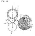
- Fig. 12 is a view showing a third embodiment of the frame portion and an enlarged view showing a lamination structure of the prepregs constituting the frame.
- a total of nine layers of prepregs are used.
- the layers of the laminated material 24 are defined as a first layer 24a, a second layer 24b, a third layer 24c, a fourth layer 24d, a fifth layer 24e, a sixth layer 24f, a seventh layer 24g, an eighth layer 24h, and a ninth layer 24i in order heading from the front side (the top end side of the fishing rod) to the rear side (the bottom end side of the fishing rod).
- the fifth layer 24e constitutes a core layer which corresponds to the center C in the laminating order.
- Front and back faces (the first layer 24a and the ninth layer 24i) which correspond to the outermost layers of the laminated material 24 are constituted by fiber-reinforced resin layers which are woven fabrics, and the inner layer sides (the second layer 24b and the eighth layer 24h) thereof are constituted by axial fiber-reinforced resin layers which are composed of the reinforcing fibers arranged in one direction which is a direction along the length axis x.
- the inner layer sides (the third layer 24c and the seventh layer 24g) thereof are respectively constituted by an oblique fiber-reinforced resin layer in which reinforcing fibers are inclined rightward with respect to the length axis X and an oblique fiber-reinforced resin layer in which reinforcing fibers are inclined leftward with respect to the length axis
- the inner layer sides (the fourth layer 24d and the sixth layer 24f) thereof are respectively constituted by an oblique fiber-reinforced resin layer in which reinforcing fibers are inclined leftward with respect to the length axis X and an oblique fiber-reinforced resin layer in which reinforcing fibers are inclined rightward with respect to the length axis.
- the core layer 24e which corresponds to the center C is constituted by an axial fiber-reinforced resin layer which is composed of the reinforcing fibers arranged in one direction which is a direction along the length axis X.
- the layers in the front and the rear of the center C (the core layer 24e) of the laminated material 24 are in states where the oblique fiber-reinforced resin layers in which reinforcing fibers are inclined in the opposite directions to each other with respect to the length axis X of the frame are disposed (the fourth layer 24d and the sixth layer 24f), and the layers on the outer sides thereof are also in states where the oblique fiber-reinforced resin layers in which reinforcing fibers are inclined in the opposite directions to each other are disposed (the third layer 24c and the seventh layer 24g).
- the laminated material 24 is in a state where the fiber-reinforced resin layers on both sides with respect to the center C (the core layer 24e) are laminated such that the directions of the fibers become directions symmetrical to each other toward the outer layers.
- the core layer 24e which is the axial fiber-reinforced resin layer is disposed at the center, even if a bending force acts on the frame 3 along the axial length direction due to tension or the like of the fishline, relative rigidity in the direction can be efficiently increased while a reduction in weight can also be achieved.
- Fig. 13 is a view showing a fourth embodiment of the frame portion and an enlarged view showing a lamination structure of the prepregs constituting the frame.
- a support leg portion 8A which connects the fixing portion 5 and the ring holding portion 7 is formed into a form of one piece of plate without forming a central window portion (the opening 8a) as in the above-described embodiments.
- a shape of the support leg portion 8A can be suitably modified in accordance with, for example, the kind of fishing rod, a stem of the fishing rod, on which the fishline guide is mounted, or the like, and also with respect to the support leg portion formed into a form of the plate as shown in the drawing, it is possible to suitably modify it, for example, by folding an intermediate portion or performing chamfering.
- a total of ten layers of prepregs are used, and similarly to the above-described embodiment, the layers of the laminated material 26 are defined as a first layer 26a, a second layer 26b, a third layer 26c, a fourth layer 26d, a fifth layer 26e, a sixth layer 26f, a seventh layer 26g, an eighth layer 26h, a ninth layer 26i, and a tenth layer 26j in order heading from the front side (the top end side of the fishing rod) to the rear side (the bottom end side of the fishing rod) (in the number of laminated layers, which is such an even number, an interface between the fifth layer 26e and the sixth layer 26f corresponds to the center C of the laminated material 26).
- Front and rear faces (the first layer 26a and the tenth layer 26j) which correspond to the outermost layers of the laminated material 26 are constituted by fiber-reinforced resin layers which are woven fabrics, and the inner layer sides (the second layer 26b and the ninth layer 26i) thereof are constituted by axial fiber-reinforced resin layers which are composed of the reinforcing fibers arranged in one direction which is a direction along the length axis X.
- the inner layer sides (the third layer 26c and the eighth layer 26h) thereof are all constituted by oblique fiber-reinforced resin layers in which reinforcing fibers are inclined rightward with respect to the length axis X
- the inner layer sides (the fourth layer 26d and the seventh layer 26g) thereof are respectively constituted by an oblique fiber-reinforced resin layer in which reinforcing fibers are inclined rightward with respect to the length axis X and an oblique fiber-reinforced resin layer in which reinforcing fibers are inclined leftward with respect to the length axis.
- the layers (the fifth layer 26e and the sixth layer 26f) on both sides with respect to the center C of the laminated material 26 are in states where the oblique fiber-reinforced resin layers in which reinforcing fibers are inclined in the opposite directions (in the fifth layer 26e, the left direction, and in the sixth layer 26f, the right direction) to each other with respect to the length axis X are disposed.
- the layers in the front and the rear of the center C of the laminated material 26 are in states where the oblique fiber-reinforced resin layers in which reinforcing fibers are inclined in the opposite directions to each other with respect to the length axis X of the frame are disposed (the fifth layer 26e and the sixth layer 26f), and the layers on the outer sides thereof are also in states where the oblique fiber-reinforced resin layers in which reinforcing fibers are inclined in the opposite directions to each other are disposed (the fourth layer 26d and the seventh layer 26g).
- the fiber-reinforced resin layers on both sides with respect to the center C are in states where they are laminated such that the directions of the fibers become directions symmetrical to each other toward the outer layers, when a force twisting the frame acts on it, it becomes possible to achieve an improvement in relative strength even with respect to torsion in either the left or the right direction.
- Fig. 14 is an enlarged view showing a laminated structure of the prepreg constituting the frame
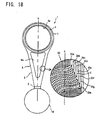
- Fig. 15 is a cross-sectional view taken along line A-A of Fig. 14 .
- configurations constituted in the same manner as those of the fishline guides in the above-described embodiments are denoted by the same reference numerals, and the detailed explanation thereof is omitted.
- FIG. 14 is a view when viewing the frame 3 from the front side (the top end side of the fishing rod).
- a laminated structure of the prepreg of Fig. 14 is the same as the laminated structure of the prepreg shown Fig. 9 of the first embodiment, the explanation thereof is omitted.
- a direction X in which the frame 3 (the support leg portion 8) extends is defined as the length axis X of the frame, and the direction of the fibers in each layer is shown by an oblique line or a grid line.
- the side surface of the frame can come into contact with the fishline, it is preferable to perform a treatment so as to prevent damage to the fishline and also prevent the surface itself from being damaged.
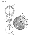
- the reinforcing fibers are configured to have an approximately circular cross-section shape, if cutting-out is performed as shown in Fig. 6 , there are many cases where at an exposed portion (an exposed end surface of the fibers) in the side surface, the reinforcing fibers are cut obliquely to the length axis X. Therefore, a state is made where a number of fibers having an end surface of an oval shape are disposed at the surface of the side surface, and such exposed end surfaces of the fibers appear, so that a surface state is obtained which is hardly damaged.
- a polishing treatment is performed such that in this exposed state (a state of the side surface), a plurality of laminated layers is made flush with each other and a surface shape in the side surface becomes a convex surface shape, and consequently, interlayer peeling, damage to the fishline, or the like is more effectively prevented.
- an interlayer in the prepreg which is exposed at the side surface becomes often microscopically slightly concave.
- the matrix resin synthetic resin
- the above-mentioned polishing treatment can be realized, for example, by carrying out barrel polishing to remove burrs on the surface and carrying out finishing polishing to the extent that gloss of the surface can be obtained.
- the cross-section of the frame is understood as a rectangular shape R
- the surface shapes of surfaces 25 and 25 of both sides S1 and S2 of the laminated material 20 (frame) are convex surface shapes which protrude outward, and the convex surface is continuously formed in a longitudinal direction along the side surface of the frame.
- a finishing treatment is performed to form a smooth surface shape such that the reinforcing fibers and the matrix resin are made flush with each other (the end portions of the reinforcing fibers often slightly protrude, but are formed so as to be made approximately flush with each other).
- the surfaces 25 and 25 in the side surfaces are polished such that a mean surface roughness (Ra value) is 10 ⁇ m or less.
- corner portions 25A which transition from the front face 26a and the back face 26b to the side surface may also be chamfered
- the whole of a side surface portion 25B may also be made into a planar shape (a portion may also be made into a planar shape), or the regions which transition from the side surface portion 25B of a planar shape to the front face 26a and the back face 26b may also be finished into a curved surface shape without chamfering.
- each side surface is made into a mountain shape in the front-rear direction, in which the central side is formed to protrude further outward than the regions which transition from the front face 26a and the back face 26b, which are formed at both ends in the front and the rear of the side surface.
- the convex surface shape is formed along the longitudinal direction of the side surface.
- the position which protrudes the most is set to be an intermediate portion between the front and the back. However, it is not limited to the intermediate portion.
- the impregnation amount of resin be in the range of 15% by weight to 60% by weight, it is possible to reduce weight and increase rigidity. Further, in such a range, in particular, by adopting the range of 20% by weight to 40% by weight, it becomes possible to obtain a frame which is elastic and has stable strength.
- the reinforcing fibers which reach the side surfaces are disposed in parallel to the side surfaces or reach the side surfaces in an inclined direction with respect to the side surfaces. Furthermore, the angle of inclination is small, and the reinforcing fibers of the fiber-reinforced resin layers, which appear at the side surfaces, mostly reach the side surfaces at the angle of 45 degrees or less (at least 60 degrees or less). Therefore, it becomes possible to easily polish the surface.
- the laminated material 20 According to the configuration of the laminated material 20 as described above, a reduction in weight of the frame itself can be achieved, and also it becomes possible to construct a fishline guide which is excellent in relative strength, relative rigidity, and bending properties.
- a plurality of fiber-reinforced resin layers which appear at the side surface of the frame 8 to be made flush with each other and also making the surface shape of the side surface into a convex surface shape, even if the fishline comes into contact with the frame, damage to the fishline or the laminated material is suppressed, and peeling or the like of the laminated material is prevented. Therefore, it becomes possible to maintain the above-mentioned performance over a long period of time.
- the laminated material 20 having the above-described configuration has the axial fiber-reinforced resin layers (the second layer 20b and the seventh layer 20g) which are composed of the reinforcing fibers arranged in one direction which is a direction along the length axis x, flexural rigidity in a length axial direction can be increased in this manner.
- the laminated material 20 having the above-described configuration has the fiber-reinforced resin layers which are woven fabrics at the front and back faces (the first layer 20a and the eighth layer 20h) which correspond to the outermost layers, even if the fishline comes into contact with it, cracking, peeling, or the like of the reinforcing fibers hardly occurs, so that it becomes possible to achieve an improvement in strength and stabilization of strength and effectively protect the inner fiber-reinforced resin layers.
- the fiber-reinforced resin layers 20a and 20h which are woven fabrics, as shown in Fig. 17 , it is preferable to use a fiber-reinforced resin layer in which the width w of the mesh of main fibers composed of reinforcing fibers (usually, since a plurality of reinforcing fibers are bundled, thereby constituting a fiber bundle and the fiber bundles are woven into a fabric form, the mesh is specified by the width of the fiber bundle) is smaller than the width W (here, the width corresponds to the width of the smallest width portion of the support leg portion) of the support leg portion 8 of the frame 3.
- the direction of the mesh of the woven fabric is along the vertical direction AX which is in an up-and-down direction, it is preferable to make this be inclined at a given angle with respect to the vertical direction AX.
- the reinforcing fibers are disposed in a direction along the above-mentioned length axis X and a direction intersecting at right angles with it, so that breakage or peeling of the reinforcing fibers can be effectively prevented.
- the present invention has features that the frame portion constituting the fishline guide is constituted by the fiber-reinforced prepreg, relative strength, relative rigidity, and the like are increased, and further, the side surfaces of the frame are formed to be made flush with each other, and finished into a convex surface shape.
- the shapes of the side surfaces as described above may also be formed by, for example, chemical polishing besides barrel polishing.
- degree of the polishing it is possible to arbitrarily adjust a polishing agent, polishing time, or the like in accordance with a size, a shape, a material property, or the like of the fishline guide. By performing such a processing, it becomes possible to polish the frame without cutting the reinforcing fibers, so that stabilization of strength can be achieved, and also it becomes possible to obtain a fishline guide which is excellent in appearance.
- a laminated structure of the prepreg of Fig. 18 is the same as the laminated structure of the prepreg shown Fig. 9 of the first embodiment, the explanation thereof is omitted.
- the direction of the fibers in each layer is shown by an oblique line or a grid line.
- the vertical direction X when viewing the fishline guide from the front corresponds to a direction along a rising direction when forming the bent portion 10a by raising the fixing portion 5 of the above-described frame 3.
- a configuration is made such that a reinforcement layer is disposed at the bent portion 10a which rises from the fixing portion 5 shown in Figs. 19 and 20 toward the support leg portion 8.
- a configuration is made in which a reinforcement layer is disposed over approximately the entire length of the frame, which extends from the fixing portion 5 to the ring holding portion 7, and therefore, also with respect to the bent portion 10b, a configuration is made in which a reinforcement layer is disposed.
- a reinforcement layer is a layer which increases flexural rigidity in the front-rear direction of the frame 3 when the fishline guide has been attached to the fishing rod 40, and performs reinforcement such that a change in a bending angle when the bent portion 10a is bent due to a load is small, and it is enough if a configuration is made in which the reinforcing fibers extending along the above-mentioned rising direction (the vertical direction X) are included in any prepreg of a plurality of prepregs which constitute the laminated material 20. Specifically, in Fig.
- the prepregs constituting the second layer 20b and the seventh layer 20g which are in a state where they are interposed among a plurality of fiber-reinforced resin layers, are made to have a configuration in which reinforcing fibers are arranged in one direction along the vertical direction X (the rising direction), and have function as reinforcement layers which reinforce the bent portion. It is preferable that such reinforcement layers are disposed at the outer layer sides among the prepregs which are laminated, so as to increase a reinforcement effect at the bent portion.
- the prepregs in which reinforcing fibers are inclined with respect to the vertical direction X are disposed, thereby improving strength against a torsional direction of the frame.
- the third layer 20c and the sixth layer 20f which are located at the inner layer sides of the second layer 20b and the seventh layer 20g, which function as the reinforcement layers, are constituted by oblique fiber-reinforced resin layers in which reinforcing fibers are inclined rightward with respect to the vertical direction X when viewing from the front.
- the angle of rightward inclination with respect to the vertical direction X be in the range of more than 10° and not more than 60°, and the angles of inclination of the reinforcing fibers of both layers need not exactly coincide with each other.
- the inner layer sides (the fourth layer 20d and the fifth layer 20e) thereof are constituted by oblique fiber-reinforced resin layers in which reinforcing fibers are inclined leftward with respect to the length axis X when viewing from the front.
- the angle of leftward inclination with respect to the vertical direction X be in the range of more than 10° and not more than 60°, and the angles of inclination of the reinforcing fibers of both layers need not exactly coincide with each other.
- the first layer 20a and the eighth layer 20h on the outer sides of the above-mentioned reinforcement layers are the outermost layers, and the prepregs constituting these layers have reinforcing fibers configured into woven fabric forms.
- the reinforcing fibers constituting a woven fabric be set so as to be arranged in a direction along the vertical direction X and a direction (the horizontal direction) intersecting at right angles with it, as shown in Fig. 18 .
- the layers of the prepregs which are configured into such woven fabric forms also include the reinforcing fibers extending in the vertical direction X (the rising direction of the bent portion), they have function which reinforces the bent portion.
- the laminated material 20 As described above, it becomes possible to achieve a reduction in weight of the frame itself and also construct a fishline guide which is excellent in relative strength, relative rigidity, and bending properties.
- a fishline guide which is excellent in relative strength, relative rigidity, and bending properties.
- the oblique fiber-reinforced resin layers in which reinforcing fibers are inclined rightward and leftward with respect to the vertical direction X of the frame at the inner layers sides of the laminated material 20, even if backward and forward bending or torsion of the frame 3 of the fishline guide due to a load applied thereto occurs when casting or a fish is caught or in other cases, a bending direction is not biased, so that breakage or the like can be effectively suppressed. Since there is hardly any concentration of places where the fishline touches the guide ring due to the bending of the frame 3, abrasion of the fishline can be prevented.
- the laminated material 20 having the above-described configuration has the fiber-reinforced resin layers (the second layer 20b and the seventh layer 20g; the reinforcement layers) having reinforcing fibers arranged in a direction along the vertical direction X (in a direction along the bent portion), and is in a state where the reinforcing fibers are disposed along the curve of the bent portion, flexural rigidity can be increased. Accordingly, even if the fishline is caught by the fishline guide, whereby a load acts to make the bent portion be drawn in the front-rear direction, breakage or the like of the bent portion can be effectively prevented.
- the second layer 20b and the seventh layer 20g are continuously disposed over a range from the fixing portion 5 to the ring holding portion 7, effective reinforcement becomes possible without interlayer peeling at the above-mentioned bent portions 10a and 10b.
- the second layer 20b and the seventh layer 20g are in a state where they are interposed among a plurality of fiber-reinforced resin layers, and are located at the inner layer sides of the bent portion, peeling of the reinforcement layer itself can also be prevented.
- the reinforcement layer is disposed further toward the outer face side (the top end side of the fishing rod which is large in a radius of curvature) than an intermediate position (denoted by symbol C) among a plurality of fiber-reinforced resin layers.
- the arrangement position of the reinforcement layer it is not particularly limited. However, by disposing the reinforcement layer at the outer face side, it becomes possible to increase a reinforcement effect compared to the case of disposing it on the inner face side (the bottom end side of the fishing rod).
- the laminated material 20 having the above-described configuration has the fiber-reinforced resin layers which are woven fabric at the front and back faces (the first layer 20a and the eighth layer 20h) which correspond to the outermost layers, even if the fishline comes into contact with it, cracking, peeling, or the like of the reinforcing fibers hardly occurs, so that it becomes possible to achieve an improvement in strength and stabilization of strength and also effectively protect the inner fiber-reinforced resin layers (it has function as a reinforcement layer). That is, by disposing the fiber-reinforced resin layers 20a and 20h which are woven fabric at the outermost layers, peeling or breakage of the reinforcing fibers can be more reliably prevented and an improvement in strength and stabilization of strength can be achieved. With respect to the above-described bent portions 10a and 10b, they can be relatively reinforced, so that it becomes possible to obtain a fishline guide which has excellent balance in terms of strength and light weight.
- the reinforcing fibers of the fiber-reinforced resin layers constituting the reinforcement layers be disposed in a direction along the vertical direction X when viewing the fishline guide from the front, as in the second layer 20b and the seventh layer 20g.
- the reinforcing fibers may also be somewhat inclined, or, if the reinforcement layers have the reinforcing fibers extending in the vertical direction X, they may also be constituted as woven fabrics as described above.
- the reinforcement layers may also be provided only at a bent region of the bent portion 10a, it is preferable that they be continuously provided over a range from the fixing portion 5 to the support leg portion 8 through the bent portion 10a.
- Fig. 21 is a view showing a seventh embodiment of the fishline guide according to the present invention and an enlarged cross-sectional view of the bent portion of the frame.
- layers constituted in the same manner as the layers constituting the laminated material 20 in the above-described embodiments are denoted by the same reference numerals, and the detailed explanation thereof is omitted.
- a reinforcement piece 22 is additionally disposed at the outer face side of the bent portion 10a.
- the reinforcement piece 22 includes reinforcing fibers arranged in a direction along the vertical direction X and in this embodiment, is interposed between the second layer 20b (reinforcement layer) which is constituted as described above and the first layer 20a.
- the reinforcement piece 22 is not to form the frame 3 over a range from the fixing portion to the ring holding portion, but it is enough if the reinforcement piece has a configuration which locally reinforces the bent portion 10a (and as necessary, the bent portion 10b).
- the reinforcement piece is configured to be disposed over a range from an end portion of the fixing portion 5 to a region which covers the bent portion 10a.
- the reinforcement piece 22 which corresponds to another reinforcement layer, at the outer face side of the bent portion, it becomes possible to increase a reinforcement effect.
- the reinforcement piece may also be provided further toward the inner face side than the intermediate position C, and by disposing it at the relatively outer face side (a position near to the outer face side of the bent portion), a reinforcement effect can be increased more than the inner face side.
- Fig. 22 is a view showing an eighth embodiment of the fishline guide according to the present invention and an enlarged cross-sectional view of the bent portion of the frame.
- a reinforcement piece 22a is not to have a given length as in the reinforcement piece 22 of the seventh embodiment, but may be disposed to reinforce only the bent portion 10a.
- Fig. 23 is a view showing a ninth embodiment of the fishline guide according to the present invention and an enlarged cross-sectional view of the bent portion of the frame.
- a reinforcement piece 22b is not to be interposed between the layers as in the reinforcement piece 22a of the eighth embodiment, but may also be disposed at an outer layer (the outer side of the fiber-reinforced resin layer 20a formed by a woven fabric, which corresponds to the outermost layer).
- Fig. 24 is a view showing a tenth embodiment of the fishline guide according to the present invention and an enlarged cross-sectional view of the bent portion of the frame.
- oblique fiber-reinforced resin layers 20b' and 20g' formed by prepregs in which reinforcing fibers are inclined with respect to the vertical direction are disposed, and strength against a twist direction of the frame is further improved.
- a reinforcement piece 22c is disposed at a region of the bent portion 10a by winding a reinforcing prepreg sheet in a state where reinforcing fibers are disposed along the vertical direction over a given range.
- the reinforcement piece it may also have a configuration in which a band-shaped prepreg sheet is wound so as to reinforce the bent portion.
- the present invention is not limited to the above-described configuration, but can be modified in various ways.
- the present invention has features that the frame portion constituting the fishline guide is constituted by the fiber-reinforced prepreg, and also the reinforcement layer (reinforcement piece) as described above is disposed so as to increase relative strength, relative rigidity, or the like and prevent breakage or the like in particular at a region of the bent portion.
- the kind, the elastic modulus, or the orientation direction (the angle of inclination) of the reinforcing fibers, the impregnation amount of the resin, the configuration such as a thickness, the number of layers or the state of the lamination, and the like are not limited to the above-described embodiments, but various modifications are possible.
- the reinforcement layer reinforcement piece
- it may also be disposed at any of the outer peripheral side and the inner peripheral side of the bent portion, constituted to be exposed at the surface layer side or to be interposed between the layers, or constituted in plural layers.
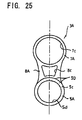
- Fig. 25 shows an eleventh embodiment of the fishline guide of the present invention.
- the fishline guide may also be constituted as, for example, a movable guide which is disposed on the fishing rod so as to be able to slide.
- a configuration may also be made in which a bent portion is not formed at the above-described frame 3. That is, as shown in Fig.
- a frame 3A is constituted into a flat plate form, on one end side, an opening 5d is formed as a fixing portion 5A (the opening 5d is provided at the fixing portion 5A), and on the other end side, an opening 7c, in which a guide ring can be fixed, is formed as a ring holding portion 7A.
- a cutout 8c is formed in a support leg portion 8A which connects the fixing portion 5A and the ring holding portion 7A.
- a sliding fixing ring 5c is mounted in the opening 5d, and by fixing a tubular body (not shown) in the opening 5d in which the sliding fixing ring 5c has been mounted, a stem of the fishing rod is engaged with a concavity/convexity portion formed in the inner surface of the tubular body.
- a configuration in which a bent portion is not formed at a frame may also be adopted in accordance with a mounting position of the fishing rod, and with respect to a prepreg which is used in the frame constituting such a fishline guide, a single layer structure made of a woven fabric layer may also be used.
- a laminated structure as described above may also be adopted, and a bent portion may also be separately formed.
- a portion (a region denoted by reference numeral 5D) where the sliding fixing ring 5c is mounted it is formed to be thicker than the ring holding portion 7A.
- the whole may also be formed in the same thickness, and a thickness or a shape can be arbitrarily set.
- the orientation directions of the reinforcing fibers in a plan view in a laminated state are in three or more directions, it becomes possible to efficiently improve strength while achieving a reduction in weight.
- the orientation directions of the reinforcing fibers of the prepreg constituting each layer or a lamination position of the prepreg is not particularly limited, but can be suitably modified. In this case, as described above, with respect to the outermost layers of the frame, it is preferable to dispose woven fabric layers so as to be able to effectively prevent breakage or the like.
- Fig. 26 shows a twelfth embodiment of the fishline guide of the present invention.
- the fishline guide 1 of this embodiment is the same as that of the eleventh embodiment in that the fixing portion 5 is formed into a tubular shape.
- the fixing portion 5 is not fixed to a fishing rod tube, but is made to be movable in the axial direction of the fishing rod tube, so that the fishline guide is made as a so-called movable guide which is fixed by fitting it to a suitable outer diameter portion of the fishing rod tube having a taper.
- the fixing portion 5 should have some degree of strength, it is preferable to set it to be thicker than at least the thickness of the ring holding portion 7.
- the frame 3 which is composed of the fixing portion 5, the ring holding portion 7, and the support leg portion 8 is integrally formed by laminating three or more layers prepregs in which reinforcing fibers are impregnated with resin.
- Fig. 27 shows a thirteenth embodiment of the fishline guide of the present invention.
- the fixing portion 5 and the support leg portion 8 are respectively provided so as to extend to both sides of the front and the back with the ring holding portion 7 as a center.
- the frame 3 which is composed of the fixing portion 5, the ring holding portion 7, and the support leg portion 8 is integrally formed by laminating three or more layers of prepreg in which reinforcing fibers are impregnated with resin.
- a coating film may also be formed on the whole or a portion of the frame.
- painting may also be performed, and vapor deposition of metal or ceramics may also be performed.
- the contact surface 5a may also be coated with a resin layer which is softer than the matrix resin of the lamination shaping material 20, or may also be made into a rough surface by applying paint with particles mixed therein on the contact surface 5a or forming concavity and convexity. Further, a coating film having a high antislip effect may also be formed on the contact surface 5a of the fixing portion 5.
- fixing may also be performed by exposing the reinforcing fibers of the lamination shaping material 20 at the contact surface 5a of the fixing portion 5 and placing the contact surface 5a where the reinforcing fibers are exposed, at the fishing rod tube 40.
- the guide ring 6 is fixed to the frame 3 after a surface treatment.
- a barrel processing may also be performed after fixing of the guide ring 6.
- Reinforcing fibers may also be disposed at the ring holding portion 7 to extend along the circumferential direction of the ring holding portion 7. In this case, by the reinforcing fibers extending along the circumferential direction, deformation of the opening 7a which is a portion in which the guide ring is set can be suppressed, and similarly to the aforesaid, a holding force for the guide ring 6 can be improved.
- the ring holding portion 7 (fishline passing hole portion) is formed into an annular shape.
- it is a shape capable of holding the guide ring 6, any shape may also be adopted.
- the ring holding portion 7 (fishline passing hole portion) may also be formed into a partly cut-out annular shape.
Landscapes
- Life Sciences & Earth Sciences (AREA)
- Environmental Sciences (AREA)
- Marine Sciences & Fisheries (AREA)
- Animal Husbandry (AREA)
- Biodiversity & Conservation Biology (AREA)
- Chemical & Material Sciences (AREA)
- Engineering & Computer Science (AREA)
- Composite Materials (AREA)
- Mechanical Engineering (AREA)
- Fishing Rods (AREA)
Claims (22)
- Verfahren zur Herstellung einer Führungseinrichtung (1) für eine Angelleine, umfassend:Bilden eines Plattenelements (30) durch thermisches Härten mehrerer laminierter faserverstärkter Prepregs (20), wobei die Verstärkungsfaser in den Prepregs mit Kunstharz imprägniert ist; undFormen eines Rahmens (3) aus dem Plattenelement (30).
- Verfahren nach Anspruch 1, wobei die Prepregs (20) in einem Zustand, in dem die Prepregs gebogen sind, thermisch gehärtet werden, so dass an dem Plattenelement (30) ein gebogener Abschnitt (10a, 10b) gebildet wird.
- Verfahren nach Anspruch 2, wobei die Prepregs (20) thermisch gehärtet werden, während sie an zumindest einem Abschnitt, der zu einem gebogenen Abschnitt des Rahmens geformt werden soll, gebogen sind.
- Verfahren nach Anspruch 2 oder 3, wobei
der Rahmen (3) einen Fixierungsabschnitt (5) zur Anbringung an einer Angelrute, einen Angelleinendurchgangsöffnungsabschnitt (7) und einen Halteschenkelabschnitt (8), welcher den Fixierungsabschnitt (5) mit dem Öffnungsabschnitt (7) verbindet, umfasst, und
der zumindest eine gebogene Abschnitt einen ersten gebogenen Abschnitt (10a) umfasst, der an einem Grenzabschnitt zwischen dem Fixierungsabschnitt (5) und dem Schenkelabschnitt (8) gebildet ist. - Verfahren nach Anspruch 4, wobei
der zumindest eine gebogene Abschnitt einen zweiten gebogenen Abschnitt (10b) umfasst, der an dem Schenkelabschnitt (8) gebildet ist,
wobei ein Biegewinkel des ersten gebogenen Abschnitts (10a) größer als ein Biegewinkel des zweiten gebogenen Abschnitts (10b) ist. - Verfahren nach einem der Ansprüche 1 bis 5, wobei der Rahmen (3) aus dem Plattenelement (30) geschnitten wird.
- Verfahren nach einem der Ansprüche 1 bis 6, wobei der Rahmen (3) auf eine solche Weise geformt wird, dass ein anderer Abschnitt des Plattenelements (30) als der dem Rahmen (3) entsprechende Abschnitt entfernt wird, um den Abschnitt, der dem Rahmen entspricht, zurückzulassen.
- Verfahren nach Anspruch 6 oder 7, wobei der Rahmen (3) durch Ausführen einer Presstätigkeit oder durch Ausschneiden des Rahmens durch eine Flüssigkeit oder ein Schneidewerkzeug geformt wird.
- Verfahren nach einem der Ansprüche 1 bis 8, ferner umfassend das Durchführen eines Oberflächenpolierprozesses an dem Rahmen (3) durch eine Trommelbearbeitung.
- Führungseinrichtung (1) für eine Angelleine, umfassend:einen Rahmen (3), der mehrere faserverstärkte Harzschichten umfasst, die durch Laminieren mehrerer faserverstärkter Prepregs (20), worin die Verstärkungsfaser mit Kunstharz imprägniert ist, gebildet sind.
- Führungseinrichtung für eine Angelleine nach Anspruch 10, wobei der Rahmen (3) einen Fixierungsabschnitt (5) zur Anbringung an einer Angelrute, einen Angelleinendurchgangsöffnungsabschnitt (7) und einen Halteschenkelabschnitt (8), welcher den Fixierungsabschnitt mit dem Öffnungsabschnitt verbindet, umfasst
- Führungseinrichtung für eine Angelleine nach Anspruch 11, wobei die mehreren faserverstärkten Harzschichten in einer Richtung laminiert sind, die im Wesentlichen senkrecht zu einer Ebene des Öffnungsabschnitts (7) verläuft.
- Führungseinrichtung für eine Angelleine nach einem der Ansprüche 10 bis 12, wobei zumindest drei der faserverstärkten Harzschichten laminiert sind.
- Führungseinrichtung für eine Angelleine nach einem der Ansprüche 10 bis 13, wobei die mehreren faserverstärkten Harzschichten so laminiert sind, dass sich die Fasern der mehreren faserverstärkten Harzschichten in zumindest drei verschiedene Richtungen erstrecken.
- Führungseinrichtung für eine Angelleine nach einem der Ansprüche 11 bis 14, wobei die mehreren faserverstärkten Harzschichten eine axiale Faser, die sich in eine Richtung von dem Fixierungsabschnitt zu dem Öffnungsabschnitt erstreckt, und eine schräge Faser, die sich schräg zu der Richtung von dem Fixierungsabschnitt zu dem Öffnungsabschnitt erstreckt, umfassen.
- Führungseinrichtung für eine Angelleine nach einem der Ansprüche 10 bis 15, wobei die mehreren faserverstärkten Harzschichten eine gewebefaserverstärkte Harzschicht umfassen, die an einer äußersten Schicht des Rahmens angeordnet ist.
- Führungseinrichtung für eine Angelleine nach Anspruch 11 bis 16, wobei die mehreren faserverstärkten Harzschichten
eine erste faserverstärkte Harzschicht mit einer Faser, die sich in einem ersten Winkel erstreckt, welcher schräg zu einer Längsrichtung, in die sich der Schenkelabschnitt erstreckt, verläuft;
eine zweite faserverstärkte Harzschicht mit einer Faser, die sich in einem zweiten Winkel erstreckt, welcher schräg zu der Längsrichtung verläuft,
umfassen,
wobei der erste und der zweite Winkel um die Längsrichtung symmetrisch sind, und die erste und die zweite faserverstärkte Harzschicht symmetrisch an entgegengesetzten Seiten einer Mittelplatte des Rahmens angeordnet sind. - Führungseinrichtung für eine Angelleine nach einem der Ansprüche 11 bis 15, wobei die mehreren faserverstärkten Harzschichten
eine erste faserverstärkte Harzschicht mit einer Faser, die sich in einem ersten Winkel erstreckt, welcher schräg zu einer Längsrichtung, in die sich der Schenkelabschnitt erstreckt, verläuft;
eine zweite faserverstärkte Harzschicht mit einer Faser, die sich in einem zweiten Winkel erstreckt, welcher schräg zu der Längsrichtung verläuft,
umfassen,
wobei der erste und der zweite Winkel um die Längsrichtung zueinander entgegengesetzt sind. - Führungseinrichtung für eine Angelleine nach einem der Ansprüche 11 bis 16, wobei die mehreren faserverstärkten Harzschichten
eine erste faserverstärkte Harzschicht mit einer Faser, die sich in eine Längsrichtung erstreckt, in die sich der Schenkelabschnitt erstreckt;
eine zweite faserverstärkte Harzschicht, die eine Faser aufweist, welche die Längsrichtung kreuzt, und die an einer Seite der ersten faserverstärkten Harzschicht angeordnet ist; und
eine dritte faserverstärkte Harzschicht, die eine Faser aufweist, welche die Längsrichtung kreuzt, und die an der anderen Seite der ersten faserverstärkten Harzschicht angeordnet ist,
umfassen. - Führungseinrichtung für eine Angelleine nach einem der Ansprüche 10 bis 19, wobei eine Seitenfläche des Rahmens auf eine solche Weise gebildet ist, dass die mehreren faserverstärkten Harzschichten, die an der Seitenfläche erscheinen, untereinander bündig ausgeführt sind.
- Führungseinrichtung für eine Angelleine nach einem der Ansprüche 11 bis 20, wobei die mehreren faserverstärkten Harzschichten eine faserverstärkte Harzschicht mit einer Faser, die sich in eine Längsrichtung erstreckt, in welche sich der Schenkelabschnitt erstreckt, umfassen.
- Führungseinrichtung für eine Angelleine nach einem der Ansprüche 11 bis 21, wobei
an einer Grenze zwischen dem Fixierungsabschnitt (5) und dem Schenkelabschnitt (8) ein gebogener Abschnitt (10a) gebildet ist, und
eine Verstärkungsschicht, die eine Verstärkungsfaser enthält, welche sich entlang des Schenkelabschnitts erstreckt, an dem gebogenen Abschnitt angeordnet ist.
Applications Claiming Priority (8)
| Application Number | Priority Date | Filing Date | Title |
|---|---|---|---|
| JP2009083178A JP5334305B2 (ja) | 2009-03-30 | 2009-03-30 | 釣糸ガイドの製造方法 |
| JP2009086666A JP5555441B2 (ja) | 2009-03-31 | 2009-03-31 | 釣り糸ガイド及び釣り竿 |
| JP2009086168A JP5334306B2 (ja) | 2009-03-31 | 2009-03-31 | 釣糸ガイド |
| JP2009151013A JP5558745B2 (ja) | 2009-06-25 | 2009-06-25 | 釣糸ガイド |
| JP2009268638 | 2009-11-26 | ||
| JP2009271562A JP5155285B2 (ja) | 2009-11-30 | 2009-11-30 | 釣糸ガイド |
| JP2010016496A JP5308367B2 (ja) | 2009-11-26 | 2010-01-28 | 釣糸ガイド |
| JP2010016499A JP5308368B2 (ja) | 2010-01-28 | 2010-01-28 | 釣糸ガイド |
Publications (2)
| Publication Number | Publication Date |
|---|---|
| EP2236026A1 EP2236026A1 (de) | 2010-10-06 |
| EP2236026B1 true EP2236026B1 (de) | 2012-05-23 |
Family
ID=42333419
Family Applications (1)
| Application Number | Title | Priority Date | Filing Date |
|---|---|---|---|
| EP10158473A Active EP2236026B1 (de) | 2009-03-30 | 2010-03-30 | Führungseinrichtung für Angelleine |
Country Status (3)
| Country | Link |
|---|---|
| US (2) | US8387302B2 (de) |
| EP (1) | EP2236026B1 (de) |
| KR (1) | KR101682242B1 (de) |
Families Citing this family (15)
| Publication number | Priority date | Publication date | Assignee | Title |
|---|---|---|---|---|
| JP4755670B2 (ja) * | 2008-05-19 | 2011-08-24 | 富士工業株式会社 | 釣糸ガイドおよび釣竿 |
| US8387302B2 (en) | 2009-03-30 | 2013-03-05 | Globeride, Inc. | Fishline guide |
| EP2742800B1 (de) | 2011-11-15 | 2017-04-05 | Globeride, Inc. | Angelschnurführung und angelrute damit |
| JP5944273B2 (ja) | 2012-08-31 | 2016-07-05 | グローブライド株式会社 | 釣竿 |
| KR101391116B1 (ko) * | 2013-07-23 | 2014-04-30 | 후지코교 가부시기가이샤 | 낚싯줄 가이드, 릴 시트 및 이를 구비한 낚싯대 |
| ITVI20130196A1 (it) * | 2013-07-30 | 2015-01-31 | Bona Carlo Della | Metodo per produrre un guida-filo per canne da pesca, guida-filo per canne da pesca e canna da pesca |
| JP2015047079A (ja) | 2013-08-30 | 2015-03-16 | グローブライド株式会社 | 釣糸ガイド、及び釣竿 |
| JP6386710B2 (ja) * | 2013-09-30 | 2018-09-05 | グローブライド株式会社 | 釣糸ガイド |
| US20160312863A1 (en) * | 2013-12-16 | 2016-10-27 | Borgwarner Inc. | Composite tensioner arm or guide for timing drive application |
| KR101524407B1 (ko) | 2014-05-23 | 2015-05-29 | 후지코교 가부시기가이샤 | 낚싯줄 가이드, 낚싯줄 가이드의 제조 방법 및 낚싯줄 가이드를 구비하는 낚싯대 |
| EP3424318B1 (de) * | 2016-02-29 | 2020-09-23 | Globeride, Inc. | Angelschnurführung, angelrute mit der angelschnurführung |
| US11647740B2 (en) * | 2017-02-27 | 2023-05-16 | Kyocera Corporation | Fishing line guide member and fishing rod provided with same |
| KR102200244B1 (ko) * | 2019-11-08 | 2021-01-08 | 후지코교 가부시기가이샤 | 낚싯줄 통과구 및 낚싯줄 통과구의 제조 방법 |
| KR102262018B1 (ko) * | 2020-03-10 | 2021-06-09 | 후지코교 가부시기가이샤 | 낚싯줄 가이드 및 낚싯줄 가이드를 포함하는 낚싯대 |
| CN113246490A (zh) * | 2021-04-30 | 2021-08-13 | 慈溪市永杰精工渔具有限公司 | 一种碳纤维导眼的制备方法 |
Family Cites Families (19)
| Publication number | Priority date | Publication date | Assignee | Title |
|---|---|---|---|---|
| US3769735A (en) * | 1971-08-02 | 1973-11-06 | Plas Steel Products Inc | Line guide attachment for fishing rods |
| JPS6095858A (ja) | 1983-10-31 | 1985-05-29 | Toshiba Corp | 燃料電池 |
| JPS6095858U (ja) | 1983-12-06 | 1985-06-29 | 富士工業株式会社 | 釣竿用導糸環 |
| JPS60151363A (ja) | 1984-01-18 | 1985-08-09 | 株式会社山東鉄工所 | 布帛の連続液処理装置 |
| JPS60196134A (ja) | 1984-03-19 | 1985-10-04 | ダイワ精工株式会社 | 釣竿用の釣糸ガイド及びその製造法 |
| US5347743A (en) | 1991-10-23 | 1994-09-20 | Shimano Inc. | Guide for use on a fishing rod |
| US5647162A (en) * | 1993-08-24 | 1997-07-15 | Daiwa Seiko, Inc. | Fishing rod with inserted fishline |
| JPH0838006A (ja) * | 1994-07-29 | 1996-02-13 | Daiwa Seiko Inc | 中通し釣竿 |
| JP2807970B2 (ja) * | 1994-08-10 | 1998-10-08 | 株式会社シマノ | 中通し竿及びその製造方法 |
| DE69517711T2 (de) * | 1994-11-16 | 2000-10-19 | Daiwa Seiko, Inc. | Angelrute mit Schnurinnenführung |
| JP2740638B2 (ja) * | 1994-12-27 | 1998-04-15 | 株式会社シマノ | 中通し竿 |
| JP3174806B2 (ja) | 1996-02-29 | 2001-06-11 | ダイワ精工株式会社 | 釣り糸案内具 |
| US6192615B1 (en) * | 1998-01-28 | 2001-02-27 | Daiwa Seiko, Inc. | Intraline fishing rod |
| JP3762577B2 (ja) | 1999-07-30 | 2006-04-05 | ダイワ精工株式会社 | 釣竿 |
| JP2002262725A (ja) | 2001-03-14 | 2002-09-17 | Johshuya Co Ltd | 釣糸案内ガイドの釣糸案内体及び釣糸案内ガイド |
| US7305792B2 (en) * | 2004-01-30 | 2007-12-11 | Daiwa Seiko, Inc. | Tip rod |
| JP4652136B2 (ja) | 2005-06-09 | 2011-03-16 | 富士工業株式会社 | ラインガイド用フレームおよび釣竿 |
| US8387302B2 (en) | 2009-03-30 | 2013-03-05 | Globeride, Inc. | Fishline guide |
| JP5334305B2 (ja) | 2009-03-30 | 2013-11-06 | グローブライド株式会社 | 釣糸ガイドの製造方法 |
-
2010
- 2010-03-29 US US12/662,039 patent/US8387302B2/en active Active
- 2010-03-29 KR KR1020100027765A patent/KR101682242B1/ko active Active
- 2010-03-30 EP EP10158473A patent/EP2236026B1/de active Active
-
2013
- 2013-02-14 US US13/767,617 patent/US9930873B2/en active Active
Also Published As
| Publication number | Publication date |
|---|---|
| EP2236026A1 (de) | 2010-10-06 |
| KR101682242B1 (ko) | 2016-12-05 |
| KR20100109450A (ko) | 2010-10-08 |
| US9930873B2 (en) | 2018-04-03 |
| US8387302B2 (en) | 2013-03-05 |
| US20130192120A1 (en) | 2013-08-01 |
| US20100263257A1 (en) | 2010-10-21 |
Similar Documents
| Publication | Publication Date | Title |
|---|---|---|
| US9930873B2 (en) | Fishline guide | |
| KR101817803B1 (ko) | 낚싯줄 가이드 및 그 제조 방법 | |
| JP6386710B2 (ja) | 釣糸ガイド | |
| JP5558745B2 (ja) | 釣糸ガイド | |
| JP5555441B2 (ja) | 釣り糸ガイド及び釣り竿 | |
| JP5460441B2 (ja) | 釣糸ガイド及びその製造方法 | |
| JP5334305B2 (ja) | 釣糸ガイドの製造方法 | |
| US10888074B2 (en) | Fishing line guide and fishing rod with the same | |
| JP5155285B2 (ja) | 釣糸ガイド | |
| JP2012075374A (ja) | 釣糸ガイド及び釣竿 | |
| JP2011205998A (ja) | 釣糸ガイド及びその製造方法 | |
| JP5759697B2 (ja) | 釣糸ガイド及びその製造方法 | |
| JP5308368B2 (ja) | 釣糸ガイド | |
| CN103039413B (zh) | 钓线导向件 | |
| JP5334306B2 (ja) | 釣糸ガイド | |
| JP5431283B2 (ja) | 釣糸ガイド | |
| KR101763532B1 (ko) | 낚싯줄 가이드 | |
| JP5738956B2 (ja) | 釣糸ガイド | |
| JP5308367B2 (ja) | 釣糸ガイド | |
| JP5546608B2 (ja) | 釣糸ガイド | |
| JP5546609B2 (ja) | 釣糸ガイド | |
| JP5702012B2 (ja) | 釣糸ガイドの製造方法 | |
| JP5616484B2 (ja) | 釣糸ガイド及びその製造方法 | |
| JP2011239776A (ja) | 釣り糸ガイド |
Legal Events
| Date | Code | Title | Description |
|---|---|---|---|
| PUAI | Public reference made under article 153(3) epc to a published international application that has entered the european phase |
Free format text: ORIGINAL CODE: 0009012 |
|
| AK | Designated contracting states |
Kind code of ref document: A1 Designated state(s): AT BE BG CH CY CZ DE DK EE ES FI FR GB GR HR HU IE IS IT LI LT LU LV MC MK MT NL NO PL PT RO SE SI SK SM TR |
|
| AX | Request for extension of the european patent |
Extension state: AL BA ME RS |
|
| 17P | Request for examination filed |
Effective date: 20110405 |
|
| GRAP | Despatch of communication of intention to grant a patent |
Free format text: ORIGINAL CODE: EPIDOSNIGR1 |
|
| RIC1 | Information provided on ipc code assigned before grant |
Ipc: A01K 87/04 20060101AFI20110922BHEP |
|
| GRAS | Grant fee paid |
Free format text: ORIGINAL CODE: EPIDOSNIGR3 |
|
| RIN1 | Information on inventor provided before grant (corrected) |
Inventor name: TURUFUJI, TOMOYOSHI Inventor name: NAITOU, HIDEYUKI Inventor name: WATANABE, MASAYUKI Inventor name: MORI, HIROYUKI Inventor name: AKIBA, MASARU Inventor name: SAITOU, ATUSHI Inventor name: SUGAYA, EIJI |
|
| GRAA | (expected) grant |
Free format text: ORIGINAL CODE: 0009210 |
|
| AK | Designated contracting states |
Kind code of ref document: B1 Designated state(s): AT BE BG CH CY CZ DE DK EE ES FI FR GB GR HR HU IE IS IT LI LT LU LV MC MK MT NL NO PL PT RO SE SI SK SM TR |
|
| REG | Reference to a national code |
Ref country code: GB Ref legal event code: FG4D |
|
| REG | Reference to a national code |
Ref country code: CH Ref legal event code: EP |
|
| REG | Reference to a national code |
Ref country code: AT Ref legal event code: REF Ref document number: 558611 Country of ref document: AT Kind code of ref document: T Effective date: 20120615 |
|
| REG | Reference to a national code |
Ref country code: IE Ref legal event code: FG4D |
|
| REG | Reference to a national code |
Ref country code: DE Ref legal event code: R096 Ref document number: 602010001604 Country of ref document: DE Effective date: 20120719 |
|
| REG | Reference to a national code |
Ref country code: NL Ref legal event code: VDEP Effective date: 20120523 |
|
| REG | Reference to a national code |
Ref country code: LT Ref legal event code: MG4D Effective date: 20120523 |
|
| PG25 | Lapsed in a contracting state [announced via postgrant information from national office to epo] |
Ref country code: LT Free format text: LAPSE BECAUSE OF FAILURE TO SUBMIT A TRANSLATION OF THE DESCRIPTION OR TO PAY THE FEE WITHIN THE PRESCRIBED TIME-LIMIT Effective date: 20120523 Ref country code: IS Free format text: LAPSE BECAUSE OF FAILURE TO SUBMIT A TRANSLATION OF THE DESCRIPTION OR TO PAY THE FEE WITHIN THE PRESCRIBED TIME-LIMIT Effective date: 20120923 Ref country code: SE Free format text: LAPSE BECAUSE OF FAILURE TO SUBMIT A TRANSLATION OF THE DESCRIPTION OR TO PAY THE FEE WITHIN THE PRESCRIBED TIME-LIMIT Effective date: 20120523 Ref country code: FI Free format text: LAPSE BECAUSE OF FAILURE TO SUBMIT A TRANSLATION OF THE DESCRIPTION OR TO PAY THE FEE WITHIN THE PRESCRIBED TIME-LIMIT Effective date: 20120523 Ref country code: NO Free format text: LAPSE BECAUSE OF FAILURE TO SUBMIT A TRANSLATION OF THE DESCRIPTION OR TO PAY THE FEE WITHIN THE PRESCRIBED TIME-LIMIT Effective date: 20120823 |
|
| REG | Reference to a national code |
Ref country code: AT Ref legal event code: MK05 Ref document number: 558611 Country of ref document: AT Kind code of ref document: T Effective date: 20120523 |
|
| PG25 | Lapsed in a contracting state [announced via postgrant information from national office to epo] |
Ref country code: SI Free format text: LAPSE BECAUSE OF FAILURE TO SUBMIT A TRANSLATION OF THE DESCRIPTION OR TO PAY THE FEE WITHIN THE PRESCRIBED TIME-LIMIT Effective date: 20120523 Ref country code: LV Free format text: LAPSE BECAUSE OF FAILURE TO SUBMIT A TRANSLATION OF THE DESCRIPTION OR TO PAY THE FEE WITHIN THE PRESCRIBED TIME-LIMIT Effective date: 20120523 Ref country code: GR Free format text: LAPSE BECAUSE OF FAILURE TO SUBMIT A TRANSLATION OF THE DESCRIPTION OR TO PAY THE FEE WITHIN THE PRESCRIBED TIME-LIMIT Effective date: 20120824 Ref country code: PT Free format text: LAPSE BECAUSE OF FAILURE TO SUBMIT A TRANSLATION OF THE DESCRIPTION OR TO PAY THE FEE WITHIN THE PRESCRIBED TIME-LIMIT Effective date: 20120924 Ref country code: HR Free format text: LAPSE BECAUSE OF FAILURE TO SUBMIT A TRANSLATION OF THE DESCRIPTION OR TO PAY THE FEE WITHIN THE PRESCRIBED TIME-LIMIT Effective date: 20120523 |
|
| PG25 | Lapsed in a contracting state [announced via postgrant information from national office to epo] |
Ref country code: BE Free format text: LAPSE BECAUSE OF FAILURE TO SUBMIT A TRANSLATION OF THE DESCRIPTION OR TO PAY THE FEE WITHIN THE PRESCRIBED TIME-LIMIT Effective date: 20120523 |
|
| PG25 | Lapsed in a contracting state [announced via postgrant information from national office to epo] |
Ref country code: AT Free format text: LAPSE BECAUSE OF FAILURE TO SUBMIT A TRANSLATION OF THE DESCRIPTION OR TO PAY THE FEE WITHIN THE PRESCRIBED TIME-LIMIT Effective date: 20120523 Ref country code: EE Free format text: LAPSE BECAUSE OF FAILURE TO SUBMIT A TRANSLATION OF THE DESCRIPTION OR TO PAY THE FEE WITHIN THE PRESCRIBED TIME-LIMIT Effective date: 20120523 Ref country code: DK Free format text: LAPSE BECAUSE OF FAILURE TO SUBMIT A TRANSLATION OF THE DESCRIPTION OR TO PAY THE FEE WITHIN THE PRESCRIBED TIME-LIMIT Effective date: 20120523 Ref country code: SK Free format text: LAPSE BECAUSE OF FAILURE TO SUBMIT A TRANSLATION OF THE DESCRIPTION OR TO PAY THE FEE WITHIN THE PRESCRIBED TIME-LIMIT Effective date: 20120523 Ref country code: CZ Free format text: LAPSE BECAUSE OF FAILURE TO SUBMIT A TRANSLATION OF THE DESCRIPTION OR TO PAY THE FEE WITHIN THE PRESCRIBED TIME-LIMIT Effective date: 20120523 Ref country code: NL Free format text: LAPSE BECAUSE OF FAILURE TO SUBMIT A TRANSLATION OF THE DESCRIPTION OR TO PAY THE FEE WITHIN THE PRESCRIBED TIME-LIMIT Effective date: 20120523 Ref country code: RO Free format text: LAPSE BECAUSE OF FAILURE TO SUBMIT A TRANSLATION OF THE DESCRIPTION OR TO PAY THE FEE WITHIN THE PRESCRIBED TIME-LIMIT Effective date: 20120523 |
|
| PG25 | Lapsed in a contracting state [announced via postgrant information from national office to epo] |
Ref country code: PL Free format text: LAPSE BECAUSE OF FAILURE TO SUBMIT A TRANSLATION OF THE DESCRIPTION OR TO PAY THE FEE WITHIN THE PRESCRIBED TIME-LIMIT Effective date: 20120523 |
|
| PLBE | No opposition filed within time limit |
Free format text: ORIGINAL CODE: 0009261 |
|
| STAA | Information on the status of an ep patent application or granted ep patent |
Free format text: STATUS: NO OPPOSITION FILED WITHIN TIME LIMIT |
|
| 26N | No opposition filed |
Effective date: 20130226 |
|
| REG | Reference to a national code |
Ref country code: DE Ref legal event code: R097 Ref document number: 602010001604 Country of ref document: DE Effective date: 20130226 |
|
| PG25 | Lapsed in a contracting state [announced via postgrant information from national office to epo] |
Ref country code: BG Free format text: LAPSE BECAUSE OF FAILURE TO SUBMIT A TRANSLATION OF THE DESCRIPTION OR TO PAY THE FEE WITHIN THE PRESCRIBED TIME-LIMIT Effective date: 20120823 |
|
| PG25 | Lapsed in a contracting state [announced via postgrant information from national office to epo] |
Ref country code: MC Free format text: LAPSE BECAUSE OF NON-PAYMENT OF DUE FEES Effective date: 20130331 Ref country code: ES Free format text: LAPSE BECAUSE OF FAILURE TO SUBMIT A TRANSLATION OF THE DESCRIPTION OR TO PAY THE FEE WITHIN THE PRESCRIBED TIME-LIMIT Effective date: 20120903 |
|
| REG | Reference to a national code |
Ref country code: IE Ref legal event code: MM4A |
|
| PG25 | Lapsed in a contracting state [announced via postgrant information from national office to epo] |
Ref country code: IE Free format text: LAPSE BECAUSE OF NON-PAYMENT OF DUE FEES Effective date: 20130330 |
|
| PG25 | Lapsed in a contracting state [announced via postgrant information from national office to epo] |
Ref country code: MT Free format text: LAPSE BECAUSE OF FAILURE TO SUBMIT A TRANSLATION OF THE DESCRIPTION OR TO PAY THE FEE WITHIN THE PRESCRIBED TIME-LIMIT Effective date: 20120523 |
|
| REG | Reference to a national code |
Ref country code: CH Ref legal event code: PL |
|
| PG25 | Lapsed in a contracting state [announced via postgrant information from national office to epo] |
Ref country code: LI Free format text: LAPSE BECAUSE OF NON-PAYMENT OF DUE FEES Effective date: 20140331 Ref country code: CH Free format text: LAPSE BECAUSE OF NON-PAYMENT OF DUE FEES Effective date: 20140331 |
|
| PG25 | Lapsed in a contracting state [announced via postgrant information from national office to epo] |
Ref country code: SM Free format text: LAPSE BECAUSE OF FAILURE TO SUBMIT A TRANSLATION OF THE DESCRIPTION OR TO PAY THE FEE WITHIN THE PRESCRIBED TIME-LIMIT Effective date: 20120523 |
|
| PG25 | Lapsed in a contracting state [announced via postgrant information from national office to epo] |
Ref country code: TR Free format text: LAPSE BECAUSE OF FAILURE TO SUBMIT A TRANSLATION OF THE DESCRIPTION OR TO PAY THE FEE WITHIN THE PRESCRIBED TIME-LIMIT Effective date: 20120523 Ref country code: CY Free format text: LAPSE BECAUSE OF FAILURE TO SUBMIT A TRANSLATION OF THE DESCRIPTION OR TO PAY THE FEE WITHIN THE PRESCRIBED TIME-LIMIT Effective date: 20120523 |
|
| PG25 | Lapsed in a contracting state [announced via postgrant information from national office to epo] |
Ref country code: MK Free format text: LAPSE BECAUSE OF FAILURE TO SUBMIT A TRANSLATION OF THE DESCRIPTION OR TO PAY THE FEE WITHIN THE PRESCRIBED TIME-LIMIT Effective date: 20120523 Ref country code: HU Free format text: LAPSE BECAUSE OF FAILURE TO SUBMIT A TRANSLATION OF THE DESCRIPTION OR TO PAY THE FEE WITHIN THE PRESCRIBED TIME-LIMIT; INVALID AB INITIO Effective date: 20100330 Ref country code: LU Free format text: LAPSE BECAUSE OF NON-PAYMENT OF DUE FEES Effective date: 20130330 |
|
| REG | Reference to a national code |
Ref country code: FR Ref legal event code: PLFP Year of fee payment: 7 |
|
| REG | Reference to a national code |
Ref country code: FR Ref legal event code: PLFP Year of fee payment: 8 |
|
| REG | Reference to a national code |
Ref country code: FR Ref legal event code: PLFP Year of fee payment: 9 |
|
| REG | Reference to a national code |
Ref country code: DE Ref legal event code: R081 Ref document number: 602010001604 Country of ref document: DE Owner name: GLOBERIDE, INC., HIGASHIKURUME-SHI, JP Free format text: FORMER OWNER: GLOBERIDE, INC., HIGASHI KURUME, TOKYO, JP |
|
| P01 | Opt-out of the competence of the unified patent court (upc) registered |
Effective date: 20230414 |
|
| PGFP | Annual fee paid to national office [announced via postgrant information from national office to epo] |
Ref country code: GB Payment date: 20260209 Year of fee payment: 17 |
|
| PGFP | Annual fee paid to national office [announced via postgrant information from national office to epo] |
Ref country code: DE Payment date: 20260204 Year of fee payment: 17 |
|
| PGFP | Annual fee paid to national office [announced via postgrant information from national office to epo] |
Ref country code: IT Payment date: 20260220 Year of fee payment: 17 |
|
| PGFP | Annual fee paid to national office [announced via postgrant information from national office to epo] |
Ref country code: FR Payment date: 20260209 Year of fee payment: 17 |