EP2221480A2 - Spiralverdichter - Google Patents
Spiralverdichter Download PDFInfo
- Publication number
- EP2221480A2 EP2221480A2 EP10001731A EP10001731A EP2221480A2 EP 2221480 A2 EP2221480 A2 EP 2221480A2 EP 10001731 A EP10001731 A EP 10001731A EP 10001731 A EP10001731 A EP 10001731A EP 2221480 A2 EP2221480 A2 EP 2221480A2
- Authority
- EP
- European Patent Office
- Prior art keywords
- scroll
- pin
- intercommunication path
- intercommunication
- path
- Prior art date
- Legal status (The legal status is an assumption and is not a legal conclusion. Google has not performed a legal analysis and makes no representation as to the accuracy of the status listed.)
- Granted
Links
- 238000003780 insertion Methods 0.000 claims abstract description 39
- 230000037431 insertion Effects 0.000 claims abstract description 39
- 239000003921 oil Substances 0.000 description 25
- 230000006835 compression Effects 0.000 description 22
- 238000007906 compression Methods 0.000 description 22
- 239000003507 refrigerant Substances 0.000 description 22
- 238000010276 construction Methods 0.000 description 10
- 239000010687 lubricating oil Substances 0.000 description 8
- 230000001105 regulatory effect Effects 0.000 description 5
- 230000001419 dependent effect Effects 0.000 description 4
- 238000000034 method Methods 0.000 description 4
- 230000002093 peripheral effect Effects 0.000 description 4
- 238000004519 manufacturing process Methods 0.000 description 3
- 230000003746 surface roughness Effects 0.000 description 3
- 239000000853 adhesive Substances 0.000 description 1
- 230000008602 contraction Effects 0.000 description 1
- 238000005520 cutting process Methods 0.000 description 1
- 238000010586 diagram Methods 0.000 description 1
- 238000007599 discharging Methods 0.000 description 1
- 238000003754 machining Methods 0.000 description 1
- 238000012986 modification Methods 0.000 description 1
- 230000004048 modification Effects 0.000 description 1
- 230000000149 penetrating effect Effects 0.000 description 1
- 238000005057 refrigeration Methods 0.000 description 1
Images
Classifications
-
- F—MECHANICAL ENGINEERING; LIGHTING; HEATING; WEAPONS; BLASTING
- F04—POSITIVE - DISPLACEMENT MACHINES FOR LIQUIDS; PUMPS FOR LIQUIDS OR ELASTIC FLUIDS
- F04C—ROTARY-PISTON, OR OSCILLATING-PISTON, POSITIVE-DISPLACEMENT MACHINES FOR LIQUIDS; ROTARY-PISTON, OR OSCILLATING-PISTON, POSITIVE-DISPLACEMENT PUMPS
- F04C29/00—Component parts, details or accessories of pumps or pumping installations, not provided for in groups F04C18/00 - F04C28/00
- F04C29/02—Lubrication; Lubricant separation
- F04C29/028—Means for improving or restricting lubricant flow
-
- F—MECHANICAL ENGINEERING; LIGHTING; HEATING; WEAPONS; BLASTING
- F04—POSITIVE - DISPLACEMENT MACHINES FOR LIQUIDS; PUMPS FOR LIQUIDS OR ELASTIC FLUIDS
- F04C—ROTARY-PISTON, OR OSCILLATING-PISTON, POSITIVE-DISPLACEMENT MACHINES FOR LIQUIDS; ROTARY-PISTON, OR OSCILLATING-PISTON, POSITIVE-DISPLACEMENT PUMPS
- F04C18/00—Rotary-piston pumps specially adapted for elastic fluids
- F04C18/02—Rotary-piston pumps specially adapted for elastic fluids of arcuate-engagement type, i.e. with circular translatory movement of co-operating members, each member having the same number of teeth or tooth-equivalents
- F04C18/0207—Rotary-piston pumps specially adapted for elastic fluids of arcuate-engagement type, i.e. with circular translatory movement of co-operating members, each member having the same number of teeth or tooth-equivalents both members having co-operating elements in spiral form
- F04C18/0246—Details concerning the involute wraps or their base, e.g. geometry
- F04C18/0253—Details concerning the base
-
- F—MECHANICAL ENGINEERING; LIGHTING; HEATING; WEAPONS; BLASTING
- F04—POSITIVE - DISPLACEMENT MACHINES FOR LIQUIDS; PUMPS FOR LIQUIDS OR ELASTIC FLUIDS
- F04C—ROTARY-PISTON, OR OSCILLATING-PISTON, POSITIVE-DISPLACEMENT MACHINES FOR LIQUIDS; ROTARY-PISTON, OR OSCILLATING-PISTON, POSITIVE-DISPLACEMENT PUMPS
- F04C23/00—Combinations of two or more pumps, each being of rotary-piston or oscillating-piston type, specially adapted for elastic fluids; Pumping installations specially adapted for elastic fluids; Multi-stage pumps specially adapted for elastic fluids
- F04C23/008—Hermetic pumps
Definitions
- the present invention relates to a scroll type compressor having an oil path through which lubricating oil is supplied to engagement portions at a low-pressure side between a fixed scroll and a movable scroll.
- the restriction of the flow rate is dependent on the size of the spiral passage formed on the outer periphery of the main body, and thus the processing precision (machining performance) of the spiral passage has been required to be high, so that it has been difficult to process the spiral passage.
- an object of the present invention is to provide a scroll type compressor that can restrict the flow rate of lubricating oil without requiring a high processing precision and can be manufactured in low cost.
- a scroll type compressor comprising: a fixed scroll; a movable scroll engaged with the fixed scroll; and a hermetically sealed container in which the fixed scroll and the movable scroll are mounted, wherein one scroll of the fixed scroll and the movable scroll includes: an intercommunication path that is opened to the outside of the one scroll at one end thereof, extends substantially in a radial direction of the one scroll, has a high-pressure opening intercommunicating with a high-pressure portion of the hermetically sealed container and a low-pressure opening intercommunicating with a low-pressure portion in the one scroll, and has a lower hole opened to the outside of the one scroll and an insertion hole formed by subjecting the lower hole to reaming processing from the one end to a position of a predetermined depth of the lower hole, oil being supplied from the high-pressure opening through the inside of the intercommunication path to the low-pressure opening; a pin member that is configured to be slightly smaller in diameter than the intercommunication path and movably inserted
- the intercommunication path is constructed by forming the lower hole opened to the outside at one end thereof and then executing reaming processing (reamer processing) on the lower hole till the position of the predetermined depth to form the insertion hole. Therefore, the surface roughness of the inner surface of the insertion hole can be reduced (that is, the smoothness of the inner surface can be enhanced), and thus the gap between the inner diameter of the insertion hole and the outer diameter of the pin member inserted in the insertion hole can be remarkably properly managed. Therefore, the flow rate of the lubricating oil directing from the high-pressure side to the low-pressure side can be properly regulated (restricted).
- the pin member may comprise a first pin fitted in the lower hole at the back side of the intercommunication path, and a second pin that is brought into contact with the first pin and fitted in the insertion hole.
- a channel through which lubricating oil flows may be formed in the gap between the lower hole and the first pin fitted in the lower hole, and the size of the gap does not so much contribute to the regulation (restriction) of the flow rate.
- the size of the gap between the insertion hole and the second pin fitted in the insertion hole greatly contributes to the regulation (restriction) of the flow rate.
- the insertion hole is finished by the reaming (reamer) processing, and thus the finishing precision of the inner diameter of the insertion hole is enhanced.
- the gap between the inner diameter of the insertion hole and the outer diameter of the pin member inserted in the insertion hole can be remarkably properly managed. Accordingly, the flow rate of the lubricating oil flowing from the high-pressure side to the low-pressure side can be properly regulated (restricted) can be properly regulated (restricted) by the gap concerned.
- the pin member in the above construction, it is unnecessary to process the pin member, and when the original shape of the pin member is cylindrical, the pin member can be directly used without modifying the shape. Therefore, it is not dependent on the processing precision, and also the manufacturing cost of the pin member can be reduced.
- the first pin and the second pin may be integrated with each other.
- the number of parts of the pin member can be reduced, and also the assembly of the parts and the exchange of the pin member can be easily performed.
- the substantially conical processing trace of the tip of the drill is left at the end of the back side of the lower hole described above. Accordingly, if the substantially conical tip portion fitted to the processing trace is formed at the tip of the first pin 155A of the integrated pin member 155, when the pin member 155 is inserted into the intercommunication hole 51 and the screwmember is screwed into the intercommunication hole, the intercommunication hole and the pin member can be easily set to be coaxial with each other, and the gap between the inner diameter of the insertion hole and the outer diameter of the second portion can be properly managed. Accordingly, the flow rate of the lubricating oil directing from the high-pressure side to the low-pressure side can be properly regulated (restricted) by the gap.
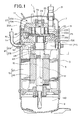
- reference numeral 1 represents a scroll type compressor having a high internal pressure.
- the compressor 1 is connected to a refrigerant circuit (not shown) in which refrigerant is circulated to perform a refrigeration cycle operation, and compresses the refrigerant.
- the compressor 1 has a hermetically-sealed dome type casing 3 which is designed in an elongated cylindrical shape.
- the casing 3 is constructed as a pressure container by a casing main body 5 as a cylindrical body portion having an axis line in the up-and-down direction, a saucer-shaped upper cap 7 which is air-tightly welded and integrally joined to the upper end portion of the casing main body 5 and has an upwardly projecting convex surface, and a saucer-shaped lower cap 7 having a downwardly projecting convex surface, and the inside of the casing 3 is designed to have a cavity.
- a scroll compression mechanism 11 for compressing refrigerant, and a driving motor 13 disposed below the scroll compression mechanism 11 are mounted in the casing 3.
- the scroll compression mechanism 11 and he driving motor 13 are connected to each other through a driving shaft 15 which is disposed so as to extend in the up-and-down direction in the casing 3.
- a gap space 17 is formed between the scroll compression mechanism 11 and the driving motor 13.
- the scroll compression mechanism 11 has a housing 21 as a substantially cylindrical accommodating member which is opened at the upper side thereof and has a bottom, a fixed scroll 23 which is disposed in close contact with the upper surface of the housing 21, and a movable scroll 25 which is disposed between the fixed scroll 23 and the housing 21 and engaged with the fixed scroll 23.
- the housing 21 is press-fitted in the casing main body 5 over the whole outer peripheral surface thereof in the peripheral direction.
- the inside of the casing 3 is compartmented into a high pressure space 27 at the lower side of the housing 21 and a discharge space 29 at the upper side of the housing 21, and the respective spaces 27 and 29 intercommunicate with each other through a longitudinal groove (passage ) 71 which is formed on the outer peripheries of the housing 21 and the fixed scroll 23 so as to extend longitudinally.
- the housing 21 is provided with a housing space 21A in which an eccentric axial portion 15A of the driving shaft 15 is rotated, and a radial bearing portion 21B extending downwardly from the center of the lower surface of the housing 21. Furthermore, the housing 21 is provided with a radial bearing hole 28 penetrating between the lower end surface of the radial bearing portion 21B and the bottom surface of the housing space 21A, and the upper end portion of the driving shaft 15 is rotatably fitted and mounted through the radial bearing 30 in the radial bearing hole 28.
- a suction pipe 31 for leading the refrigerant in the refrigerant circuit to the scroll compression mechanism 11 penetrates through the upper cap 7 of the casing 3 and is air-tightly fixed to the upper cap 7, and a discharge pipe 33 for discharging the refrigerant in the casing 3 to the outside of the casing 3 penetrates through the casing main body 5 and is air-tightly fixed to the casing main body 5.
- the suction pipe 31 extends in the up-and-down direction in the discharge space 29, and the inner end portion of the suction pipe 31 penetrates through a suction port 32 opened to the fixed scroll 23 of the scroll compression mechanism 11, and intercommunicates with the compression chamber 35. Accordingly, the refrigerant is sucked into the compression chamber 35 through the suction pipe 31.
- the driving motor 13 has an annular stator 37 fixed to the inner wall surface of the casing 3, and a rotor 39 which is freely rotatably provided inside the stator 37, the motor 13 is constructed by a DC motor, and the movable scroll 25 of the scroll compression mechanism 11 is connected to the rotor 39 through the driving shaft 15.
- the lower space 40 at the lower side of the driving motor 13 is kept to a high-pressure state, and oil is stocked at the inner bottom portion of the lower cap 9 corresponding to the lower end portion of the lower space 40.
- An oil supply path 41 as a part of a high-pressure oil supply unit is formed in the driving shaft 15, the oil supply path 41 intercommunicates with an oil chamber 43 at the back side of the movable scroll 25.
- a pickup 45 is connected to the lower end of the driving shaft 15, and the pickup 45 scoops up the oil stocked at the inner bottom portion of the lower cap 9.
- the scooped oil is passed through the oil supply path 41 of the driving shaft 15 and supplied to the oil chamber 43 at the back side of the movable scroll 25, and supplied from the oil chamber 43 to each sliding portion and the compression chamber 35 of the scroll compression mechanism 11 through an intercommunication path 51 provided to the movable scroll 25.
- the fixed scroll 23 comprises a mirror plate 23A and a scroll-like (involute type) lap 23b formed on the lower surface of the mirror plate 23A.
- the movable scroll 25 comprises a mirror plate 25A and a scroll-type (involute type) lap 25B formed on the upper surface of the mirror plate 25A.
- the lap 23B of the fixed scroll 23 and the lap 25B of the movable scroll 25 are engaged with each other, whereby plural compression chambers 35 are formed by both the laps 23B and 25B between the fixed scroll 23 and the movable scroll 25.
- the movable scroll 25 is supported through the Oldham's ring 61 by the fixed scroll 23, and a cylindrical boss portion 25C having a bottom is projected from the center portion of the lower surface of the mirror plate 25A. Furthermore, an eccentric shaft portion 15A is provided to the upper end of the driving shaft 15, and the eccentric shaft portion 15A is rotatably fitted in the boss portion 25C of the movable scroll 25.
- a counter weight portion 63 is provided to the driving shaft 15 at the lower side of the radial bearing portion 21B of the housing 21 in order to establish dynamic balance with the movable scroll 25, the eccentric shaft portion 15A, etc..
- the driving shaft 15 rotates while keeping the weight balance by the counter weight portion 63, whereby the movable scroll 25 does not rotate on its axis, but swirls.
- the compression chamber 35 is configured so that in connection with the swirling of the movable scroll 25, the refrigerant sucked by the suction pipe 31 is compressed due to contraction of the volume between both the laps 23B and 25B.
- a discharge hole 73 is provided at the center portion of the fixed scroll 23, and gas refrigerant discharged from the discharge hole 73 is passed through the discharge valve 75 and discharged to the discharge space 29, and flows out into the high-pressure space 27 at the lower side of the housing 21 through a longitudinal groove 71 formed on the respective outer peripheries of the housing 21 and the fixed scroll 23.
- This high-pressure refrigerant is discharged to the outside of the casing 3 through the discharge pipe 33 provided to the casing main body 5.
- a guide member (gas flow deflecting member) 77 is provided to the lower side of the longitudinal groove 71.
- the guide member 77 deflects the flow direction of the gas refrigerant (which is discharged from the discharge valve 75 to the discharge space 29, passed through the longitudinal groove 71 and flows downwardly) toward a shielding plate 79 and/or in the horizontal direction along the inner surface of the casing main body 5 (casing 3), and also guides the gas refrigerant through a passage between the shielding plate 79 at the upper side of the coil end 81 of the driving motor 13 and the inner surface of the casing main body 5 (casing 3) and then to the discharge pipe 33.
- the driving motor 13 When the driving motor 13 is driven, the rotor 39 rotates relative to the stator 37, and thus the driving shaft 15 rotates.
- the driving shaft 15 rotates, the movable scroll 25 of the scroll compression mechanism 11 does not rotate on its axis, but makes only the swirling motion relative to the fixed scroll 23. Accordingly, low-pressure refrigerant is passed through the suction pipe 31, and sucked from the peripheral edge side of the compression chamber 35 into the compression chamber 35, so that this refrigerant is compressed in connection with volume variation of the compression chamber 35.
- the compressed refrigerant is increased in pressure, passed from the compression chamber 35 to the discharge valve 75, and discharged to the discharge space 29.
- the refrigerant is passed through the longitudinal groove 71 formed on the respective outer peripheries of the housing 21 and the fixed scroll 23, and then flows out to the high-pressure space at the lower side of the housing 21. Still further, this high-pressure refrigerant is discharged through the discharge pipe 33 provided to the casing main body 5 to the outside of the casing 3. After the refrigerant discharged to the outside of the casing 3 is circulated in the refrigerant circuit (not shown), the refrigerant is sucked through the suction pipe 31 into the compressor 1 again, and compressed in the compressor. The circulation of the refrigerant as described above is repeated.
- Oil stocked in the inner bottom portion of the lower cap of the casing 3 is scooped up by the pickup 45 provided to the lower end of the driving shaft 15, and this oil is passed through an oil path 41 of the driving shaft 15, supplied to an oil chamber 43 at the back side of the movable scroll 25, and then supplied from the oil chamber 43 through an intercommunication path 51 provided to the movable scroll 25 to each of sliding portions of the scroll compressor mechanism 11 and the compression chamber 35.
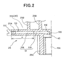
- Fig. 2 is an enlarged view of the intercommunication path 51 provided to the movable scroll 25.
- the mirror plate 25A of the movable scroll 25 is provided with the intercommunication path 51 which is opened outwardly at one end thereof and extends linearly (in a radial direction of the movable scroll 25) inwardly.
- the intercommunication path 51 is formed by first forming a lower hole 51A of an intercommunication path whose one end is opened outwardly.
- a substantially conical processing trace 51E which is conformed with the tip of a drill in shape is left at the leading-edge of the lower hole 51A.
- reaming processing is conducted from one end to a position of a predetermined depth H on the lower hole 51A to form an insertion hole 51B which extends to the predetermined depth H and has a lower surface roughness (i.e., higher smoothness) than the lower hole 51A.
- a minute step portion (stopper portion) 52 is formed at the rear end of the insertion hole 51B, that is, the boundary between the insertion hole 51B and the lower hole 51A.
- a female screw hole 51C is formed at an inlet port of the insertion hole 51B.
- the other end (high-pressure opening) of the intercommunication path 51 is bent in a substantially L-shape, and intercommunicates with the oil chamber (the high-pressure portion in the hermetically-sealed container) 43 at the backside of the movable scroll 25 described above.
- a low-pressure opening 53 is opened in the inner peripheral surface at the entrance side of the intercommunication path 51.
- the low-pressure opening 53 intercommunicates with the compression chamber (low-pressure portion 35A) at the outside which is formed between both the laps 23B and 25B of both the scrolls 23 and 25.
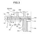
- Fig. 3 shows a state that a flow rate restricting member (pin member) 55 is inserted in the intercommunication path 51.
- the pin member 55 has a first pin 55A fitted in the lower hole 51A at the back side of the intercommunication path 51, and a second pin 55B that is fitted in the insertion hole 51B at the front side of the intercommunication path 51 while abutting against the first pin 55A.
- a screw member 57 having a hexagonal hole is threaded in the screw hole 51C, and one end of the insertion hole 51B is closed by the screw member 57.
- the screw member 57 is fixed by adhesive agent or the like so as to prevent looseness of the screw member 57.
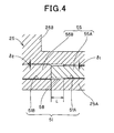
- Fig. 4 is an enlarged view showing the contact portion between the first pin 55A and the second pin 55B.
- the insertion hole 51B constituting the intercommunication path 51 is subjected to finish processing by reaming processing, and the hole diameter of the insertion hole 51B is slightly larger than the lower hole 51A.
- the finishing precision of the inner surface of the insertion hole 51B is high.
- the lower hole 51A is subjected to drill processing, and thus the finishing precision of the inner surface of the insertion hole 51A is low.
- the outer diameter of the first pin 55A is set to be smaller than the inner diameter of the lower hole 51A, and the outer diameter of the second pin 55B is slightly smaller than the inner diameter of the insertion hole 51B.
- the first pin 55A projects to the insertion hole 51B side by the length corresponding to the dimension L. Therefore, oil at the high-pressure side which flows to the left side of Fig. 4 through a gap ⁇ 1 between the lower hole 51A and the first pin 55A enters a pool portion 58 compartmented between the first pin 55A and the insertion hole 51B. Furthermore, the oil in the pool portion 58 passes through a gap ⁇ 2 between the insertion hole 51B and the second pin 55B and further flows to the left side of Fig. 4 , so that the oil is finally sucked through the low-pressure opening 53 ( Fig. 3 ) into the compression chamber 35 at the low-pressure side.
- the intercommunication path 51 is constructed by forming the lower hole 51A having one end opened to the outside of the scroll and then conducting reaming processing on the lower hole 51A from the one end to the position of a predetermined depth H in the lower hole 15A to form the insertion hole 51B. Therefore, the surface roughness of the insertion hole 51B can be reduced (i.e., the inner surface of the insertion hole 51B can be more smoothened), and the gap ⁇ 2 between the inner diameter of the insertion hole 51B and the outer diameter of the second pin 55B inserted in the insertion hole 51B can be remarkably properly managed. Accordingly, the flow rate of the lubricating oil flowing from the high-pressure side to the low-pressure side can be properly regulated (restricted) by exclusively adjusting the gap ⁇ 2 with high precision.
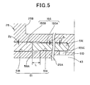
- Fig. 5 shows another embodiment.
- the same elements as shown in Fig. 4 are represented by the same reference numerals, and the description thereof is omitted.
- the pin member 155 is integrally configured. That is, the pin member 155 is constructed by cutting the outer periphery of a first portion 155A at the back side with a second portion 155B at the front side set as a reference. The first portion 155A is fitted in the lower hole 51A at the back side of the intercommunication path 51, and the second portion 155B is fitted in the insertion hole 51B at the front side of the intercommunication path 51. In this construction, the tip portion 155C of the first portion 155A is formed in a conical shape, and the tip portion 155C is fitted to the conical processing trace 51E of the lower portion 51A.
- the number of parts of the pin member 155 can be reduced, and also the assembly of the parts and the exchange of the pin member 155 can be easily performed.
- the substantially conical processing trace 51E of the tip of the drill is left at the end of the back side of the lower hole 51A described above.
- the intercommunication hole 51 and the pin member 155 can be easily set to be coaxial with each other, and the gap ⁇ between the inner diameter of the insertion hole 51B and the outer diameter of the second portion 155B can be properly managed.
- the mechanism of this invention is applied to the inside high-pressure type scroll compressor, however, this mechanism may be applied to an inside low-pressure type scroll compressor.
- the above intercommunication path is disposed at the fixed scroll side, and the flow rate restricting member (pin member) may be inserted in the intercommunication path.
Landscapes
- Engineering & Computer Science (AREA)
- Mechanical Engineering (AREA)
- General Engineering & Computer Science (AREA)
- Rotary Pumps (AREA)
- Applications Or Details Of Rotary Compressors (AREA)
Applications Claiming Priority (1)
| Application Number | Priority Date | Filing Date | Title |
|---|---|---|---|
| JP2009037445A JP5261227B2 (ja) | 2009-02-20 | 2009-02-20 | スクロール型圧縮機 |
Publications (3)
| Publication Number | Publication Date |
|---|---|
| EP2221480A2 true EP2221480A2 (de) | 2010-08-25 |
| EP2221480A3 EP2221480A3 (de) | 2016-10-26 |
| EP2221480B1 EP2221480B1 (de) | 2018-01-31 |
Family
ID=42235724
Family Applications (1)
| Application Number | Title | Priority Date | Filing Date |
|---|---|---|---|
| EP10001731.8A Not-in-force EP2221480B1 (de) | 2009-02-20 | 2010-02-19 | Spiralverdichter |
Country Status (4)
| Country | Link |
|---|---|
| US (1) | US8597004B2 (de) |
| EP (1) | EP2221480B1 (de) |
| JP (1) | JP5261227B2 (de) |
| CN (1) | CN101865133A (de) |
Families Citing this family (5)
| Publication number | Priority date | Publication date | Assignee | Title |
|---|---|---|---|---|
| JP5763358B2 (ja) * | 2011-02-03 | 2015-08-12 | アルバック機工株式会社 | 真空ポンプ |
| KR101810461B1 (ko) * | 2011-03-24 | 2017-12-19 | 엘지전자 주식회사 | 스크롤 압축기 |
| WO2012127752A1 (ja) * | 2011-03-24 | 2012-09-27 | 三洋電機株式会社 | リング体把持治具及びスクロール圧縮装置 |
| KR101480472B1 (ko) * | 2011-09-28 | 2015-01-09 | 엘지전자 주식회사 | 스크롤 압축기 |
| CN107246389A (zh) * | 2017-08-14 | 2017-10-13 | 湖南贝特新能源科技有限公司 | 涡旋压缩机 |
Citations (1)
| Publication number | Priority date | Publication date | Assignee | Title |
|---|---|---|---|---|
| JP2004060532A (ja) | 2002-07-29 | 2004-02-26 | Daikin Ind Ltd | 圧縮機 |
Family Cites Families (25)
| Publication number | Priority date | Publication date | Assignee | Title |
|---|---|---|---|---|
| DE2352965A1 (de) * | 1973-10-23 | 1975-04-30 | Bosch Gmbh Robert | Anordnung zur abgasentgiftung von brennkraftmaschinen |
| JPS5073025U (de) * | 1973-11-06 | 1975-06-26 | ||
| JPS58176486A (ja) | 1982-04-09 | 1983-10-15 | Hitachi Ltd | 密閉形電動圧縮機 |
| JPS60206989A (ja) | 1984-03-30 | 1985-10-18 | Mitsubishi Electric Corp | スクロ−ル形流体機械 |
| JPH01163484A (ja) | 1987-12-19 | 1989-06-27 | Tokico Ltd | 油冷式スクロール圧縮機 |
| JPH01300080A (ja) * | 1988-05-30 | 1989-12-04 | Matsushita Refrig Co Ltd | スクロールコンプレッサ |
| JP2600400B2 (ja) * | 1989-11-02 | 1997-04-16 | 松下電器産業株式会社 | スクロール圧縮機 |
| EP0469700B1 (de) * | 1990-07-31 | 1996-07-24 | Copeland Corporation | Schmiereinrichtung für Spiralmaschine |
| EP0518356B1 (de) | 1991-06-13 | 1995-05-10 | Daikin Industries, Limited | Strömungsmaschine in Spiralbauweise |
| US5511831A (en) | 1993-01-04 | 1996-04-30 | Modine Manufacturing Company | Self-centering, self-seating, double-sealing, interference fit tube joint |
| JPH10196572A (ja) | 1997-01-07 | 1998-07-31 | Matsushita Electric Ind Co Ltd | 密閉型圧縮機 |
| JPH1163484A (ja) | 1997-08-20 | 1999-03-05 | Matsushita Electric Ind Co Ltd | 燃焼制御装置 |
| US6203299B1 (en) * | 1998-12-21 | 2001-03-20 | Scroll Technologies | Capacity modulation for scroll compressors |
| JP3873574B2 (ja) * | 2000-04-27 | 2007-01-24 | 松下電器産業株式会社 | 圧縮機構部品の加工方法 |
| JP2002168183A (ja) * | 2000-12-04 | 2002-06-14 | Matsushita Electric Ind Co Ltd | スクロール圧縮機 |
| JP2003042080A (ja) * | 2001-07-31 | 2003-02-13 | Matsushita Electric Ind Co Ltd | 密閉型スクロール圧縮機 |
| JP3925229B2 (ja) * | 2002-02-14 | 2007-06-06 | 松下電器産業株式会社 | 密閉型スクロール圧縮機およびそれを用いた冷凍サイクルおよび冷凍装置 |
| KR100924895B1 (ko) | 2002-05-24 | 2009-11-02 | 파나소닉 주식회사 | 스크롤 압축기 |
| US6761545B1 (en) * | 2002-12-31 | 2004-07-13 | Scroll Technologies | Scroll compressor with flow restriction and back pressure chamber tap |
| JP3842222B2 (ja) * | 2003-01-21 | 2006-11-08 | 株式会社オティックス | コモンレールの製造方法 |
| JP4727157B2 (ja) | 2004-02-27 | 2011-07-20 | 三菱重工業株式会社 | スクロール型圧縮機 |
| JP4470636B2 (ja) * | 2004-08-04 | 2010-06-02 | ダイキン工業株式会社 | スクロール式流体機械 |
| JP2006307803A (ja) * | 2005-05-02 | 2006-11-09 | Sanden Corp | スクロール圧縮機 |
| SE530058C2 (sv) | 2005-12-23 | 2008-02-19 | Dustcontrol Internat Ab | Rörledningssystem |
| JP2007285304A (ja) * | 2007-08-06 | 2007-11-01 | ▲荒▼田 哲哉 | スクロール流体機械の作動室注油法 |
-
2009
- 2009-02-20 JP JP2009037445A patent/JP5261227B2/ja not_active Expired - Fee Related
-
2010
- 2010-02-12 CN CN201010118447A patent/CN101865133A/zh active Pending
- 2010-02-19 US US12/709,071 patent/US8597004B2/en not_active Expired - Fee Related
- 2010-02-19 EP EP10001731.8A patent/EP2221480B1/de not_active Not-in-force
Patent Citations (1)
| Publication number | Priority date | Publication date | Assignee | Title |
|---|---|---|---|---|
| JP2004060532A (ja) | 2002-07-29 | 2004-02-26 | Daikin Ind Ltd | 圧縮機 |
Also Published As
| Publication number | Publication date |
|---|---|
| US8597004B2 (en) | 2013-12-03 |
| EP2221480B1 (de) | 2018-01-31 |
| CN101865133A (zh) | 2010-10-20 |
| US20100215534A1 (en) | 2010-08-26 |
| JP2010190168A (ja) | 2010-09-02 |
| EP2221480A3 (de) | 2016-10-26 |
| JP5261227B2 (ja) | 2013-08-14 |
Similar Documents
| Publication | Publication Date | Title |
|---|---|---|
| US8585381B2 (en) | Scroll type compressor having an intercommunication path in which a pin member is inserted | |
| JP4666106B2 (ja) | スクリュー圧縮機 | |
| JP5765379B2 (ja) | スクロール圧縮機 | |
| EP2221481B1 (de) | Spiralverdichter | |
| EP2221480B1 (de) | Spiralverdichter | |
| EP2072821A2 (de) | Motorbetriebener Verdichter | |
| CN106523372B (zh) | 涡旋压缩机 | |
| EP2221452B1 (de) | Spiralverdichter | |
| CN104105878A (zh) | 压缩机 | |
| CN102400915A (zh) | 涡旋压缩机 | |
| EP2233743A1 (de) | Schraubenverdichter | |
| CN116057278A (zh) | 涡旋式压缩机 | |
| CN118946724A (zh) | 涡旋式压缩机 | |
| CN114729630B (zh) | 压缩机 | |
| JP2013068093A (ja) | スクリュー圧縮機 | |
| US11493041B2 (en) | Scroll compressor | |
| US20200347845A1 (en) | Scroll compressor | |
| EP2412980A1 (de) | Einzelschraubenverdichter | |
| EP3339647A1 (de) | Verdichter | |
| CN103835946B (zh) | 涡旋式压缩机 | |
| JP2022075840A (ja) | スクリュー圧縮機 | |
| JP4848844B2 (ja) | 電動圧縮機 | |
| JP2021021345A (ja) | スクロール型圧縮機 | |
| JP2002213380A (ja) | 圧縮機の給油構造 | |
| JP2019019682A (ja) | スクリュー圧縮機 |
Legal Events
| Date | Code | Title | Description |
|---|---|---|---|
| PUAI | Public reference made under article 153(3) epc to a published international application that has entered the european phase |
Free format text: ORIGINAL CODE: 0009012 |
|
| 17P | Request for examination filed |
Effective date: 20100219 |
|
| AK | Designated contracting states |
Kind code of ref document: A2 Designated state(s): AT BE BG CH CY CZ DE DK EE ES FI FR GB GR HR HU IE IS IT LI LT LU LV MC MK MT NL NO PL PT RO SE SI SK SM TR |
|
| AX | Request for extension of the european patent |
Extension state: AL BA RS |
|
| PUAL | Search report despatched |
Free format text: ORIGINAL CODE: 0009013 |
|
| AK | Designated contracting states |
Kind code of ref document: A3 Designated state(s): AT BE BG CH CY CZ DE DK EE ES FI FR GB GR HR HU IE IS IT LI LT LU LV MC MK MT NL NO PL PT RO SE SI SK SM TR |
|
| AX | Request for extension of the european patent |
Extension state: AL BA RS |
|
| RIC1 | Information provided on ipc code assigned before grant |
Ipc: F04C 29/02 20060101ALI20160922BHEP Ipc: F04C 18/02 20060101AFI20160922BHEP |
|
| RBV | Designated contracting states (corrected) |
Designated state(s): AT BE BG CH CY CZ DE DK EE ES FI FR GB GR HR HU IE IS IT LI LT LU LV MC MK MT NL NO PL PT RO SE SI SK SM TR |
|
| GRAP | Despatch of communication of intention to grant a patent |
Free format text: ORIGINAL CODE: EPIDOSNIGR1 |
|
| STAA | Information on the status of an ep patent application or granted ep patent |
Free format text: STATUS: GRANT OF PATENT IS INTENDED |
|
| INTG | Intention to grant announced |
Effective date: 20171009 |
|
| GRAS | Grant fee paid |
Free format text: ORIGINAL CODE: EPIDOSNIGR3 |
|
| GRAA | (expected) grant |
Free format text: ORIGINAL CODE: 0009210 |
|
| STAA | Information on the status of an ep patent application or granted ep patent |
Free format text: STATUS: THE PATENT HAS BEEN GRANTED |
|
| AK | Designated contracting states |
Kind code of ref document: B1 Designated state(s): AT BE BG CH CY CZ DE DK EE ES FI FR GB GR HR HU IE IS IT LI LT LU LV MC MK MT NL NO PL PT RO SE SI SK SM TR |
|
| REG | Reference to a national code |
Ref country code: GB Ref legal event code: FG4D Ref country code: CH Ref legal event code: EP |
|
| REG | Reference to a national code |
Ref country code: AT Ref legal event code: REF Ref document number: 967658 Country of ref document: AT Kind code of ref document: T Effective date: 20180215 |
|
| REG | Reference to a national code |
Ref country code: IE Ref legal event code: FG4D |
|
| REG | Reference to a national code |
Ref country code: DE Ref legal event code: R096 Ref document number: 602010048322 Country of ref document: DE |
|
| REG | Reference to a national code |
Ref country code: NL Ref legal event code: MP Effective date: 20180131 |
|
| REG | Reference to a national code |
Ref country code: LT Ref legal event code: MG4D |
|
| REG | Reference to a national code |
Ref country code: AT Ref legal event code: MK05 Ref document number: 967658 Country of ref document: AT Kind code of ref document: T Effective date: 20180131 |
|
| PG25 | Lapsed in a contracting state [announced via postgrant information from national office to epo] |
Ref country code: NO Free format text: LAPSE BECAUSE OF FAILURE TO SUBMIT A TRANSLATION OF THE DESCRIPTION OR TO PAY THE FEE WITHIN THE PRESCRIBED TIME-LIMIT Effective date: 20180430 Ref country code: ES Free format text: LAPSE BECAUSE OF FAILURE TO SUBMIT A TRANSLATION OF THE DESCRIPTION OR TO PAY THE FEE WITHIN THE PRESCRIBED TIME-LIMIT Effective date: 20180131 Ref country code: HR Free format text: LAPSE BECAUSE OF FAILURE TO SUBMIT A TRANSLATION OF THE DESCRIPTION OR TO PAY THE FEE WITHIN THE PRESCRIBED TIME-LIMIT Effective date: 20180131 Ref country code: FI Free format text: LAPSE BECAUSE OF FAILURE TO SUBMIT A TRANSLATION OF THE DESCRIPTION OR TO PAY THE FEE WITHIN THE PRESCRIBED TIME-LIMIT Effective date: 20180131 Ref country code: LT Free format text: LAPSE BECAUSE OF FAILURE TO SUBMIT A TRANSLATION OF THE DESCRIPTION OR TO PAY THE FEE WITHIN THE PRESCRIBED TIME-LIMIT Effective date: 20180131 Ref country code: NL Free format text: LAPSE BECAUSE OF FAILURE TO SUBMIT A TRANSLATION OF THE DESCRIPTION OR TO PAY THE FEE WITHIN THE PRESCRIBED TIME-LIMIT Effective date: 20180131 |
|
| PG25 | Lapsed in a contracting state [announced via postgrant information from national office to epo] |
Ref country code: IS Free format text: LAPSE BECAUSE OF FAILURE TO SUBMIT A TRANSLATION OF THE DESCRIPTION OR TO PAY THE FEE WITHIN THE PRESCRIBED TIME-LIMIT Effective date: 20180531 Ref country code: SE Free format text: LAPSE BECAUSE OF FAILURE TO SUBMIT A TRANSLATION OF THE DESCRIPTION OR TO PAY THE FEE WITHIN THE PRESCRIBED TIME-LIMIT Effective date: 20180131 Ref country code: BG Free format text: LAPSE BECAUSE OF FAILURE TO SUBMIT A TRANSLATION OF THE DESCRIPTION OR TO PAY THE FEE WITHIN THE PRESCRIBED TIME-LIMIT Effective date: 20180430 Ref country code: LV Free format text: LAPSE BECAUSE OF FAILURE TO SUBMIT A TRANSLATION OF THE DESCRIPTION OR TO PAY THE FEE WITHIN THE PRESCRIBED TIME-LIMIT Effective date: 20180131 Ref country code: PL Free format text: LAPSE BECAUSE OF FAILURE TO SUBMIT A TRANSLATION OF THE DESCRIPTION OR TO PAY THE FEE WITHIN THE PRESCRIBED TIME-LIMIT Effective date: 20180131 Ref country code: GR Free format text: LAPSE BECAUSE OF FAILURE TO SUBMIT A TRANSLATION OF THE DESCRIPTION OR TO PAY THE FEE WITHIN THE PRESCRIBED TIME-LIMIT Effective date: 20180501 Ref country code: AT Free format text: LAPSE BECAUSE OF FAILURE TO SUBMIT A TRANSLATION OF THE DESCRIPTION OR TO PAY THE FEE WITHIN THE PRESCRIBED TIME-LIMIT Effective date: 20180131 |
|
| REG | Reference to a national code |
Ref country code: CH Ref legal event code: PL |
|
| PG25 | Lapsed in a contracting state [announced via postgrant information from national office to epo] |
Ref country code: RO Free format text: LAPSE BECAUSE OF FAILURE TO SUBMIT A TRANSLATION OF THE DESCRIPTION OR TO PAY THE FEE WITHIN THE PRESCRIBED TIME-LIMIT Effective date: 20180131 Ref country code: IT Free format text: LAPSE BECAUSE OF FAILURE TO SUBMIT A TRANSLATION OF THE DESCRIPTION OR TO PAY THE FEE WITHIN THE PRESCRIBED TIME-LIMIT Effective date: 20180131 Ref country code: EE Free format text: LAPSE BECAUSE OF FAILURE TO SUBMIT A TRANSLATION OF THE DESCRIPTION OR TO PAY THE FEE WITHIN THE PRESCRIBED TIME-LIMIT Effective date: 20180131 |
|
| REG | Reference to a national code |
Ref country code: DE Ref legal event code: R097 Ref document number: 602010048322 Country of ref document: DE |
|
| REG | Reference to a national code |
Ref country code: BE Ref legal event code: MM Effective date: 20180228 |
|
| PG25 | Lapsed in a contracting state [announced via postgrant information from national office to epo] |
Ref country code: MC Free format text: LAPSE BECAUSE OF FAILURE TO SUBMIT A TRANSLATION OF THE DESCRIPTION OR TO PAY THE FEE WITHIN THE PRESCRIBED TIME-LIMIT Effective date: 20180131 Ref country code: CH Free format text: LAPSE BECAUSE OF NON-PAYMENT OF DUE FEES Effective date: 20180228 Ref country code: LI Free format text: LAPSE BECAUSE OF NON-PAYMENT OF DUE FEES Effective date: 20180228 Ref country code: CZ Free format text: LAPSE BECAUSE OF FAILURE TO SUBMIT A TRANSLATION OF THE DESCRIPTION OR TO PAY THE FEE WITHIN THE PRESCRIBED TIME-LIMIT Effective date: 20180131 Ref country code: SK Free format text: LAPSE BECAUSE OF FAILURE TO SUBMIT A TRANSLATION OF THE DESCRIPTION OR TO PAY THE FEE WITHIN THE PRESCRIBED TIME-LIMIT Effective date: 20180131 Ref country code: SM Free format text: LAPSE BECAUSE OF FAILURE TO SUBMIT A TRANSLATION OF THE DESCRIPTION OR TO PAY THE FEE WITHIN THE PRESCRIBED TIME-LIMIT Effective date: 20180131 Ref country code: LU Free format text: LAPSE BECAUSE OF NON-PAYMENT OF DUE FEES Effective date: 20180219 Ref country code: DK Free format text: LAPSE BECAUSE OF FAILURE TO SUBMIT A TRANSLATION OF THE DESCRIPTION OR TO PAY THE FEE WITHIN THE PRESCRIBED TIME-LIMIT Effective date: 20180131 |
|
| PLBE | No opposition filed within time limit |
Free format text: ORIGINAL CODE: 0009261 |
|
| STAA | Information on the status of an ep patent application or granted ep patent |
Free format text: STATUS: NO OPPOSITION FILED WITHIN TIME LIMIT |
|
| REG | Reference to a national code |
Ref country code: IE Ref legal event code: MM4A |
|
| GBPC | Gb: european patent ceased through non-payment of renewal fee |
Effective date: 20180430 |
|
| 26N | No opposition filed |
Effective date: 20181102 |
|
| PG25 | Lapsed in a contracting state [announced via postgrant information from national office to epo] |
Ref country code: IE Free format text: LAPSE BECAUSE OF NON-PAYMENT OF DUE FEES Effective date: 20180219 |
|
| PG25 | Lapsed in a contracting state [announced via postgrant information from national office to epo] |
Ref country code: GB Free format text: LAPSE BECAUSE OF NON-PAYMENT OF DUE FEES Effective date: 20180430 Ref country code: SI Free format text: LAPSE BECAUSE OF FAILURE TO SUBMIT A TRANSLATION OF THE DESCRIPTION OR TO PAY THE FEE WITHIN THE PRESCRIBED TIME-LIMIT Effective date: 20180131 Ref country code: BE Free format text: LAPSE BECAUSE OF NON-PAYMENT OF DUE FEES Effective date: 20180228 |
|
| PG25 | Lapsed in a contracting state [announced via postgrant information from national office to epo] |
Ref country code: FR Free format text: LAPSE BECAUSE OF NON-PAYMENT OF DUE FEES Effective date: 20180331 |
|
| PGFP | Annual fee paid to national office [announced via postgrant information from national office to epo] |
Ref country code: DE Payment date: 20190219 Year of fee payment: 10 |
|
| PG25 | Lapsed in a contracting state [announced via postgrant information from national office to epo] |
Ref country code: MT Free format text: LAPSE BECAUSE OF NON-PAYMENT OF DUE FEES Effective date: 20180219 |
|
| PG25 | Lapsed in a contracting state [announced via postgrant information from national office to epo] |
Ref country code: TR Free format text: LAPSE BECAUSE OF FAILURE TO SUBMIT A TRANSLATION OF THE DESCRIPTION OR TO PAY THE FEE WITHIN THE PRESCRIBED TIME-LIMIT Effective date: 20180131 |
|
| PG25 | Lapsed in a contracting state [announced via postgrant information from national office to epo] |
Ref country code: HU Free format text: LAPSE BECAUSE OF FAILURE TO SUBMIT A TRANSLATION OF THE DESCRIPTION OR TO PAY THE FEE WITHIN THE PRESCRIBED TIME-LIMIT; INVALID AB INITIO Effective date: 20100219 Ref country code: PT Free format text: LAPSE BECAUSE OF FAILURE TO SUBMIT A TRANSLATION OF THE DESCRIPTION OR TO PAY THE FEE WITHIN THE PRESCRIBED TIME-LIMIT Effective date: 20180131 |
|
| PG25 | Lapsed in a contracting state [announced via postgrant information from national office to epo] |
Ref country code: CY Free format text: LAPSE BECAUSE OF FAILURE TO SUBMIT A TRANSLATION OF THE DESCRIPTION OR TO PAY THE FEE WITHIN THE PRESCRIBED TIME-LIMIT Effective date: 20180131 Ref country code: MK Free format text: LAPSE BECAUSE OF NON-PAYMENT OF DUE FEES Effective date: 20180131 |
|
| REG | Reference to a national code |
Ref country code: DE Ref legal event code: R119 Ref document number: 602010048322 Country of ref document: DE |
|
| PG25 | Lapsed in a contracting state [announced via postgrant information from national office to epo] |
Ref country code: DE Free format text: LAPSE BECAUSE OF NON-PAYMENT OF DUE FEES Effective date: 20200901 |