EP2218852A2 - Antriebseinheit für einen Treibstangenbeschlag - Google Patents
Antriebseinheit für einen Treibstangenbeschlag Download PDFInfo
- Publication number
- EP2218852A2 EP2218852A2 EP10150729A EP10150729A EP2218852A2 EP 2218852 A2 EP2218852 A2 EP 2218852A2 EP 10150729 A EP10150729 A EP 10150729A EP 10150729 A EP10150729 A EP 10150729A EP 2218852 A2 EP2218852 A2 EP 2218852A2
- Authority
- EP
- European Patent Office
- Prior art keywords
- housing
- drive unit
- housing walls
- unit according
- sheet metal
- Prior art date
- Legal status (The legal status is an assumption and is not a legal conclusion. Google has not performed a legal analysis and makes no representation as to the accuracy of the status listed.)
- Granted
Links
- 239000002184 metal Substances 0.000 claims abstract description 27
- 238000005452 bending Methods 0.000 description 7
- 238000004519 manufacturing process Methods 0.000 description 4
- 238000000034 method Methods 0.000 description 4
- 238000005266 casting Methods 0.000 description 1
- 238000006073 displacement reaction Methods 0.000 description 1
- 238000009434 installation Methods 0.000 description 1
- 230000002452 interceptive effect Effects 0.000 description 1
- 238000004080 punching Methods 0.000 description 1
- 125000006850 spacer group Chemical group 0.000 description 1
- 210000000689 upper leg Anatomy 0.000 description 1
Images

Classifications
-
- E—FIXED CONSTRUCTIONS
- E05—LOCKS; KEYS; WINDOW OR DOOR FITTINGS; SAFES
- E05C—BOLTS OR FASTENING DEVICES FOR WINGS, SPECIALLY FOR DOORS OR WINDOWS
- E05C9/00—Arrangements of simultaneously actuated bolts or other securing devices at well-separated positions on the same wing
- E05C9/02—Arrangements of simultaneously actuated bolts or other securing devices at well-separated positions on the same wing with one sliding bar for fastening when moved in one direction and unfastening when moved in opposite direction; with two sliding bars moved in the same direction when fastening or unfastening
- E05C9/021—Arrangements of simultaneously actuated bolts or other securing devices at well-separated positions on the same wing with one sliding bar for fastening when moved in one direction and unfastening when moved in opposite direction; with two sliding bars moved in the same direction when fastening or unfastening with rack and pinion mechanism
Definitions
- the invention relates to a drive unit for an espagnolette fitting of a window, a French window or the like with a housing housing having two housing walls, with a drive pinion rotatably mounted between the housing walls, with a longitudinally displaceable guided by the drive pinion drive rod section and with a drive rod portion at least partially covering Stulpschienenabites ,
- Such a drive unit is for example from the EP 0 113 664 B1 known.
- the housing walls are each made with one half of a cover of Stulpschienenabitess as castings and the same structure.
- the housing and the cover of the faceplate section can be composed of two equal parts.
- the housing engages with the cover the Stulpschienenabêt and leads the underlying drive rod section.
- a disadvantage of this drive unit is that the cover extends beyond the face-plate in the state mounted on the window and that it is expensive to manufacture because of the high number of components.
- a drive unit has become known in which the housing is made of a drive pinion cross-plate bending part.
- the two housing walls of the bent sheet metal part are made in one piece and have projections on their side facing the cuff rail section, with which they penetrate in recesses of the cuff rail section.
- the projections of the housing walls are fixed in the faceplate section.
- a disadvantage of this drive unit is the large number of expensive to install components.
- in the assembled state of the drive unit can withstand interfering edges of the housing walls above the Stulpschienenabêt.
- the invention is based on the problem of further developing a drive unit of the type mentioned at the beginning in such a way that it has a particularly small number of components and avoids disturbing protruding covers, edges or tabs over the cuff rail section.
- the number of components to be mounted is kept particularly low, since a separate mounting of the cuff rail section on the housing walls according to the invention is not required.
- the number of components of the drive unit according to the invention is therefore particularly low.
- protruding edges, covers or tabs of the housing walls are avoided by the one-piece design over the cuff rail section.
- the one-piece production of Stulpschienenabitess with the housing walls designed according to another advantageous embodiment of the invention is particularly simple if the housing is made as a U-shaped bent sheet metal part, the Stulpschienenabrough a base of the sheet metal part and the housing walls projecting from the base of the sheet metal part Forming thighs.
- the housing walls are simply produced by bending the Stulpschienenabitess.
- the production of the housing walls with the Stulpschienenabêt can be done in the punching and bending process of a single piece of sheet metal.
- Bending of the housing can be easily avoided in accordance with another advantageous embodiment of the invention, when the housing walls have a connection on a remote from the Stulpschienenabrough area.
- the housing is structurally particularly simple according to another advantageous embodiment of the invention, when the connection of the housing walls has a screw or riveting.
- connection of the housing walls has at least one of the housing walls angled, connected to the opposite housing wall sheet metal strip.
- the metal strip also facilitates the limitation of the distance of the housing walls from each other.
- the housing has according to another advantageous embodiment of the invention on smooth outer sides of the housing walls, when the housing walls each have one another to angled sheet metal strips and when the metal strips are connected together at their free ends.
- the free ends of the metal strips could, for example, be welded together.
- it contributes according to another advantageous embodiment of the invention, when the connection of the free ends of the metal strips is designed form-fitting. This also ensures a particularly high dimensional accuracy of the housing.
- the positive connection of the free ends of the metal strips is preferably produced by means of a dovetail guide.
- the structural complexity for the exact positioning of the drive pinion in the housing can be kept particularly low according to another advantageous embodiment of the invention, if at least one bearing collar for the drive pinion is integrally formed on the housing walls. This design also facilitates the assembly of the drive pinion and the drive rod portion in the housing.
- the drive unit according to the invention can be made particularly easily automated.
- the drive unit according to the invention is screwed into the window by passing screws transversely through the housing.
- the housing has fferbohronne for this purpose.
- a deformation of the housing can be according to another advantageous embodiment of the invention reliably avoid when screwing in the window when the housing walls of pipe sections are kept at a distance and when the pipe sections have fferbohrept the housing.
- the pipe pieces also serve the riveting of the housing walls.
- the number of parts can be further reduced by another advantageous development of the invention, when the screw holes of the housing are formed by a sleeve-shaped extension on the housing walls.
- FIG. 1 shows in perspective a drive unit for driving an espagnolette, not shown, a window, a French window or the like with a rotatably mounted in a housing 1 drive pinion 2 and a longitudinally displaceable espagnolette section 3.
- the housing 1 has two housing walls 4, 5 and the espagnolette section 3 partially overlapping Stulpschienenabites 6.
- the housing walls 4, 5 are thus made in one piece with the Stulpschienenab mustard 6.
- the housing walls 4, 5 are also secured by means of two positive connections 7, 8 against bending.
- the drive pinion 2 has a square socket 9 for rotatably receiving a handle, not shown, of the espagnolette fitting and drives the drive rod section 3 at a rotation.
- the plastic fuse 10 thus serves as a central fixing of the drive unit and is sheared off during a displacement of the drive rod section 3 by a rotation of the drive pinion 2.
- the drive rod section 3 has connections 11, 12 for connection to further drive rod sections, not shown. Alternatively, closures of the espagnolette fitting can also be connected directly to the illustrated drive rod section 3.
- FIG. 2 shows a sectional view through the drive unit FIG. 1 along the line II - II. It can be seen that the housing walls 4, 5 each have a bearing collar 13, 14 for supporting the drive pinion 2. The drive pinion 2 meshes with external teeth 15 a series of recesses in the drive rod section 3. The cuff rail section 6 forms a guide for the drive rod section 3.
- FIG. 3 shows in a sectional view through the housing 1 of the drive unit FIG. 1 one of the connections 7 of the housing walls 4, 5. It can be seen that the connection 7 on the housing walls 4, 5 integrally formed sheet metal strips 16, 17 has.
- the metal strips 16, 17 are angled towards each other and positively connected by means arranged in the form of a dovetail guide form-locking surfaces.
- the housing walls 4, 5 with the metal strips 16, 17, the bearing collars 13, 14 and the Stulpschienenabêt 6 are made in one piece from a flat sheet metal part in the stamping, deep drawing and bending process.
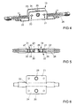
- FIG. 4 shows a further embodiment of the drive unit, in which in a housing 19 fferbohritch 20, 21 are arranged.
- the housing 19 also has two housing walls 23, 24 made in one piece with a cuff rail section 22. Between the housing walls 23, 24, a drive pinion 25 is also rotatably mounted for driving a drive rod section 26 guided in a longitudinally displaceable manner.
- FIG. 5 shows a sectional view of the drive unit FIG. 4 along the line V - V.
- the housing walls 23, 24 are held by pipe sections 27, 28 at a distance.
- the pipe sections 27, 28 also serve for riveting with the housing walls 23, 24 and have the fferbohrept 20, 21 on.
- the pipe sections 27, 29 thus form connections 31, 32 of the housing walls 23, 24 which are remote from the cuff rail section 22.
- the housing walls 23, 24 are produced in one piece with bearing collars 29, 30 for supporting the drive pinion 25.
- the screw holes 20, 21 can also be formed by a sleeve-shaped extension on the housing walls 23, 24.
- FIG. 6 shows the housing 19 of the drive unit FIG. 4 with the housing walls 23, 24 and the Stulpschienenabrough 22 as a flat sheet metal part.
- This sheet metal part can be prefabricated in the stamping process and provided in the deep drawing process with the bearing collars 29, 30.
- the housing walls 23, 24 angled from the faceplate section 22 and so the in FIG. 4 shown housing 19 manufactured.
Landscapes
- Engineering & Computer Science (AREA)
- Mechanical Engineering (AREA)
- Power-Operated Mechanisms For Wings (AREA)
- Transmission Devices (AREA)
- Window Of Vehicle (AREA)
Abstract
Description
- Die Erfindung betrifft eine Antriebseinheit für einen Treibstangenbeschlag eines Fensters, einer Fenstertür oder dergleichen mit einem zwei Gehäusewände aufweisenden Gehäuse, mit einem zwischen den Gehäusewänden drehbar gelagerten Antriebsritzel, mit einem längsverschieblich geführten, von dem Antriebsritzel antreibbaren Treibstangenabschnitt und mit einem den Treibstangenabschnitt zumindest teilweise überdeckenden Stulpschienenabschnitt.
- Eine solche Antriebseinheit ist beispielsweise aus der
EP 0 113 664 B1 bekannt. Bei dieser Antriebseinheit sind die Gehäusewände jeweils mit einer Hälfte einer Abdeckung des Stulpschienenabschnitts als Gussteile gefertigt und gleich aufgebaut. Damit lässt sich das Gehäuse und die Abdeckung des Stulpschienenabschnitts aus zwei gleichen Teilen zusammensetzen. Das Gehäuse übergreift mit der Abdeckung den Stulpschienenabschnitt und führt den darunter liegenden Treibstangenabschnitt. Nachteilig bei dieser Antriebseinheit ist jedoch, dass die Abdeckung die Stulpschiene im am Fenster montierten Zustand überragt und dass sie wegen der hohen Anzahl von Bauteilen aufwändig zu fertigen ist. - Aus der
DE 660 74 69 U ist eine Antriebseinheit bekannt geworden, bei der das Gehäuse aus einem das Antriebsritzel übergreifenden Blechbiegeteil gefertigt ist. Die beiden Gehäusewände des Blechbiegeteils sind einstückig gefertigt und weisen an ihrer auf den Stulpschienenabschnitt zugewandten Seite jeweils Vorsprünge auf, mit denen sie in Ausnehmungen des Stulpschienenabschnitts eindringen. Die Vorsprünge der Gehäusewände sind in dem Stulpschienenabschnitt befestigt. Nachteilig bei dieser Antriebseinheit ist die große Anzahl von aufwändig zu montierenden Bauteilen. Zudem können im montierten Zustand der Antriebseinheit störende Kanten der Gehäusewände über dem Stulpschienenabschnitt überstehen. - Aus der
EP 1 863 990 B1 ist ebenfalls eine solche Antriebseinheit bekannt geworden, bei der zwei gleiche, aus Blech gefertigte Gehäusewände von einem Distanzstück auf Abstand gehalten werden. Die Gehäusewände weisen Laschen zum Umgreifen des Stulpschienenabschnitts auf. Im montierten Zustand stehen die Laschen über dem Stulpschienenabschnitt über. Damit weist diese Antriebseinheit ebenfalls eine hohe Anzahl an Bauteilen auf. - Der Erfindung liegt das Problem zugrunde, eine Antriebseinheit der eingangs genannten Art so weiter zu bilden, dass sie eine besonders geringe Anzahl an Bauteilen aufweist und über dem Stulpschienenabschnitt störend überstehende Abdeckungen, Kanten oder Laschen vermeidet.
- Dieses Problem wird erfindungsgemäß dadurch gelöst, dass der Stulpschienenabschnitt einstückig mit den beiden Gehäusewänden gefertigt ist.
- Durch diese Gestaltung wird die Anzahl der zu montierenden Bauteile besonders gering gehalten, da eine separate Montage des Stulpschienenabschnitts an den Gehäusewänden erfindungsgemäß nicht erforderlich ist. Die Anzahl der Bauteile der erfindungsgemäßen Antriebseinheit ist daher besonders gering. Weiterhin werden durch die einstückige Gestaltung über dem Stulpschienenabschnitt überstehende Kanten, Abdeckungen oder Laschen der Gehäusewände vermieden.
- Die einstückige Fertigung des Stulpschienenabschnitts mit den Gehäusewänden gestaltet sich gemäß einer anderen vorteilhaften Weiterbildung der Erfindung besonders einfach, wenn das Gehäuse als im Querschnitt U-förmig gebogenes Blechteil gefertigt ist, wobei der Stulpschienenabschnitt eine Basis des Blechteils und die Gehäusewände von der Basis des Blechteils abstehende Schenkel bilden. Hierdurch werden die Gehäusewände einfach durch Abwinklungen des Stulpschienenabschnitts erzeugt. Die Fertigung der Gehäusewände mit dem Stulpschienenabschnitt kann im Stanz- und Biegeverfahren aus einem einzelnen Blechstück erfolgen. Ein weiterer Vorteil dieser Gestaltung besteht darin, dass der Stulpschienenabschnitt, und damit der nach der Montage sichtbare Abschnitt der erfindungsgemäßen Antriebseinheit eine glatte Oberfläche aufweist, da keine Verbindungen oder Nähte auf dem Stulpschienenabschnitt und an den angrenzenden Gehäusewänden vorhanden sind.
- Ein Aufbiegen des Gehäuses lässt sich gemäß einer anderen vorteilhaften Weiterbildung der Erfindung einfach vermeiden, wenn die Gehäusewände an einem von dem Stulpschienenabschnitt entfernten Bereich eine Verbindung aufweisen.
- Das Gehäuse gestaltet sich gemäß einer anderen vorteilhaften Weiterbildung der Erfindung konstruktiv besonders einfach, wenn die Verbindung der Gehäusewände eine Verschraubung oder Vernietung aufweist.
- Zur Vereinfachung der Montage des Gehäuses trägt es gemäß einer anderen vorteilhaften Weiterbildung der Erfindung bei, wenn die Verbindung der Gehäusewände zumindest einen von einem der Gehäusewände abgewinkelten, mit der gegenüberliegenden Gehäusewand verbundenen Blechstreifen aufweist. Der Blechstreifen erleichtert zudem die Begrenzung des Abstandes der Gehäusewände voneinander.
- Das Gehäuse weist gemäß einer anderen vorteilhaften Weiterbildung der Erfindung glatte Außenseiten der Gehäusewände auf, wenn die Gehäusewände jeweils aufeinander zu abgewinkelte Blechstreifen aufweisen und wenn die Blechstreifen an ihren freien Enden miteinander verbunden sind.
- Die freien Enden der Blechstreifen könnten beispielsweise miteinander verschweißt sein. Zur Vereinfachung der Montage des Gehäuses trägt es jedoch gemäß einer anderen vorteilhaften Weiterbildung der Erfindung bei, wenn die Verbindung der freien Enden der Blechstreifen formschlüssig gestaltet ist. Hierdurch lässt sich zudem eine besonders hohe Maßgenauigkeit des Gehäuses sicherstellen. Die formschlüssige Verbindung der freien Enden der Blechstreifen wird vorzugsweise mittels einer Schwalbenschwanzführung erzeugt.
- Der bauliche Aufwand zur genauen Positionierung des Antriebsritzels in dem Gehäuse lässt sich gemäß einer anderen vorteilhaften Weiterbildung der Erfindung besonders gering halten, wenn zumindest ein Lagerbund für das Antriebsritzel an den Gehäusewänden angeformt ist. Diese Gestaltung erleichtert zudem die Montage des Antriebsritzels und des Treibstangenabschnitts in dem Gehäuse. Die erfindungsgemäße Antriebseinheit kann hierdurch besonders einfach automatisiert gefertigt werden.
- In der Regel wird die erfindungsgemäße Antriebseinheit in dem Fenster verschraubt, indem Schrauben quer durch das Gehäuse hindurch geführt werden. Das Gehäuse hat hierfür Schraubbohrungen. Eine Verformung des Gehäuses lässt sich gemäß einer anderen vorteilhaften Weiterbildung der Erfindung bei der Verschraubung im Fenster zuverlässig vermeiden, wenn die Gehäusewände von Rohrstücken auf Abstand gehalten sind und wenn die Rohrstücke Schraubbohrungen des Gehäuses aufweisen. Vorzugsweise dienen die Rohrstücke zugleich der Vernietung der Gehäusewände.
- Die Teileanzahl kann durch eine andere vorteilhafte Weiterentwicklung der Erfindung weiter reduziert werden, wenn die Schraubbohrungen des Gehäuses durch einen hülsenförmigen Fortsatz an den Gehäusewänden angeformt sind.
- Die Erfindung lässt zahlreiche Ausführungsformen zu. Zur weiteren Verdeutlichung ihres Grundprinzips sind zwei davon in der Zeichnung dargestellt und werden nachfolgend beschrieben. Diese zeigt in
- Fig. 1
- perspektivisch eine erfindungsgemäße Antriebseinheit,
- Fig. 2
- eine Schnittdarstellung durch die Antriebseinheit aus
Figur 1 entlang der Linie II - II, - Fig. 3
- eine Schnittdarstellung durch ein Gehäuse der Antriebseinheit aus
Figur 1 , - Fig. 4
- perspektivisch eine weitere Aufführungsform der erfindungsgemäßen Antriebseinheit,
- Fig. 5
- eine Schnittdarstellung durch die Antriebseinheit aus
Figur 4 entlang der Linie V - V, - Fig. 6
- ein Gehäuse der Antriebseinheit aus
Figur 4 während der Fertigung. -
Figur 1 zeigt perspektivisch eine Antriebseinheit zum Antrieb eines nicht dargestellten Treibstangenbeschlages eines Fensters, einer Fenstertür oder dergleichen mit einem in einem Gehäuse 1 drehbar gelagerten Antriebsritzel 2 und einem längsverschieblich geführten Treibstangenabschnitt 3. Das Gehäuse 1 hat zwei Gehäusewände 4, 5 und einen den Treibstangenabschnitt 3 teilweise überdeckenden Stulpschienenabschnitt 6. Die Gehäusewände 4, 5 sind damit einstückig mit dem Stulpschienenabschnitt 6 gefertigt. Die Gehäusewände 4, 5 sind zudem mittels zweier formschlüssiger Verbindungen 7, 8 gegen ein Aufbiegen gesichert. Das Antriebsritzel 2 hat einen Innenvierkant 9 zur drehfesten Aufnahme einer nicht dargestellten Handhabe des Treibstangenbeschlages und treibt bei einer Drehung den Treibstangenabschnitt 3 an. In der dargestellten mittleren Stellung ist der Treibstangenabschnitt 3 über eine Kunststoffsicherung 10 mit dem Stulpschienenabschnitt 6 verbunden. Die Kunststoffsicherung 10 dient damit als Mittenfixierung der Antriebseinheit und wird bei einer Verschiebung des Treibstangenabschnitts 3 durch eine Drehung des Antriebsritzels 2 abgeschert. Der Treibstangenabschnitt 3 weist Anschlüsse 11, 12 zur Verbindung mit weiteren, nicht dargestellten Treibstangenabschnitten auf. Alternativ dazu können Verschlüsse des Treibstangenbeschlages auch unmittelbar mit dem dargestellten Treibstangenabschnitt 3 verbunden werden. -
Figur 2 zeigt eine Schnittdarstellung durch die Antriebseinheit ausFigur 1 entlang der Linie II - II. Hierbei ist zu erkennen, dass die Gehäusewände 4, 5 jeweils einen Lagerbund 13, 14 zur Lagerung des Antriebsritzels 2 aufweisen. Das Antriebsritzel 2 kämmt mit einer Außenverzahnung 15 eine Reihe von Ausnehmungen in dem Treibstangenabschnitt 3. Der Stulpschienenabschnitt 6 bildet eine Führung für den Treibstangenabschnitt 3. -
Figur 3 zeigt in einer Schnittdarstellung durch das Gehäuse 1 der Antriebseinheit ausFigur 1 eine der Verbindungen 7 der Gehäusewände 4, 5. Hierbei ist zu erkennen, dass die Verbindung 7 an den Gehäusewänden 4, 5 angeformte Blechstreifen 16, 17 aufweist. Die Blechstreifen 16, 17 sind aufeinander zu abgewinkelt und mittels in Form einer Schwalbenschwanzführung angeordneter Formschlussflächen formschlüssig miteinander verbunden. Die Gehäusewände 4, 5 mit den Blechstreifen 16, 17, die Lagerbunde 13, 14 und der Stulpschienenabschnitt 6 sind einstückig aus einem ebenen Blechteil im Stanz-, Tiefzieh- und Biegeverfahren gefertigt. -
Figur 4 zeigt eine weitere Ausführungsform der Antriebseinheit, bei der in einem Gehäuse 19 Schraubbohrungen 20, 21 angeordnet sind. Das Gehäuse 19 hat zudem zwei einstückig mit einem Stulpschienenabschnitt 22 gefertigte Gehäusewände 23, 24. Zwischen den Gehäusewänden 23, 24 ist zudem ein Antriebsritzel 25 zum Antrieb eines längsverschieblich geführten Treibstangenabschnitts 26 drehbar gelagert. -
Figur 5 zeigt eine Schnittdarstellung der Antriebseinheit ausFigur 4 entlang der Linie V - V. Die Gehäusewände 23, 24 werden von Rohrstücken 27, 28 auf Abstand gehalten. Die Rohrstücke 27, 28 dienen zudem zur Vernietung mit den Gehäusewänden 23, 24 und weisen die Schraubbohrungen 20, 21 auf. Die Rohrstücke 27, 29 bilden damit von dem Stulpschienenabschnitt 22 entfernte Verbindungen 31, 32 der Gehäusewände 23, 24. Weiterhin sind die Gehäusewände 23, 24 einstückig mit Lagerbunden 29, 30 zur Lagerung des Antriebsritzels 25 gefertigt. Die Schraubbohrungen 20, 21 können auch durch einen hülsenförmigen Fortsatz an den Gehäusewänden 23, 24 angeformt werden. -
Figur 6 zeigt das Gehäuse 19 der Antriebseinheit ausFigur 4 mit den Gehäusewänden 23, 24 und dem Stulpschienenabschnitt 22 als ebenes Blechteil. Dieses Blechteil lässt sich im Stanzverfahren vorfertigen und im Tiefziehverfahren mit den Lagerbunden 29, 30 versehen. Entlang strichpunktiert dargestellter Biegelinien werden die Gehäusewände 23, 24 von dem Stulpschienenabschnitt 22 abgewinkelt und so das inFigur 4 dargestellte Gehäuse 19 gefertigt.
Claims (10)
- Antriebseinheit für einen Treibstangenbeschlag eines Fensters, einer Fenstertür oder dergleichen mit einem zwei Gehäusewände (4, 5, 23, 24) aufweisenden Gehäuse (1, 19), mit einem zwischen den Gehäusewänden (4, 5, 23, 24) drehbar gelagerten Antriebsritzel (2, 25), mit einem längsverschieblich geführten, von dem Antriebsritzel (2, 25) antreibbaren Treibstangenabschnitt (3, 26) und mit einem den Treibstangenabschnitt (3, 26) zumindest teilweise überdeckenden Stulpschienenabschnitt (6, 22), dadurch gekennzeichnet, dass der Stulpschienenabschnitt (6, 22) einstückig mit den beiden Gehäusewänden (4, 5, 23, 24) gefertigt ist.
- Antriebseinheit nach Anspruch 1, dadurch gekennzeichnet, dass das Gehäuse (1, 19) als im Querschnitt U-förmig gebogenes Blechteil gefertigt ist, wobei der Stulpschienenabschnitt (6, 22) eine Basis des Blechteils und die Gehäusewände (4, 5, 23, 24) von der Basis des Blechteils abstehende Schenkel bilden.
- Antriebseinheit nach Anspruch 1 oder 2, dadurch gekennzeichnet, dass die Gehäusewände (4, 5, 23, 24) an einem von dem Stulpschienenabschnitt (6, 22) entfernten Bereich eine Verbindung (7, 8, 31, 32) aufweisen.
- Antriebseinheit nach Anspruch 3, dadurch gekennzeichnet, dass die Verbindung (31, 32) der Gehäusewände (23, 24) eine Verschraubung oder Vernietung aufweist.
- Antriebseinheit nach Anspruch 3 oder 4, dadurch gekennzeichnet, dass die Verbindung (7, 8) der Gehäusewände (4, 5) zumindest einen von einem der Gehäusewände (4, 5) abgewinkelten, mit der gegenüberliegenden Gehäusewand (5, 4) verbundenen Blechstreifen (16, 17) aufweist.
- Antriebseinheit nach Anspruch 5, dadurch gekennzeichnet, dass die Gehäusewände (4, 5) jeweils aufeinander zu abgewinkelte Blechstreifen (16, 17) aufweisen und dass die Blechstreifen (16, 17) an ihren freien Enden miteinander verbunden sind.
- Antriebseinheit nach einem der Ansprüche 3 bis 6, dadurch gekennzeichnet, dass die Verbindung (7, 8, 31, 32) der freien Enden der Blechstreifen (4, 5, 23, 24) formschlüssig gestaltet ist.
- Antriebseinheit nach einem der vorhergehenden Ansprüche, dadurch gekennzeichnet, dass zumindest ein Lagerbund (13, 14, 29, 30) für das Antriebsritzel (2, 25) an den Gehäusewänden (4, 5, 23, 24) angeformt ist.
- Antriebseinheit nach einem der vorhergehenden Ansprüche, dadurch gekennzeichnet, dass die Gehäusewände (4, 5, 23, 24) von Rohrstücken (27, 28) auf Abstand gehalten sind und dass die Rohrstücke, (27, 28) Schraubbohrungen (20, 21) des Gehäuses (19) aufweisen.
- Antriebseinheit nach einem der vorhergehenden Ansprüche, dadurch gekennzeichnet, dass die Schraubbohrungen (20, 21) des Gehäuses (19) durch einen hülsenförmigen Fortsatz an den Gehäusewänden (4, 5, 23, 24) angeformt sind.
Applications Claiming Priority (1)
| Application Number | Priority Date | Filing Date | Title |
|---|---|---|---|
| DE102009000822A DE102009000822A1 (de) | 2009-02-12 | 2009-02-12 | Antriebseinheit für einen Treibstangenbeschlag |
Publications (3)
| Publication Number | Publication Date |
|---|---|
| EP2218852A2 true EP2218852A2 (de) | 2010-08-18 |
| EP2218852A3 EP2218852A3 (de) | 2011-09-14 |
| EP2218852B1 EP2218852B1 (de) | 2014-05-07 |
Family
ID=42100891
Family Applications (1)
| Application Number | Title | Priority Date | Filing Date |
|---|---|---|---|
| EP20100150729 Not-in-force EP2218852B1 (de) | 2009-02-12 | 2010-01-14 | Antriebseinheit für einen Treibstangenbeschlag |
Country Status (2)
| Country | Link |
|---|---|
| EP (1) | EP2218852B1 (de) |
| DE (1) | DE102009000822A1 (de) |
Cited By (1)
| Publication number | Priority date | Publication date | Assignee | Title |
|---|---|---|---|---|
| GB2582888A (en) * | 2018-11-29 | 2020-10-14 | Era Home Security Ltd | Espagnolette Lock |
Citations (3)
| Publication number | Priority date | Publication date | Assignee | Title |
|---|---|---|---|---|
| DE6607469U (de) | 1968-05-16 | 1971-03-18 | Frank Gmbh Wilh | Zapfengetriebe |
| EP0113664B1 (de) | 1983-01-07 | 1986-10-29 | Aug. Winkhaus GmbH & Co. KG | Kantengetriebeeinheit |
| EP1863990B1 (de) | 2005-03-29 | 2008-07-09 | Siegenia-Aubi Kg | Treibstangenantrieb |
Family Cites Families (9)
| Publication number | Priority date | Publication date | Assignee | Title |
|---|---|---|---|---|
| DE2344971B2 (de) * | 1973-09-06 | 1980-05-08 | Siegenia-Frank Kg, 5900 Siegen | Treibstangenbeschlag für Fenster, Türen o.dgl |
| DE7603047U1 (de) * | 1976-02-04 | 1976-06-03 | Siegenia-Frank Kg, 5900 Siegen- Kaan-Marienborn | Ueberlappungsverbindung zwischen stulpschienen von treibstangenbeschlaegen |
| DE3836177C2 (de) * | 1988-10-24 | 1996-05-09 | Fliether Karl Gmbh & Co | Vorrichtung zum Verwerfungen ausgleichenden Heranziehen von Türen oder Fenstern |
| DE9212950U1 (de) * | 1992-09-25 | 1992-12-03 | Siegenia-Frank Kg, 5900 Siegen | Treibstangenbeschlag für Fenster, Türen o.dgl. |
| DE19711770C2 (de) * | 1997-03-21 | 1999-03-11 | Roto Frank Ag | Mechanische Überlappungsverbindung |
| DE20100326U1 (de) * | 2001-01-09 | 2001-03-29 | Aug. Winkhaus GmbH & Co. KG., 48291 Telgte | Kantengetriebe für einen Treibstangenbeschlag |
| DE10134249A1 (de) * | 2001-07-18 | 2003-01-30 | Roto Frank Ag | Verriegelungsbeschlag mit drehbarer Riegelleiste |
| DE10354185B4 (de) * | 2003-11-20 | 2015-04-02 | Aug. Winkhaus Gmbh & Co. Kg | Kantengetriebe |
| DE102006000327A1 (de) * | 2006-07-10 | 2008-01-24 | Aug. Winkhaus Gmbh & Co. Kg | Verschluss für einen Treibstangenbeschlag eines Fensters |
-
2009
- 2009-02-12 DE DE102009000822A patent/DE102009000822A1/de not_active Withdrawn
-
2010
- 2010-01-14 EP EP20100150729 patent/EP2218852B1/de not_active Not-in-force
Patent Citations (3)
| Publication number | Priority date | Publication date | Assignee | Title |
|---|---|---|---|---|
| DE6607469U (de) | 1968-05-16 | 1971-03-18 | Frank Gmbh Wilh | Zapfengetriebe |
| EP0113664B1 (de) | 1983-01-07 | 1986-10-29 | Aug. Winkhaus GmbH & Co. KG | Kantengetriebeeinheit |
| EP1863990B1 (de) | 2005-03-29 | 2008-07-09 | Siegenia-Aubi Kg | Treibstangenantrieb |
Cited By (2)
| Publication number | Priority date | Publication date | Assignee | Title |
|---|---|---|---|---|
| GB2582888A (en) * | 2018-11-29 | 2020-10-14 | Era Home Security Ltd | Espagnolette Lock |
| GB2582888B (en) * | 2018-11-29 | 2023-04-26 | Era Home Security Ltd | Espagnolette Lock |
Also Published As
| Publication number | Publication date |
|---|---|
| EP2218852B1 (de) | 2014-05-07 |
| EP2218852A3 (de) | 2011-09-14 |
| DE102009000822A1 (de) | 2010-08-19 |
Similar Documents
| Publication | Publication Date | Title |
|---|---|---|
| WO2009062698A1 (de) | Türantrieb mit einer antriebseinheit | |
| DE102008048711A1 (de) | Drehfalle mit Konturplatten | |
| EP3450811B1 (de) | Schelle | |
| EP2379916B1 (de) | Schaltgabel | |
| EP2218852B1 (de) | Antriebseinheit für einen Treibstangenbeschlag | |
| DE202014100779U1 (de) | Betätigungsvorrichtung für eine Feststellbremse | |
| EP0598927B1 (de) | Betätigungsgetriebe für Beschläge an Fenstern, Türen oder dergleichen | |
| DE202016105919U1 (de) | Gehäuse eines Getriebes, Treibstangenvorrichtung und Anordnung mit einem Gehäuse und einer Treibstangenvorrichtung | |
| AT406700B (de) | Tür, insbesondere brandschutztür | |
| DE102007053340A1 (de) | Eckumlenkung für ein Treibstangenbeschlagsystem für einen Fenster- oder Türflügel | |
| EP0571839B1 (de) | Kupplungsvorrichtung für aneinanderstossende Stulpschienen- und Treibstangenabschnitte und Verfahren zur Fertigstellung einer derartigen Kupplungsvorrichtung | |
| EP1775416B1 (de) | Befestigungssystem für einen Aufsatzrollladenkasten | |
| EP2863000B1 (de) | Aufschiebesicherungsanordnung | |
| DE2609730B2 (de) | Übertragungsvorrichtung für Zug- und Druckkräfte | |
| EP2754803A2 (de) | Riegelstangenbeschlag für ein Fenster oder eine Tür | |
| EP2532813B1 (de) | Zahnstange | |
| EP3224435B1 (de) | Längenverstellbare verbindung für ein gestänge | |
| DE1031177B (de) | Fenstergetriebe mit zwei in einem Getriebegehaeuse gegenlaeufig verschiebbaren Stangen | |
| DE102015104509B3 (de) | Vorrichtung zum Verbinden von Zaunmatten | |
| EP2302297B1 (de) | Leuchtengehäuse | |
| EP3162994A1 (de) | Antriebsgetriebe für einen treibstangenbeschlag | |
| EP2543803B1 (de) | Treibstange für einen Treibstangenbeschlag | |
| EP2801684A1 (de) | Getriebe-Baukastensystem | |
| EP1862622A1 (de) | Eckwinkel einer Stulpschienenanordnung für Fenster, Türen oder dergleichen | |
| WO2006125494A1 (de) | Schaltelement |
Legal Events
| Date | Code | Title | Description |
|---|---|---|---|
| PUAI | Public reference made under article 153(3) epc to a published international application that has entered the european phase |
Free format text: ORIGINAL CODE: 0009012 |
|
| AK | Designated contracting states |
Kind code of ref document: A2 Designated state(s): AT BE BG CH CY CZ DE DK EE ES FI FR GB GR HR HU IE IS IT LI LT LU LV MC MK MT NL NO PL PT RO SE SI SK SM TR |
|
| AX | Request for extension of the european patent |
Extension state: AL BA RS |
|
| PUAL | Search report despatched |
Free format text: ORIGINAL CODE: 0009013 |
|
| AK | Designated contracting states |
Kind code of ref document: A3 Designated state(s): AT BE BG CH CY CZ DE DK EE ES FI FR GB GR HR HU IE IS IT LI LT LU LV MC MK MT NL NO PL PT RO SE SI SK SM TR |
|
| AX | Request for extension of the european patent |
Extension state: AL BA RS |
|
| RIC1 | Information provided on ipc code assigned before grant |
Ipc: E05C 9/02 20060101AFI20110805BHEP |
|
| 17P | Request for examination filed |
Effective date: 20111220 |
|
| GRAP | Despatch of communication of intention to grant a patent |
Free format text: ORIGINAL CODE: EPIDOSNIGR1 |
|
| INTG | Intention to grant announced |
Effective date: 20140116 |
|
| GRAS | Grant fee paid |
Free format text: ORIGINAL CODE: EPIDOSNIGR3 |
|
| GRAA | (expected) grant |
Free format text: ORIGINAL CODE: 0009210 |
|
| AK | Designated contracting states |
Kind code of ref document: B1 Designated state(s): AT BE BG CH CY CZ DE DK EE ES FI FR GB GR HR HU IE IS IT LI LT LU LV MC MK MT NL NO PL PT RO SE SI SK SM TR |
|
| REG | Reference to a national code |
Ref country code: GB Ref legal event code: FG4D Free format text: NOT ENGLISH |
|
| REG | Reference to a national code |
Ref country code: AT Ref legal event code: REF Ref document number: 666857 Country of ref document: AT Kind code of ref document: T Effective date: 20140515 |
|
| REG | Reference to a national code |
Ref country code: IE Ref legal event code: FG4D Free format text: LANGUAGE OF EP DOCUMENT: GERMAN |
|
| REG | Reference to a national code |
Ref country code: DE Ref legal event code: R096 Ref document number: 502010006869 Country of ref document: DE Effective date: 20140618 |
|
| REG | Reference to a national code |
Ref country code: NL Ref legal event code: VDEP Effective date: 20140507 |
|
| REG | Reference to a national code |
Ref country code: LT Ref legal event code: MG4D |
|
| PG25 | Lapsed in a contracting state [announced via postgrant information from national office to epo] |
Ref country code: CY Free format text: LAPSE BECAUSE OF FAILURE TO SUBMIT A TRANSLATION OF THE DESCRIPTION OR TO PAY THE FEE WITHIN THE PRESCRIBED TIME-LIMIT Effective date: 20140507 Ref country code: NO Free format text: LAPSE BECAUSE OF FAILURE TO SUBMIT A TRANSLATION OF THE DESCRIPTION OR TO PAY THE FEE WITHIN THE PRESCRIBED TIME-LIMIT Effective date: 20140807 Ref country code: GR Free format text: LAPSE BECAUSE OF FAILURE TO SUBMIT A TRANSLATION OF THE DESCRIPTION OR TO PAY THE FEE WITHIN THE PRESCRIBED TIME-LIMIT Effective date: 20140808 Ref country code: IS Free format text: LAPSE BECAUSE OF FAILURE TO SUBMIT A TRANSLATION OF THE DESCRIPTION OR TO PAY THE FEE WITHIN THE PRESCRIBED TIME-LIMIT Effective date: 20140907 Ref country code: FI Free format text: LAPSE BECAUSE OF FAILURE TO SUBMIT A TRANSLATION OF THE DESCRIPTION OR TO PAY THE FEE WITHIN THE PRESCRIBED TIME-LIMIT Effective date: 20140507 Ref country code: LT Free format text: LAPSE BECAUSE OF FAILURE TO SUBMIT A TRANSLATION OF THE DESCRIPTION OR TO PAY THE FEE WITHIN THE PRESCRIBED TIME-LIMIT Effective date: 20140507 |
|
| PG25 | Lapsed in a contracting state [announced via postgrant information from national office to epo] |
Ref country code: ES Free format text: LAPSE BECAUSE OF FAILURE TO SUBMIT A TRANSLATION OF THE DESCRIPTION OR TO PAY THE FEE WITHIN THE PRESCRIBED TIME-LIMIT Effective date: 20140507 Ref country code: PL Free format text: LAPSE BECAUSE OF FAILURE TO SUBMIT A TRANSLATION OF THE DESCRIPTION OR TO PAY THE FEE WITHIN THE PRESCRIBED TIME-LIMIT Effective date: 20140507 Ref country code: LV Free format text: LAPSE BECAUSE OF FAILURE TO SUBMIT A TRANSLATION OF THE DESCRIPTION OR TO PAY THE FEE WITHIN THE PRESCRIBED TIME-LIMIT Effective date: 20140507 Ref country code: HR Free format text: LAPSE BECAUSE OF FAILURE TO SUBMIT A TRANSLATION OF THE DESCRIPTION OR TO PAY THE FEE WITHIN THE PRESCRIBED TIME-LIMIT Effective date: 20140507 Ref country code: SE Free format text: LAPSE BECAUSE OF FAILURE TO SUBMIT A TRANSLATION OF THE DESCRIPTION OR TO PAY THE FEE WITHIN THE PRESCRIBED TIME-LIMIT Effective date: 20140507 |
|
| PG25 | Lapsed in a contracting state [announced via postgrant information from national office to epo] |
Ref country code: PT Free format text: LAPSE BECAUSE OF FAILURE TO SUBMIT A TRANSLATION OF THE DESCRIPTION OR TO PAY THE FEE WITHIN THE PRESCRIBED TIME-LIMIT Effective date: 20140908 |
|
| PG25 | Lapsed in a contracting state [announced via postgrant information from national office to epo] |
Ref country code: RO Free format text: LAPSE BECAUSE OF FAILURE TO SUBMIT A TRANSLATION OF THE DESCRIPTION OR TO PAY THE FEE WITHIN THE PRESCRIBED TIME-LIMIT Effective date: 20140507 Ref country code: CZ Free format text: LAPSE BECAUSE OF FAILURE TO SUBMIT A TRANSLATION OF THE DESCRIPTION OR TO PAY THE FEE WITHIN THE PRESCRIBED TIME-LIMIT Effective date: 20140507 Ref country code: EE Free format text: LAPSE BECAUSE OF FAILURE TO SUBMIT A TRANSLATION OF THE DESCRIPTION OR TO PAY THE FEE WITHIN THE PRESCRIBED TIME-LIMIT Effective date: 20140507 Ref country code: DK Free format text: LAPSE BECAUSE OF FAILURE TO SUBMIT A TRANSLATION OF THE DESCRIPTION OR TO PAY THE FEE WITHIN THE PRESCRIBED TIME-LIMIT Effective date: 20140507 Ref country code: SK Free format text: LAPSE BECAUSE OF FAILURE TO SUBMIT A TRANSLATION OF THE DESCRIPTION OR TO PAY THE FEE WITHIN THE PRESCRIBED TIME-LIMIT Effective date: 20140507 |
|
| REG | Reference to a national code |
Ref country code: DE Ref legal event code: R097 Ref document number: 502010006869 Country of ref document: DE |
|
| PG25 | Lapsed in a contracting state [announced via postgrant information from national office to epo] |
Ref country code: NL Free format text: LAPSE BECAUSE OF FAILURE TO SUBMIT A TRANSLATION OF THE DESCRIPTION OR TO PAY THE FEE WITHIN THE PRESCRIBED TIME-LIMIT Effective date: 20140507 |
|
| PLBE | No opposition filed within time limit |
Free format text: ORIGINAL CODE: 0009261 |
|
| STAA | Information on the status of an ep patent application or granted ep patent |
Free format text: STATUS: NO OPPOSITION FILED WITHIN TIME LIMIT |
|
| 26N | No opposition filed |
Effective date: 20150210 |
|
| PG25 | Lapsed in a contracting state [announced via postgrant information from national office to epo] |
Ref country code: IT Free format text: LAPSE BECAUSE OF FAILURE TO SUBMIT A TRANSLATION OF THE DESCRIPTION OR TO PAY THE FEE WITHIN THE PRESCRIBED TIME-LIMIT Effective date: 20140507 |
|
| REG | Reference to a national code |
Ref country code: DE Ref legal event code: R097 Ref document number: 502010006869 Country of ref document: DE Effective date: 20150210 |
|
| PG25 | Lapsed in a contracting state [announced via postgrant information from national office to epo] |
Ref country code: BE Free format text: LAPSE BECAUSE OF NON-PAYMENT OF DUE FEES Effective date: 20150131 |
|
| PG25 | Lapsed in a contracting state [announced via postgrant information from national office to epo] |
Ref country code: SI Free format text: LAPSE BECAUSE OF FAILURE TO SUBMIT A TRANSLATION OF THE DESCRIPTION OR TO PAY THE FEE WITHIN THE PRESCRIBED TIME-LIMIT Effective date: 20140507 |
|
| REG | Reference to a national code |
Ref country code: CH Ref legal event code: PL |
|
| PG25 | Lapsed in a contracting state [announced via postgrant information from national office to epo] |
Ref country code: LU Free format text: LAPSE BECAUSE OF FAILURE TO SUBMIT A TRANSLATION OF THE DESCRIPTION OR TO PAY THE FEE WITHIN THE PRESCRIBED TIME-LIMIT Effective date: 20150114 |
|
| GBPC | Gb: european patent ceased through non-payment of renewal fee |
Effective date: 20150114 |
|
| PG25 | Lapsed in a contracting state [announced via postgrant information from national office to epo] |
Ref country code: MC Free format text: LAPSE BECAUSE OF FAILURE TO SUBMIT A TRANSLATION OF THE DESCRIPTION OR TO PAY THE FEE WITHIN THE PRESCRIBED TIME-LIMIT Effective date: 20140507 |
|
| PG25 | Lapsed in a contracting state [announced via postgrant information from national office to epo] |
Ref country code: CH Free format text: LAPSE BECAUSE OF NON-PAYMENT OF DUE FEES Effective date: 20150131 Ref country code: GB Free format text: LAPSE BECAUSE OF NON-PAYMENT OF DUE FEES Effective date: 20150114 Ref country code: LI Free format text: LAPSE BECAUSE OF NON-PAYMENT OF DUE FEES Effective date: 20150131 |
|
| REG | Reference to a national code |
Ref country code: FR Ref legal event code: ST Effective date: 20150930 |
|
| REG | Reference to a national code |
Ref country code: IE Ref legal event code: MM4A |
|
| PG25 | Lapsed in a contracting state [announced via postgrant information from national office to epo] |
Ref country code: FR Free format text: LAPSE BECAUSE OF NON-PAYMENT OF DUE FEES Effective date: 20150202 |
|
| PG25 | Lapsed in a contracting state [announced via postgrant information from national office to epo] |
Ref country code: IE Free format text: LAPSE BECAUSE OF NON-PAYMENT OF DUE FEES Effective date: 20150114 |
|
| PGFP | Annual fee paid to national office [announced via postgrant information from national office to epo] |
Ref country code: AT Payment date: 20160128 Year of fee payment: 7 |
|
| PG25 | Lapsed in a contracting state [announced via postgrant information from national office to epo] |
Ref country code: MT Free format text: LAPSE BECAUSE OF FAILURE TO SUBMIT A TRANSLATION OF THE DESCRIPTION OR TO PAY THE FEE WITHIN THE PRESCRIBED TIME-LIMIT Effective date: 20140507 |
|
| PG25 | Lapsed in a contracting state [announced via postgrant information from national office to epo] |
Ref country code: HU Free format text: LAPSE BECAUSE OF FAILURE TO SUBMIT A TRANSLATION OF THE DESCRIPTION OR TO PAY THE FEE WITHIN THE PRESCRIBED TIME-LIMIT; INVALID AB INITIO Effective date: 20100114 Ref country code: BG Free format text: LAPSE BECAUSE OF FAILURE TO SUBMIT A TRANSLATION OF THE DESCRIPTION OR TO PAY THE FEE WITHIN THE PRESCRIBED TIME-LIMIT Effective date: 20140507 Ref country code: SM Free format text: LAPSE BECAUSE OF FAILURE TO SUBMIT A TRANSLATION OF THE DESCRIPTION OR TO PAY THE FEE WITHIN THE PRESCRIBED TIME-LIMIT Effective date: 20140507 |
|
| PG25 | Lapsed in a contracting state [announced via postgrant information from national office to epo] |
Ref country code: TR Free format text: LAPSE BECAUSE OF FAILURE TO SUBMIT A TRANSLATION OF THE DESCRIPTION OR TO PAY THE FEE WITHIN THE PRESCRIBED TIME-LIMIT Effective date: 20140507 |
|
| REG | Reference to a national code |
Ref country code: AT Ref legal event code: MM01 Ref document number: 666857 Country of ref document: AT Kind code of ref document: T Effective date: 20170114 |
|
| PG25 | Lapsed in a contracting state [announced via postgrant information from national office to epo] |
Ref country code: AT Free format text: LAPSE BECAUSE OF NON-PAYMENT OF DUE FEES Effective date: 20170114 |
|
| PG25 | Lapsed in a contracting state [announced via postgrant information from national office to epo] |
Ref country code: MK Free format text: LAPSE BECAUSE OF FAILURE TO SUBMIT A TRANSLATION OF THE DESCRIPTION OR TO PAY THE FEE WITHIN THE PRESCRIBED TIME-LIMIT Effective date: 20140507 |
|
| PGFP | Annual fee paid to national office [announced via postgrant information from national office to epo] |
Ref country code: DE Payment date: 20210329 Year of fee payment: 12 |
|
| REG | Reference to a national code |
Ref country code: DE Ref legal event code: R119 Ref document number: 502010006869 Country of ref document: DE |
|
| PG25 | Lapsed in a contracting state [announced via postgrant information from national office to epo] |
Ref country code: DE Free format text: LAPSE BECAUSE OF NON-PAYMENT OF DUE FEES Effective date: 20220802 |