EP2218647A1 - Machine d'emballage pour fabrication de sacs - Google Patents
Machine d'emballage pour fabrication de sacs Download PDFInfo
- Publication number
- EP2218647A1 EP2218647A1 EP10153541A EP10153541A EP2218647A1 EP 2218647 A1 EP2218647 A1 EP 2218647A1 EP 10153541 A EP10153541 A EP 10153541A EP 10153541 A EP10153541 A EP 10153541A EP 2218647 A1 EP2218647 A1 EP 2218647A1
- Authority
- EP
- European Patent Office
- Prior art keywords
- bag
- packaging machine
- making packaging
- contact
- tubular
- Prior art date
- Legal status (The legal status is an assumption and is not a legal conclusion. Google has not performed a legal analysis and makes no representation as to the accuracy of the status listed.)
- Granted
Links
Images


Classifications
-
- B—PERFORMING OPERATIONS; TRANSPORTING
- B31—MAKING ARTICLES OF PAPER, CARDBOARD OR MATERIAL WORKED IN A MANNER ANALOGOUS TO PAPER; WORKING PAPER, CARDBOARD OR MATERIAL WORKED IN A MANNER ANALOGOUS TO PAPER
- B31B—MAKING CONTAINERS OF PAPER, CARDBOARD OR MATERIAL WORKED IN A MANNER ANALOGOUS TO PAPER
- B31B70/00—Making flexible containers, e.g. envelopes or bags
- B31B70/60—Uniting opposed surfaces or edges; Taping
- B31B70/64—Uniting opposed surfaces or edges; Taping by applying heat or pressure
- B31B70/642—Uniting opposed surfaces or edges; Taping by applying heat or pressure using sealing jaws or sealing dies
-
- B—PERFORMING OPERATIONS; TRANSPORTING
- B31—MAKING ARTICLES OF PAPER, CARDBOARD OR MATERIAL WORKED IN A MANNER ANALOGOUS TO PAPER; WORKING PAPER, CARDBOARD OR MATERIAL WORKED IN A MANNER ANALOGOUS TO PAPER
- B31B—MAKING CONTAINERS OF PAPER, CARDBOARD OR MATERIAL WORKED IN A MANNER ANALOGOUS TO PAPER
- B31B70/00—Making flexible containers, e.g. envelopes or bags
-
- B—PERFORMING OPERATIONS; TRANSPORTING
- B65—CONVEYING; PACKING; STORING; HANDLING THIN OR FILAMENTARY MATERIAL
- B65B—MACHINES, APPARATUS OR DEVICES FOR, OR METHODS OF, PACKAGING ARTICLES OR MATERIALS; UNPACKING
- B65B51/00—Devices for, or methods of, sealing or securing package folds or closures; Devices for gathering or twisting wrappers, or necks of bags
- B65B51/10—Applying or generating heat or pressure or combinations thereof
- B65B51/26—Devices specially adapted for producing transverse or longitudinal seams in webs or tubes
- B65B51/30—Devices, e.g. jaws, for applying pressure and heat, e.g. for subdividing filled tubes
- B65B51/306—Counter-rotating devices
-
- B—PERFORMING OPERATIONS; TRANSPORTING
- B65—CONVEYING; PACKING; STORING; HANDLING THIN OR FILAMENTARY MATERIAL
- B65B—MACHINES, APPARATUS OR DEVICES FOR, OR METHODS OF, PACKAGING ARTICLES OR MATERIALS; UNPACKING
- B65B61/00—Auxiliary devices, not otherwise provided for, for operating on sheets, blanks, webs, binding material, containers or packages
- B65B61/24—Auxiliary devices, not otherwise provided for, for operating on sheets, blanks, webs, binding material, containers or packages for shaping or reshaping completed packages
-
- B—PERFORMING OPERATIONS; TRANSPORTING
- B65—CONVEYING; PACKING; STORING; HANDLING THIN OR FILAMENTARY MATERIAL
- B65B—MACHINES, APPARATUS OR DEVICES FOR, OR METHODS OF, PACKAGING ARTICLES OR MATERIALS; UNPACKING
- B65B61/00—Auxiliary devices, not otherwise provided for, for operating on sheets, blanks, webs, binding material, containers or packages
- B65B61/28—Auxiliary devices, not otherwise provided for, for operating on sheets, blanks, webs, binding material, containers or packages for discharging completed packages from machines
-
- B—PERFORMING OPERATIONS; TRANSPORTING
- B65—CONVEYING; PACKING; STORING; HANDLING THIN OR FILAMENTARY MATERIAL
- B65B—MACHINES, APPARATUS OR DEVICES FOR, OR METHODS OF, PACKAGING ARTICLES OR MATERIALS; UNPACKING
- B65B9/00—Enclosing successive articles, or quantities of material, e.g. liquids or semiliquids, in flat, folded, or tubular webs of flexible sheet material; Subdividing filled flexible tubes to form packages
- B65B9/10—Enclosing successive articles, or quantities of material, in preformed tubular webs, or in webs formed into tubes around filling nozzles, e.g. extruded tubular webs
- B65B9/20—Enclosing successive articles, or quantities of material, in preformed tubular webs, or in webs formed into tubes around filling nozzles, e.g. extruded tubular webs the webs being formed into tubes in situ around the filling nozzles
- B65B9/2014—Tube advancing means
- B65B9/2028—Rollers or belts
-
- B—PERFORMING OPERATIONS; TRANSPORTING
- B65—CONVEYING; PACKING; STORING; HANDLING THIN OR FILAMENTARY MATERIAL
- B65B—MACHINES, APPARATUS OR DEVICES FOR, OR METHODS OF, PACKAGING ARTICLES OR MATERIALS; UNPACKING
- B65B9/00—Enclosing successive articles, or quantities of material, e.g. liquids or semiliquids, in flat, folded, or tubular webs of flexible sheet material; Subdividing filled flexible tubes to form packages
- B65B9/10—Enclosing successive articles, or quantities of material, in preformed tubular webs, or in webs formed into tubes around filling nozzles, e.g. extruded tubular webs
- B65B9/20—Enclosing successive articles, or quantities of material, in preformed tubular webs, or in webs formed into tubes around filling nozzles, e.g. extruded tubular webs the webs being formed into tubes in situ around the filling nozzles
- B65B9/2042—Means for altering the cross-section of the tube filling opening prior to transversal sealing, e.g. tube spreading devices
-
- B—PERFORMING OPERATIONS; TRANSPORTING
- B65—CONVEYING; PACKING; STORING; HANDLING THIN OR FILAMENTARY MATERIAL
- B65B—MACHINES, APPARATUS OR DEVICES FOR, OR METHODS OF, PACKAGING ARTICLES OR MATERIALS; UNPACKING
- B65B9/00—Enclosing successive articles, or quantities of material, e.g. liquids or semiliquids, in flat, folded, or tubular webs of flexible sheet material; Subdividing filled flexible tubes to form packages
- B65B9/10—Enclosing successive articles, or quantities of material, in preformed tubular webs, or in webs formed into tubes around filling nozzles, e.g. extruded tubular webs
- B65B9/20—Enclosing successive articles, or quantities of material, in preformed tubular webs, or in webs formed into tubes around filling nozzles, e.g. extruded tubular webs the webs being formed into tubes in situ around the filling nozzles
- B65B9/2049—Package shaping devices acting on filled tubes prior to sealing the filling opening
-
- B—PERFORMING OPERATIONS; TRANSPORTING
- B65—CONVEYING; PACKING; STORING; HANDLING THIN OR FILAMENTARY MATERIAL
- B65B—MACHINES, APPARATUS OR DEVICES FOR, OR METHODS OF, PACKAGING ARTICLES OR MATERIALS; UNPACKING
- B65B9/00—Enclosing successive articles, or quantities of material, e.g. liquids or semiliquids, in flat, folded, or tubular webs of flexible sheet material; Subdividing filled flexible tubes to form packages
- B65B9/10—Enclosing successive articles, or quantities of material, in preformed tubular webs, or in webs formed into tubes around filling nozzles, e.g. extruded tubular webs
- B65B9/20—Enclosing successive articles, or quantities of material, in preformed tubular webs, or in webs formed into tubes around filling nozzles, e.g. extruded tubular webs the webs being formed into tubes in situ around the filling nozzles
- B65B9/207—Enclosing successive articles, or quantities of material, in preformed tubular webs, or in webs formed into tubes around filling nozzles, e.g. extruded tubular webs the webs being formed into tubes in situ around the filling nozzles the web advancing continuously
-
- B—PERFORMING OPERATIONS; TRANSPORTING
- B31—MAKING ARTICLES OF PAPER, CARDBOARD OR MATERIAL WORKED IN A MANNER ANALOGOUS TO PAPER; WORKING PAPER, CARDBOARD OR MATERIAL WORKED IN A MANNER ANALOGOUS TO PAPER
- B31B—MAKING CONTAINERS OF PAPER, CARDBOARD OR MATERIAL WORKED IN A MANNER ANALOGOUS TO PAPER
- B31B2160/00—Shape of flexible containers
-
- B—PERFORMING OPERATIONS; TRANSPORTING
- B65—CONVEYING; PACKING; STORING; HANDLING THIN OR FILAMENTARY MATERIAL
- B65B—MACHINES, APPARATUS OR DEVICES FOR, OR METHODS OF, PACKAGING ARTICLES OR MATERIALS; UNPACKING
- B65B49/00—Devices for folding or bending wrappers around contents
- B65B49/08—Reciprocating or oscillating folders
Definitions
- the present invention relates to a bag-making packaging machine. Background Information
- a bag-making packaging machine has been used in recent years as an apparatus for packaging articles and producing bags in which a confectionery or other article being packaged is loaded into a bag while the bag is produced.
- An example of a bag that is produced by a bag-making packaging machine is a free-standing bag such as a gusset-type bag as shown in FIG. 1B .
- a free-standing bag is superior in ease of product exhibition and display effect, and is used for packaging many kinds of packaged articles.
- a packaging material is formed into a tubular shape and then the tubular packaging material is sealed transversely and formed into a pillow-shaped bag.
- transport of the bag is stopped for a time and a transverse seal area (bottom transverse seal part) that is softened by residual heat immediately after sealing is pressed against an L-shaped folding-in member whereby the transverse seal part is folded and is affixed to the bottom part of the bag.
- An object of the present invention is to provide a bag-making packaging machine capable of forming a gusset-type bag without a marked reduction of manufacturing speed.
- a bag-making packaging machine includes a bag-producing part, a bag receiving part, and a bottom forming part.
- the bag-producing part is configured and arranged to transversely seal a tubular packaging material to produce a bag having a top seal part and a bottom seal part formed above and below a product-enclosing main body of the bag.
- the bag receiving part is configured and arranged to receive and hold the bottom seal part and a part of the main body of the bag, which has been dropped from the bag-producing part.
- the bottom-forming part is configured and arranged to deform the bag in contact with the bag receiving part to form a bottom portion of the bag into a prescribed shape.
- the dropped bag is received and held at the bottom seal part and a part of the main body by the bag receiver.
- the bag in contact with the bag receiver is deformed by the bottom-forming part, and the bottom of the bag is made into a prescribed shape.
- the term "prescribed shape" refers to a desired bottom shape.
- a gusset-type bag can thereby be formed without a marked reduction of manufacturing speed.
- the bag receiving part can be a portion of the bottom-forming part.
- FIG. 1A is a perspective view showing the overall configuration of a bag-making packaging machine according to one embodiment of the present invention.
- FIG. 1B is a perspective view showing a gusset bag that is produced by the bag-making packaging machine.
- FIG. 2A is a schematic perspective view showing the configuration of a molding mechanism, pull-down belt mechanism, longitudinal sealing mechanism, transverse sealing mechanism, and gusset-forming mechanism included in the bag-making packaging machine in FIG. 1A .
- FIG. 2B is an exploded perspective view schematically showing the configuration of each member included in the bag-making packaging machine.
- FIG. 3 is a cross-sectional view of a hem-forming mechanism.
- FIG. 4 is a front view showing the configuration of the periphery of the gusset-forming mechanism and the transverse sealing mechanism included in the bag-making packaging machine.
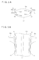
- FIG. 5A is a plan view showing the state in which a folding-in member is pressed against a tubular film.
- FIG. 5B is a front view showing the state in which the folding-in member is pressed against a tubular film.
- FIG. 6 is a schematic view showing the thermocompression bonding and cutting operations of the transverse sealing mechanism.
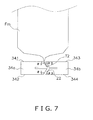
- FIG. 7 is an enlarged view showing the pair of sealing jaws of the transverse sealing mechanism.
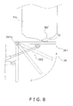
- FIG. 8 is a view showing the operation of a seal orientation correcting mechanism for correcting the orientation of a bottom transverse seal area.
- FIG. 9 is a view showing the state in which a forward/backward-moving cylinder moved contact members toward a tubular bag.
- FIG. 10 is a view showing the state in which an upward/downward-moving cylinder moved the contact members downward.
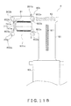
- FIG. 11A is a view showing a delivery mechanism, as well as the bag receiving part and the contact member as components of the bottom-forming mechanism.
- FIG. 11B is a view showing the state in which a tubular bag was dropped in FIG. 11A .
- FIG. 11C is a view showing the state in which the contact members were moved by the forward/backward-moving cylinder following FIG. 11B .
- FIG. 11D is a view showing the state in which the contact members were moved by the upward/downward-moving cylinder following FIG. 11C .
- FIG. 11E is a view showing the state in which the gusset bag was delivered to a intermediate path.
- FIG. 11F is a view showing the state in which the gusset bag has been pushed downstream by a discharge pusher.
- FIG. 11G is a view showing the state in which a new tubular bag was dropped to the bag receiving part following FIG. 11F .
- FIG. 11H is a view showing the state in which a plurality of gusset bags was delivered to the intermediate path.
- FIG. 12A is a front view of a horizontal plane according to a modified example (B).
- FIG. 12B is a view showing a bag receiving part and a vacuum according to a modified example (B).
- FIG. 13 is a view showing a seal orientation correcting mechanism for correcting the orientation of a bottom transverse seal area according to a modified example (C).
- FIG. 10 An embodiment of a bag-making packaging machine 10 according to the present invention is described below while referring to the drawings.
- the terms “left” and “right” of the bag-making packaging machine 10 refer to the case when the bag-making packaging machine 10 is viewed from the front.
- the terms “upstream” and “downstream” of the bag-making packaging machine 10 indicate upstream and downstream in the direction of transport of a film F.
- FIG. 1B is a perspective view of the gusset bag B2.
- the gusset bag B2 has four side parts F1 through F4 and one bottom part BB.
- the gusset bag B2 is a free-standing bag having the bottom part BB as a support plane.
- the gusset bag B2 is formed having folded-in parts (gussets) G, G; four hem parts H1 through H4; a longitudinal seal area L1; a top transverse seal area T1; and a bottom transverse seal area T2.
- the gusset bag B2 is formed so that a front and a back are made wider than two sides.
- the front of the gusset bag B2 is the side part F1 on which the longitudinal seal area L1 is formed among the four side parts F1 through F4.
- the bag-making packaging machine 10 is a machine for packing a product such as a snack food into a bag.
- the bag-making packaging machine 10 primarily includes a bag-making packaging unit 6 for packing a product into a bag, and a film-feeding unit 5 for feeding a sheet-form film F to be made into a gusset bag B2 to the bag-making packaging unit 6.
- Operational switches 18 are disposed facing the front on the right side of the bag-making packaging unit 6.
- a liquid crystal display 19 for showing the operational state is disposed in a position that is visible to a user who operates the operational switches 18.
- the configuration of each part of the bag-making packaging machine 10 is described below.
- the film-feeding unit 5 is a unit for feeding a sheet-form film F to the bag-making packaging unit 6 to be described later.
- the film-feeding unit 5 feeds the sheet-form film F so as to be synchronous with operation of a pull-down belt mechanism 32 to be described later.
- the bag-making packaging unit 6 loads a confectionery or other article being packaged, which was weighed by a combination weighing device 2 shown in FIG. 1A , while forming the sheet-form film F delivered from the film-feeding unit 5 into a polygonal tubular form, and forms a gusset bag B2.
- the sheet-form film F is deformed by each mechanism shown in FIGS. 2A and 2B into a polygonal tubular film Fm, a tubular bag B1, and finally a gusset bag B2.
- the bag-making packaging unit 6 primarily includes a hem-forming mechanism 61, a molding mechanism 31, a pull-down belt mechanism 32, a longitudinal sealing mechanism 33, a gusset-forming mechanism 35, a transverse sealing mechanism 34, a seal orientation correcting mechanism 36 for correcting the orientation of a bottom transverse seal area, a bottom-forming mechanism 7, and a delivery mechanism 8.
- FIG. 3 is a schematic cross-sectional view of the hem-forming mechanism 61.
- the hem-forming mechanism 61 is configured to form hem parts H1 through H4 in the sheet-form film F.
- the hem-forming mechanism 61 is disposed between the film-feeding unit 6 and the molding mechanism 31 to be described later. Specifically, the hem-forming mechanism 61 is disposed in the region indicated by the double-dotted broken line R1 in FIG. 2B .
- the hem-forming mechanism 61 primarily includes a transport plane 610, insertion members 611, heater blocks 612, and a plurality of pairs of rollers (not shown).
- the insertion members 611 are members that are inserted from above into the slots formed on the above transport plane 610. Four insertion members 611 are disposed in the width direction of the film F. The film F passing in the vicinity of the slots on the transport plane 610 comes into contact with the insertion members 611 and is inserted into the slots. Parts H1' through H4' corresponding to hem parts are thereby formed on prescribed parts of the film F.
- the heater blocks 612 are disposed on both sides in the length direction of the slots formed on the transport plane 610.
- the heater blocks 612 apply heat from both sides to the parts H1' through H4' corresponding to hem parts that are inserted into the slots of the transport plane 610 by the above insertion members 611.
- Pairs of rollers (not shown) are disposed on the downstream side of the transport plane 610.
- the pairs of rollers sandwich from both sides the parts H1' through H4' corresponding to hem parts that are formed on the upstream side of the transport plane 610, and bond the opposite sides of the film F. Hem parts H1 through H4 are thereby formed on the sheet-form film F.
- the tube 31a is a polygonal tubular member and is open on the top and bottom ends.
- An article C to be packaged, which was weighed by the combination weighing device 2 is introduced into the opening on the top end of the tube 31a.
- Guides 312, 312, ... are provided at the opening on the bottom end of the tube 31a.
- the guides 312, 312, ... are members in the form of thin plates that extend in the downstream direction from four corners of the opening on the bottom end.
- the film F is transported in the downstream direction along the surface of the tube 31a.
- the pull-down belt mechanism 32 is described next with reference to FIGS. 2A and 2B .
- the pull-down belt mechanism 32 continuously transports a film F that has been made into tubular form (hereinafter, "polygonal tubular film Fm").
- the pull-down belt mechanism 32 is a mechanism for attaching and continuously transporting downward the polygonal tubular film Fm wrapped on the tube 31a.
- Belts 32a are provided on both the left and right sides of the tube 31a, holding the tube in between.
- the belts 32a hold the polygonal tubular film Fm in contact with the belts.
- the longitudinal sealing mechanism 33 is described next with reference to FIG. 2A .
- the gusset-forming mechanism 35 is described next with reference to FIGS. 2A , 2B , 4 , 5A, and 5B .
- the transverse sealing mechanism 34 is described next with reference to FIGS. 2A , 2B , 6 , and 7 .
- the transverse sealing mechanism 34 preferably constitutes a bag-producing part of the present embodiment.
- the transverse sealing mechanism 34 transversely seals the polygonal tubular film Fm to close the top and the bottom ends of the bag B. As shown in FIGS. 2A and 2B , the transverse sealing mechanism 34 is disposed below the gusset-forming mechanism 35.
- One of the sealing jaws 34a has an internal cutter (not shown), and the center of the heat-sealed area is cut transversely by the cutter in a single cutting operation.
- the tubular bag B1 is thereby cut off from the longitudinally extending polygonal tubular film Fm.
- a gap 22 that is V-shaped in cross section is formed between the opposite faces of the sealing jaws 34a, 34b by interlocking of the projected opposite face of the forward sealing jaw 34a and the recessed opposite face of the rear sealing jaw 34b.
- the transverse seal areas T1, T2 sandwiched in the gap 22 between the forward sealing jaw 34a and the rear sealing jaw 34b is therefore inclined in one direction.
- FIG. 8 is a right side view of the seal orientation correcting mechanism 36.
- One end in the short direction of the member 361 for pushing up a bottom transverse seal area is fixed to a support shaft 361a.
- the support shaft 361a is attached to an internal frame (not shown) of the bag-making packaging unit 6 on the front side of the tubular bag B1.
- the member 361 for pushing up a bottom transverse seal area is configured to be movable up and down about the support shaft 361a.
- the other end in the short direction of the member 361 for pushing up a bottom transverse seal area is movable about the support shaft 361a. That is, the member 361 for pushing up a bottom transverse seal area is moved up and down by the driving of the support member 362 to be described later, and comes into contact with the bottom transverse seal area T2 in the up position.
- the support member 362 is a member that supports the member 361 for pushing up a bottom transverse seal area from below.
- One end of the support member 362 also is attached to the internal frame (not shown) of the bag-making packaging unit 6.
- the other end of the support member 362 is attached to the bottom face of the member 361 for pushing up a bottom transverse seal area, that is, to the face on the side opposite the face that comes into contact with the bottom transverse seal area T2.
- the support member 362 has an extendable mechanism.
- the support member 362 extends and retracts at a prescribed timing by a motor (not shown).
- the "prescribed timing" is after the bottom transverse seal area T2 is formed and before the tubular bag B1 is cut off from the polygonal tubular film Fm.
- the support member 362 thereby causes the member 361 for pushing up a bottom transverse seal area to move up and down.
- FIGS. 9 and 10 are right side views of the bottom-forming mechanism 7.
- FIG. 11A is a view showing the bag receiving part 71 of the bottom-forming mechanism 7, and a delivery mechanism 8 to be described later.
- the bottom-forming mechanism 7 is disposed downstream of the above transverse sealing mechanism 34 and adjusts the form of the tubular bag B1. Specifically, the bottom-forming mechanism 7 forms the following parts into a flat bottom part BB: the bottom transverse seal area T2 provided to the tubular bag B1, the part BB' corresponding to a bottom part of the tubular bag B1, and the main body disposed in the vicinity of the part BB' corresponding to a bottom part; and forms a gusset bag B2 having an appropriate rectangular bottom shape.
- the horizontal plane 710 is a plate formed by a plate member that is made of material having high thermal conductivity.
- An example of a material having high thermal conductivity is aluminum.
- the horizontal plane 710 has a rectangular shape.
- the length in the long direction of the horizontal plane 710 is about equal to the width of the front surface and back surface of the tubular bag B1.
- the length in the short direction of the horizontal plane 710 is about equal to the width of the right side and left side of the tubular bag B1.
- the bottom transverse seal area T2, and a part (part BB' corresponding to a bottom part) of the main body of the tubular bag B1 come into contact with the horizontal plane 710.
- a heater 710b that extends in the long direction of the horizontal plane 710 is provided in the center of the horizontal plane 710.
- a plurality of holes 710a, 710a,... is formed on the horizontal plane 710. Specifically, as shown in FIG. 11A , the plurality of holes 710a, 710a, ... is formed in two rows in the long direction. More specifically, the two rows of holes 710a, 710a, ... arranged in the long direction are disposed one row each substantially horizontally on both sides of the above-described heater 710b.
- the vertical planes 711a, 711 b include a front-side vertical plane 711a, that faces the front surface of the tubular bag B1, and a back-side vertical plane 71 1b, that faces the back surface of the tubular bag B1.
- the vertical planes 711a, 711b rise perpendicularly from the horizontal plane 710. That is, the front-side vertical plane 711a rises perpendicularly from the front side of the horizontal plane 710, and the back-side vertical plane 711 b rises perpendicularly from the back side of the horizontal plane 710.
- the vacuum devices 73, 73 suction the part BB' corresponding to a bottom part, and also draw the main body in the vicinity of the part BB' corresponding to a bottom part via the plurality of holes 710a, 710a, ... provided on the above horizontal plane 710 by suction.
- the vacuum devices 73, 73 are provided in accordance with the number of rows of the plurality of holes 710a, 710a. That is, as shown in FIGS. 9 and 10 , one vacuum device 73 is connected to the row of the plurality of holes 710a, 710a, ... disposed on the front side of the tubular bag B1, and one vacuum device 73 is connected also to the row of the plurality of holes 710a, 710a, ... disposed on the back side of the tubular bag B1. Since the part BB' of the bag B1 is drawn toward the horizontal plane 710 via the plurality of ho les 710a, 710a, ..., the bag B1 can be drawn in a wide range.
- the contact members 741a, 741b are rectangular flat plate members having a width about equal to the width of the front surface and back surface of the tubular bag B1.
- the contact members 741a, 741b include a front-side contact member 741a capable of coming into contact with the front of the tubular bag B1, and a back-side contact member 741b capable of coming into contact with the back of the tubular bag B1.
- the front-side contact member 741a and the back-side contact member 741b are each inclined at a prescribed angle ⁇ 3 with respect to the tubular bag B1.
- the moving units 742a, 742b, 743a, 743b move the contact members 741a, 741b, bring the contact members 741a, 741b into contact with the top of the main body of the tubular bag B1 to apply force, and move the contact members 741a, 741b away from the bag.
- the moving units 742a, 742b, 743a, 743b include forward/backward-moving cylinders 742a, 742b for moving the contact members 741a, 741b forward and backward with respect to the tubular bag B1, and upward/downward-moving cylinders 743a, 743b for moving the contact members 741a, 741b upward and downward with respect to the tubular bag B1.
- the forward/backward-moving cylinders 742a, 742b include a front-side forward/backward-moving cylinder 742a disposed on the front side of the tubular bag B1, and a back-side forward/backward-moving cylinder 742b disposed on the back side of the tubular bag B1.
- the upward/downward-moving cylinders 743a, 743b include a front-side upward/downward-moving cylinder 743a disposed on the front side of the tubular bag B1, and a back-side upward/downward-moving cylinder 743b disposed on the back side of the tubular bag B1.
- the forward/backward-moving cylinders 742a, 742b are fixed via connection members 76, 76 to the upward/downward-moving cylinders 743a, 743b to be described later.
- the front-side forward/backward-moving cylinder 742a is fixed via a connection member 76 to the front-side upward/downward-moving cylinder 743a
- the back-side forward/backward-moving cylinder 742b is fixed via a connection member 76 to the back-side upward/downward-moving cylinder 743b.
- the forward/backward-moving cylinders 742a, 742b extend in the directions indicated by arrows A1, A1 in FIG. 9 , and retract in the directions opposite the directions indicated by arrows A1, A1.
- the forward/backward-moving cylinders 742a, 742b thereby cause the contact members 741a, 741b to come into contact with and withdraw from the top of the main body of the tubular bag B1 via the upward/downward-moving cylinders 743a, 743b.
- the upward/downward-moving cylinders 743a, 743b are fixed to the contact members 741a, 741b via support members 75, 75 for supporting the above contact members 741a, 741b.
- the front-side upward/downward-moving cylinder 743a is fixed to the front-side contact member 741a via a support member 75.
- the back-side upward/downward-moving cylinder 743b is fixed to the back-side contact member 741b via a support member 75.
- the upward/downward-moving cylinders 743a, 743b extend in the directions indicated by arrows A2, A2 in FIG. 10 , and retract in the directions opposite the directions indicated by arrows A2, A2.
- the upward/downward-moving cylinders 743a, 743b thereby move the contact members 741a, 741b upward and downward. More specifically, the upward/downward-moving cylinders 743a, 743b move the bottom ends of the contact members 741a, 741b from the upward position P1 shown in FIGS. 9 and 10 to the downward position P2 shown in FIG. 10 .
- the distance d between the upward position P1 and the downward position P2 is about 1 cm.
- the bottom transverse seal area T2 the part BB' corresponding to a bottom part, and the main body in the vicinity of the part BB' corresponding to a bottom part of the tubular bag B1 are deformed by the upward/downward-moving cylinders 743a, 743b so as to adhere closely to the horizontal plane 710, the front-side vertical plane 711a, and the back-side vertical plane 711 b.
- a bottom part BB is thereby formed on the tubular bag B1, and a gusset bag B2 having a desired rectangular bottom shape is formed.
- FIGS. 11A through 11H are plan views showing the horizontal plane 710 and the contact members 741a, 741b of the bottom-forming mechanism 7, and the delivery mechanism 8.
- the delivery mechanism 8 is a mechanism for delivering a gusset bag B2, which is a tubular bag B1 on which a bottom part BB was formed by the bottom-forming mechanism 7, to a packing stage. As shown in FIGS. 11A through 11H , the gusset bag B2 is transported on a roughly L-shaped course.
- the delivery mechanism 8 primarily includes delivery parts 80a, 80b, a intermediate path 81, a discharge pusher 82, and a belt conveyer 83.
- the delivery parts 80a, 80b deliver the gusset bag B2 from the bag receiving part 71 to the intermediate path 81 to be described later.
- the delivery parts 80a, 80b include a front-side delivery part 80a positioned on the front side of the gusset bag B2, and a bag-side delivery part 80b positioned on the back side of the gusset bag B2.
- the delivery parts 80a, 80b deliver the gusset bag from the bag receiving part 71 to the intermediate path 81 using both the front-side delivery part 80a and the back-side delivery part 80b.
- the delivery parts 80a, 80b primarily comprise pairs of belts 801a, 801b; rollers 802a, 802a, 802b, 802b for driving each belt 801a, 801b; and fins 803a, 803a, 803b, 803b attached to the surface of each belt 801a, 801b, that is, to the contact face contacted by the gusset bag B2.
- the delivery part 80a positioned on the front side of the gusset bag B2 includes the belt 801a, the rollers 802a, 802a for driving the belt 801a, and the fins 803a, 803a attached to the contact face of the belt 801a.
- the delivery part 80b positioned on the back side of the gusset bag B2 includes the belt 801b, the rollers 802b, 802b for driving the belt 801b, and the fins 803b, 803b attached to the contact face of the belt 801b.
- the rollers 802a, 802a, 802b, 802b are disposed on the insides of the aforementioned belts 801a, 801b.
- the rollers 802a, 802a are provided on the inside of the belt 801a disposed on the front side of the gusset bag B2.
- the rollers 802b, 802b are provided on the inside of the belt 801b disposed on the back side of the gusset bag B2.
- Either roller 802a of the two rollers 802a, 802a disposed on the inside of one belt 801a is driven by a roller drive motor (not shown).
- the other roller 802a rotates together with the rotation of the one roller 802a.
- the two fins 803a, 803a, 803b, 803b attached to each of the belts 801a, 801b are disposed on the contact faces of the belts 801a, 801b so as to be in mutually point-symmetric positions.
- the fins 803b, 803b are disposed in positions that are symmetric with respect to the center point O of the delivery part 80b. Therefore in the case when one fin 803a, 803b of the two fins 803a, 803a, 803b, 803b is in contact with the gusset bag B2, the other fin 803a, 803b does not contact the gusset bag B2.
- the belts 801a, 801b move in synchronization.
- One fin 803a, 803b of each of the belts 801a, 801b (hereinafter, "pair of fins 803a, 803b") thus comes into contact with the gusset bag B2, and the pair of fins 803a, 803b begins to push the gusset bag B2.
- the gusset bag B2 is thereby delivered to the upstream side of the adjacent intermediate path 81.
- the gusset bag B2 is delivered from the horizontal plane 710 to the intermediate path 81 in a state in which the front is oriented toward the belt conveyer 83 to be described later, and stands upright on one end of the upstream side of the intermediate path 81.
- the intermediate path 81 is a course or path for connecting the bottom-forming mechanism 7 and the belt conveyer 83. Specifically, the intermediate path 81 is used for conveying the gusset bag B2 delivered from the bottom-forming mechanism 7 by the delivery parts 80a, 80b to the belt conveyer 83 to be described later.
- the height of the end of the transport plane on the upstream side of the intermediate path 81 is about equal to the horizontal plane 710 of the bottom-forming mechanism 7.
- the height of the end on the downstream side of the intermediate path 81 is about equal to the height of the end on the upstream side of the belt conveyer 83.
- the discharge pusher 82 is provided at one end on the upstream side of the intermediate path 81.
- the discharge pusher 82 has a contact face that is brought into contact with the back of the gusset bag B2.
- the contact face of the discharge pusher 82 can be moved forward and backward.
- the discharge pusher 82 comes into contact with the back of the gusset bag B2 delivered to the end on the upstream side of the intermediate path 81.
- the discharge pusher 82 moves the contact face forward (downstream) at a prescribed time interval (refer to FIG. 11F ).
- the gusset bag B2 is thereby moved from the upstream side to the downstream side of the intermediate path 81. More specifically, the gusset bag B2 is pushed from the most upstream region of the intermediate path 81, that is, from the position on a straight line from the horizontal plane 710 of the bottom-forming mechanism 7.
- the film-feeding unit 5 feeds a sheet-form film F to the bag-making packaging unit 6.
- the sheet-form film F fed by the film-feeding unit 5 first passes through the hem-forming mechanism 61 (refer to FIG. 3 ). Hem parts H1 through H4 are formed on the sheet-form film F.
- the sheet-form film F then passes through the molding mechanism 31 (refer to FIGS. 2A and 2B ).
- the sheet-form film F by passing through the molding mechanism 31 is molded into a polygonal tubular film Fm having hem parts H1 through H4.
- the polygonal tubular film Fm is transported downstream by the pull-down belt mechanism 32.
- the overlapping parts of the polygonal tubular film Fm transported downstream are heated and bonded by the longitudinal sealing mechanism 33.
- a longitudinal seal area L 1 is thereby formed on the polygonal tubular film Fm.
- the polygonal tubular film Fm next is sent to the gusset-forming mechanism 35 (refer to FIG. 4 ).
- the polygonal tubular film Fm is held between the folding-in members 35a, 35b and the guides 312, 312,... and is folded (refer to FIG. 5A ). Gussets G, G are thereby formed on the polygonal tubular film Fm.
- the polygonal tubular film Fm is transported further downstream and is transversely sealed by the transverse sealing mechanism 34 (refer to FIG. 6 ). Specifically, the transverse sealing mechanism 34 first forms a bottom transverse seal area T2 on the polygonal tubular film Fm.
- the article C to be packaged which was weighed by the combination weighing device 2, is introduced from the tube 31a into the polygonal tubular film Fm at the timing in which the transverse sealing mechanism 34 forms or formed the bottom transverse seal area T2.
- the bottom transverse seal area T2 is inclined at a prescribed angle by the gap 22 formed between the pair of sealing jaws 34a, 34b (refer to FIG. 7 ).
- the bottom transverse seal area T2 inclined at a prescribed angle is further inclined by the seal orientation correcting mechanism 36, and is brought into contact with the part BB' corresponding to a bottom part of the tubular bag B1 (refer to FIG. 8 ).
- the transverse sealing mechanism 34 further forms a top transverse seal area T1 on the polygonal tubular film Fm.
- the transverse sealing mechanism 34 cuts the center of the top transverse seal area T1 by a cutter (not shown).
- the tubular bag B1 is thereby cut off from the polygonal tubular film Fm.
- the dropped tubular bag B1 is first received and held by the bag receiving part 71 (refer to FIG. 11B ).
- the pressing mechanism 74 comes into contact with the top of the tubular bag B1, and presses the tubular bag B1 against the bag receiving part 71 (refer to FIGS. 9 and 11C , and FIGS. 10 and 11D ).
- the front-side contact member 741a disposed on the front side of the tubular bag B1, and the back-side contact member 741b disposed on the back side of the tubular bag B1 are moved toward the tubular bag B1 by the forward/backward-moving cylinders 742a, 742b, respectively, to correct the orientation of the tubular bag B1 (refer to FIGS. 9 and 11C ).
- the front-side contact member 741a and the back-side contact member 741b are pushed downward by the upward/downward-moving cylinders 743a, 743b, and a downward force is applied to the tubular bag B1 (refer to FIGS. 10 and 11D ).
- the heater 710b (heating unit) installed in the horizontal plane 710 is in the ON state. Heat is therefore applied by the heater 710b to the overlapping portion of the bottom transverse seal area T2 and the part BB' corresponding to a bottom part, which is a portion in contact with the heater 710b.
- the bottom transverse seal area T2 and the part BB' of the main body can thereby be made to adhere firmly.
- the vacuum devices 73, 73 also are in the ON state.
- the vacuum devices 73, 73 therefore suction the part BB' corresponding to a bottom part, and the main body in the vicinity of the part BB' corresponding to a bottom part of the tubular bag B1, which are pressed against the horizontal plane, via the plurality of holes 710a, 710a, ... formed in the horizontal plane 710.
- the gusset bag B2 is delivered from the bottom-forming mechanism 7 to the intermediate path 81 by the delivery parts 80a, 80b (refer to FIG. 11E ).
- the back of the gusset bag B2 delivered to the intermediate path 81 is pushed by the discharge pusher 82 at a prescribed time interval, and the gusset bag B2 moves downstream (refer to FIG. 11F ).
- a new tubular bag B1 drops onto the bag receiving part 71 (refer to FIG. 11G ).
- a plurality of gusset bags B2, B2, B2 continues in a line on the intermediate path 81 (refer to FIG. 11H ).
- the leading gusset bag B2 of the plurality of gusset bags B2, B2, B2 lined up on the intermediate path 81 is delivered to the belt conveyer 83 so as to be pushed by the subsequent gusset bags B2, B2, B2.
- the bottom-forming mechanism 7 is provided below the transverse sealing mechanism 34.
- the bottom-forming mechanism 7 receives and holds the dropped tubular bag B1 at the bag receiving part 71, and forms the bottom part BB on the gusset bag B2.
- the bottom part BB can be formed stably by utilizing the weight of the article being packaged. That is, the overlapping portion of the bottom transverse seal area T2 and the part BB' corresponding to a bottom part can be adequately thermocompression bonded by the weight of the article being packaged, and a bottom part BB having sufficient surface area can be formed.
- the operating speed of the bag-making packaging machine 10 can be maintained, and gusset-type bags can be formed quickly.
- the bag-making packaging machine 10 has a pressing mechanism 74.
- the forward/backward-moving cylinders 742a, 742b operate when a tubular bag B1 drops onto the bag receiving part 71, and the front-side contact member 741a and the back-side contact member 741b come into contact with the tubular bag B1 from the front side and back side of the tubular bag B1.
- the tubular bag B1 can thereby be brought to a proper angle even in the case, for example, when the tubular bag B1 is inclined when dropped onto the bag receiving part 71.
- the front-side contact member 741a and the back-side contact member 741b are inclined at a prescribed angle with respect to the tubular bag B1.
- a downward force is therefore applied to the tubular bag B1 even in the case when the front-side contact member 741a and the back-side contact member 741b are moved and brought into contact with the tubular bag B1 by the forward/backward-moving cylinders 742a, 742b.
- the gusset bag B2 can thereby be formed while the tubular bag B1 is stabilized.
- a heater 710b is installed in the horizontal plane 710 of the bag receiving part 71.
- the bottom transverse seal area T2 can therefore be made to adhere closely to the part BB' corresponding to a bottom area.
- the gap 22 formed between the opposite faces of the pair of sealing jaws 34a, 34b is roughly V-shaped.
- a bottom transverse seal area T2 inclined in a fixed direction is thereby formed.
- the bottom transverse seal area T2 is inclined further by the seal orientation correcting mechanism 36 for correcting the orientation of a bottom transverse seal area before the tubular bag B1 is cut off from the polygonal tubular film Fm.
- the bottom transverse seal area T2 can thereby be brought into contact with the part BB' corresponding to a bottom part when the tubular bag B1 drops onto the bag receiving part 71.
- the number of vacuum devices 73 may be provided in a plurality corresponding to the number of rows of holes of holes 710a, 710a, ... as shown in FIG. 12B .
- the main body of the tubular bag B1 may be drawn or sucked first by the vacuums in the vicinity of the center. That is, the vacuum devices 73a, 73a first suction the main body of the tubular bag B1 via the holes in the vicinity of the heater 710b, and the main body of the tubular bag B1 is then drawn with the vacuum devices 73b, 73b.
- the surface area of the main body of the tubular bag B1 made to adhere closely to the horizontal plane 710 can thereby be widened gradually. That is, the shape of the bottom part BB of the gusset bag B2 can be securely brought close to the desired shape.
- the width of the member 361 for pushing up a bottom transverse seal area is about equal to the width of the front and back of the tubular bag B1, but the width of the member 361 for pushing up a bottom transverse seal area may be a width that ensures partial contact with the bottom transverse seal area.
- the length of the member 361 for pushing up a bottom transverse seal area is about equal to the width of the right side and left side of the tubular bag B1, but the member may have a length sufficient to provide contact with the bottom transverse seal area T2.
- a heater 361b may be installed in the member 361 for pushing up a bottom transverse seal area.
- the bottom transverse seal area T2 and the main body can thereby adhere more firmly.
- the contact members 741a, 741b are moved using the forward/backward-moving cylinders 742a, 742b and the upward/downward-moving cylinders 743 a, 743b when the tubular bag B1 is pressed with the pressing mechanism 74, but the tubular bag B1 may be pressed to the bag receiving part 71 using cylinders that move the contact members 741a, 741b diagonally instead of the forward/backward-moving cylinders 742a, 742b and the upward/downward-moving cylinders 743a, 743b.
- the bag-making packaging machine of the present invention can be used widely as a bag-making packaging machine capable of forming a gusset-type bag without a marked reduction of manufacturing speed.
- the term “comprising” and its derivatives, as used herein, are intended to be open ended terms that specify the presence of the stated features, elements, components, groups, integers, and/or steps, but do not exclude the presence of other unstated features, elements, components, groups, integers and/or steps.
- the foregoing also applies to words having similar meanings such as the terms, “including”, “having” and their derivatives.
- the terms “part,” “section,” “portion,” “member” or “element” when used in the singular can have the dual meaning of a single part or a plurality of parts.
- the terms of degree such as “substantially”, “about” and “approximately” as used herein mean a reasonable amount of deviation of the modified term such that the end result is not significantly changed.
Landscapes
- Engineering & Computer Science (AREA)
- Mechanical Engineering (AREA)
- Containers And Plastic Fillers For Packaging (AREA)
- Auxiliary Devices For And Details Of Packaging Control (AREA)
Applications Claiming Priority (1)
| Application Number | Priority Date | Filing Date | Title |
|---|---|---|---|
| JP2009030684A JP2010184732A (ja) | 2009-02-13 | 2009-02-13 | 製袋包装機 |
Publications (2)
| Publication Number | Publication Date |
|---|---|
| EP2218647A1 true EP2218647A1 (fr) | 2010-08-18 |
| EP2218647B1 EP2218647B1 (fr) | 2011-07-13 |
Family
ID=42174143
Family Applications (1)
| Application Number | Title | Priority Date | Filing Date |
|---|---|---|---|
| EP10153541A Not-in-force EP2218647B1 (fr) | 2009-02-13 | 2010-02-12 | Machine d'emballage pour fabrication de sacs |
Country Status (6)
| Country | Link |
|---|---|
| US (2) | US8376923B2 (fr) |
| EP (1) | EP2218647B1 (fr) |
| JP (1) | JP2010184732A (fr) |
| CN (1) | CN101804871B (fr) |
| AT (1) | ATE516212T1 (fr) |
| AU (1) | AU2010200532B2 (fr) |
Cited By (1)
| Publication number | Priority date | Publication date | Assignee | Title |
|---|---|---|---|---|
| US11667415B2 (en) | 2015-03-18 | 2023-06-06 | Kellogg Company | Flat-bottom stand-up bag, vertical form, fill, and seal system and methodology for utilizing the same |
Families Citing this family (18)
| Publication number | Priority date | Publication date | Assignee | Title |
|---|---|---|---|---|
| US9296171B2 (en) * | 2008-03-11 | 2016-03-29 | Frito-Lay North America, Inc. | Method for making a flat bottom pillow pouch |
| JP2012136271A (ja) * | 2010-12-27 | 2012-07-19 | Ishida Co Ltd | 製袋包装機 |
| US20130330027A1 (en) * | 2011-02-24 | 2013-12-12 | Suzanne Emma Axe | Infusion packet and its manufacture |
| JP5749939B2 (ja) * | 2011-03-02 | 2015-07-15 | 株式会社イシダ | 製袋包装機 |
| CN103204265A (zh) * | 2012-09-20 | 2013-07-17 | 佛山市德亦宝机械制造有限公司 | 一种快速包装机及包装工艺 |
| WO2014096270A1 (fr) | 2012-12-20 | 2014-06-26 | Nestec S.A. | Sachet souple ayant une ouverture plus grande |
| JP2013100141A (ja) * | 2013-03-06 | 2013-05-23 | Ishida Co Ltd | 製袋包装機 |
| US9902517B2 (en) * | 2013-11-01 | 2018-02-27 | Frito-Lay North America, Inc. | Apparatus and method for a structurally resilient package |
| US9840346B2 (en) * | 2013-11-01 | 2017-12-12 | Frito-Lay North America, Inc. | Method and apparatus for making a structurally resilient package |
| CZ2014199A3 (cs) * | 2014-03-27 | 2015-06-03 | Velteko S.R.O. | Způsob výroby foliového hadicového sáčku a vertikální hadicový balicí stroj k provádění tohoto způsobu |
| JP5688867B1 (ja) * | 2014-06-11 | 2015-03-25 | トタニ技研工業株式会社 | 製袋機 |
| US9510713B2 (en) * | 2014-08-25 | 2016-12-06 | II Joe Thomas Farris | Methods for sewing T-pocket towels |
| CN104743174B (zh) * | 2015-03-05 | 2017-01-04 | 广西力源宝科技有限公司 | 一种自动包装袋口整形机 |
| CN106364704A (zh) * | 2016-11-19 | 2017-02-01 | 无锡当升智能装备科技有限公司 | 包装件压实机构 |
| CN106428666A (zh) * | 2016-11-19 | 2017-02-22 | 无锡当升智能装备科技有限公司 | 包装袋的挤压压实机构 |
| CN106882434A (zh) * | 2017-04-26 | 2017-06-23 | 福建省安溪县兴安金属有限公司 | 一种用于纯电动整形包装机中的袋体整形装置及整形方法 |
| DE102018117871A1 (de) * | 2018-07-24 | 2020-01-30 | Haver & Boecker Ohg | Vorrichtung und Verfahren zur Herstellung wenigstens eines leeren offenen Sackes |
| CN109109385A (zh) * | 2018-09-27 | 2019-01-01 | 常州市劲普自动化设备有限公司 | 一种编织袋袋口折叠机构 |
Citations (4)
| Publication number | Priority date | Publication date | Assignee | Title |
|---|---|---|---|---|
| US3332198A (en) * | 1964-04-21 | 1967-07-25 | Holstein & Kappert Maschf | Process for the production and filling of bags or the like |
| US3857223A (en) | 1973-02-13 | 1974-12-31 | A Dominici | Package forming device |
| JP2000335511A (ja) | 1999-05-27 | 2000-12-05 | Tokyo Autom Mach Works Ltd | 縦型製袋充填包装機の平底形成装置 |
| US20010029721A1 (en) * | 2000-04-14 | 2001-10-18 | Shikoku Kakoki Co., Ltd. | Container forming device |
Family Cites Families (26)
| Publication number | Priority date | Publication date | Assignee | Title |
|---|---|---|---|---|
| US2481611A (en) * | 1941-01-23 | 1949-09-13 | Shellmar Products Corp | Apparatus for packing coffee |
| US3050916A (en) * | 1961-04-24 | 1962-08-28 | Hayssen Mfg Company | Packaging machine film sealing mechanism |
| US3543477A (en) * | 1967-12-19 | 1970-12-01 | Mira Pak Inc | Apparatus for packaging with hinged plate for forming flat bottom package |
| US3603217A (en) * | 1969-01-16 | 1971-09-07 | Robinson E S & A Canada | Method of forming a bag |
| US3924521A (en) * | 1974-05-22 | 1975-12-09 | Violet M Hanson | Method for forming flat bottom plastic bags |
| US4079662A (en) * | 1976-11-30 | 1978-03-21 | Triangle Package Machinery Company | Bag making machine |
| JPS6013882B2 (ja) * | 1977-02-10 | 1985-04-10 | 武田薬品工業株式会社 | 整袋装置 |
| CA1126150A (fr) * | 1978-09-12 | 1982-06-22 | Frederick W. Beer | Contenants, et methode de faconnage automatique connexe |
| JPH0714723B2 (ja) * | 1986-09-04 | 1995-02-22 | 雪印乳業株式会社 | 粉体包装工程における袋の荷姿修正装置 |
| US5195829A (en) * | 1990-10-26 | 1993-03-23 | Golden Valley Microwave Foods Inc. | Flat bottomed stand-up microwave corn popping bag |
| DE4218810C2 (de) * | 1992-06-06 | 1996-02-15 | Rovema Gmbh | Schlauchbeutelmaschine zum kontinuierlichen Herstellung von mit Seitenfalten vesehenen Packungen |
| JPH06336229A (ja) * | 1993-05-25 | 1994-12-06 | Asahi Kinzoku:Kk | 小袋送り装置 |
| JPH0885505A (ja) * | 1994-09-20 | 1996-04-02 | Tokyo Autom Mach Works Ltd | 製袋充填包装装置及び包装袋 |
| JP3413539B2 (ja) * | 1995-03-08 | 2003-06-03 | 四国化工機株式会社 | 液体充填チューブのヒートシール装置 |
| JPH10218119A (ja) * | 1997-02-10 | 1998-08-18 | Fujikura Kousou Kk | 繊維製品の収納装置およびその収納方法 |
| IT1305240B1 (it) * | 1998-06-04 | 2001-04-19 | Burgopack Stampa Trasformazione Imballaggi Spa | Un procedimento per realizzare confezioni a tubo in materialeflessibile, una apparecchiatura per effettuare il procedimento ed una |
| FR2781718B1 (fr) * | 1998-07-28 | 2000-10-13 | Flexico France Sarl | Procede de fabrication de sacs a fond plat et machine pour sa mise en oeuvre |
| US6052971A (en) * | 1998-11-09 | 2000-04-25 | Hayssen, Inc. | Offset stripper and stripping method for vertical form, fill and seal machine |
| JP4301481B2 (ja) * | 1999-01-14 | 2009-07-22 | テトラ ラバル ホールデングス アンド ファイナンス エス エイ | 包材のチューブを印刷位置にセットする装置 |
| JP3922928B2 (ja) * | 2002-01-09 | 2007-05-30 | 株式会社東京自働機械製作所 | 縦形製袋充填包装機の角底ガセット袋成形装置 |
| JP2003246308A (ja) * | 2002-02-25 | 2003-09-02 | Nobuyuki Shimomura | 袋整形機 |
| JP4253164B2 (ja) * | 2002-05-17 | 2009-04-08 | 株式会社イシダ | 製袋包装機の横シール機構および製袋包装機 |
| JP4451120B2 (ja) * | 2003-11-26 | 2010-04-14 | 株式会社川島製作所 | 袋包装体成形方法及び装置 |
| CN100575195C (zh) * | 2004-07-05 | 2009-12-30 | 株式会社石田 | 制袋包装系统 |
| JP4857062B2 (ja) * | 2006-09-29 | 2012-01-18 | 株式会社東京自働機械製作所 | 角底袋用縦形製袋充填包装機 |
| CN201010055Y (zh) * | 2007-01-23 | 2008-01-23 | 武汉利德电气有限公司 | 立式包装机 |
-
2009
- 2009-02-13 JP JP2009030684A patent/JP2010184732A/ja active Pending
-
2010
- 2010-02-09 US US12/702,473 patent/US8376923B2/en not_active Expired - Fee Related
- 2010-02-11 CN CN2010101152785A patent/CN101804871B/zh not_active Expired - Fee Related
- 2010-02-12 AU AU2010200532A patent/AU2010200532B2/en not_active Ceased
- 2010-02-12 EP EP10153541A patent/EP2218647B1/fr not_active Not-in-force
- 2010-02-12 AT AT10153541T patent/ATE516212T1/de not_active IP Right Cessation
-
2013
- 2013-01-17 US US13/743,679 patent/US20130130878A1/en not_active Abandoned
Patent Citations (4)
| Publication number | Priority date | Publication date | Assignee | Title |
|---|---|---|---|---|
| US3332198A (en) * | 1964-04-21 | 1967-07-25 | Holstein & Kappert Maschf | Process for the production and filling of bags or the like |
| US3857223A (en) | 1973-02-13 | 1974-12-31 | A Dominici | Package forming device |
| JP2000335511A (ja) | 1999-05-27 | 2000-12-05 | Tokyo Autom Mach Works Ltd | 縦型製袋充填包装機の平底形成装置 |
| US20010029721A1 (en) * | 2000-04-14 | 2001-10-18 | Shikoku Kakoki Co., Ltd. | Container forming device |
Cited By (1)
| Publication number | Priority date | Publication date | Assignee | Title |
|---|---|---|---|---|
| US11667415B2 (en) | 2015-03-18 | 2023-06-06 | Kellogg Company | Flat-bottom stand-up bag, vertical form, fill, and seal system and methodology for utilizing the same |
Also Published As
| Publication number | Publication date |
|---|---|
| AU2010200532A1 (en) | 2010-09-02 |
| CN101804871A (zh) | 2010-08-18 |
| US8376923B2 (en) | 2013-02-19 |
| EP2218647B1 (fr) | 2011-07-13 |
| ATE516212T1 (de) | 2011-07-15 |
| US20100210438A1 (en) | 2010-08-19 |
| CN101804871B (zh) | 2012-04-18 |
| US20130130878A1 (en) | 2013-05-23 |
| AU2010200532B2 (en) | 2014-10-09 |
| JP2010184732A (ja) | 2010-08-26 |
Similar Documents
| Publication | Publication Date | Title |
|---|---|---|
| EP2218647B1 (fr) | Machine d'emballage pour fabrication de sacs | |
| AU2012100233A4 (en) | Bag-making packaging machine | |
| JP4955695B2 (ja) | 縦型充填包装機 | |
| JP2011116436A (ja) | 製袋包装機 | |
| KR101996069B1 (ko) | 에어캡 쇼핑백 제조방법 및 제조장치 | |
| JP4977080B2 (ja) | 横形製袋充填機 | |
| JP2010083563A (ja) | 製袋包装機 | |
| JP5911281B2 (ja) | 開袋装置 | |
| JP2013100141A (ja) | 製袋包装機 | |
| JP5158822B2 (ja) | 袋シール装置 | |
| JP2008168931A (ja) | 製袋包装機の横シール機構 | |
| JP7297357B1 (ja) | 縦型製袋充填包装機、内容物入りフィルム包装袋の製造方法、内容物入りフィルム包装袋 | |
| CN113716082B (zh) | 制袋包装机 | |
| EP1612144A1 (fr) | Procédé et dispositif pour emballer un produit dans des sachets | |
| WO2023085360A1 (fr) | Dispositif de transport, dispositif de fabrication de poche et procédé de fabrication de poche | |
| WO2022014006A1 (fr) | Machine de fabrication et d'emballage de sacs | |
| KR101503862B1 (ko) | 2단 분리형 가로 실링 접합장치를 구비한 액상의 소스류 식품 포장기 | |
| JP4355946B2 (ja) | サンドイッチ包装機の袋口部折り畳み装置 | |
| JP5224339B2 (ja) | 縦形製袋充填包装機 | |
| JP2022135637A (ja) | 縦型充填包装機および被包装物の充填包装方法 | |
| JP3762383B2 (ja) | 充填装置および充填方法 | |
| JP2009161214A (ja) | 袋包装体整形装置 | |
| KR20170021035A (ko) | 제대 충전 포장기 |
Legal Events
| Date | Code | Title | Description |
|---|---|---|---|
| PUAI | Public reference made under article 153(3) epc to a published international application that has entered the european phase |
Free format text: ORIGINAL CODE: 0009012 |
|
| AK | Designated contracting states |
Kind code of ref document: A1 Designated state(s): AT BE BG CH CY CZ DE DK EE ES FI FR GB GR HR HU IE IS IT LI LT LU LV MC MK MT NL NO PL PT RO SE SI SK SM TR |
|
| 17P | Request for examination filed |
Effective date: 20100917 |
|
| GRAP | Despatch of communication of intention to grant a patent |
Free format text: ORIGINAL CODE: EPIDOSNIGR1 |
|
| RIC1 | Information provided on ipc code assigned before grant |
Ipc: B65B 61/24 20060101AFI20110117BHEP |
|
| GRAS | Grant fee paid |
Free format text: ORIGINAL CODE: EPIDOSNIGR3 |
|
| GRAA | (expected) grant |
Free format text: ORIGINAL CODE: 0009210 |
|
| AK | Designated contracting states |
Kind code of ref document: B1 Designated state(s): AT BE BG CH CY CZ DE DK EE ES FI FR GB GR HR HU IE IS IT LI LT LU LV MC MK MT NL NO PL PT RO SE SI SK SM TR |
|
| REG | Reference to a national code |
Ref country code: GB Ref legal event code: FG4D |
|
| REG | Reference to a national code |
Ref country code: CH Ref legal event code: EP |
|
| REG | Reference to a national code |
Ref country code: IE Ref legal event code: FG4D |
|
| REG | Reference to a national code |
Ref country code: DE Ref legal event code: R096 Ref document number: 602010000107 Country of ref document: DE Effective date: 20110901 |
|
| REG | Reference to a national code |
Ref country code: NL Ref legal event code: VDEP Effective date: 20110713 |
|
| REG | Reference to a national code |
Ref country code: AT Ref legal event code: MK05 Ref document number: 516212 Country of ref document: AT Kind code of ref document: T Effective date: 20110713 |
|
| PG25 | Lapsed in a contracting state [announced via postgrant information from national office to epo] |
Ref country code: SE Free format text: LAPSE BECAUSE OF FAILURE TO SUBMIT A TRANSLATION OF THE DESCRIPTION OR TO PAY THE FEE WITHIN THE PRESCRIBED TIME-LIMIT Effective date: 20110713 Ref country code: LT Free format text: LAPSE BECAUSE OF FAILURE TO SUBMIT A TRANSLATION OF THE DESCRIPTION OR TO PAY THE FEE WITHIN THE PRESCRIBED TIME-LIMIT Effective date: 20110713 Ref country code: PT Free format text: LAPSE BECAUSE OF FAILURE TO SUBMIT A TRANSLATION OF THE DESCRIPTION OR TO PAY THE FEE WITHIN THE PRESCRIBED TIME-LIMIT Effective date: 20111114 Ref country code: NO Free format text: LAPSE BECAUSE OF FAILURE TO SUBMIT A TRANSLATION OF THE DESCRIPTION OR TO PAY THE FEE WITHIN THE PRESCRIBED TIME-LIMIT Effective date: 20111013 Ref country code: IS Free format text: LAPSE BECAUSE OF FAILURE TO SUBMIT A TRANSLATION OF THE DESCRIPTION OR TO PAY THE FEE WITHIN THE PRESCRIBED TIME-LIMIT Effective date: 20111113 Ref country code: HR Free format text: LAPSE BECAUSE OF FAILURE TO SUBMIT A TRANSLATION OF THE DESCRIPTION OR TO PAY THE FEE WITHIN THE PRESCRIBED TIME-LIMIT Effective date: 20110713 Ref country code: NL Free format text: LAPSE BECAUSE OF FAILURE TO SUBMIT A TRANSLATION OF THE DESCRIPTION OR TO PAY THE FEE WITHIN THE PRESCRIBED TIME-LIMIT Effective date: 20110713 Ref country code: FI Free format text: LAPSE BECAUSE OF FAILURE TO SUBMIT A TRANSLATION OF THE DESCRIPTION OR TO PAY THE FEE WITHIN THE PRESCRIBED TIME-LIMIT Effective date: 20110713 Ref country code: BE Free format text: LAPSE BECAUSE OF FAILURE TO SUBMIT A TRANSLATION OF THE DESCRIPTION OR TO PAY THE FEE WITHIN THE PRESCRIBED TIME-LIMIT Effective date: 20110713 |
|
| PG25 | Lapsed in a contracting state [announced via postgrant information from national office to epo] |
Ref country code: GR Free format text: LAPSE BECAUSE OF FAILURE TO SUBMIT A TRANSLATION OF THE DESCRIPTION OR TO PAY THE FEE WITHIN THE PRESCRIBED TIME-LIMIT Effective date: 20111014 Ref country code: AT Free format text: LAPSE BECAUSE OF FAILURE TO SUBMIT A TRANSLATION OF THE DESCRIPTION OR TO PAY THE FEE WITHIN THE PRESCRIBED TIME-LIMIT Effective date: 20110713 Ref country code: SI Free format text: LAPSE BECAUSE OF FAILURE TO SUBMIT A TRANSLATION OF THE DESCRIPTION OR TO PAY THE FEE WITHIN THE PRESCRIBED TIME-LIMIT Effective date: 20110713 Ref country code: LV Free format text: LAPSE BECAUSE OF FAILURE TO SUBMIT A TRANSLATION OF THE DESCRIPTION OR TO PAY THE FEE WITHIN THE PRESCRIBED TIME-LIMIT Effective date: 20110713 Ref country code: CY Free format text: LAPSE BECAUSE OF FAILURE TO SUBMIT A TRANSLATION OF THE DESCRIPTION OR TO PAY THE FEE WITHIN THE PRESCRIBED TIME-LIMIT Effective date: 20110713 Ref country code: PL Free format text: LAPSE BECAUSE OF FAILURE TO SUBMIT A TRANSLATION OF THE DESCRIPTION OR TO PAY THE FEE WITHIN THE PRESCRIBED TIME-LIMIT Effective date: 20110713 |
|
| PG25 | Lapsed in a contracting state [announced via postgrant information from national office to epo] |
Ref country code: CZ Free format text: LAPSE BECAUSE OF FAILURE TO SUBMIT A TRANSLATION OF THE DESCRIPTION OR TO PAY THE FEE WITHIN THE PRESCRIBED TIME-LIMIT Effective date: 20110713 Ref country code: SK Free format text: LAPSE BECAUSE OF FAILURE TO SUBMIT A TRANSLATION OF THE DESCRIPTION OR TO PAY THE FEE WITHIN THE PRESCRIBED TIME-LIMIT Effective date: 20110713 |
|
| PLBE | No opposition filed within time limit |
Free format text: ORIGINAL CODE: 0009261 |
|
| STAA | Information on the status of an ep patent application or granted ep patent |
Free format text: STATUS: NO OPPOSITION FILED WITHIN TIME LIMIT |
|
| PG25 | Lapsed in a contracting state [announced via postgrant information from national office to epo] |
Ref country code: RO Free format text: LAPSE BECAUSE OF FAILURE TO SUBMIT A TRANSLATION OF THE DESCRIPTION OR TO PAY THE FEE WITHIN THE PRESCRIBED TIME-LIMIT Effective date: 20110713 Ref country code: IT Free format text: LAPSE BECAUSE OF FAILURE TO SUBMIT A TRANSLATION OF THE DESCRIPTION OR TO PAY THE FEE WITHIN THE PRESCRIBED TIME-LIMIT Effective date: 20110713 Ref country code: EE Free format text: LAPSE BECAUSE OF FAILURE TO SUBMIT A TRANSLATION OF THE DESCRIPTION OR TO PAY THE FEE WITHIN THE PRESCRIBED TIME-LIMIT Effective date: 20110713 |
|
| 26N | No opposition filed |
Effective date: 20120416 |
|
| PG25 | Lapsed in a contracting state [announced via postgrant information from national office to epo] |
Ref country code: DK Free format text: LAPSE BECAUSE OF FAILURE TO SUBMIT A TRANSLATION OF THE DESCRIPTION OR TO PAY THE FEE WITHIN THE PRESCRIBED TIME-LIMIT Effective date: 20110713 |
|
| REG | Reference to a national code |
Ref country code: DE Ref legal event code: R097 Ref document number: 602010000107 Country of ref document: DE Effective date: 20120416 |
|
| PG25 | Lapsed in a contracting state [announced via postgrant information from national office to epo] |
Ref country code: MC Free format text: LAPSE BECAUSE OF NON-PAYMENT OF DUE FEES Effective date: 20120229 |
|
| REG | Reference to a national code |
Ref country code: IE Ref legal event code: MM4A |
|
| REG | Reference to a national code |
Ref country code: FR Ref legal event code: ST Effective date: 20121031 |
|
| PG25 | Lapsed in a contracting state [announced via postgrant information from national office to epo] |
Ref country code: IE Free format text: LAPSE BECAUSE OF NON-PAYMENT OF DUE FEES Effective date: 20120212 Ref country code: FR Free format text: LAPSE BECAUSE OF NON-PAYMENT OF DUE FEES Effective date: 20120229 |
|
| PG25 | Lapsed in a contracting state [announced via postgrant information from national office to epo] |
Ref country code: MK Free format text: LAPSE BECAUSE OF FAILURE TO SUBMIT A TRANSLATION OF THE DESCRIPTION OR TO PAY THE FEE WITHIN THE PRESCRIBED TIME-LIMIT Effective date: 20110713 |
|
| PG25 | Lapsed in a contracting state [announced via postgrant information from national office to epo] |
Ref country code: ES Free format text: LAPSE BECAUSE OF FAILURE TO SUBMIT A TRANSLATION OF THE DESCRIPTION OR TO PAY THE FEE WITHIN THE PRESCRIBED TIME-LIMIT Effective date: 20111024 |
|
| PG25 | Lapsed in a contracting state [announced via postgrant information from national office to epo] |
Ref country code: BG Free format text: LAPSE BECAUSE OF FAILURE TO SUBMIT A TRANSLATION OF THE DESCRIPTION OR TO PAY THE FEE WITHIN THE PRESCRIBED TIME-LIMIT Effective date: 20111013 |
|
| PG25 | Lapsed in a contracting state [announced via postgrant information from national office to epo] |
Ref country code: MT Free format text: LAPSE BECAUSE OF FAILURE TO SUBMIT A TRANSLATION OF THE DESCRIPTION OR TO PAY THE FEE WITHIN THE PRESCRIBED TIME-LIMIT Effective date: 20110713 |
|
| PG25 | Lapsed in a contracting state [announced via postgrant information from national office to epo] |
Ref country code: TR Free format text: LAPSE BECAUSE OF FAILURE TO SUBMIT A TRANSLATION OF THE DESCRIPTION OR TO PAY THE FEE WITHIN THE PRESCRIBED TIME-LIMIT Effective date: 20110713 |
|
| PG25 | Lapsed in a contracting state [announced via postgrant information from national office to epo] |
Ref country code: LU Free format text: LAPSE BECAUSE OF NON-PAYMENT OF DUE FEES Effective date: 20120212 Ref country code: SM Free format text: LAPSE BECAUSE OF FAILURE TO SUBMIT A TRANSLATION OF THE DESCRIPTION OR TO PAY THE FEE WITHIN THE PRESCRIBED TIME-LIMIT Effective date: 20110713 |
|
| PG25 | Lapsed in a contracting state [announced via postgrant information from national office to epo] |
Ref country code: HU Free format text: LAPSE BECAUSE OF FAILURE TO SUBMIT A TRANSLATION OF THE DESCRIPTION OR TO PAY THE FEE WITHIN THE PRESCRIBED TIME-LIMIT Effective date: 20100212 |
|
| REG | Reference to a national code |
Ref country code: CH Ref legal event code: PL |
|
| PG25 | Lapsed in a contracting state [announced via postgrant information from national office to epo] |
Ref country code: CH Free format text: LAPSE BECAUSE OF NON-PAYMENT OF DUE FEES Effective date: 20140228 Ref country code: LI Free format text: LAPSE BECAUSE OF NON-PAYMENT OF DUE FEES Effective date: 20140228 |
|
| REG | Reference to a national code |
Ref country code: DE Ref legal event code: R082 Ref document number: 602010000107 Country of ref document: DE Representative=s name: KASTEL PATENTANWAELTE, DE Ref country code: DE Ref legal event code: R082 Ref document number: 602010000107 Country of ref document: DE Representative=s name: KASTEL, STEFAN, DIPL.-PHYS.UNIV., DE Ref country code: DE Ref legal event code: R082 Ref document number: 602010000107 Country of ref document: DE Representative=s name: KASTEL PATENTANWAELTE PARTG MBB, DE |
|
| REG | Reference to a national code |
Ref country code: DE Ref legal event code: R082 Ref document number: 602010000107 Country of ref document: DE Representative=s name: KASTEL PATENTANWAELTE, DE Ref country code: DE Ref legal event code: R082 Ref document number: 602010000107 Country of ref document: DE Representative=s name: KASTEL PATENTANWAELTE PARTG MBB, DE |
|
| PGFP | Annual fee paid to national office [announced via postgrant information from national office to epo] |
Ref country code: DE Payment date: 20180219 Year of fee payment: 9 Ref country code: GB Payment date: 20180216 Year of fee payment: 9 |
|
| REG | Reference to a national code |
Ref country code: DE Ref legal event code: R119 Ref document number: 602010000107 Country of ref document: DE |
|
| GBPC | Gb: european patent ceased through non-payment of renewal fee |
Effective date: 20190212 |
|
| PG25 | Lapsed in a contracting state [announced via postgrant information from national office to epo] |
Ref country code: GB Free format text: LAPSE BECAUSE OF NON-PAYMENT OF DUE FEES Effective date: 20190212 Ref country code: DE Free format text: LAPSE BECAUSE OF NON-PAYMENT OF DUE FEES Effective date: 20190903 |