EP2213512A1 - Vehicular lighting device - Google Patents
Vehicular lighting device Download PDFInfo
- Publication number
- EP2213512A1 EP2213512A1 EP08843583A EP08843583A EP2213512A1 EP 2213512 A1 EP2213512 A1 EP 2213512A1 EP 08843583 A EP08843583 A EP 08843583A EP 08843583 A EP08843583 A EP 08843583A EP 2213512 A1 EP2213512 A1 EP 2213512A1
- Authority
- EP
- European Patent Office
- Prior art keywords
- vehicle
- section
- color
- light
- traffic environment
- Prior art date
- Legal status (The legal status is an assumption and is not a legal conclusion. Google has not performed a legal analysis and makes no representation as to the accuracy of the status listed.)
- Withdrawn
Links
Images


Classifications
-
- B—PERFORMING OPERATIONS; TRANSPORTING
- B60—VEHICLES IN GENERAL
- B60Q—ARRANGEMENT OF SIGNALLING OR LIGHTING DEVICES, THE MOUNTING OR SUPPORTING THEREOF OR CIRCUITS THEREFOR, FOR VEHICLES IN GENERAL
- B60Q1/00—Arrangement of optical signalling or lighting devices, the mounting or supporting thereof or circuits therefor
- B60Q1/02—Arrangement of optical signalling or lighting devices, the mounting or supporting thereof or circuits therefor the devices being primarily intended to illuminate the way ahead or to illuminate other areas of way or environments
- B60Q1/04—Arrangement of optical signalling or lighting devices, the mounting or supporting thereof or circuits therefor the devices being primarily intended to illuminate the way ahead or to illuminate other areas of way or environments the devices being headlights
- B60Q1/06—Arrangement of optical signalling or lighting devices, the mounting or supporting thereof or circuits therefor the devices being primarily intended to illuminate the way ahead or to illuminate other areas of way or environments the devices being headlights adjustable, e.g. remotely-controlled from inside vehicle
- B60Q1/08—Arrangement of optical signalling or lighting devices, the mounting or supporting thereof or circuits therefor the devices being primarily intended to illuminate the way ahead or to illuminate other areas of way or environments the devices being headlights adjustable, e.g. remotely-controlled from inside vehicle automatically
- B60Q1/085—Arrangement of optical signalling or lighting devices, the mounting or supporting thereof or circuits therefor the devices being primarily intended to illuminate the way ahead or to illuminate other areas of way or environments the devices being headlights adjustable, e.g. remotely-controlled from inside vehicle automatically due to special conditions, e.g. adverse weather, type of road, badly illuminated road signs or potential dangers
-
- B—PERFORMING OPERATIONS; TRANSPORTING
- B60—VEHICLES IN GENERAL
- B60Q—ARRANGEMENT OF SIGNALLING OR LIGHTING DEVICES, THE MOUNTING OR SUPPORTING THEREOF OR CIRCUITS THEREFOR, FOR VEHICLES IN GENERAL
- B60Q2300/00—Indexing codes for automatically adjustable headlamps or automatically dimmable headlamps
- B60Q2300/10—Indexing codes relating to particular vehicle conditions
- B60Q2300/11—Linear movements of the vehicle
- B60Q2300/112—Vehicle speed
-
- B—PERFORMING OPERATIONS; TRANSPORTING
- B60—VEHICLES IN GENERAL
- B60Q—ARRANGEMENT OF SIGNALLING OR LIGHTING DEVICES, THE MOUNTING OR SUPPORTING THEREOF OR CIRCUITS THEREFOR, FOR VEHICLES IN GENERAL
- B60Q2300/00—Indexing codes for automatically adjustable headlamps or automatically dimmable headlamps
- B60Q2300/10—Indexing codes relating to particular vehicle conditions
- B60Q2300/12—Steering parameters
- B60Q2300/122—Steering angle
-
- B—PERFORMING OPERATIONS; TRANSPORTING
- B60—VEHICLES IN GENERAL
- B60Q—ARRANGEMENT OF SIGNALLING OR LIGHTING DEVICES, THE MOUNTING OR SUPPORTING THEREOF OR CIRCUITS THEREFOR, FOR VEHICLES IN GENERAL
- B60Q2300/00—Indexing codes for automatically adjustable headlamps or automatically dimmable headlamps
- B60Q2300/10—Indexing codes relating to particular vehicle conditions
- B60Q2300/13—Attitude of the vehicle body
- B60Q2300/132—Pitch
-
- B—PERFORMING OPERATIONS; TRANSPORTING
- B60—VEHICLES IN GENERAL
- B60Q—ARRANGEMENT OF SIGNALLING OR LIGHTING DEVICES, THE MOUNTING OR SUPPORTING THEREOF OR CIRCUITS THEREFOR, FOR VEHICLES IN GENERAL
- B60Q2300/00—Indexing codes for automatically adjustable headlamps or automatically dimmable headlamps
- B60Q2300/40—Indexing codes relating to other road users or special conditions
- B60Q2300/45—Special conditions, e.g. pedestrians, road signs or potential dangers
Definitions
- the present invention relates to an illumination apparatus for vehicle, and relates to an illumination apparatus for vehicle constructed so that visibility of a driver can be improved by detecting an object of traffic environment in the periphery of a vehicle and irradiating the object with light toned according to a color of the object of the traffic environment.
- a vehicle conventionally includes an illumination apparatus for vehicle such as a headlight in order to improve visibility of the front of a driver at night etc.
- an illumination apparatus for vehicle such as a headlight in order to improve visibility of the front of a driver at night etc.
- the conventional illumination apparatus for vehicle there are devices described in, for example, Patent Reference 1 and Patent Reference 2.
- a headlamp optical axis direction automatic adjusting apparatus for vehicle described in Patent Reference 1 is an apparatus for maintaining, expanding and changing an irradiation range of a headlamp by a state as to whether an object present on a road of the front of a vehicle is stationary or moving.
- Fig. 8 shows a schematic configuration of the headlamp optical axis direction automatic adjusting apparatus for vehicle described in Patent Reference 1.
- This headlamp optical axis direction automatic adjusting apparatus for vehicle has an infrared camera 51 for detecting an obstacle, a vehicle speed sensor 52 for detecting a vehicle speed, a steering angle sensor 53 for detecting a direction of a vehicle, a control section 54 for performing control so that its obstacle is irradiated with light when the obstacle moving in the front is present and light irradiation is performed as it is when the stationary obstacle is present, and an illumination section 55 for irradiating the obstacle with light according to a signal from the control section 54.
- FIG. 9 is an explanatory diagram of a retroreflection function at the time of fine weather and rainy weather. As shown in Fig. 9(a) , at the time of fine weather, headlight light 61 is retroreflected by glass beads 62 included in a coating 63 on a road surface 64, so that the coating 63 (line) is well visible. On the other hand, as shown in Fig.
- the coating 63 is covered with a water film 65 and lens action of the glass beads 62 is lost, so that the headlight light 61 is scattered and the coating 63 (line) is less visible.
- visibility related to a road surface can be improved even when a retroreflection ratio of the road surface reduces, for example, at the time of rainy weather shown in Fig. 9(b) .
- visibility of a driver is also influenced by a color of an object of traffic environment of the periphery of a vehicle.
- a yellow color of a road sign differs from a yellow color of road indication in a kind of color, so that the visibility of the driver varies. Therefore, light control according to a retroreflection ratio of a road surface and expansion of an irradiation range is insufficient in order to ensure the visibility of the driver.
- An object of the invention has been implemented in view of the conventional circumstances described above, and is to provide an illumination apparatus for vehicle capable of improving visibility of a driver with respect to an object of traffic environment of the periphery of a vehicle.
- the invention provides an illumination apparatus for vehicle, comprising a vehicle periphery detection section that detects an object of traffic environment in a periphery of its own vehicle, a color estimation section that estimates a color of the object of the traffic environment detected by the vehicle periphery detection section, a light toning section that tones light based on the color of the object estimated by the color estimation section, and an illumination section that irradiates with the light toned by the light toning section.
- the color of the object of the traffic environment detected is estimated and the object is irradiated with the light toned based on the color of the object estimated and thereby, the object can be irradiated with the light so as to emphasize the object of the traffic environment, so that visibility of a driver can be improved.
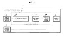
- Fig. 1 is a block diagram representing a schematic configuration of an illumination apparatus 1 for vehicle in a first embodiment of the invention.
- the illumination apparatus 1 for vehicle is mounted in a vehicle such as a four-wheel vehicle or a two-wheel vehicle which is ridden by a person and moves.
- the illumination apparatus 1 for vehicle includes a vehicle periphery detection section 2, a vehicle operation detection section 3, an illumination section 4 and an illumination control section 10.
- the vehicle periphery detection section 2 detects a pedestrian, a bicycle, an oncoming car, a forward running car, a sign, an indication, a traffic signal, etc. which are an object of traffic environment in the periphery of a vehicle.
- the vehicle periphery detection section 2 is constructed by an image sensor, and acquires an image.
- the vehicle periphery detection section 2 may be implemented by a radar, a laser, etc. as long as an image similar to the image sensor can be acquired.
- the vehicle operation detection section 3 acquires a speed of its own vehicle, a steering angle of a steering and information about inclination (angular speed sensor) of the vehicle.
- the illumination section 4 irradiates the periphery of its own vehicle and the front of its own vehicle with light.
- a light source may be implemented by halogen, an LED (Light Emitting Diode), organic EL (Electro Luminescence), etc. and as long as a particular place and only the particular place can be irradiated with toned light, any implementation device may be used.
- a concrete configuration example of the illumination section 4 will be described below.
- the illumination control section 10 performs control so as to be irradiated with light toned based on a shape of the object of the traffic environment, and includes a color estimation section 15, a light toning section 13 and a light irradiation range control section 14.
- the color estimation section 15 estimates a color of the object of the traffic environment detected by the vehicle periphery detection section 2. Concretely, the color estimation section 15 estimates the color of each object every position of the object of traffic environment from an image outputted from the vehicle periphery detection section 2.
- the light toning section 13 changes all or any of illuminance, luminance and color temperature K (kelvin) of light according to the color of the object of the traffic environment estimated by the color estimation section 15.
- the light irradiation range control section 14 controls an irradiation range of the light toned based on a position to the object of the traffic environment, the inclination, the steering angle and the vehicle speed acquired by the vehicle operation detection section 3.
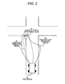
- Fig. 2 is an outline diagram explaining an operation outline of the illumination apparatus 1 for vehicle of the present embodiment.
- An example in which the illumination apparatus 1 for vehicle mounted in its own vehicle 24 irradiates the front including a road sign 21 with light at night is shown.
- the illumination apparatus 1 for vehicle mounted in its own vehicle 24 normally irradiates a headlight light irradiation region 23 with light.
- the illumination apparatus 1 for vehicle detects the object (sign) 21 of the traffic environment by the vehicle periphery detection section 2
- a color of the object 21 is estimated by the color estimation section 15.
- the light is toned according to the color of the object 21 by the light toning section 13 and an irradiation range 22 is decided with reference to an output of the vehicle operation detection section 3 by the light irradiation range control section 14 and the illumination section 4 irradiates the object 21 of traffic environment with toned light. That is, the illumination apparatus 1 for vehicle irradiates a region (toned light irradiation region) 22 including the object 21 of traffic environment among the headlight light irradiation region 23 with the toned light.
- the illumination apparatus 1 for vehicle of the embodiment thus, when the object 21 of traffic environment is detected, the light is toned according to the color of the object 21, and the object 21 of traffic environment is irradiated with the toned light, so that the object 21 can be irradiated so that the object 21 is most noticeable.
- Fig. 3 shows a concrete configuration example of the illumination section 4 in the illumination apparatus 1 for vehicle of the embodiment.
- the illumination section 4 uses an LED headlamp capable of surface emission, and an LED can perform toning control every element.
- right and left LED headlamps are respectively divided into six regions and toned light and its irradiation range are controlled every each region.
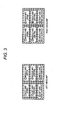
- Fig. 4 shows an example of a toned light irradiation range and a headlamp in the illumination apparatus 1 for vehicle of the embodiment.
- the left headlamp is divided into (1) a left and upper region, (2) a middle and upper region, (3) a left and central region, (4) a middle and central region, (5) a left and road surface region and (6) a middle and road surface region and is controlled and irradiates the regions of (1) to (6) of the front of a vehicle.
- the right headlamp is similarly divided into (7) a middle and upper region, (8) a right and upper region, (9) a middle and central region, (10) a right and central region, (11) a middle and road surface region and (12) a right and road surface region and is controlled and irradiates the regions of (7) to (12) of the front of the vehicle.
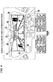
- Fig. 5 shows an example of a color and a toned light irradiation range in the illumination apparatus 1 for vehicle of the embodiment.
- objects of traffic environment such as a bicycle, a pedestrian, a sign and an oncoming vehicle are present in the front of a vehicle.
- the illumination apparatus 1 for vehicle irradiates the regions with light in which, for example, (1) the left and upper region, (2) the middle and upper region, (3) the left and central region, (4) the middle and central region, (7) the middle and upper region, (8) the right and upper region, (9) the middle and central region and (10) the right and central region are toned as a white color and (5) the left and road surface region, (6) the central and road surface region, (11) the middle and road surface region and (12) the right and road surface region are toned as a blue-white color according to colors of the objects of traffic environment.
- a color of an object of traffic environment detected is estimated and light is toned based on the color of the object estimated and an irradiation range of the light toned is controlled and the object of traffic environment is irradiated with the toned light from its own vehicle, so that visibility of a driver with respect to the object of traffic environment of the periphery of the vehicle can be improved at night etc. and an obstacle can be found early.
- Fig. 6 is a block diagram representing a schematic configuration of an illumination apparatus 1 for vehicle in a second embodiment of the invention.
- the illumination apparatus 1 for vehicle differs from the illumination apparatus 1 for vehicle shown in Fig. 1 in a configuration of an illumination control section 10.
- the illumination control section 10 includes an object shape extraction section 11, an object color determination section 12, a light toning section 13 and a light irradiation range control section 14. That is, the object shape extraction section 11 and the object color determination section 12 shown in Fig. 6 correspond to the color estimation section 15 shown in Fig. 1 , and estimate a color of an object of traffic environment detected by a vehicle periphery detection section 2.
- the object shape extraction section 11 extracts a shape of an object from an image acquired by an image sensor of the vehicle periphery detection section 2.
- the object color determination section 12 determines a color of an object based on the shape of the object acquired. Concretely, the object color determination section 12 determines the object color based on, for example, a table for storing correspondence between a color and the time and date and a place for a pedestrian and correspondence between a color and a shape for a sign according to a kind of the object detected by the object shape extraction section 11.
- the light toning section 13 changes all or any of illuminance, luminance and color temperature K (kelvin) of light according to a color of an object of traffic environment.
- the light irradiation range control section 14 controls an irradiation range of light toned based on a position to an object of traffic environment, inclination, a steering angle and a vehicle speed acquired by a vehicle operation detection section 3.
- Fig. 7 is a flowchart explaining an operation outline of the illumination control section 10 in the illumination apparatus 1 for vehicle of the embodiment.
- the operation outline of the illumination control section 10 will hereinafter be described by taking the case where an object of traffic environment is a road sign as an example.
- the vehicle periphery detection section 2 acquires an image of an object of traffic environment in the periphery of a vehicle (S301).
- the object shape extraction section 11 acquires and determines a shape of the object based on the image of the object acquired (S302).
- the road sign includes a regulatory sign, a warning sign and an indication sign, and the shapes are respectively different. Also, its color is different by a kind of sign.
- the object color determination section 12 determines that the color of the object with the regulatory sign is red when a shape of the sign is a circle or a downward triangular shape (S303), and determines that the color of the object with the warning sign is yellow when a shape of the sign is a rhombic shape (S304), and determines that the color of the object with the indication sign is blue when a shape of the sign is a quadrangular shape (S305).
- the object color determination section 12 can determine the object color based on, for example, a table for storing correspondence between a color and the time and date and a place for a pedestrian and correspondence between a color and a shape for a sign. Also, the object color determination section 12 may, for example, associate a color with a shape of a vehicle and determine that the color is red when the vehicle is a sports car.
- the light toning section 13 and an illumination section 4 irradiate the object with a high-intensity light source having good color rendering properties with color temperature slightly lower than that of light at the time of normal irradiation, that is, light with which the periphery of the object is irradiated and thereby, a red color of the object is vividly visible and visibility of a driver improves (S306).
- the object is yellow, the object is irradiated with a high-intensity light source having good color rendering properties with color temperature slightly lower than that of the periphery of the object and thereby, a yellow color of the object is vividly visible and visibility of a driver improves (S307).
- the object When the object is blue, the object is irradiated with a high-intensity light source having good color rendering properties with color temperature slightly higher than that of the periphery and thereby, a blue color of the object is vividly visible and visibility of a driver improves (S308). This is because the red color and yellow color of the object color are vividly visible when the object is irradiated with the high-intensity light source having good color rendering properties with color temperature slightly lower than that of the periphery.
- the light irradiation range control section 14 controls an irradiation range of light based on an object position of traffic environment, inclination, a steering angle and a vehicle speed of its own vehicle (S309).
- a speed of its own vehicle is quick, the irradiation range of light is moved quickly with respect to an object of traffic environment.
- the speed of its own vehicle is slow, the irradiation range of light is moved slowly with respect to the object of traffic environment.
- a shape of an object is extracted based on the object detected and a color of the object is determined based on the shape of the object extracted, so that the object can be irradiated with light toned according to the color of the object of traffic environment even in the case of being difficult to directly detect the color of the object, for example, at the time of a rainfall at night.
- an object of traffic environment is a road traffic sign
- a pedestrian, a bicycle, a two-wheel vehicle, a vehicle, road indication or a traffic signal are also targeted as the object of traffic environment for the invention.
- the whole pedestrian and a pedestrian partially hiding by a guardrail etc. are targeted.
- the bicycle and the two-wheel vehicle the whole pedestrian driving the bicycle or the two-wheel vehicle, a bicycle partially hiding by a guardrail etc. and a pedestrian driving the two-wheel vehicle are also targeted.
- a four-wheel vehicle such as a big car, a wagon, a sports car and a normal passenger car are targeted.
- a vehicular lane, a passing lane, a crosswalk, etc. are targeted.
- a color of an object can be determined from the time and date and a place. For example, when a color of an object cannot be acquired from an image acquired by the vehicle periphery detection section 2 and a shape of the object, it may be determined that a pedestrian often wears black clothes for winter, and a color of clothes of a pedestrian may be determined based on the fact that a favorite color of clothes varies depending on countries and regions.
- the invention has an effect capable of improving visibility of a driver with respect to an object of traffic environment of the periphery of a vehicle, and can be used as an illumination apparatus for vehicle.
Applications Claiming Priority (2)
| Application Number | Priority Date | Filing Date | Title |
|---|---|---|---|
| JP2007283824A JP2009107543A (ja) | 2007-10-31 | 2007-10-31 | 車両用照明装置 |
| PCT/JP2008/002772 WO2009057248A1 (ja) | 2007-10-31 | 2008-10-02 | 車両用照明装置 |
Publications (1)
| Publication Number | Publication Date |
|---|---|
| EP2213512A1 true EP2213512A1 (en) | 2010-08-04 |
Family
ID=40590655
Family Applications (1)
| Application Number | Title | Priority Date | Filing Date |
|---|---|---|---|
| EP08843583A Withdrawn EP2213512A1 (en) | 2007-10-31 | 2008-10-02 | Vehicular lighting device |
Country Status (5)
| Country | Link |
|---|---|
| US (1) | US20100235040A1 (ja) |
| EP (1) | EP2213512A1 (ja) |
| JP (1) | JP2009107543A (ja) |
| CN (1) | CN101842261A (ja) |
| WO (1) | WO2009057248A1 (ja) |
Cited By (8)
| Publication number | Priority date | Publication date | Assignee | Title |
|---|---|---|---|---|
| EP2340965A1 (en) * | 2009-12-08 | 2011-07-06 | Koito Manufacturing Co., Ltd. | Vehicle headlamp |
| DE102013001286A1 (de) * | 2013-01-25 | 2014-07-31 | GM Global Technology Operations LLC (n. d. Ges. d. Staates Delaware) | Scheinwerfersystem für ein Kraftfahrzeug |
| DE102013001259A1 (de) * | 2013-01-25 | 2014-07-31 | GM Global Technology Operations LLC (n. d. Gesetzen des Staates Delaware) | Leuchtensystem für ein Kraftfahrzeug |
| DE102013002211A1 (de) * | 2013-02-06 | 2014-08-07 | GM Global Technology Operations LLC (n. d. Ges. d. Staates Delaware) | Scheinwerfersystem für ein Kraftfahrzeug |
| DE102013016276A1 (de) * | 2013-09-28 | 2015-04-02 | GM GLOBAL TECHNOLOGY OPERATION LLC (n. d. Ges. d. Staates Delaware) | Scheinwerfer für ein Fahrzeug |
| EP2636560A4 (en) * | 2010-11-01 | 2015-07-08 | Adc Technology Inc | SPOTLIGHT CONTROL DEVICE |
| EP2927051A1 (fr) * | 2014-04-01 | 2015-10-07 | Valeo Vision | Eclairage à couleur adaptative |
| EP3421669A1 (en) * | 2017-06-29 | 2019-01-02 | Honda Motor Co., Ltd. | Working machine |
Families Citing this family (21)
| Publication number | Priority date | Publication date | Assignee | Title |
|---|---|---|---|---|
| JP2011209019A (ja) * | 2010-03-29 | 2011-10-20 | Sony Corp | ロボット装置及びロボット装置の制御方法 |
| JP5392174B2 (ja) * | 2010-04-28 | 2014-01-22 | スタンレー電気株式会社 | 車両用灯具 |
| JP5392175B2 (ja) * | 2010-04-28 | 2014-01-22 | スタンレー電気株式会社 | 車両用灯具 |
| CN103582906B (zh) * | 2011-06-02 | 2016-01-20 | 丰田自动车株式会社 | 车辆用视野辅助装置 |
| CN103057459B (zh) * | 2011-10-19 | 2017-06-13 | 现代摩比斯株式会社 | 车用灯具及其控制方法 |
| DE102011118332A1 (de) * | 2011-11-11 | 2013-05-16 | GM Global Technology Operations LLC (n. d. Gesetzen des Staates Delaware) | Beleuchtungsvorrichtung eines Fahrzeugs |
| JP5696701B2 (ja) * | 2012-08-31 | 2015-04-08 | 株式会社デンソー | 対歩行者報知装置 |
| DE102013210097A1 (de) * | 2013-05-29 | 2014-12-04 | Robert Bosch Gmbh | Fahrerinformationseinrichtung |
| CN103481812B (zh) * | 2013-10-16 | 2016-06-29 | 北京大学东莞光电研究院 | 激光与钨丝灯混合光源汽车大灯 |
| JP6327999B2 (ja) * | 2014-08-04 | 2018-05-23 | 株式会社小糸製作所 | 車両用灯具 |
| KR102227371B1 (ko) * | 2014-09-19 | 2021-03-11 | 엘지전자 주식회사 | 차량용 영상투사장치 및 이를 구비한 차량 |
| DE102016121071A1 (de) * | 2015-11-04 | 2017-05-04 | GM Global Technology Operations LLC (n. d. Ges. d. Staates Delaware) | Fahrzeugbeleuchtungssystem, das einem benutzer folgt |
| KR101830664B1 (ko) * | 2016-07-08 | 2018-02-21 | 엘지전자 주식회사 | 차량에 구비된 제어장치 및 이의 제어방법 |
| US20180186278A1 (en) * | 2016-08-30 | 2018-07-05 | Faraday&Future Inc. | Smart beam lights for driving and environment assistance |
| JP2018055895A (ja) * | 2016-09-27 | 2018-04-05 | パナソニックIpマネジメント株式会社 | 車両用前照灯 |
| CN113232647A (zh) * | 2016-12-07 | 2021-08-10 | 厦门大学 | 一种车前物体识别方法及其识别装置 |
| CN109131040A (zh) * | 2017-06-17 | 2019-01-04 | 深圳市绎立锐光科技开发有限公司 | 动态大灯系统及其控制方法、车辆 |
| JP2020035241A (ja) * | 2018-08-30 | 2020-03-05 | Zホールディングス株式会社 | 通知装置、通知方法および通知プログラム |
| KR20210015448A (ko) * | 2019-08-02 | 2021-02-10 | 현대자동차주식회사 | 차량의 조도 정보 생성 장치 및 방법 |
| CN113459938B (zh) * | 2021-07-06 | 2022-02-22 | 江苏鑫蕴模塑科技有限公司 | 车灯增强识别系统及方法 |
| CN113473681A (zh) * | 2021-07-30 | 2021-10-01 | 重庆长安新能源汽车科技有限公司 | 一种迎宾控制系统、方法及汽车 |
Family Cites Families (11)
| Publication number | Priority date | Publication date | Assignee | Title |
|---|---|---|---|---|
| JP2921404B2 (ja) | 1993-08-20 | 1999-07-19 | トヨタ自動車株式会社 | 車両用前照灯装置 |
| JP3006471B2 (ja) * | 1996-01-08 | 2000-02-07 | 三菱自動車工業株式会社 | 標識の認識方法 |
| JP2003072461A (ja) * | 2001-08-31 | 2003-03-12 | Denso Corp | 車両用前照灯光軸方向自動調整装置 |
| JP4253271B2 (ja) * | 2003-08-11 | 2009-04-08 | 株式会社日立製作所 | 画像処理システム及び車両制御システム |
| JP4253275B2 (ja) * | 2003-08-11 | 2009-04-08 | 株式会社日立製作所 | 車両制御システム |
| JP4333419B2 (ja) * | 2004-03-12 | 2009-09-16 | 市光工業株式会社 | 車両用前照灯システム |
| JP4367232B2 (ja) * | 2004-05-20 | 2009-11-18 | トヨタ自動車株式会社 | 車両用照灯装置 |
| JP2006252264A (ja) * | 2005-03-11 | 2006-09-21 | Omron Corp | 障害物報知装置 |
| JP2006290007A (ja) * | 2005-04-05 | 2006-10-26 | Ichikoh Ind Ltd | 車両用警告灯装置 |
| JP4534871B2 (ja) * | 2005-05-25 | 2010-09-01 | 株式会社デンソー | 車両用照明装置 |
| JP4771055B2 (ja) * | 2005-06-16 | 2011-09-14 | スタンレー電気株式会社 | 車両用灯具及びそのled光源 |
-
2007
- 2007-10-31 JP JP2007283824A patent/JP2009107543A/ja not_active Ceased
-
2008
- 2008-10-02 CN CN200880114126A patent/CN101842261A/zh active Pending
- 2008-10-02 US US12/740,006 patent/US20100235040A1/en not_active Abandoned
- 2008-10-02 EP EP08843583A patent/EP2213512A1/en not_active Withdrawn
- 2008-10-02 WO PCT/JP2008/002772 patent/WO2009057248A1/ja active Application Filing
Non-Patent Citations (1)
| Title |
|---|
| See references of WO2009057248A1 * |
Cited By (10)
| Publication number | Priority date | Publication date | Assignee | Title |
|---|---|---|---|---|
| EP2340965A1 (en) * | 2009-12-08 | 2011-07-06 | Koito Manufacturing Co., Ltd. | Vehicle headlamp |
| US8297815B2 (en) | 2009-12-08 | 2012-10-30 | Koito Manufacturing Co., Ltd. | Vehicle lamp |
| EP2636560A4 (en) * | 2010-11-01 | 2015-07-08 | Adc Technology Inc | SPOTLIGHT CONTROL DEVICE |
| DE102013001286A1 (de) * | 2013-01-25 | 2014-07-31 | GM Global Technology Operations LLC (n. d. Ges. d. Staates Delaware) | Scheinwerfersystem für ein Kraftfahrzeug |
| DE102013001259A1 (de) * | 2013-01-25 | 2014-07-31 | GM Global Technology Operations LLC (n. d. Gesetzen des Staates Delaware) | Leuchtensystem für ein Kraftfahrzeug |
| DE102013002211A1 (de) * | 2013-02-06 | 2014-08-07 | GM Global Technology Operations LLC (n. d. Ges. d. Staates Delaware) | Scheinwerfersystem für ein Kraftfahrzeug |
| DE102013016276A1 (de) * | 2013-09-28 | 2015-04-02 | GM GLOBAL TECHNOLOGY OPERATION LLC (n. d. Ges. d. Staates Delaware) | Scheinwerfer für ein Fahrzeug |
| EP2927051A1 (fr) * | 2014-04-01 | 2015-10-07 | Valeo Vision | Eclairage à couleur adaptative |
| EP3421669A1 (en) * | 2017-06-29 | 2019-01-02 | Honda Motor Co., Ltd. | Working machine |
| US11178738B2 (en) | 2017-06-29 | 2021-11-16 | Honda Motor Co., Ltd. | Working machine |
Also Published As
| Publication number | Publication date |
|---|---|
| US20100235040A1 (en) | 2010-09-16 |
| WO2009057248A1 (ja) | 2009-05-07 |
| JP2009107543A (ja) | 2009-05-21 |
| CN101842261A (zh) | 2010-09-22 |
Similar Documents
| Publication | Publication Date | Title |
|---|---|---|
| EP2213512A1 (en) | Vehicular lighting device | |
| CN106794792B (zh) | 车辆用路面绘制系统 | |
| JP4964195B2 (ja) | 車両用照明装置 | |
| CN108569207B (zh) | 图像显示装置 | |
| López et al. | Nighttime vehicle detection for intelligent headlight control | |
| US8543254B1 (en) | Vehicular imaging system and method for determining roadway width | |
| JP6465318B2 (ja) | 画像表示装置 | |
| CN112770939A (zh) | 灯具系统及车辆用灯具 | |
| US9102265B2 (en) | Method and device for the distance-based debouncing of light-characteristic changes | |
| US9821704B2 (en) | Device and method for controlling a headlamp of a motor vehicle | |
| US10493902B2 (en) | Vehicle lighting system | |
| CN110869940B (zh) | 控制位于行车道上的机动车的像素大灯的方法 | |
| CN103373299A (zh) | 车辆安全照明设备和方法 | |
| JP5361901B2 (ja) | 前照灯制御装置 | |
| JP2020055374A (ja) | 自動車用照明灯 | |
| JP2013097885A (ja) | ヘッドライト装置、及びヘッドライトシステム | |
| EP4029733A1 (en) | Drawing device for vehicles | |
| JP2010052527A (ja) | 道路照明制御装置および道路照明制御システム | |
| KR20140111733A (ko) | 매트릭스형 스마트 자동차 전조등 | |
| JP5097651B2 (ja) | 道路照明制御装置および道路照明制御システム | |
| KR20160091331A (ko) | 자동차용 야간 화상들을 형성하는 시스템 및 방법 | |
| KR20190123522A (ko) | 도로 마킹 조명 장치 | |
| KR20190052741A (ko) | 횡단보도 안전선표시장치 | |
| KR20130136107A (ko) | 자동차 | |
| KR20220026403A (ko) | 차량용 램프의 제어 장치 |
Legal Events
| Date | Code | Title | Description |
|---|---|---|---|
| PUAI | Public reference made under article 153(3) epc to a published international application that has entered the european phase |
Free format text: ORIGINAL CODE: 0009012 |
|
| 17P | Request for examination filed |
Effective date: 20100429 |
|
| AK | Designated contracting states |
Kind code of ref document: A1 Designated state(s): AT BE BG CH CY CZ DE DK EE ES FI FR GB GR HR HU IE IS IT LI LT LU LV MC MT NL NO PL PT RO SE SI SK TR |
|
| AX | Request for extension of the european patent |
Extension state: AL BA MK RS |
|
| DAX | Request for extension of the european patent (deleted) | ||
| STAA | Information on the status of an ep patent application or granted ep patent |
Free format text: STATUS: THE APPLICATION HAS BEEN WITHDRAWN |
|
| 18W | Application withdrawn |
Effective date: 20120629 |