EP2199136A1 - Energieübertragungsvorrichtung - Google Patents
Energieübertragungsvorrichtung Download PDFInfo
- Publication number
- EP2199136A1 EP2199136A1 EP08839641A EP08839641A EP2199136A1 EP 2199136 A1 EP2199136 A1 EP 2199136A1 EP 08839641 A EP08839641 A EP 08839641A EP 08839641 A EP08839641 A EP 08839641A EP 2199136 A1 EP2199136 A1 EP 2199136A1
- Authority
- EP
- European Patent Office
- Prior art keywords
- rotary
- shaft
- gear
- power
- speed
- Prior art date
- Legal status (The legal status is an assumption and is not a legal conclusion. Google has not performed a legal analysis and makes no representation as to the accuracy of the status listed.)
- Withdrawn
Links
Images


Classifications
-
- B—PERFORMING OPERATIONS; TRANSPORTING
- B60—VEHICLES IN GENERAL
- B60K—ARRANGEMENT OR MOUNTING OF PROPULSION UNITS OR OF TRANSMISSIONS IN VEHICLES; ARRANGEMENT OR MOUNTING OF PLURAL DIVERSE PRIME-MOVERS IN VEHICLES; AUXILIARY DRIVES FOR VEHICLES; INSTRUMENTATION OR DASHBOARDS FOR VEHICLES; ARRANGEMENTS IN CONNECTION WITH COOLING, AIR INTAKE, GAS EXHAUST OR FUEL SUPPLY OF PROPULSION UNITS IN VEHICLES
- B60K6/00—Arrangement or mounting of plural diverse prime-movers for mutual or common propulsion, e.g. hybrid propulsion systems comprising electric motors and internal combustion engines
- B60K6/20—Arrangement or mounting of plural diverse prime-movers for mutual or common propulsion, e.g. hybrid propulsion systems comprising electric motors and internal combustion engines the prime-movers consisting of electric motors and internal combustion engines, e.g. HEVs
- B60K6/42—Arrangement or mounting of plural diverse prime-movers for mutual or common propulsion, e.g. hybrid propulsion systems comprising electric motors and internal combustion engines the prime-movers consisting of electric motors and internal combustion engines, e.g. HEVs characterised by the architecture of the hybrid electric vehicle
- B60K6/48—Parallel type
-
- B—PERFORMING OPERATIONS; TRANSPORTING
- B60—VEHICLES IN GENERAL
- B60K—ARRANGEMENT OR MOUNTING OF PROPULSION UNITS OR OF TRANSMISSIONS IN VEHICLES; ARRANGEMENT OR MOUNTING OF PLURAL DIVERSE PRIME-MOVERS IN VEHICLES; AUXILIARY DRIVES FOR VEHICLES; INSTRUMENTATION OR DASHBOARDS FOR VEHICLES; ARRANGEMENTS IN CONNECTION WITH COOLING, AIR INTAKE, GAS EXHAUST OR FUEL SUPPLY OF PROPULSION UNITS IN VEHICLES
- B60K6/00—Arrangement or mounting of plural diverse prime-movers for mutual or common propulsion, e.g. hybrid propulsion systems comprising electric motors and internal combustion engines
- B60K6/20—Arrangement or mounting of plural diverse prime-movers for mutual or common propulsion, e.g. hybrid propulsion systems comprising electric motors and internal combustion engines the prime-movers consisting of electric motors and internal combustion engines, e.g. HEVs
- B60K6/22—Arrangement or mounting of plural diverse prime-movers for mutual or common propulsion, e.g. hybrid propulsion systems comprising electric motors and internal combustion engines the prime-movers consisting of electric motors and internal combustion engines, e.g. HEVs characterised by apparatus, components or means specially adapted for HEVs
- B60K6/26—Arrangement or mounting of plural diverse prime-movers for mutual or common propulsion, e.g. hybrid propulsion systems comprising electric motors and internal combustion engines the prime-movers consisting of electric motors and internal combustion engines, e.g. HEVs characterised by apparatus, components or means specially adapted for HEVs characterised by the motors or the generators
-
- B—PERFORMING OPERATIONS; TRANSPORTING
- B60—VEHICLES IN GENERAL
- B60K—ARRANGEMENT OR MOUNTING OF PROPULSION UNITS OR OF TRANSMISSIONS IN VEHICLES; ARRANGEMENT OR MOUNTING OF PLURAL DIVERSE PRIME-MOVERS IN VEHICLES; AUXILIARY DRIVES FOR VEHICLES; INSTRUMENTATION OR DASHBOARDS FOR VEHICLES; ARRANGEMENTS IN CONNECTION WITH COOLING, AIR INTAKE, GAS EXHAUST OR FUEL SUPPLY OF PROPULSION UNITS IN VEHICLES
- B60K6/00—Arrangement or mounting of plural diverse prime-movers for mutual or common propulsion, e.g. hybrid propulsion systems comprising electric motors and internal combustion engines
- B60K6/20—Arrangement or mounting of plural diverse prime-movers for mutual or common propulsion, e.g. hybrid propulsion systems comprising electric motors and internal combustion engines the prime-movers consisting of electric motors and internal combustion engines, e.g. HEVs
- B60K6/22—Arrangement or mounting of plural diverse prime-movers for mutual or common propulsion, e.g. hybrid propulsion systems comprising electric motors and internal combustion engines the prime-movers consisting of electric motors and internal combustion engines, e.g. HEVs characterised by apparatus, components or means specially adapted for HEVs
- B60K6/36—Arrangement or mounting of plural diverse prime-movers for mutual or common propulsion, e.g. hybrid propulsion systems comprising electric motors and internal combustion engines the prime-movers consisting of electric motors and internal combustion engines, e.g. HEVs characterised by apparatus, components or means specially adapted for HEVs characterised by the transmission gearings
- B60K6/365—Arrangement or mounting of plural diverse prime-movers for mutual or common propulsion, e.g. hybrid propulsion systems comprising electric motors and internal combustion engines the prime-movers consisting of electric motors and internal combustion engines, e.g. HEVs characterised by apparatus, components or means specially adapted for HEVs characterised by the transmission gearings with the gears having orbital motion
-
- B—PERFORMING OPERATIONS; TRANSPORTING
- B60—VEHICLES IN GENERAL
- B60K—ARRANGEMENT OR MOUNTING OF PROPULSION UNITS OR OF TRANSMISSIONS IN VEHICLES; ARRANGEMENT OR MOUNTING OF PLURAL DIVERSE PRIME-MOVERS IN VEHICLES; AUXILIARY DRIVES FOR VEHICLES; INSTRUMENTATION OR DASHBOARDS FOR VEHICLES; ARRANGEMENTS IN CONNECTION WITH COOLING, AIR INTAKE, GAS EXHAUST OR FUEL SUPPLY OF PROPULSION UNITS IN VEHICLES
- B60K6/00—Arrangement or mounting of plural diverse prime-movers for mutual or common propulsion, e.g. hybrid propulsion systems comprising electric motors and internal combustion engines
- B60K6/20—Arrangement or mounting of plural diverse prime-movers for mutual or common propulsion, e.g. hybrid propulsion systems comprising electric motors and internal combustion engines the prime-movers consisting of electric motors and internal combustion engines, e.g. HEVs
- B60K6/22—Arrangement or mounting of plural diverse prime-movers for mutual or common propulsion, e.g. hybrid propulsion systems comprising electric motors and internal combustion engines the prime-movers consisting of electric motors and internal combustion engines, e.g. HEVs characterised by apparatus, components or means specially adapted for HEVs
- B60K6/40—Arrangement or mounting of plural diverse prime-movers for mutual or common propulsion, e.g. hybrid propulsion systems comprising electric motors and internal combustion engines the prime-movers consisting of electric motors and internal combustion engines, e.g. HEVs characterised by apparatus, components or means specially adapted for HEVs characterised by the assembly or relative disposition of components
- B60K6/405—Housings
-
- B—PERFORMING OPERATIONS; TRANSPORTING
- B60—VEHICLES IN GENERAL
- B60K—ARRANGEMENT OR MOUNTING OF PROPULSION UNITS OR OF TRANSMISSIONS IN VEHICLES; ARRANGEMENT OR MOUNTING OF PLURAL DIVERSE PRIME-MOVERS IN VEHICLES; AUXILIARY DRIVES FOR VEHICLES; INSTRUMENTATION OR DASHBOARDS FOR VEHICLES; ARRANGEMENTS IN CONNECTION WITH COOLING, AIR INTAKE, GAS EXHAUST OR FUEL SUPPLY OF PROPULSION UNITS IN VEHICLES
- B60K6/00—Arrangement or mounting of plural diverse prime-movers for mutual or common propulsion, e.g. hybrid propulsion systems comprising electric motors and internal combustion engines
- B60K6/20—Arrangement or mounting of plural diverse prime-movers for mutual or common propulsion, e.g. hybrid propulsion systems comprising electric motors and internal combustion engines the prime-movers consisting of electric motors and internal combustion engines, e.g. HEVs
- B60K6/50—Architecture of the driveline characterised by arrangement or kind of transmission units
- B60K6/54—Transmission for changing ratio
- B60K6/547—Transmission for changing ratio the transmission being a stepped gearing
-
- F—MECHANICAL ENGINEERING; LIGHTING; HEATING; WEAPONS; BLASTING
- F16—ENGINEERING ELEMENTS AND UNITS; GENERAL MEASURES FOR PRODUCING AND MAINTAINING EFFECTIVE FUNCTIONING OF MACHINES OR INSTALLATIONS; THERMAL INSULATION IN GENERAL
- F16H—GEARING
- F16H3/00—Toothed gearings for conveying rotary motion with variable gear ratio or for reversing rotary motion
- F16H3/02—Toothed gearings for conveying rotary motion with variable gear ratio or for reversing rotary motion without gears having orbital motion
- F16H3/08—Toothed gearings for conveying rotary motion with variable gear ratio or for reversing rotary motion without gears having orbital motion exclusively or essentially with continuously meshing gears, that can be disengaged from their shafts
- F16H3/12—Toothed gearings for conveying rotary motion with variable gear ratio or for reversing rotary motion without gears having orbital motion exclusively or essentially with continuously meshing gears, that can be disengaged from their shafts with means for synchronisation not incorporated in the clutches
- F16H3/126—Toothed gearings for conveying rotary motion with variable gear ratio or for reversing rotary motion without gears having orbital motion exclusively or essentially with continuously meshing gears, that can be disengaged from their shafts with means for synchronisation not incorporated in the clutches using an electric drive
-
- B—PERFORMING OPERATIONS; TRANSPORTING
- B60—VEHICLES IN GENERAL
- B60K—ARRANGEMENT OR MOUNTING OF PROPULSION UNITS OR OF TRANSMISSIONS IN VEHICLES; ARRANGEMENT OR MOUNTING OF PLURAL DIVERSE PRIME-MOVERS IN VEHICLES; AUXILIARY DRIVES FOR VEHICLES; INSTRUMENTATION OR DASHBOARDS FOR VEHICLES; ARRANGEMENTS IN CONNECTION WITH COOLING, AIR INTAKE, GAS EXHAUST OR FUEL SUPPLY OF PROPULSION UNITS IN VEHICLES
- B60K6/00—Arrangement or mounting of plural diverse prime-movers for mutual or common propulsion, e.g. hybrid propulsion systems comprising electric motors and internal combustion engines
- B60K6/20—Arrangement or mounting of plural diverse prime-movers for mutual or common propulsion, e.g. hybrid propulsion systems comprising electric motors and internal combustion engines the prime-movers consisting of electric motors and internal combustion engines, e.g. HEVs
- B60K6/42—Arrangement or mounting of plural diverse prime-movers for mutual or common propulsion, e.g. hybrid propulsion systems comprising electric motors and internal combustion engines the prime-movers consisting of electric motors and internal combustion engines, e.g. HEVs characterised by the architecture of the hybrid electric vehicle
- B60K6/48—Parallel type
- B60K2006/4808—Electric machine connected or connectable to gearbox output shaft
-
- B—PERFORMING OPERATIONS; TRANSPORTING
- B60—VEHICLES IN GENERAL
- B60K—ARRANGEMENT OR MOUNTING OF PROPULSION UNITS OR OF TRANSMISSIONS IN VEHICLES; ARRANGEMENT OR MOUNTING OF PLURAL DIVERSE PRIME-MOVERS IN VEHICLES; AUXILIARY DRIVES FOR VEHICLES; INSTRUMENTATION OR DASHBOARDS FOR VEHICLES; ARRANGEMENTS IN CONNECTION WITH COOLING, AIR INTAKE, GAS EXHAUST OR FUEL SUPPLY OF PROPULSION UNITS IN VEHICLES
- B60K6/00—Arrangement or mounting of plural diverse prime-movers for mutual or common propulsion, e.g. hybrid propulsion systems comprising electric motors and internal combustion engines
- B60K6/20—Arrangement or mounting of plural diverse prime-movers for mutual or common propulsion, e.g. hybrid propulsion systems comprising electric motors and internal combustion engines the prime-movers consisting of electric motors and internal combustion engines, e.g. HEVs
- B60K6/42—Arrangement or mounting of plural diverse prime-movers for mutual or common propulsion, e.g. hybrid propulsion systems comprising electric motors and internal combustion engines the prime-movers consisting of electric motors and internal combustion engines, e.g. HEVs characterised by the architecture of the hybrid electric vehicle
- B60K6/48—Parallel type
- B60K2006/4825—Electric machine connected or connectable to gearbox input shaft
-
- B—PERFORMING OPERATIONS; TRANSPORTING
- B60—VEHICLES IN GENERAL
- B60K—ARRANGEMENT OR MOUNTING OF PROPULSION UNITS OR OF TRANSMISSIONS IN VEHICLES; ARRANGEMENT OR MOUNTING OF PLURAL DIVERSE PRIME-MOVERS IN VEHICLES; AUXILIARY DRIVES FOR VEHICLES; INSTRUMENTATION OR DASHBOARDS FOR VEHICLES; ARRANGEMENTS IN CONNECTION WITH COOLING, AIR INTAKE, GAS EXHAUST OR FUEL SUPPLY OF PROPULSION UNITS IN VEHICLES
- B60K6/00—Arrangement or mounting of plural diverse prime-movers for mutual or common propulsion, e.g. hybrid propulsion systems comprising electric motors and internal combustion engines
- B60K6/20—Arrangement or mounting of plural diverse prime-movers for mutual or common propulsion, e.g. hybrid propulsion systems comprising electric motors and internal combustion engines the prime-movers consisting of electric motors and internal combustion engines, e.g. HEVs
- B60K6/42—Arrangement or mounting of plural diverse prime-movers for mutual or common propulsion, e.g. hybrid propulsion systems comprising electric motors and internal combustion engines the prime-movers consisting of electric motors and internal combustion engines, e.g. HEVs characterised by the architecture of the hybrid electric vehicle
- B60K6/48—Parallel type
- B60K2006/4833—Step up or reduction gearing driving generator, e.g. to operate generator in most efficient speed range
-
- F—MECHANICAL ENGINEERING; LIGHTING; HEATING; WEAPONS; BLASTING
- F16—ENGINEERING ELEMENTS AND UNITS; GENERAL MEASURES FOR PRODUCING AND MAINTAINING EFFECTIVE FUNCTIONING OF MACHINES OR INSTALLATIONS; THERMAL INSULATION IN GENERAL
- F16H—GEARING
- F16H3/00—Toothed gearings for conveying rotary motion with variable gear ratio or for reversing rotary motion
- F16H3/02—Toothed gearings for conveying rotary motion with variable gear ratio or for reversing rotary motion without gears having orbital motion
- F16H3/08—Toothed gearings for conveying rotary motion with variable gear ratio or for reversing rotary motion without gears having orbital motion exclusively or essentially with continuously meshing gears, that can be disengaged from their shafts
- F16H3/087—Toothed gearings for conveying rotary motion with variable gear ratio or for reversing rotary motion without gears having orbital motion exclusively or essentially with continuously meshing gears, that can be disengaged from their shafts characterised by the disposition of the gears
- F16H3/091—Toothed gearings for conveying rotary motion with variable gear ratio or for reversing rotary motion without gears having orbital motion exclusively or essentially with continuously meshing gears, that can be disengaged from their shafts characterised by the disposition of the gears including a single countershaft
- F16H3/0915—Toothed gearings for conveying rotary motion with variable gear ratio or for reversing rotary motion without gears having orbital motion exclusively or essentially with continuously meshing gears, that can be disengaged from their shafts characterised by the disposition of the gears including a single countershaft with coaxial input and output shafts
-
- Y—GENERAL TAGGING OF NEW TECHNOLOGICAL DEVELOPMENTS; GENERAL TAGGING OF CROSS-SECTIONAL TECHNOLOGIES SPANNING OVER SEVERAL SECTIONS OF THE IPC; TECHNICAL SUBJECTS COVERED BY FORMER USPC CROSS-REFERENCE ART COLLECTIONS [XRACs] AND DIGESTS
- Y02—TECHNOLOGIES OR APPLICATIONS FOR MITIGATION OR ADAPTATION AGAINST CLIMATE CHANGE
- Y02T—CLIMATE CHANGE MITIGATION TECHNOLOGIES RELATED TO TRANSPORTATION
- Y02T10/00—Road transport of goods or passengers
- Y02T10/60—Other road transportation technologies with climate change mitigation effect
- Y02T10/62—Hybrid vehicles
-
- Y—GENERAL TAGGING OF NEW TECHNOLOGICAL DEVELOPMENTS; GENERAL TAGGING OF CROSS-SECTIONAL TECHNOLOGIES SPANNING OVER SEVERAL SECTIONS OF THE IPC; TECHNICAL SUBJECTS COVERED BY FORMER USPC CROSS-REFERENCE ART COLLECTIONS [XRACs] AND DIGESTS
- Y10—TECHNICAL SUBJECTS COVERED BY FORMER USPC
- Y10T—TECHNICAL SUBJECTS COVERED BY FORMER US CLASSIFICATION
- Y10T74/00—Machine element or mechanism
- Y10T74/19—Gearing
- Y10T74/19023—Plural power paths to and/or from gearing
- Y10T74/19074—Single drive plural driven
Definitions
- the present invention relates to a power transmission apparatusthatusesmanualchange-speed mechanism or automated manual change-speed mechanism; in particular, it relates to a power transmission apparatus for hybrid vehicle that has a rotary electric device additionally as the power source.
- hybrid vehicles have been developed, hybrid vehicles which have a motor additionally as the power source (Patent Literature No. 1).
- Patent Literature No. 1 In hybrid vehicles, it is feasible to intend the improvement of fuel consumption by utilizing revolution-speed ranges where the internal combustion engine and the motor exhibit good efficiency respectively, or by making use of them simultaneously.
- Patent Literature No. 1 Japanese Unexamined Patent Publication (KOKAI) Gazette No. 2000-224,710
- the present invention is one which has been done in view of the aforementioned assignments, and it is an assignment to provide a power transmission apparatus which neither gets complicated nor jumboized, whose cost does not go up, whose weight does not increase, and which can make use of motor upon starting internal combustion engine.
- a constructional characteristic of an invention that is directed to claim 1 lies in that it comprises:
- a constructional characteristic of an invention that is directed to claim 2 lies in that, in claim 1, a stator of said rotary electric device is positioned on an outer peripheral side of said rotor, and said rotor has a ring configuration; said output shaft of said internal combustion engine, said input shaft of said multistaged change-speed mechanism, said rotor of said rotary electric device, and a rotary shaft of said rotary-electric-device-side output shaft are all coaxial; and said first power interrupting mechanism, and said second power interrupting mechanism are disposed on an inner peripheral side of said rotor while lining up in an axial direction of said output shaft of said internal combustion engine.
- a constructional characteristic of an invention that is directed to claim 3 lies in that, in claim 1 or 2, said output shaft of said multistaged change-speed mechanism has an output gear that meshes with a final deceleration gear; said input shaft of said multistaged change-speed mechanism, and said output shaft thereof are disposed to protrude parallelly on a side of said rotary electric device; and said rotary-electric-device-side output shaft has a rotary-electric-device-side output gear for transmitting a rotary power to said final deceleration gear by way of said output gear.
- a constructional characteristic of an invention that is directed to claim 4 lies in that, in claim 1 or 2, said rotary-electric-device-side output shaft has a rotary-electric-device-side output gear; and the power transmission apparatus further comprises an additional shaft having a transmission gear that meshes with both of said rotary-electric-side output gear and said final deceleration gear between them, thereby transmitting a rotary power from said rotary-electric-side output gear to said final deceleration gear.
- a constructional characteristic of an invention that is directed to claim 5 lies in that, in either of claims 1-4, the power transmission apparatus has a planetary gear mechanism in which said rotary-electric-device-side output shaft is connected to one of the elements and said rotor of said rotary electric is disconnected from and connected to another one of the elements by way of said second power interrupting mechanism.
- said multistaged change-speed mechanism comprises a counter shaft; the rotary power of said internal combustion engine, and the rotary power of said rotary electric device are transmitted to said input shaft of said multistaged change-speed mechanism, and to said output shaft, by way of said counter shaft; said input shaft of said multistaged change-speed mechanism, and said counter shaft thereof are disposed to protrude parallelly on a side of said rotary electric device; said counter shaft has a rotary-electric-device-side input gear to which an output of said rotary electric device is input; and said rotary-electric-device-side output shaft has a rotary-electric-device-side output gear that meshes with said rotary-electric-device-side input gear.
- said multistaged change-speed mechanism comprises a counter shaft, and an additional shaft; the rotary power of said internal combustion engine, and the rotary power of said rotary electric device are transmitted to said input shaft of said multistaged change-speed mechanism, and to said output shaft, by way of said counter shaft; said input shaft of said multistaged change-speed mechanism, and said additional shaft thereof are disposed to protrude parallelly on a side of said rotary electric device; said rotary-electric-device-side output shaft has a rotary-electric-device-side output gear for transmitting the rotary power of said rotary electric device to a side of said output shaft; said output shaft has an additional-shaft-side input gear in order that the rotary power of said rotary electric device is transmitted by way of said additional shaft; and said additional shaft has an input-side transmission gear at one of the ends, input-side transmission gear which meshes with said rotary-electric-device-side output gear
- the rotary electric device is connected to an upstream side of the multistaged change-speed mechanism, and to a downstream side thereof, because a rotor of the rotary electric device can be connected to the input shaft of the multistaged change-speed mechanism (i.e., on the upstream side) by way of the first power interrupting mechanism, and because the rotary-electric-device-side output shaft can be connected to the rotor of the rotary electric device by way of the second power interrupting mechanism on an output-shaft side of the multistaged change-speed mechanism (i.e., on the downstream side).
- a power transmission apparatus with both of the following characteristics: it is possible to make use of the rotary electric device for starting the internal combustion engine when the rotary electric device is connected to the upstream side; and it is possible to make use of the rotary power, which is output from the rotary electric device, as a motive power without intervening the multistaged change-speed mechanism when it is connected to the downstream side; and the like. And, by sharing the starting of the internal combustion engine and the generation of electricity with the rotary electric device, it becomes feasible to downsize the starter and alternator, or to omit them, so that the costs can be suppressed.
- both of the first power interrupting mechanism and second power interrupting mechanism are disconnected, and then the giving and receiving of the motive power to and from the rotary electric device are turned off, and accordingly it is also possible to avoid the loss of electricity or driving force, and consequently it is possible to drive with good fuel-consumption performance depending on traveling conditions.
- the construction gets complicated in order to connect the rotor of the rotary electric device to a distant shaft because the rotor of the electric device gets away from one of the input and output shafts when it is close to the other one of them, it is possible to avoid the construction from getting complicated by means of disposing both of the shafts to protrude toward a side in the same direction.
- the construction does not get complicated, but it can be constructed compactly.
- the invention that is directed to claim 6, it further comprises a counter shaft other than the input shaft and output shaft, and the counter shaft is disposed to protrude toward a side of the rotary electric device along with the input shaft. And, an output of the rotary electric device can be input to the counter shaft, and can then be transmitted to the output shaft.
- it further comprises a counter shaft and an additional shaft other than the input shaft and output shaft, and the input shaft and additional shaft are disposed to protrude toward a side of the rotary electric device.
- An output from the rotary electric device can be transmitted to the output shaft.
- a power transmission apparatus that is directed to an embodying mode according to the present invention can be materialized by partially improving a power transmission apparatus into which a manual transmission is incorporated, manual transmission which serves as a multistaged change-speed mechanism (MT) that is boarded onto automobiles and that makes change-speed operations feasible by means of a driver's manual operations, for instance.
- MT multistaged change-speed mechanism
- AMT automated multistaged change-speed mechanisms
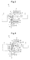
- a power transmission apparatus 10 As illustrated in Fig. 1 , a power transmission apparatus 10 according to Embodying Mode No. 1 comprises an internal combustion engine 2, a multistaged change-speed mechanism 3, a rotary electric device 4, a first power interrupting mechanism 51, a second power interrupting mechanism 52, and a controlling unit (not shown in the drawing).
- the power transmission apparatus 10 according to the present embodying mode is an apparatus for automobile onto which an internal combustion engine (not shown) is onboard in the front to drive the front wheels.
- the internal combustion engine 2 gasoline engines or diesel engines, and the like, can be named.
- the internal combustion engine is positioned on the side of an input 31 of the later-described multistaged change-speed mechanism 3 (i.e., on the upstream side), is connected to the input shaft 31 coaxially, and comprises an output shaft 21 that is connected to a rotor 42 of the later-described rotary electric device 4 by way of the later-described first power interrupting mechanism 51.
- the internal combustion engine 2 has a fuel supplying device, throttles for controlling an air supply amount, and the like, and their fuel and air supply amounts are controlled based on control signals from the outside.
- the internal combustion engine 2 has a revolution-speed sensor (not shown) that senses a revolution speed of the output shaft 21 and then outputs a revolution-speed signal.
- the multistaged change-speed mechanism 3 comprises the input shaft 31, and an output shaft 32; and is a gear-system multistaged change-speed mechanism that can change a rotary power, which is input from the input shaft 31, in speed with a plurality of switchable speed reducing ratios, and that can then output the resulting rotary power to the output shaft 32, and that is made of a plurality of gear-shift stages.
- the input shaft 31 is coupled to the output shaft 21 of the internal combustion engine 2.
- As the change-speed mechanism it is possible to name those that comprise 5-speed or 6-speed gear-shift stages in the forward-travel direction, and one-staged gear-shift stage in the reverse-travel direction, for instance.
- the multistaged change-speed mechanism 3 is a mechanism for carrying out the selection of the gear-shift stages by means of the combinations of selecting operations and shifting operations, and has actuators (not shown) for carrying out the selecting operations and shifting operations, respectively.
- the actuators carry out the selection of the gear-shift stages by carrying out each of the operations based on control signals from the outside.
- the construction of the present multistaged change-speed mechanism 3 is similar to the construction of so-called ATM.
- the multistaged change-speed mechanism 3 has revolution-speed sensors that sense the revolution speeds of the input shaft 31 and output shaft 32 and then output them as revolution-speed signals.
- the input shaft 31 is connected to the output shaft 21 of the internal combustion engine 2, and an output gear 321, which meshes with a final deceleration gear 71, is coupled to the output shaft 32.
- the final deceleration gear 71 is coupled to a differential mechanism 73, and the differential mechanism 73 is joined to right and left axels (not shown in the drawing) to which both driving wheels (not shown in the drawing) of vehicle are coupled.
- the output shaft 32 rotates, the both driving wheels rotate via the output gear 321 and final deceleration gear 71 and then by way of the both of the axels from the differential mechanism 73, and thereby the vehicle travels.
- the input shaft 31, and the output shaft 32 are put in place parallelly to each other; the input shaft 31 is put in place coaxially with the output shaft 21 of the internal combustion engine 2 and a rotary-electric-device-side output shaft 43 of the later-described rotary electric device 4, and the input shaft 31 is put in place on an inner side of a rotor 42 of the rotary electric device 4.
- the input shaft 31, and the output shaft 32 are both disposed to protrude toward a side of the rotor 42 of the rotary electric device 4.
- the rotary electric device 4 comprises a stator 41 that is positioned on the outer peripheral side and that does not rotate, and a ring-shaped rotor 42 that is positioned on an inner peripheral side of the stator 4 and that rotates.
- the rotor 42 is supported rotatably to the output shaft 21 by means of a rotary supporting member 421 that is positioned on an outer peripheral side of the output shaft 21 of the internal combustion engine 2, and its rotary shaft is coaxial with the output shaft 21 of the internal combustion engine 2 and the input shaft 31 of the multistaged change-speed mechanism 3.
- the rotary electric device 4 comprises a rotary-electric-device-side output shaft 43 that has a rotary-electric-device-side output gear 431 which is connected to an output gear 321 of the output shaft 32 of the multistaged change-speed mechanism 3 by way of the second power interrupting mechanism 52.
- the rotary-electric-device-side output gear 431 meshes with the output gear 321 of the output shaft 32 of the multistaged change-speed mechanism 3.
- the revolution speed of the output shaft 21 and those of the input shaft 31 and output shaft 32 are controlled by means of controlling the revolution speed of the rotary electric device 4.
- the rotary electric device 4 is used as an electric-power generator and as an electric motor, and is controlled by means of a rotary-electric-device controller (not shown in the drawing).
- the rotary electric device 4 uses an electricity accumulator (not shown in the drawing) as the electricity source. Electricity, which has been generated electrically by means the rotary electricity device 4, is accumulated in the electricity accumulator, and its control is carried out by means of the rotary-electricity-device controller.
- the first power interrupting mechanism 51 is put in place on an inner peripheral side of the rotor 42 of the rotary electric device 4, and is positioned between the rotor 42 of the rotary electric device 4 and the input shaft 31 of the multistaged change-speed mechanism 3, and is a mechanism for switching the disconnection and connection between the rotor 42 of the rotary electric device 4 and the input shaft 31 of the multistaged change-speed mechanism 3.
- the friction material which is connected to a side of the input shaft 31, is a disk-shaped member, and is coupled slidably in the axial direction by means of a spline that is provided in the outer periphery of the input shaft 31.
- a spline that is provided in the outer periphery of the input shaft 31.
- the second power interrupting mechanism 52 is put in place on an inner peripheral side of the rotor 42 of the rotary electric device 4, and is positioned between the rotor 42 of the rotary electric device 4 and the rotary-electric-device-side output shaft 43, and is a mechanism for switching the disconnection and connection between the rotor 42 of the rotary electric device 4 and the rotary-electric-device-side output shaft 43.
- the rotary-electric-device-side output shaft 43 is a member that is connected rotatably to the input shaft 31, the rotary-electric-side output gear 431 is coupled to one of the opposite ends on a side of the multistaged change-speed mechanism 3, and a disk-shaped friction member is coupled to a side of the other one of the opposite ends.
- This frictionmember is coupled slidably in the axial direction by means of a spline that is provided in the outer periphery of the rotary-electric-device-side output shaft 43.
- the rotary-electric-device-side output gear 431 meshes with the output gear 321 of the output shaft 32 of the multistaged change-speed mechanism 3.
- the movements of the friction material are carried out by means of a not-shown actuator. Operations of the actuator are controlled by means of control signals from the outside.
- both power interrupting mechanisms When switching the interrupting states between the first power interrupting mechanism 51 and the second power interrupting mechanism 52, both power interrupting mechanisms are put in the disconnected state, and then they are put in the connected state after making the revolution speed of the rotary electric device 4 coincide with the revolution speed of either one of the input shaft 31 and output shaft 32 to which they are to be connected. By doing thusly, it is possible to carry out the switching smoothly.
- first power interrupting mechanism 51 is switched from the connected state to the disconnected state and the second power interrupting mechanism 52 is switched from the disconnected state to the connected sated, or in a case where they are switched conversely, and if the internal combustion engine 2 is being driven, it is possible to avoid the sense of free running, which results from torque cut-off, by means of traveling vehicles with the internal combustion engine 2.
- the controlling unit carries out the following: the control for the start and stop of the internal combustion engine 2; the control for driving of the rotary electric device 4 and regeneration; and the control for the interruption of both of the power interrupting mechanisms. It is possible to materialize the controlling unit by adding a logic, which carries out controls being given below, to an ECU that has been usually onboard in vehicle, or to an ECU with which is to be disposed in vehicle newly, or the like.
- the controlling unit is a device to which the following are input: revolution-speed signals that are output respectively from the internal combustion engine 2 and the multistaged change-speed mechanism 3; vehicle-speed signals that specify the speeds of vehicle onto which the present apparatus is onboard; and operation signals that specify the operation magnitudes of accelerator and brakes for operating the vehicle; and it is a device which outputs control signals to the internal combustion engine 2, to the multistaged change-speed mechanism 3, and to the first and second power interrupting mechanism 51, 52.
- the rotary power from the rotary electric device 4 is transmitted from the rotary-electric-device-side output shaft 43 to the rotary-electric-device-side output gear 431 and then to the output gear 321 in this order by way of the second power interrupting mechanism 52 that is in the connected state, and then the vehicle starts moving by means of the output from the rotary electric device 4 alone.
- the controlling unit After detecting that the vehicle's speed has became a predetermined speed or more by means of the vehicle-speed signal, the controlling unit carries out the starting of the internal combustion engine 2 as follows. First of all, after outputting such a signal that augments the output of the rotary electric device 4 to the rotary-electric-device controller until the internal combustion engine 2 starts, it outputs a signal, which switches the first power interrupting mechanism 51 to the connected state, to the actuator, and then outputs a signal to the internal combustion engine 2 to put it into the running state. And then, the internal combustion engine 2 is rotated by means of the rotor 42 via the first power interrupting mechanism 51, and accordingly the internal combustion engine 2 starts.
- the output from the rotary electric device 4 lowers temporarily by means of starting the internal combustion engine 2, it comes not to be detected by an operator or fellow passengers because it has been compensated by means of augmenting the output of the rotary electric device 4 during that period. After the starting of the internal combustion engine 2 is confirmed, it switches the first power interrupting mechanism 51 to the disconnected state.
- the controlling unit controls the revolution speed of the internal combustion engine 2 so as to make it coincide with a revolution speed of the input shaft 31 in one of the gear-shift stages of the multistaged change-speed mechanism 3 that coincides with the traveling speed of the vehicle (or a revolution speed of the output shaft of the multistaged change-speed mechanism 3), and outputs a signal to the multistaged change-speed mechanism 3, which is in the neutral state, to have it select one of the gear-shift stages.
- the rotary power of the internal combustion engine 2 is transmitted from the output shaft 21 to the input shaft 31 of the multistaged change-speed mechanism 3, is changed in speed with the speed reducing ratio of one of the gear-shift stages of themultistagedchange-speedmechanism 3, is output from the output shaft 31 of the multistaged change-speed mechanism 3, and is then transmitted to the final deceleration gear 71 by way of the output gear 321.
- the vehicle travels by means of driving the internal combustion engine 2.
- fuel-consumption improvement is intended by stopping the internal combustion engine 2 at the time of starting the vehicle to move and then starting it to move by means of the rotary electric device 4.
- the rotary electric device 4 because of carrying out the starting of the internal combustion engine 2 with the rotary electric device 4 and employing no starter and alternator, it is possible to exclude the starter and alternator, and accordingly it is possible to reduce costs and make room in place of their spaces. In this case, it switches the second power interrupting mechanism 52 as well to the disconnected state in rotary-speed regions where the operational efficiency of the rotary electric device 4 is not high.
- the output of the rotary electric device 4 is output by way of the second power interrupting mechanism 52 when the vehicle speed becomes a predetermined speed or more, and in a case where the efficiency is inferior greatly to that of the case where the internal combustion engine 2 is used, it keeps the second power interrupting mechanism 52 in the disconnected state. In this instance, it switches the first power interrupting mechanism 51 to the connected state in a case where the revolution speed of the internal combustion engine 2 is low and falls within a revolution-speed range where the output from the rotary electric device 4 when being connected by way of the first power interrupting mechanism 51 is greater than that of the internal combustion engine 2.
- the electricity energy that has been accumulated in the electric accumulator is a predetermined amount or less, it switches the first power interrupting mechanism 51 or the second power interrupting mechanism 52 to the connected state to rotate the rotor 42 of the rotary electric device 4 , thereby carrying out electric power generation. It selects either one of the first power interrupting mechanism 51 and second power interrupting mechanism 52 to turn it into the connected state depending on which of them it turns into the connected state will result in higher electric-power-generation efficiency in the rotary electric device 4.
- the vehicle speed lowers so that the vehicle speed becomes less than a predetermined speed, it keeps the second power interrupting mechanism 52 in the connected state, and thereby the output of the rotary electric device 4 is transmitted to the final deceleration gear 71 by way of the second power interrupting mechanism 52. In this case, it keeps the first power interrupting mechanism 51 in the disconnected state.
- the controlling unit In a case where the vehicle speed is less than a predetermined speed, the controlling unit outputs a signal for turning the first power interrupting mechanism 51 into the disconnected state, and a signal for turning the second power interrupting mechanism 52 into the connected state, immediately before the multistaged change-speed mechanism 3 is disconnected from a current gear-shift stage. Thereafter, it disconnects the current gear-shift stage, and thereby the vehicle is traveled with the output of the rotary electric device 4. And, the controlling unit outputs a signal so as to turn the second power interrupting mechanism 52 into the disconnected state before or after the multistaged change-speed mechanism 3 is connected to the next gear-shift stage, and thereby the vehicle is traveled by means of the internal combustion engine 2.
- the vehicle speed is the predetermined speed or more
- it turns the first power interrupting mechanism 51 and second power interrupting mechanism 52 into the disconnected state, respectively, at the time of disconnecting the multistaged change-speed mechanism 3 from the current gear-shift stage.
- it selects the next gear-shift stage after controlling the revolution speed of the internal combustion engine 2's output shaft 21 so as to be a proper revolution speed that is calculated from that of the multistaged change-speed mechanism 3' s input shaft 31 and a gear-shift stage to be selected.
- the overall length is not increased at all by putting the rotary electric device 4 in place at a position where an ordinary clutch is put in place, namely, between the internal combustion engine 2 and the multistaged change-speed mechanism 3, for instance, and then putting the first power interrupting mechanism 51 and second power interrupting mechanism 51 in place on the inner peripheral side of the rotary electric device 4.
- Embodying Mode No. 2 according to the present invention will be explained in detail.
- Present Embodying Mode No. 2 comprises the same constructions as those of Embodying Mode No. 1 basically, and exhibits the same operations and advantageous effects as it does basically.
- it will be explained while focusing on distinct parts.
- a power transmission apparatus 11 In a power transmission apparatus 11 according to present Embodying Mode No. 2, the rotary power of a rotary electric device 4 is transmitted from a rotary-electric-device-side output gear 431 to a final deceleration gear 71 by way of a transmission gear 61 of an additional shaft 6, as illustrated in Fig. 2 .
- the additional shaft 6 is put in place parallelly to an input shaft 31 and output shaft 32 of a multistaged change-speed mechanism 3, and to an output shaft 21 of an internal combustion engine 2, and is put in place on a side of a rotor 42 of a rotary electric device 4 along with the input shaft 31.
- Embodying Mode No. 3 according to the present invention will be explained in detail.
- Present Embodying Mode No. 3 comprises the same constructions as those of Embodying Mode No. 1 basically, and exhibits the same operations and advantageous effects as it does basically.
- it will be explained while focusing on distinct parts.
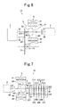
- a power transmission apparatus 12 according to present Embodying Mode No. 2 comprises an additional shaft 6 that is put in place parallelly to an input shaft 31 and output shaft 32 of a multistaged change-speed mechanism 3, and to an input shaft 21 of an internal combustion engine 2; and two transmission gears 62, 63 are put in place on the additional shaft 6.
- the additional shaft 6 is put in place on a side of a rotor 42 of a rotary electric device 4.
- One of the transmission gears 62, 63 namely, the transmission gear 63, meshes with a rotary-electric-device-side output gear 431 of a rotary-electric-device-side output shaft 43; and the other one of them, namely, the transmission gear 62, meshes with a final deceleration gear 71. Since it is possible to adjust the rotary direction of the output of the rotary electric device 4 by adding a shaft and interposing gears, it is possible to make it coincide with the rotary direction of the rotary power that is effected by way of the multistaged change-speed mechanism 3. And, by means of multiplying the number of gears on the additional shaft 6, the degree of freedom in gear ratio is increased more than that in the power transmission apparatus according Embodying Mode No. 2.
- Embodying Mode No. 4 according to the present invention will be explained in detail.
- Present Embodying Mode No. 4 comprises the same constructions as those of Embodying Mode No. 1 basically, and exhibits the same operations and advantageous effects as it does basically.
- it will be explained while focusing on distinct parts.
- a sun gear 81 of a planetary gear mechanism 8 is put in place coaxially with the shaft of a rotor 42 of a rotary electric device 4, an input shaft 31 of a multistaged change-speed mechanism 3 and an output shaft 21 of an internal combustion engine 2, as illustrated in Fig. 4 .
- the planetary gear mechanism 8 comprises the sun gear 81, which is connected to the rotor 42 of the rotary electric device 4 by way of a second power interrupting mechanism 52, a planetary gear 82, which is connected to a rotary-electric-device-side output shaft 43, and a ring gear 83, which is fixed so as to be unable to rotate.
- the planetary gear mechanism 8 on an inner peripheral side of the rotor 42.
- the degree of freedom in gear ratio is increased more in the present power transmission apparatus 13 than that in the power transmission apparatus 12 according to Embodying Mode No. 3 with the construction in which a shaft is added and the transmission gear is multiplied.
- the constructions of a first power interrupting mechanism 53 and second power interrupting mechanism 54 differ from those of the first power interrupting mechanism 51 and second power interrupting mechanism 52 according to Embodying Mode No. 1 through Embodying Mode No. 4.
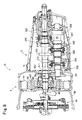
- Fig. 5 is an explanatory diagram in which the distinct parts are enlarged.
- an internal combustion engine 2 is positioned leftward to an input shaft 31. And, an opposite end of a counter shaft 33 (or an output shaft 32) is drawn under the input shaft 31.
- a rotor 42 of a rotary electric device 4 is supported rotatably to the input shaft 31 by a rotary supporting member 421 that is positioned on an outer peripheral side of the input shaft 31, and a stator 41 is positioned on an outer peripheral side of the rotor 42.
- the rotary electric device 4 comprises a sleeve 44 that engages with the rotor 42 not only integrally and rotatably but also movably in the axial direction.
- a spline which engages with an inner peripheral side of the rotor 42, is formed in an axial part on the outer peripheral side, and a groove 441 is formed in the remaining axial part on the outer peripheral side.
- the sleeve 44 is moved axially by way of a not-shown fork by means of driving an actuator because the fork engages with the groove 441.
- the rotary electric device 4 comprises a rotary sensor 45 for detecting a revolution speed of the rotary electric device 4 so as to make the revolution speed of the rotary electric device 4 controllable.
- a revolution speed of the rotary electric device 4 so as to make the revolution speed of the rotary electric device 4 controllable.
- it is installed between the rotary supporting member 421 and a case 90 that is positioned leftward in the drawing.
- the first power interrupting mechanism 53 engages with the input shaft 31 integrally and rotatably on an inner peripheral side of the rotor 42, because engager teeth 531 that engage with engager teeth 422 on the inner periphery of the sleeve 44 are formed on the outer periphery.
- the second power interrupting mechanism 54 is positioned on an inner peripheral side of the rotor 2, and engages integrally and rotatably with a rotary-electric-device-side output gear 431 that engages rotatably with the input shaft 31, because engager teeth 541 that engage with engager teeth 442 on the inner periphery of the sleeve 44 are formed on the outer periphery.
- the rotary-electric-device-side output gear 431 meshes always with an output gear 321, which engages with the output shaft 32 integrally and rotatably at an opposite end of the output shaft 32, because teeth are formed on the outer periphery of the rotary-electric-device-side output gear 431.
- the first power interrupting mechanism 53 is positioned more adjacently to a side of the internal combustion engine 2 in the axial direction than is the second power interrupting mechanism 54.
- the sleeve 44 moves toward one of the sides of the internal combustion engine 2, it engages with the first power interrupting mechanism 53; when it moves toward the other one of the sides, it engages with the second power interrupting mechanism 54; accordingly the interruptions are switched.
- the engager teeth 443 of the sleeve 44 have a length that is shorter than the axial distance between the engager teeth 531 of the first power interrupting mechanism 53 and the engager teeth 541 of the second interrupting mechanism 54.
- Embodying Mode No. 6 comprises the same constructions as those of the power transmission apparatuses 10-13 according to Embodying Mode No. 1 through Embodying Mode No. 4 and the power transmission apparatus according to Embodying Mode No. 5 basically, and exhibits the same operations and advantageous effects as they do basically.
- it will be explained while focusing on distinct parts.
- a clutch 55 that is ordinary (hereinafter, referred to as an ordinary clutch) is put in place between an output shaft 21 of an internal combustion engine 2 and a rotor 42 of a rotary electric device 42 (or an input shaft 31 of a multistaged change-speed mechanism 3, as illustrated in Fig. 6 .
- the power transmission apparatus 14 being shown in Fig. 6 is one in which the ordinary clutch 55 is added between the output shaft 21 and the rotor 42 in the power transmission apparatus 10 according to Embodying Mode No. 1. Since it can be likewise put in place in the power transmission apparatuses 11-13 according to Embodying Mode Nos. 2-4 as well, its diagrammatic representation is omitted.
- the ordinary clutch 55 switches the disconnection and connection between the output shaft 21 and the input shaft 31.
- the operations of this ordinary clutch 55 are controlled by means of a controlling unit through an actuator.
- the controlling unit keeps the state as it is; in a case where the internal combustion engine 2 is operating, it outputs a signal for stopping the internal combustion engine 2.
- the controlling unit keeps the state as it is; in a case where the ordinary clutch 55 is in the connected state, it outputs a signal for disconnecting the ordinary clutch 55.
- the controlling unit outputs a signal to the multistaged change-speed mechanism 3 to put it into the neutral state. And, it outputs a control signal to the first power interrupting mechanism 51 to put it into the disconnected state, and outputs a control signal to the second power interrupting mechanism 52 to put it into he connected state. And, it outputs a signal to the rotary-electric-device controller to drive the rotary electric device 4.
- the rotary power from the rotary electric device 4 is transmitted from the rotary-electric-device-side output shaft 43 to the rotary-electric-device-side output gear 431 and then to the output gear 321 in this order by way of the second power interrupting mechanism 52 that is in the connected state, and then the vehicle starts moving by means of the output from the rotary electric device 4 alone.
- the controlling unit outputs a signal to the multistaged change-speed mechanism 3 to select an appropriate gear-shift stage. And, it outputs a control signal to the first power interrupting mechanism 51 to put it into the connected state, and outputs a control signal to the second power interrupting mechanism 52 to put it into the disconnected state. Then, the controlling unit outputs a signal to the rotary-electric-device controller to drive the rotary electric device 4.
- the rotary power from the rotary electric device 4 is transmitted from the rotary-electric-device-side output shaft 43 to the input shaft 31 by way of the first power interrupting mechanism 51 that is in the connected state, is changed in speed with a speed-reducing ratio of the gear-shift stage in the multistaged change-speed mechanism 3, and is then output from the output shaft 32 of the multistaged change-speed mechanism 3. And, it is transmitted to the final gear 71 via the output gear 321 by means of the output of the output shaft 32, and then the vehicle starts moving by means of the output from the rotary electric device 4 alone.
- the controlling unit After detecting that the vehicle's speed has became a predetermined speed or more by means of the vehicle-speed signal, the controlling unit carries out the starting of the internal combustion engine 2 as follows.
- the controlling unit outputs a control signal to the ordinary clutch 55 to switch it to the connected state. And, after outputting such a signal that augments the output of the rotary electric device 4 to the rotary-electric-device controller until the internal combustion engine 2 starts, it outputs a signal, which switches the first power interrupting mechanism 51 to the connected state, to the actuator, and then outputs a signal to the internal combustion engine 2 to put it into the running state. And then, the internal combustion engine 2 is rotated by means of the rotor 42 via the first power interrupting mechanism 51, and accordingly the internal combustion engine 2 starts.
- the output from the rotary electric device 4 lowers temporarily by means of starting the internal combustion engine 2, it comes not to be detected by an operator or fellow passengers because it has been compensated by means of augmenting the output of the rotary electric device 4 during that period. After the starting of the internal combustion engine 2 is confirmed, it switches the first power interrupting mechanism 51 to the disconnected state.
- the controlling unit outputs a signal that puts the internal combustion engine 2 into the running state with a starter or alternator, and the like. And, the controlling unit outputs a signal, which switches the ordinary clutch 55 to the connected state, after the internal combustion engine 2 is started. It then switches the first power interrupting mechanism 51 to the disconnected state after connecting the ordinary clutch 55.
- the controlling unit outputs such a signal, which augments the output of the rotary electric device 4, to the rotary-electric-device controller until the internal combustion engine 2 starts. And, it outputs a signal, which puts the internal combustion engine 2 into the running state, and then outputs a signal, which switches the ordinary clutch 55 to the connected state. And then, the internal combustion engine 2 is rotated by means of the rotor 42 via the first power interrupting mechanism 51, and thereby the internal combustion engine 2 starts. Although the output from the rotary electric device 4 lowers temporarily by means of starting the internal combustion engine 2, it comes not to be detected by an operator or fellow passengers because it has been compensated by means of augmenting the output of the rotary electric device 4 during that period. After the starting of the internal combustion engine 2 is confirmed, it switches the first power interrupting mechanism 51 to the disconnected state.
- the controlling unit controls the revolution speed of the internal combustion engine 2 so as to make it coincide with a revolution speed of the input shaft 31 in one of the gear-shift stages in the multistaged change-speed mechanism 3 that coincides with the traveling speed of the vehicle (or a revolution speed of the output shaft 32 of the multistaged change-speed mechanism 3). And, it outputs a signal to the multistaged change-speed mechanism 3 to have it select one of the gear-shift stages.
- the controlling unit outputs a signal for turning the first power interrupting mechanism 51 into the disconnected state, and a signal for turning the second power interrupting mechanism 52 into the connected state, immediately before the ordinary clutch 55 is disconnected. Thereafter, it disconnects a current gear-shift stage, and thereby the vehicle is traveled with the output of the rotary electric device 4. And, the controlling unit outputs a signal so as to turn the second power interrupting mechanism 52 into the disconnected state before or after the multistaged change-speed mechanism 3 is connected to the next gear-shift stage and the ordinary clutch 55 is connected, and thereby the vehicle is traveled by means of the internal combustion engine 2.
- the ordinary clutch 55 When connecting the ordinary clutch 55, it controls the revolution speed of the internal combustion engine 2's output shaft 21 so as to be a proper revolution speed that is calculated from that of themultistagedchange-speedmechanism 3' s input shaft 31 and a gear-shift stage to be selected, and thereby the connection of the ordinary clutch 55 is carried out smoothly.
- the controlling unit outputs a signal for selecting a next gear-shift stage from the current gear-shift stage after disconnecting the ordinary clutch 55.
- the ordinary clutch 55 controls the revolution speed of the internal combustion engine 2's output shaft 21 so as to be a proper revolution speed that is calculated from that of themultistaged change-speedmechanism 3' s input shaft 31 and a gear-shift stage to be selected, and thereby the connection of the ordinary clutch 55 is carried out smoothly.
- the electric energy that has been stored in the electricity accumulator is a predetermined amount or less, it switches the first power interrupting mechanism 51 or the second power interrupting mechanism 52 to the connected state to rotate the rotor 42 of the rotary electric device 4, thereby carrying out electric power generation. It selects either one of the first power interrupting mechanism 51 and second power interrupting mechanism 52 to turn it into the connected state depending on which of them it turns into the connected state will result in higher electric-power-generation efficiency in the rotary electric device 4.
- a power transmission apparatus 15 according to present Embodying Mode No. 7 comprises the same constructions as those of the power transmission apparatuses 10-14 according to Embodying Mode No. 1 through Embodying Mode No. 5 basically, and exhibits the same operations and advantageous effects as they do basically. Hereinafter, it will be explained while focusing on distinct parts.
- the power transmission apparatus 15 As illustrated in Fig. 7 and Fig. 8 , the power transmission apparatus 15 according to present Embodying Mode No. 7 comprises an internal combustion engine 2, a multistaged change-speed mechanism 3, and a rotary electric device 4, a first power interrupting mechanism 53, a second power interrupting mechanism 54, an ordinary clutch 55, and a controlling unit (not shown in the drawings).
- the power transmission apparatus 15 according to the present embodying mode is an apparatus for automobile (not shown) in which the internal combustion engine is mounted in the front and the rear wheels are driven.
- the internal combustion engine is positioned on a side of the multistaged change-speed mechanism 3's input shaft 31 (or on the upstream side), and comprises an output shaft 21 that is connected to the input shaft 30 coaxially and is connected to a rotor 42 of the later-described rotary electric device 4 by way of the first power interrupting mechanism 53.
- the internal combustion engine 2 has a fuel supplying device, a throttle for controlling the amount of air supply, and the like; and these are controlled based on control signals from the outside so that their fuel-supply and air-supply amounts are controlled.
- the internal combustion engine 2 has a revolution-speed sensor (not shown) that detects a revolution speed of the output shaft 21 and then outputs a revolution-speed signal.
- the multistaged change-speed mechanism 3 comprises the input shaft 31, an output shaft 32, and a counter shaft 33; and is a gear-system multistaged change-speed mechanism that is constituted of a plurality of gear-shift stages which can change a rotary power that is input from the input shaft 31 in speed with a plurality of switchable speed reducing ratios, and which can then output it from the output shaft 32.
- the input shaft 31 is coupled to an output shaft 21 of the internal combustion engine 2 by way of the ordinary clutch 55.
- the change-speed mechanism it is possible to name those comprising gear-shift stages for 5 speeds or 6 speeds in the forward direction, and one-staged gear-shift stage in the reverse direction.
- the multistaged change-speed mechanism 3 is a mechanism that carries out the selection of the gear-shift stages by means of the combinations of selecting operations and shifting operations; and has actuators (not shown) that carry out the selecting operations and the shifting operations, respectively.
- the actuators carry out the selections of the gear-shift stages by carrying out the respective operations based on control signals from the outside.
- the construction of the present multistaged change-speed mechanism 3 is similar to the construction of automatic MT.
- the multistaged change-speed mechanism 3 has revolution-speed sensors (not shown) that detect the revolution speeds of the input and output shafts 32 and 32, and that then output them as revolution-speed signals.
- the output shaft 32 is put in place coaxially with the input shaft 31, the output shaft 21 of the internal combustion engine 2, and a rotary-electric-device-side output shaft 43 of the rotary electric device 4.
- the output shaft 32 is disposed to protrude from a side, which is opposite to an opposite end side where the input shaft 31 is coupled to the output shaft 21 of the internal combustion engine 2 in the axial direction, toward the outside of the multistaged change-speed mechanism 3.
- an output gear 322 which meshes with a driven gear 332 of the later-described counter shaft 33, is put in place integrally and rotatably at one of the opposite ends on a side of the input shaft 31.
- a gear (not shown in the drawings) of a differential mechanism (not shown in the drawings), which is to be joined to both driving wheels (not shown in the drawings) of vehicle, is joined to the other one of the opposite end sides of the output shaft 32.
- the counter shaft 33 is put in place parallelly to the input shaft 31 in the axial direction; and comprises a rotary-electric-device-side input gear 331 being disposed at one of the opposite ends on a side of the internal combustion engine 2, the driven gear 332 being disposed at the other one of the opposite end sides, and a plurality of counter gears 333-337 being disposed between the rotary-electric-device-side input gear 331 and the driven gear 322.
- the rotary-electric-device-side input gear 331 is capable of rotating integrally with the counter shaft 33, and meshes always with a rotary-electric-device-side output gear of the rotary electric device 4.
- the driven gear 322 is capable of rotating integrally with the counter shaft 33, and meshes always with the output gear 322 of the output shaft 32.
- the counter gears 333-337 mesh always with drive gears 311-314 that are disposed on the input shaft 31 integrally and rotatably, and with a drive gear 315 that is disposed on the input shaft 31 integrally and rotatably.
- the meshing counter gears and drive gears correspond to the respective gear-shift stages of vehicle.
- the rotary electric device 4 comprises a stator 41 that is positioned on the outer peripheral side and does not rotate, and the ring-shaped rotor 42 that is positioned on the inner peripheral side of the stator 41 and rotates.
- the rotor 42 is supported rotatably to the input shaft 31 by a rotary supporting member 421 that is positioned on the outer peripheral side of the input shaft 31 of the multistaged change-speed mechanism 3, and its rotary shaft is coaxial with the output shaft 21 of the internal combustion engine 2, and with the input shaft 31 of the multistaged change-speed mechanism 3.
- a rotary-electric-device-side output gear 431 which meshes with the rotary-electric-device-side input gear 331 of the counter shaft 33 is supported rotatably to and removably from the input shaft 31 on the outer peripheral side of the input shaft 31 in order to transmit the output of the rotary electric device 4 to the side of the output shaft 32, and is molded integrally with a rotary-electric-device-side output shaft 43.
- the rotary electric device 4 comprises a sleeve 44 that is capable of rotating integrally with the rotor 42 and engages with it movably in the axial direction.
- a spline is formed, spline whose outer-peripheral-side axial part engages with the inner peripheral side of the rotor 42, and a groove 441 is formed on the outer-peripheral-side axial remaining part.
- a not-shown fork engages with the groove 441, and then the sleeve 44 moves in the axial direction via the fork by means of driving an actuator.
- the rotary electric device 4 comprises a rotary sensor 45 that detect a revolution speed of the rotary electric device 4 to output it as a revolution-speed signal.
- revolution-speed sensors that detect the revolution speeds of the internal combustion engine 2's output shaft 21 and the revolution speeds of the multistaged change-speed mechanism 3' s input and output shafts 31, 32, or instead of them, the revolution speed of the output shaft 21, and the revolution speeds of the input and output shafts 31, 32 are controlled by controlling the revolution speed of the rotary electric device 4.
- the rotary electricity device 4 is used as an electricity generator as well as an electric motor, and is controlled by means of a rotary-electric-device controller (not shown in the drawings).
- an electric accumulator (not shown in the drawings) is an electric power source for the rotary electric device 4. The electricity that has been generated electrically by means of the rotary electric device 4 is accumulated electrically in the electric accumulator, and its control is carried out by means of the rotary-electric-device controller.
- engager teeth 531 On the outer periphery of the first power interrupting mechanism 53, engager teeth 531 are formed, engager teeth 531 which engage with the sleeve 44's inner-peripheral engager teeth 442 and engage with the input shaft 31 integrally and rotatably on the inner peripheral side of the rotor 42.
- engager teeth 541 On the outer periphery of the second power interrupting mechanism 54, engager teeth 541 are formed, engager teeth 541 which engage with the rotary-electric-deice-side output gear 431 integrally and rotatably, rotary-electric-deice-side output gear 431 which is positioned on the inner peripheral side of the rotor 2 and which engages with the input shaft 31 rotatably.
- the rotary-electric-device-side output gear 431 meshes always with a rotary-electric-device-side input gear 331 that engages with the output shaft 32 integrally and rotatably at one of the opposite ends of the output shaft 32.
- the first power interrupting mechanism 53 is positioned more adjacently to one of the sides of the internal combustion engine 2 in the axial direction than is the second power interrupting mechanism 54.
- the sleeve 44 engages with the first power interrupting mechanism 53 when it moves toward one of the sides of the internal combustion engine 2; it engages with the second power interrupting mechanism 54 when it moves toward the other one of the sides; and thereby the interruptions are switched.
- the controlling unit carries out the control for the start and stop of the internal combustion engine 2, the control for the driving of the rotary electric device 4 and the regeneration, and the control for the interruption of both power interrupting mechanisms.
- the controlling unit can be materialized by adding a logic that carries out controls as set forth below to ECU, which has been usually onboard in vehicle, or to ECU, which is to be disposed in vehicle newly, or the like.
- the controlling unit is a device to which the following are input: the revolution-speed signals that are output respectively from the internal combustion engine 2 and multistaged change-speed mechanism 3; vehicle-speed signals that specify speeds of the vehicle in which the present apparatus is onboard; and operational signals that specify the operated magnitudes of the accelerator and brakes for operating vehicle; and it is a device which outputs control signals to the internal combustion engine 2, to the multistaged change-speed mechanism 3, and to the first and second power interrupting mechanisms 53, 54.
- Basic operations of the power transmission apparatus 15 according to present Embodying Mode No. 7 are the same as the operations of the power transmission apparatus 14 according to Embodying Mode No. 5, and exhibits advantageous effects that are similar to the advantageous effects of that.
- basic operations and advantageous effects where the ordinary clutch 55 according to the present power transmission apparatus 15 is removed are similar to the operations and advantageous effects of the power transmission apparatuses 10-13 according to Embodying Mode Nos. 1-4.
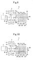
- a power transmission apparatus 16 according present Embodying Mode No. 8 comprises the same constructions as those of the power transmission apparatus 15 according to Embodying Mode No. 7 basically, and exhibits the same operations and advantageous effects as it does basically. Hereinafter, it will be explained while focusing on distinct parts.
- the power transmission apparatus 16 is an apparatus for automobile (not shown) in which the internal combustion engine is mounted in the front and the rear wheels are driven; an input shaft 31 of a multistaged change-speed mechanism 3 is reduced, and an output shaft 32 thereof is extended, as illustrated in Fig. 9 .
- Drive gears 311-315 which mesh always with counter gears 333-337 of a counter shaft, are supported rotatably to the output shaft 32. And, it comprises an additional shaft 6 that is put in place parallelly to the input shaft 31, output shaft 32 and counter shaft 33.
- the input shaft 31 comprises an input gear 316 at an opposite end on the side of the output shaft 32 in the axial direction.
- the input gear 31 meshes always with a counter-shaft-side input gear 338 of the counter shaft that is put in place parallelly to the input shaft 31.
- the drive gears 311-314 which mesh always with the counter gears 333-337 of the counter shaft 33, are supportedrotatably.
- An additional-shaft-side input gear 323, which meshes with a transmission gear 65 of a later-described additional shaft 6 is supported rotatably to the output shaft 32 and integrably with the output shaft 32.
- the additional shaft 6 comprises a transmission gear 64 at one of the opposite ends, transmission gear 64 which meshes always with a rotary-electric-device-side output gear 431 of a rotary electric device 4 at one of the opposite ends on the side of the internal combustion engine 2, and a transmission gear 65 at the other one of the opposite ends, transmission gear 65 which meshes always with the additional-shaft-side input gear 323 that is supported rotatably to the output shaft 32.
- the present power transmission apparatus 16 according to present Embodying Mode No. 8 is a so-called input reduction type change-speed machine. It becomes feasible to connect the rotary electric device 4 to either one of the side of the input shaft 31 of the multistaged change-speed mechanism 3 and the side of the output shaft 32 by adding one extra shaft and some gears to an existing change-speed machine with such a construction.
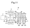
- a power transmission apparatus 17 according present Embodying Mode No. 9 comprises the same constructions as those of the power transmission apparatus 16 according to Embodying Mode No . 8 basically, and exhibits the same operations and advantageous effects as it does basically. Hereinafter, it will be explained while focusing on distinct parts.
- the power transmission apparatus 17 according to present Embodying Mode No. 9 is an automobile in which an internal combustion engine 2 is onboard in the vehicular front and the rear wheels are driven in the same manner as the power transmission apparatus 16 according to Embodying Mode No. 8, and in which an input reduction type change-speed machine is employed.
- a cylindrical shaft is used for a counter shaft 33, and an additional shaft 6 is penetrated through the inside of the counter shaft 33. Since it is possible to add the additional shaft 6 by thus adapting the counter shaft 33 into a cylindrical shape, the expansion in the shaft's diametric direction is suppressed, compared with the power transmission apparatus 16 according to Embodying Mode No. 8.
- a power transmission apparatus 18 according present Embodying Mode No. 10 comprises the same constructions as those of the power transmission apparatus 16 according to Embodying Mode No. 8 basically, and exhibits the same operations and advantageous effects as it does basically. Hereinafter, it will be explained while focusing on distinct parts.
- the power transmission apparatus 18 according to present Embodying Mode No. 10 is an automobile in which an internal combustion engine 2 is onboard in the vehicular front and the rear wheels are driven in the same manner as the power transmission apparatus 16 according to Embodying Mode No. 8, and in which an input reduction type change-speed machine is employed.
- an additional-shaft-side input gear 323 is put in place between two of an output shaft 32's drive gears 311-316 in the axial direction.
- themultistaged change-speed mechanism 3 it is possible to use, not AMT, but ordinary MT that is free from any actuator. If such is the case, it is desirable that both of the following can be detected when switching the gear-shift stages: not only the switching of the gear-shift stages is carried out but also which of the gear-shift stages is selected next. It is possible to make the gear-shifting operations progress smoothly by means of the information on the progress of speed change and on the next gear-shift stage.
- the detection that a subsequent stage has been obtained can be obtained by detecting that the shift lever is shifted from a gate at the neutral position into a subsequent gear-shift stage and has then been passed through a gate at that shift stage.
Landscapes
- Engineering & Computer Science (AREA)
- Mechanical Engineering (AREA)
- Chemical & Material Sciences (AREA)
- Combustion & Propulsion (AREA)
- Transportation (AREA)
- General Engineering & Computer Science (AREA)
- Arrangement Of Transmissions (AREA)
- Electric Propulsion And Braking For Vehicles (AREA)
- Hybrid Electric Vehicles (AREA)
- Connection Of Motors, Electrical Generators, Mechanical Devices, And The Like (AREA)
- Structure Of Transmissions (AREA)
- Transmission Devices (AREA)
- Friction Gearing (AREA)
Applications Claiming Priority (2)
| Application Number | Priority Date | Filing Date | Title |
|---|---|---|---|
| JP2007271556 | 2007-10-18 | ||
| PCT/JP2008/068678 WO2009051143A1 (ja) | 2007-10-18 | 2008-10-15 | 動力伝達装置 |
Publications (2)
| Publication Number | Publication Date |
|---|---|
| EP2199136A1 true EP2199136A1 (de) | 2010-06-23 |
| EP2199136A4 EP2199136A4 (de) | 2011-12-28 |
Family
ID=40567405
Family Applications (1)
| Application Number | Title | Priority Date | Filing Date |
|---|---|---|---|
| EP08839641A Withdrawn EP2199136A4 (de) | 2007-10-18 | 2008-10-15 | Energieübertragungsvorrichtung |
Country Status (4)
| Country | Link |
|---|---|
| US (1) | US20100180722A1 (de) |
| EP (1) | EP2199136A4 (de) |
| JP (2) | JPWO2009051143A1 (de) |
| WO (1) | WO2009051143A1 (de) |
Cited By (6)
| Publication number | Priority date | Publication date | Assignee | Title |
|---|---|---|---|---|
| EP2216567A3 (de) * | 2009-02-04 | 2011-11-30 | AISIN AI Co., Ltd. | Steuerungsverfahren für elektrische Rotationsmaschine beim Hybridgetriebe |
| EP2540590A4 (de) * | 2010-02-23 | 2013-10-16 | Aisin Ai Co Ltd | Kraftübertragungsvorrichtung für ein hybridfahrzeug mit vierradantrieb |
| EP2684755A4 (de) * | 2011-03-11 | 2014-08-13 | Aisin Ai Co Ltd | Handschaltung |
| DE202016102495U1 (de) | 2016-05-09 | 2017-08-11 | Hofer-Pdc Gmbh | Klauenschaltelement, insbesondere für einen Hybridantriebsstrang mit leistungsverzweigendem Getriebe |
| WO2018161990A1 (de) * | 2017-03-06 | 2018-09-13 | Schaeffler Technologies AG & Co. KG | Hybridmodul mit integrierter sensoreinrichtung sowie hybridantriebsstrang mit hybridmodul |
| US10843547B2 (en) * | 2016-04-14 | 2020-11-24 | Schaeffler Technologies AG & Co. KG | Drive train for a hybrid motor vehicle |
Families Citing this family (27)
| Publication number | Priority date | Publication date | Assignee | Title |
|---|---|---|---|---|
| EP2307764B1 (de) * | 2008-07-03 | 2013-09-25 | Deere & Company | Getriebe mit kriechganganordnung |
| JP5307587B2 (ja) * | 2009-03-11 | 2013-10-02 | アイシン・エーアイ株式会社 | 車両の動力伝達制御装置 |
| JP5307588B2 (ja) * | 2009-03-11 | 2013-10-02 | アイシン・エーアイ株式会社 | 車両の動力伝達制御装置 |
| JP2010246307A (ja) * | 2009-04-08 | 2010-10-28 | Aisin Ai Co Ltd | 車両の動力伝達制御装置 |
| JP2011105158A (ja) * | 2009-11-18 | 2011-06-02 | Aisin Ai Co Ltd | ハイブリッド車の動力伝達機構 |
| JP5400953B2 (ja) * | 2010-03-31 | 2014-01-29 | 本田技研工業株式会社 | ハイブリッド式パワーユニット |
| US8657712B2 (en) | 2010-09-15 | 2014-02-25 | Chrysler Group Llc | Multi-speed drive unit |
| US8444516B2 (en) | 2010-09-15 | 2013-05-21 | Chrysler Group Llc | Multi-speed drive unit |
| JP5812592B2 (ja) * | 2010-10-26 | 2015-11-17 | 日野自動車株式会社 | ハイブリッド車両の動力伝達装置のレゾルバの取り付け構造 |
| JP5489954B2 (ja) * | 2010-10-27 | 2014-05-14 | 本田技研工業株式会社 | 車両用駆動装置 |
| CN102303508B (zh) * | 2011-06-30 | 2014-02-12 | 重庆青山工业有限责任公司 | 换档时动力不中断的amt电动车传动系统 |
| JP5831253B2 (ja) * | 2012-01-26 | 2015-12-09 | トヨタ自動車株式会社 | ハイブリッド車両の制御装置 |
| FR2988675B1 (fr) * | 2012-04-03 | 2014-03-14 | Renault Sa | Procede de commande de la recharge de la batterie sur un vehicule hybride |
| DE102012214457A1 (de) | 2012-08-14 | 2014-02-20 | Zf Friedrichshafen Ag | Antriebssystem für ein Fahrzeug |
| KR101428220B1 (ko) | 2012-11-23 | 2014-08-07 | 현대자동차주식회사 | 자동화 수동변속기 |
| JP6095387B2 (ja) * | 2013-01-31 | 2017-03-15 | アイシン精機株式会社 | ハイブリッド車両用駆動装置 |
| DE102014102343B4 (de) | 2014-02-24 | 2025-03-27 | Dr. Ing. H.C. F. Porsche Aktiengesellschaft | Antriebsstrang für ein Hybridkraftfahrzeug |
| JP6239451B2 (ja) * | 2014-06-30 | 2017-11-29 | アイシン・エーアイ株式会社 | 車両の動力伝達制御装置 |
| JP6270653B2 (ja) * | 2014-07-25 | 2018-01-31 | トヨタ自動車株式会社 | 車両用駆動装置 |
| JP6494949B2 (ja) * | 2014-08-19 | 2019-04-03 | 日野自動車株式会社 | ハイブリッド車両の動力伝達装置 |
| KR101573633B1 (ko) * | 2014-09-30 | 2015-12-01 | 현대자동차주식회사 | 하이브리드의 변속기 구조 및 모드 변환 방법 |
| JP6491051B2 (ja) * | 2015-06-11 | 2019-03-27 | アイシン・エーアイ株式会社 | 車両の動力伝達制御装置 |
| DE102016207103B4 (de) * | 2016-04-27 | 2018-06-07 | Schaeffler Technologies AG & Co. KG | Getriebe mit Kupplung und unterbrechungsfrei schaltbarer Schalteinheit zum Schalten zwischen den Getriebeeingangswellen |
| US11531089B2 (en) | 2018-09-06 | 2022-12-20 | Blickfeld GmbH | Coaxial setup for light detection and ranging, lidar, measurements |
| US11712955B1 (en) | 2022-08-18 | 2023-08-01 | Dana Belgium N.V. | Multi-speed electric axle and electric axle shifting strategy |
| US12337679B2 (en) | 2023-03-16 | 2025-06-24 | Dana Belgium N.V. | Electric drive unit and method for drive unit operation |
| US12214894B1 (en) * | 2024-05-17 | 2025-02-04 | Archer Aviation Inc. | Motor gearbox assembly with layshaft for EVTOL aircraft |
Family Cites Families (9)
| Publication number | Priority date | Publication date | Assignee | Title |
|---|---|---|---|---|
| JPH10291421A (ja) * | 1997-04-18 | 1998-11-04 | Nissan Motor Co Ltd | ハイブリッドパワートレイン |
| DE19960621B4 (de) * | 1999-12-16 | 2006-12-21 | Daimlerchrysler Ag | Hybridantrieb für Fahrzeuge |
| JP3556893B2 (ja) * | 2000-10-11 | 2004-08-25 | 本田技研工業株式会社 | 動力伝達機構 |
| DE10052231A1 (de) * | 2000-10-21 | 2002-05-02 | Daimler Chrysler Ag | Fahrzeug |
| JP3675341B2 (ja) * | 2001-02-21 | 2005-07-27 | 日産自動車株式会社 | 車両用駆動装置 |
| US7108626B2 (en) * | 2001-09-26 | 2006-09-19 | Luk Lamellen Und Kupplungsbau Beteiligungs Kg | Drive assembly |
| JP3499852B2 (ja) * | 2001-12-03 | 2004-02-23 | 本田技研工業株式会社 | 動力伝達機構 |
| JP2004161053A (ja) * | 2002-11-11 | 2004-06-10 | Nissan Motor Co Ltd | ハイブリッド車両の駆動装置 |
| JP4226610B2 (ja) * | 2006-03-28 | 2009-02-18 | 本田技研工業株式会社 | ハイブリッド車両 |
-
2008
- 2008-10-15 JP JP2009538114A patent/JPWO2009051143A1/ja active Pending
- 2008-10-15 WO PCT/JP2008/068678 patent/WO2009051143A1/ja not_active Ceased
- 2008-10-15 US US12/602,038 patent/US20100180722A1/en not_active Abandoned
- 2008-10-15 EP EP08839641A patent/EP2199136A4/de not_active Withdrawn
-
2011
- 2011-08-10 JP JP2011174869A patent/JP5138803B2/ja not_active Expired - Fee Related
Cited By (9)
| Publication number | Priority date | Publication date | Assignee | Title |
|---|---|---|---|---|
| EP2216567A3 (de) * | 2009-02-04 | 2011-11-30 | AISIN AI Co., Ltd. | Steuerungsverfahren für elektrische Rotationsmaschine beim Hybridgetriebe |
| EP2540590A4 (de) * | 2010-02-23 | 2013-10-16 | Aisin Ai Co Ltd | Kraftübertragungsvorrichtung für ein hybridfahrzeug mit vierradantrieb |
| EP2684755A4 (de) * | 2011-03-11 | 2014-08-13 | Aisin Ai Co Ltd | Handschaltung |
| US10843547B2 (en) * | 2016-04-14 | 2020-11-24 | Schaeffler Technologies AG & Co. KG | Drive train for a hybrid motor vehicle |
| DE202016102495U1 (de) | 2016-05-09 | 2017-08-11 | Hofer-Pdc Gmbh | Klauenschaltelement, insbesondere für einen Hybridantriebsstrang mit leistungsverzweigendem Getriebe |
| DE202016103022U1 (de) | 2016-05-09 | 2017-08-31 | Hofer-Pdc Gmbh | Klauenschaltelement, insbesondere für einen Hybridantriebsstrang mit leistungsverzweigendem Getriebe |
| DE102016108552B4 (de) | 2016-05-09 | 2023-09-14 | Hofer Powertrain Innovation Gmbh | Hybridantriebsstrang mit leistungsverzweigendem Getriebe, einer koaxial zwei Wellen umfassenden Zentralwelle und einem mehrere Schaltstellungen aufweisenden Kraftflussverbinder sowie dazugehöriges Schaltverfahren, das unter Last ausführbar ist |
| WO2018161990A1 (de) * | 2017-03-06 | 2018-09-13 | Schaeffler Technologies AG & Co. KG | Hybridmodul mit integrierter sensoreinrichtung sowie hybridantriebsstrang mit hybridmodul |
| US11225132B2 (en) | 2017-03-06 | 2022-01-18 | Schaeffler Technologies AG & Co. KG | Hybrid module with integrated sensor device, and hybrid powertrain comprising a hybrid module |
Also Published As
| Publication number | Publication date |
|---|---|
| US20100180722A1 (en) | 2010-07-22 |
| JP2012017099A (ja) | 2012-01-26 |
| JP5138803B2 (ja) | 2013-02-06 |
| WO2009051143A1 (ja) | 2009-04-23 |
| JPWO2009051143A1 (ja) | 2011-03-03 |
| EP2199136A4 (de) | 2011-12-28 |
Similar Documents
| Publication | Publication Date | Title |
|---|---|---|
| EP2199136A1 (de) | Energieübertragungsvorrichtung | |
| JP6727141B2 (ja) | オフセットされた電気機械を有するハイブリッドトランスミッション、及びギアチェンジの制御方法 | |
| EP2161154B1 (de) | Kraftübertragungssystem für fahrzeug | |
| KR100653116B1 (ko) | 이중 클러치를 구비한 자동차용 변속기와 이 변속기의 작동 방법 | |
| JP5480248B2 (ja) | 動力伝達装置 | |
| EP3284977B1 (de) | Vorrichtung zur steuerung des starts eines elektrofahrzeugs | |
| CN101801752B (zh) | 混合动力驱动装置的控制装置 | |
| CN102939214A (zh) | 混合动力车辆用驱动装置 | |
| EP2759435A1 (de) | Fahrzeugeinparkvorrichtung und Verfahren zum Einparken eines Fahrzeugs | |
| JP2009107626A (ja) | ハイブリッド車両用動力伝達装置 | |
| KR102529391B1 (ko) | 차량용 변속장치 | |
| WO2011021517A1 (ja) | ハイブリッド車両のエンジン始動制御装置 | |
| JP2017072181A (ja) | デュアルクラッチ式変速機 | |
| JP2011126318A (ja) | ハイブリッド電気自動車の発進制御装置 | |
| US20100234172A1 (en) | Vehicular power transmission control apparatus | |
| CN107813811B (zh) | 混合动力车辆的控制装置 | |
| JP2013169831A (ja) | ハイブリット車両 | |
| CN101223046A (zh) | 混合动力变速器 | |
| JP4292732B2 (ja) | ハイブリッド車両用動力伝達装置 | |
| CN103010205A (zh) | 车辆的动力传递控制装置 | |
| RU2486085C2 (ru) | Система управления трансмиссией в транспортных средствах | |
| JP2010247689A (ja) | 車両の動力伝達制御装置 | |
| JP2012056510A (ja) | ハイブリッド車両の駆動装置 | |
| CN112533784A (zh) | 有两个等效行驶方向的车辆的驱动机构和操作该种车辆的方法 | |
| JP2013508221A (ja) | 車両用ドライブトレイン |
Legal Events
| Date | Code | Title | Description |
|---|---|---|---|
| PUAI | Public reference made under article 153(3) epc to a published international application that has entered the european phase |
Free format text: ORIGINAL CODE: 0009012 |
|
| 17P | Request for examination filed |
Effective date: 20091130 |
|
| AK | Designated contracting states |
Kind code of ref document: A1 Designated state(s): AT BE BG CH CY CZ DE DK EE ES FI FR GB GR HR HU IE IS IT LI LT LU LV MC MT NL NO PL PT RO SE SI SK TR |
|
| AX | Request for extension of the european patent |
Extension state: AL BA MK RS |
|
| DAX | Request for extension of the european patent (deleted) | ||
| A4 | Supplementary search report drawn up and despatched |
Effective date: 20111128 |
|
| RIC1 | Information provided on ipc code assigned before grant |
Ipc: B60L 11/14 20060101ALI20111122BHEP Ipc: B60K 6/547 20071001ALI20111122BHEP Ipc: B60K 6/48 20071001ALI20111122BHEP Ipc: B60K 6/40 20071001ALI20111122BHEP Ipc: B60K 6/387 20071001ALI20111122BHEP Ipc: B60K 6/365 20071001ALI20111122BHEP Ipc: B60K 6/26 20071001ALI20111122BHEP Ipc: B60K 6/36 20071001AFI20111122BHEP |
|
| STAA | Information on the status of an ep patent application or granted ep patent |
Free format text: STATUS: THE APPLICATION HAS BEEN WITHDRAWN |
|
| 18W | Application withdrawn |
Effective date: 20120515 |