EP2194635A1 - Linearer schwingungserreger - Google Patents
Linearer schwingungserreger Download PDFInfo
- Publication number
- EP2194635A1 EP2194635A1 EP08834069A EP08834069A EP2194635A1 EP 2194635 A1 EP2194635 A1 EP 2194635A1 EP 08834069 A EP08834069 A EP 08834069A EP 08834069 A EP08834069 A EP 08834069A EP 2194635 A1 EP2194635 A1 EP 2194635A1
- Authority
- EP
- European Patent Office
- Prior art keywords
- linear actuator
- vibrating linear
- center
- output portions
- electromagnetic core
- Prior art date
- Legal status (The legal status is an assumption and is not a legal conclusion. Google has not performed a legal analysis and makes no representation as to the accuracy of the status listed.)
- Withdrawn
Links
Images


Classifications
-
- H—ELECTRICITY
- H02—GENERATION; CONVERSION OR DISTRIBUTION OF ELECTRIC POWER
- H02K—DYNAMO-ELECTRIC MACHINES
- H02K33/00—Motors with reciprocating, oscillating or vibrating magnet, armature or coil system
- H02K33/02—Motors with reciprocating, oscillating or vibrating magnet, armature or coil system with armatures moved one way by energisation of a single coil system and returned by mechanical force, e.g. by springs
- H02K33/04—Motors with reciprocating, oscillating or vibrating magnet, armature or coil system with armatures moved one way by energisation of a single coil system and returned by mechanical force, e.g. by springs wherein the frequency of operation is determined by the frequency of uninterrupted AC energisation
- H02K33/06—Motors with reciprocating, oscillating or vibrating magnet, armature or coil system with armatures moved one way by energisation of a single coil system and returned by mechanical force, e.g. by springs wherein the frequency of operation is determined by the frequency of uninterrupted AC energisation with polarised armatures
-
- B—PERFORMING OPERATIONS; TRANSPORTING
- B26—HAND CUTTING TOOLS; CUTTING; SEVERING
- B26B—HAND-HELD CUTTING TOOLS NOT OTHERWISE PROVIDED FOR
- B26B19/00—Clippers or shavers operating with a plurality of cutting edges, e.g. hair clippers, dry shavers
- B26B19/28—Drive layout for hair clippers or dry shavers, e.g. providing for electromotive drive
- B26B19/282—Motors without a rotating central drive shaft, e.g. linear motors
-
- B—PERFORMING OPERATIONS; TRANSPORTING
- B26—HAND CUTTING TOOLS; CUTTING; SEVERING
- B26B—HAND-HELD CUTTING TOOLS NOT OTHERWISE PROVIDED FOR
- B26B19/00—Clippers or shavers operating with a plurality of cutting edges, e.g. hair clippers, dry shavers
- B26B19/28—Drive layout for hair clippers or dry shavers, e.g. providing for electromotive drive
- B26B19/288—Balance by opposing oscillation
Definitions
- the present invention relates to a vibrating linear actuator used as a drive source of a device such as a reciprocating electric shaver.
- Patent Literature 1 a conventional vibrating linear actuator is know, which includes: an electromagnetic core block (a fixed element block) having an electric magnet; and magnetic blocks (movable elements) each having a permanent magnet and a back-yoke.
- the electromagnetic core block and the magnetic blocks are placed so that the electric magnet is opposed to each permanent magnet with a small gap therebetween.
- the electric magnet is supplied with current to reciprocatingly drive the magnetic blocks relative to the electromagnetic core block.
- the two magnetic blocks are arranged adjacent to each other and are reciprocatingly driven in opposite phase.
- Patent Literature 1 Japanese Patent Laid-open Publication No. 2005-354879
- the drive element provided for each of the two magnetic blocks arranged adjacent to each other is provided with the single output portion.
- the two output portions provided for the magnetic blocks are therefore oppositely placed on each side of a center-of-gravity line which passes through a center-of-gravity of the vibrating linear actuator or a device incorporating the vibrating linear actuator and extends in a direction that the electromagnetic core block and each magnetic block are arranged.
- an object of the present invention is to provide a vibrating linear actuator with vibration suppressed.
- An invention of claim 1 achieving the aforementioned object is a vibrating linear actuator including: an electromagnetic core block including an electric magnet; and a magnetic block including a permanent magnet and a back-yoke, the permanent magnet being opposed to the electric magnet with space therebetween, and the vibrating linear actuator in which one or both of the electromagnetic core block and the magnetic block being reciprocatingly driven by supplying current to the electric magnet, in which one of the electromagnetic core block and the magnetic block which is reciprocatingly driven is configured to serve as movable elements, the movable elements are arranged adjacent to each other and reciprocatingly driven in opposite phase, at least one of drive elements provided for the movable elements is provided with a plurality of output portions, and the plurality of output portions are placed on each side of a center-of-gravity line which passes through a center-of-gravity of the vibrating linear actuator or a device incorporating the vibrating linear actuator and extends in a direction that the electromagnetic core block and each magnetic block are arranged.
- An invention according to claim 2 is the vibrating linear actuator according to claim 1 in which a coupling portion holding substantially a constant gap between the electric magnet and the permanent magnet is provided between the electromagnetic core block and the magnetic block.
- An invention according to claim 3 is the vibrating linear actuator according to claim 1 or 2 in which at least one of the drive elements other than the drive elements provided with the plurality of output portions is provided with a single output portion and the single output portion is placed on the center-of-gravity line.
- An invention according to claim 4 is the vibrating linear actuator according to any one of claims 1 to 3 in which the plurality of output portions are placed substantially symmetrically with respect to the center-of-gravity line.
- the vibrating linear actuator includes the plurality of movable elements at which are reciprocatingly driven in opposite phase, and at least one of the drive elements provided for the movable elements is provided with the plurality of output portions.
- the plurality of output portions are arranged on each side of the center-of-gravity line of the center-of-gravity of the vibrating linear actuator or the device incorporating the vibrating linear actuator. Accordingly, when the plurality of output portions move in a same direction, the rotational moments generated at the output portions act in the directions opposite to each other.
- the rotational moment generated at the output portions placed on one side of the center-of-gravity acts so as to cancel the rotational moment on the other side. It is therefore possible to reduce the rotational movement of the vibrating linear actuator around the center-of gravity, thus reducing the vibration of the vibrating linear actuator.
- the coupling portion is provided between the electromagnetic core block and magnetic block to hold substantially constant space between the electromagnetic core block and magnetic block. It is therefore possible to stabilize the drive of the vibrating linear actuator, thus enhancing the effect on suppressing the vibration of the vibrating linear actuator.
- At least one of the drive elements other than the drive elements provided with the plurality of movable elements is provided with the single output portion, and the single output portion is placed on the center-of-gravity line. This can prevent generation of the rotational moment at the above output portion. The effect of suppressing the vibration of the vibrating linear actuator can be therefore further enhanced.
- the plurality of output portions are placed substantially symmetrically with respect to the center-of-gravity line.
- rotational moments having same magnitude but pointing in opposite directions are generated. Accordingly, the generated rotational moments are canceled each other, thus further enhancing the effect of suppressing the vibration of the vibrating linear actuator.
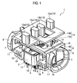
- a vibrating linear actuator 1 of a first embodiment includes: an electromagnetic core block 3 having an electric magnet 2; and magnetic blocks 6 each having a permanent magnet 4 and a back-yoke 5.
- the magnetic blocks 6 are configured to be reciprocatingly driven relative to the electromagnetic core block 3 by supplying current to the electric magnet 2.
- the reciprocatingly driven magnetic blocks 6 are configured to serve as movable elements.
- the magnetic blocks 6 as the movable elements are composed of first and second magnetic blocks 6a and 6b which are independent from each other.
- the first and second magnetic blocks 6a and 6b are arranged adjacent to each other in a direction perpendicular to the vibrating direction of the magnetic blocks 6 (in a C direction).
- coupling portions 7 and coupling spring portions 8 are provided between the electromagnetic core block 3 and magnetic blocks 6.
- the coupling portions 7 connect the electromagnetic core block 3 and the magnetic blocks 6 with space provided therebetween.
- the coupling spring portions 8 set a specific natural frequency of the magnetic blocks 6.
- the electromagnetic core block 3 includes the electric magnet 2 which is formed by providing electric winding wire 11 through a bobbin 10 for a core 9 composed of layers of a sintered magnetic material or iron plates.
- a base 12 is fixed by screwing or press fitting.
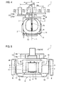
- each magnetic block 6 the permanent magnet 4 is provided in the surface thereof facing the magnetic surface of the electric magnet 2 (the lower surface in FIG. 2 ). At the back of the permanent magnet 4 (in the upper surface in FIG. 2 ), the back-yoke 5 is embedded. In the surface of the magnetic blocks 6 opposite to each permanent magnet 4 (in the upper surface in FIG. 2 ), drive elements 13 are later-attached by screws 14. The drive elements 13 are provided with output portions 15.
- not-shown inner blades are attached to the output portions 15 of the drive elements 13. Each inner blade slides on a porous outer blade provided for head part of the body of the electric shaver to cut beard drawn from the outside.
- the vibrating linear actuator 1 is thus used for driving the electric shaver.
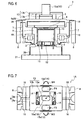
- the drive elements 13 include first and second drive elements 13a and 13b which are provided for the first and second magnetic blocks 6a and 6b, respectively.
- the first drive element 13a has a rectangular plate shape with long sides extending in the width direction of FIG. 4 (in the C direction).
- the second drive element 13b is placed above the upper surface of the first drive element 13a with a small gap therebetween and is shaped in a rectangular frame plate surrounding an end of the rectangular first drive element 13a.
- Each of the first and second drive elements 13a and 13b is provided with two of the output portions 15.
- the first and second output portions 15a and 15b are provided on the both longitudinal ends of the first drive element 13a, and the third and fourth output portions 15c and 15d are provided for the both side edges of the second drive element 13b in the width direction (in the C direction).
- upper connecting portions 16 are integrally formed so as to face in the outward direction, which is equal to the vibrating direction.
- an end (an upper end) of the corresponding coupling portion 7 is integrally formed.
- a lower connecting portion 17 is integrally formed.
- Each coupling portion 7 is shaped in a plate and is configured to have enough rigidity to hold the magnetic block 6 while allowing flexural deformation thereof in the vibrating direction.
- the first and second magnetic blocks 6a and 6b are arranged adjacent to each other in a direction which is orthogonal to the vibrating direction and the direction that pole faces of each permanent magnet 4 and electric magnet 2 are opposed to each other.
- the first and second magnetic blocks 6a and 6b arranged adjacent to each other are coupled to each other by coupling spring portions 8.
- Each of the coupling spring portions 8 is formed in a ring shape and springs in the vibrating direction of the first and second magnetic blocks 6a and 6b.
- An end of each coupling spring portion 8 is integrally joined to the upper connecting portion 16 of the first magnetic block 6a, and the other end is integrally joined to the upper connecting portion 16 of the second magnetic block 6b.
- the first and second magnetic blocks 6a and 6b are resonated by the coupling spring portions 8.
- the lower connecting portions 17 which are adjacent in the direction that the first and second magnetic blocks 6a and 6b are arranged (in the C direction) are integrally fixed to each other by an end joint portion 18. Accordingly, the first and second magnetic blocks 6a and 6b placed adjacent to each other are integrated by the coupling spring portions 8 at the both ends in the vibrating direction and are also integrated by the end joint portions 18 integrally connecting the lower connecting portions 17.
- the end joint portions 18 are attached to the base 12 of the electromagnetic core block 3.
- the magnetic blocks 6a and 6b are thus reciprocatingly driven relative to the electric core blocks 3.
- the magnetic blocks 6a and 6b are reciprocatingly driven in opposite phase.
- the output portions 15a and 15b of the first magnetic block 6a and the output portions 15c and 15d of the second magnetic block 6b are placed on each side of a center-of-gravity line L which passes through a center-of-gravity G of the vibrating linear actuator 1 (or an electric shaver as a device incorporating the vibrating linear actuator 1) and extends in the direction that the electromagnetic core block 3 and each magnetic block 6 are arranged (in the vertical direction in FIG. 4 ).
- the output portion 15a of the first drive element 13a is disposed at a distance D1 from the center-of-gravity line L on a side thereof in the width C direction (on the left side in FIG. 4 ) while the other output portion 15b of the first drive element 13a is disposed at a distance D2 (D1 # D2) from the center-of-gravity line L on the other side thereof in the width C direction (on the right side in FIG. 4 ).
- the output portion 15c of the second drive element 13b is disposed at a distance D3 from the center-of-gravity line L on a side thereof in the width C direction (on the left side in FIG.
- the drive elements 13a and 13b provided for the first and second magnetic blocks 6a and 6b, which are reciprocatingly driven in opposite phase each includes two output portions, which are 15a and 15b, and 15c and 15d.
- the paired output portions 15a and 15b are placed on each side of the center-of-gravity line L, and the paired output portions 15c and 15d are placed on each side of the center-of-gravity line L. Accordingly, when the output portions 15a and 15b move in a same direction and the output portions 15c and 15d move in a same direction, as shown in FIG.
- moments M1 and M3 generated around the center-of-gravity line L by forces F1 and F3 acting on the output portions 15a and 15c point in a direction opposite to moments M2 and M4 generated around the center-of-gravity line L by forces F2 and F4 acting on the other output portions 15b and 15d.
- the rotational moments M1 and M3 generated at the output portions 15a and 15c and the rotational moments M2 and M4 generated at the other output portions 15b and 15d act so as to cancel each other. This can reduce the rotational movement of the vibrating linear actuator 1 around the center-of-gravity G and therefore suppressing vibration of the vibrating liner actuator 1 itself.
- the distances D1 and D2 of the output portions 15a and 15b of the first drive element 13a from the center-of-gravity line L are different from the distances D3 and D4 of the output portions 15c and 15d of the second drive element 13b from the center-of-gravity line L, respectively.
- the rotational moments M1 and M3 and the rotational moments M2 and M4 cannot completely cancel each other, but the first embodiment has an effect on suppressing the vibration of the entire vibrating linear actuator 1.
- FIGS. 5 and 6 are front views of vibrating linear actuators illustrating first and second modifications of the first embodiment, respectively.
- the vibrating linear actuators according to the first and second modifications include the same constituent elements as those of the vibrating linear actuator 1 according to the first embodiment. Those same constituent elements are given the same reference numerals or symbols, and the redundant description thereof is omitted.
- the electromagnetic core block 3 and magnetic blocks 6 are interchanged in the direction that the electric magnet 2 and each permanent magnet 4 are opposed to each other (in the vertical direction in FIG. 5 ), and the electromagnetic core block 3 is used as the movable element.
- One of the drive elements 13 is then provided for the electromagnetic core block 3 as the movable element, and the output portions 15 are provided for the drive element 13.
- a plurality of the electromagnetic core blocks 3 are arranged adjacent to each other in the direction perpendicular to the reciprocating direction, and at least one of the drive elements 13 provided for the electromagnetic core blocks 3 is provided with a plurality of the output portions 15.
- the plurality of output portions 15 are arranged on each side of the center-of-gravity line L, and it is therefore possible to provide the same operational effect as that of the first embodiment.
- the electromagnetic core blocks 3 of the vibrating linear actuator 1 configured similarly to the first embodiment are connected to a fixed portion (for example, a housing) 21 of the device through a joint member 20 movable only in the reciprocating direction of the magnetic blocks 6.
- the magnetic blocks 6 are configured to serve as the movable elements.
- deformation of the joint member 20 allows the vibrating linear actuator 1, or the electromagnetic core block 3 and magnetic blocks 6 to be reciprocatingly driven relative to the fixed portion 21.
- the output portions 15a and 15b of the first magnetic block 6a, and the output portions 15c and 15d of the second magnetic block 6b are arranged on each side of the center-of-gravity line L, and it is therefore possible to provide the same operational effect as that of the first embodiment.
- FIGS. 7 and 8 show a second embodiment of the present invention, same constituent portions as those of the first embodiment are given the same reference numerals or symbols, and the redundant description is omitted.
- a vibrating linear actuator 1A of the second embodiment basically has the substantially same structure as that of the vibrating linear actuator 1 of the first embodiment.
- the vibrating linear actuator 1A includes: the electromagnetic core block 3 including the electric magnet 2; and the magnetic blocks 6 each including the permanent magnet 4 and back-yoke 5.
- the magnetic blocks 6 are configured to serve as movable elements.
- the magnetic blocks 6 as the movable elements are composed of the independent first and second blocks 6a and 6b, which are provided with the first and second drive elements 13a and 13b, respectively.
- the first drive element 13a is shaped in a rectangular plate and is provided with the single output portion 15a at an end thereof.
- the second drive element 13b is placed above the upper surface of the first drive element 13a with a small gap therebetween and is shaped in a rectangular frame plate surrounding the output portion 15a of the first drive element 13a.
- the third and fourth output portions 15c and 15d are provided at both side edges of the second drive element 13b in the width direction (in the C direction).
- the single output portion 15a provided for the first drive element 13a is placed on the center-of-gravity line L.
- the force F1 acting on the output portion 15a is on the center-of-gravity line L. Accordingly, any rotational moment around the center-of-gravity G is not generated at the output portion 15a, thus enhancing the effect on reducing the vibration of the vibrating liner actuator 1A.
- the third and fourth output portions 15c and 15d are symmetrically placed with respect to the center-of-gravity line L. Accordingly, the rotational moments M3 and M4 around the center-of-gravity G by the forces F3 and F4 acting on the third and fourth output portions 15c and 15d, respectively, are substantially equal to each other and point in directions opposite to each other. The rotational moments M3 and M4 can therefore substantially completely cancel each other, thus further enhancing the effect on reducing the vibration of the vibrating linear actuator 1A.
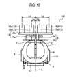
- FIGS. 9 and 10 show a third embodiment of the present invention. Same constituent components thereof as those of the first embodiment are given the same reference numerals or symbols, and the redundant description is omitted.
- a vibrating linear actuator 1B of the third embodiment basically has the substantially same structure as that of the vibrating linear actuator 1 of the first embodiment.
- the vibrating linear actuator 1B includes: the electromagnetic core blocks 3 including the electric magnet 2; and the magnetic blocks 6 each including the permanent magnet 4 and back-yoke 5.
- the magnetic blocks 6 are configured to serve as movable elements.
- the magnetic blocks 6 as the movable elements are composed of the independent first and second blocks 6a and 6b, which are provided with the first and second drive elements 13a and 13b, respectively.
- the first drive element 13a is shaped in a rectangular plate and is provided with the output portions 15a and 15b at both ends in the width direction (in the C direction).
- the second drive element 13b is placed above the upper surface of the first drive element 13a with a small gap therebetween and is shaped in a rectangular frame plate fully surrounding the first drive element 13a.
- the third and fourth output portions 15c and 15d are provided at both side edges of the second drive element 13b in the width direction (in the C direction).
- the plurality of first and second output portions 15a and 15b are substantially symmetrically placed with respect to the center-of-gravity line L
- the plurality of third and fourth output portions 15c and 15d are substantially symmetrically placed with respect to the center-of-gravity line L.
- the first and second output portions 15a and 15b are provided for the first drive element 13a
- the third and fourth output portions 15c and 15d are provided for the second drive element 13b.
- the first and second output portions 15a and 15b are substantially symmetrically placed with respect to the center-of-gravity line L
- the third and fourth output portions 15c and 15d are substantially symmetrically placed with respect to the center-of-gravity line L.
- the magnitude of the rotational moment M1 generated at the first output portion 15a placed on one side of the drive element 13 is substantially equal to the magnitude of the rotational moment M2 which is generated at the second output portion 15b placed on the other side and acts in the direction opposite to the rotational moment M1.
- the magnitude of the rotational moment M3 generated at the first output portion 15c placed on one side of the drive element 13 is substantially equal to the magnitude of the rotational moment M4 which is generated at the fourth output portion 15d placed on the other side and acts in the direction opposite to the rotational moment M3.
- the rotational moments M1 and M2 can cancel each other, and the rotational moments M3 and M4 can cancel each other, thus enhancing the effect on suppressing the vibration.
Landscapes
- Engineering & Computer Science (AREA)
- Life Sciences & Earth Sciences (AREA)
- Forests & Forestry (AREA)
- Mechanical Engineering (AREA)
- Power Engineering (AREA)
- Reciprocating, Oscillating Or Vibrating Motors (AREA)
- Apparatuses For Generation Of Mechanical Vibrations (AREA)
Applications Claiming Priority (2)
| Application Number | Priority Date | Filing Date | Title |
|---|---|---|---|
| JP2007247929A JP2009081920A (ja) | 2007-09-25 | 2007-09-25 | 振動型リニアアクチュエータ |
| PCT/JP2008/065148 WO2009041201A1 (ja) | 2007-09-25 | 2008-08-26 | 振動型リニアアクチュエータ |
Publications (2)
| Publication Number | Publication Date |
|---|---|
| EP2194635A1 true EP2194635A1 (de) | 2010-06-09 |
| EP2194635A4 EP2194635A4 (de) | 2013-11-13 |
Family
ID=40511095
Family Applications (1)
| Application Number | Title | Priority Date | Filing Date |
|---|---|---|---|
| EP08834069.0A Withdrawn EP2194635A4 (de) | 2007-09-25 | 2008-08-26 | Linearer schwingungserreger |
Country Status (4)
| Country | Link |
|---|---|
| EP (1) | EP2194635A4 (de) |
| JP (1) | JP2009081920A (de) |
| CN (1) | CN101803159A (de) |
| WO (1) | WO2009041201A1 (de) |
Cited By (4)
| Publication number | Priority date | Publication date | Assignee | Title |
|---|---|---|---|---|
| CN102958652A (zh) * | 2010-07-08 | 2013-03-06 | 松下电器产业株式会社 | 往复式电动剃刀 |
| CN102985237A (zh) * | 2010-07-08 | 2013-03-20 | 松下电器产业株式会社 | 往复式电动剃刀 |
| EP2940843A4 (de) * | 2012-12-27 | 2016-04-27 | Panasonic Ip Man Co Ltd | Elektrischer schubantrieb und elektrische ausgangswellenvibrationsvorrichtung mit besagtem elektrischen linearantrieb |
| EP3442103A1 (de) * | 2010-09-27 | 2019-02-13 | Panasonic Corporation | Linearer oszillierender aktuator |
Families Citing this family (3)
| Publication number | Priority date | Publication date | Assignee | Title |
|---|---|---|---|---|
| JP5453188B2 (ja) * | 2010-07-08 | 2014-03-26 | パナソニック株式会社 | 往復式電気かみそり |
| JP6444035B2 (ja) * | 2014-02-07 | 2018-12-26 | 国立大学法人信州大学 | 電磁振動アクチュエータ |
| CN114123702B (zh) * | 2021-12-16 | 2023-03-21 | 广东辉达电器有限公司 | 一种无刷电磁悬浮振动电机 |
Family Cites Families (8)
| Publication number | Priority date | Publication date | Assignee | Title |
|---|---|---|---|---|
| NL136196C (de) * | 1960-09-29 | |||
| JPH10156065A (ja) * | 1996-11-26 | 1998-06-16 | Matsushita Electric Works Ltd | 往復式電気かみそり |
| JP2000316267A (ja) * | 1999-04-27 | 2000-11-14 | Matsushita Electric Works Ltd | 振動型リニアアクチュエータ |
| JP3736282B2 (ja) * | 2000-04-25 | 2006-01-18 | 松下電工株式会社 | 振動型リニアアクチュエータ |
| EP1162721B1 (de) * | 2000-06-07 | 2005-12-21 | Matsushita Electric Works, Ltd. | Lineare Schwingungsvorrichtung |
| DE10242092A1 (de) * | 2002-09-11 | 2004-04-01 | Braun Gmbh | Eletrisches Kleingerät mit einer Antriebseinrichtung zur Erzeugung einer oszillierenden Bewegung |
| JP4487650B2 (ja) * | 2004-06-14 | 2010-06-23 | パナソニック電工株式会社 | 振動型リニアアクチュエータ及びこれを用いた往復式電気かみそり |
| JP4623002B2 (ja) * | 2006-12-28 | 2011-02-02 | パナソニック電工株式会社 | 振動型リニアアクチュエータ |
-
2007
- 2007-09-25 JP JP2007247929A patent/JP2009081920A/ja active Pending
-
2008
- 2008-08-26 EP EP08834069.0A patent/EP2194635A4/de not_active Withdrawn
- 2008-08-26 WO PCT/JP2008/065148 patent/WO2009041201A1/ja not_active Ceased
- 2008-08-26 CN CN200880107263.5A patent/CN101803159A/zh active Pending
Cited By (5)
| Publication number | Priority date | Publication date | Assignee | Title |
|---|---|---|---|---|
| CN102958652A (zh) * | 2010-07-08 | 2013-03-06 | 松下电器产业株式会社 | 往复式电动剃刀 |
| CN102985237A (zh) * | 2010-07-08 | 2013-03-20 | 松下电器产业株式会社 | 往复式电动剃刀 |
| EP2591894A4 (de) * | 2010-07-08 | 2013-12-04 | Panasonic Corp | Oszillierender elektrischer rasierer |
| EP3442103A1 (de) * | 2010-09-27 | 2019-02-13 | Panasonic Corporation | Linearer oszillierender aktuator |
| EP2940843A4 (de) * | 2012-12-27 | 2016-04-27 | Panasonic Ip Man Co Ltd | Elektrischer schubantrieb und elektrische ausgangswellenvibrationsvorrichtung mit besagtem elektrischen linearantrieb |
Also Published As
| Publication number | Publication date |
|---|---|
| CN101803159A (zh) | 2010-08-11 |
| WO2009041201A1 (ja) | 2009-04-02 |
| EP2194635A4 (de) | 2013-11-13 |
| JP2009081920A (ja) | 2009-04-16 |
Similar Documents
| Publication | Publication Date | Title |
|---|---|---|
| EP2194635A1 (de) | Linearer schwingungserreger | |
| EP3442103B1 (de) | Linearer oszillierender Aktuator | |
| JP3928495B2 (ja) | 振動型リニアアクチュエータ | |
| EP1332843A1 (de) | Elektrisches Haarschneidegerät | |
| JP2005185067A (ja) | 振動型リニアアクチュエータ及びこれを備えたヘアカッター | |
| KR20160038793A (ko) | 리니어 액츄에이터 및 전동 브러쉬, 전동 절삭기 및 전동 에어 펌프 | |
| CN103548248B (zh) | 线性微调电动机 | |
| US7607229B2 (en) | Electric razor | |
| US6958554B2 (en) | Reciprocating linear actuator | |
| JP2005354879A (ja) | 振動型リニアアクチュエータ及びこれを用いた往復式電気かみそり | |
| CN103973072A (zh) | 线性马达 | |
| CN1926750B (zh) | 带有一个具有磁体支架的电枢体的直线驱动装置 | |
| KR100881796B1 (ko) | 헤어 커터 | |
| KR100543098B1 (ko) | 진동형 리니어 액츄에이터 | |
| JP3841021B2 (ja) | 振動型リニアアクチュエータ | |
| JP3661370B2 (ja) | 振動型リニアアクチュエータ | |
| WO2010082515A1 (ja) | 振動型リニアアクチュエータ | |
| JP2002177665A (ja) | 往復式電気かみそり | |
| JP2005341771A (ja) | 振動型リニアアクチュエータ | |
| JP4023473B2 (ja) | 往復式電気かみそり | |
| JP2001309632A (ja) | 振動型リニアアクチュエータ | |
| JP5237784B2 (ja) | アクチュエータ | |
| JP2005160134A (ja) | 振動型リニアアクチュエータ | |
| JP2008288605A (ja) | 操作装置およびその操作装置を使用した開閉装置 | |
| JPH11276727A (ja) | 往復式電気かみそり |
Legal Events
| Date | Code | Title | Description |
|---|---|---|---|
| PUAI | Public reference made under article 153(3) epc to a published international application that has entered the european phase |
Free format text: ORIGINAL CODE: 0009012 |
|
| 17P | Request for examination filed |
Effective date: 20100308 |
|
| AK | Designated contracting states |
Kind code of ref document: A1 Designated state(s): AT BE BG CH CY CZ DE DK EE ES FI FR GB GR HR HU IE IS IT LI LT LU LV MC MT NL NO PL PT RO SE SI SK TR |
|
| AX | Request for extension of the european patent |
Extension state: AL BA MK RS |
|
| DAX | Request for extension of the european patent (deleted) | ||
| RAP1 | Party data changed (applicant data changed or rights of an application transferred) |
Owner name: PANASONIC CORPORATION |
|
| A4 | Supplementary search report drawn up and despatched |
Effective date: 20131015 |
|
| RIC1 | Information provided on ipc code assigned before grant |
Ipc: B26B 19/28 20060101ALI20131009BHEP Ipc: H02K 33/06 20060101ALI20131009BHEP Ipc: H02K 33/02 20060101AFI20131009BHEP |
|
| STAA | Information on the status of an ep patent application or granted ep patent |
Free format text: STATUS: THE APPLICATION HAS BEEN WITHDRAWN |
|
| 18W | Application withdrawn |
Effective date: 20140530 |