EP2192382B1 - Mikroelektromechanisches Gyroskop mit Rotationsantriebsbewegung und verbesserten elektrischen Eigenschaften - Google Patents
Mikroelektromechanisches Gyroskop mit Rotationsantriebsbewegung und verbesserten elektrischen Eigenschaften Download PDFInfo
- Publication number
- EP2192382B1 EP2192382B1 EP09177114A EP09177114A EP2192382B1 EP 2192382 B1 EP2192382 B1 EP 2192382B1 EP 09177114 A EP09177114 A EP 09177114A EP 09177114 A EP09177114 A EP 09177114A EP 2192382 B1 EP2192382 B1 EP 2192382B1
- Authority
- EP
- European Patent Office
- Prior art keywords
- horizontal axis
- sensing
- pair
- sensing masses
- axis
- Prior art date
- Legal status (The legal status is an assumption and is not a legal conclusion. Google has not performed a legal analysis and makes no representation as to the accuracy of the status listed.)
- Active
Links
- 238000001514 detection method Methods 0.000 claims description 37
- 239000000758 substrate Substances 0.000 claims description 12
- 230000005484 gravity Effects 0.000 claims description 11
- 239000003990 capacitor Substances 0.000 claims description 5
- 230000004044 response Effects 0.000 claims description 4
- 230000035945 sensitivity Effects 0.000 description 12
- 238000006073 displacement reaction Methods 0.000 description 10
- 230000001133 acceleration Effects 0.000 description 7
- 238000004519 manufacturing process Methods 0.000 description 3
- 239000000463 material Substances 0.000 description 3
- 239000004065 semiconductor Substances 0.000 description 3
- 238000005516 engineering process Methods 0.000 description 2
- 230000006355 external stress Effects 0.000 description 2
- 230000006872 improvement Effects 0.000 description 2
- 238000000034 method Methods 0.000 description 2
- 238000012986 modification Methods 0.000 description 2
- 230000004048 modification Effects 0.000 description 2
- 230000010355 oscillation Effects 0.000 description 2
- 229910021420 polycrystalline silicon Inorganic materials 0.000 description 2
- 230000005483 Hooke's law Effects 0.000 description 1
- 238000003486 chemical etching Methods 0.000 description 1
- 238000010276 construction Methods 0.000 description 1
- 238000010586 diagram Methods 0.000 description 1
- 238000009826 distribution Methods 0.000 description 1
- 230000036039 immunity Effects 0.000 description 1
- 238000005459 micromachining Methods 0.000 description 1
- 230000003534 oscillatory effect Effects 0.000 description 1
- 230000003071 parasitic effect Effects 0.000 description 1
- 239000011435 rock Substances 0.000 description 1
- 229910052710 silicon Inorganic materials 0.000 description 1
- 239000010703 silicon Substances 0.000 description 1
- 238000005549 size reduction Methods 0.000 description 1
Images


Classifications
-
- G—PHYSICS
- G01—MEASURING; TESTING
- G01C—MEASURING DISTANCES, LEVELS OR BEARINGS; SURVEYING; NAVIGATION; GYROSCOPIC INSTRUMENTS; PHOTOGRAMMETRY OR VIDEOGRAMMETRY
- G01C19/00—Gyroscopes; Turn-sensitive devices using vibrating masses; Turn-sensitive devices without moving masses; Measuring angular rate using gyroscopic effects
- G01C19/56—Turn-sensitive devices using vibrating masses, e.g. vibratory angular rate sensors based on Coriolis forces
- G01C19/5705—Turn-sensitive devices using vibrating masses, e.g. vibratory angular rate sensors based on Coriolis forces using masses driven in reciprocating rotary motion about an axis
- G01C19/5712—Turn-sensitive devices using vibrating masses, e.g. vibratory angular rate sensors based on Coriolis forces using masses driven in reciprocating rotary motion about an axis the devices involving a micromechanical structure
-
- Y—GENERAL TAGGING OF NEW TECHNOLOGICAL DEVELOPMENTS; GENERAL TAGGING OF CROSS-SECTIONAL TECHNOLOGIES SPANNING OVER SEVERAL SECTIONS OF THE IPC; TECHNICAL SUBJECTS COVERED BY FORMER USPC CROSS-REFERENCE ART COLLECTIONS [XRACs] AND DIGESTS
- Y10—TECHNICAL SUBJECTS COVERED BY FORMER USPC
- Y10T—TECHNICAL SUBJECTS COVERED BY FORMER US CLASSIFICATION
- Y10T29/00—Metal working
- Y10T29/49—Method of mechanical manufacture
- Y10T29/49002—Electrical device making
Definitions
- the present invention relates to a microelectromechanical structure, in particular a biaxial or triaxial gyroscope, provided with a rotary driving movement and improved electrical characteristics, in particular in terms of sensitivity in the detection of angular velocities.
- micromachining techniques enable manufacturing of microelectromechanical structures or systems (MEMS) within layers of semiconductor material, which have been deposited (for example, a polycrystalline-silicon layer) or grown (for example, an epitaxial layer) on sacrificial layers, which are removed via chemical etching.
- MEMS microelectromechanical structures or systems
- Inertial sensors, accelerometers, and gyroscopes obtained with this technology are having an increasing success, for example, in the automotive field, in inertial navigation, or in the field of portable devices.
- gyroscopes made of semiconductor material obtained with MEMS technology. These gyroscopes operate on the basis of the theorem of relative accelerations, exploiting the Coriolis acceleration.
- Coriolis force an apparent force, referred to as "Coriolis force”
- the mobile mass is supported via springs that enable a displacement thereof in the direction of the apparent force.
- the displacement is proportional to the apparent force, in such a way that from the displacement of the mobile mass it is possible to detect the Coriolis force and the value of the angular velocity that has generated it.
- the displacement of the mobile mass can, for example, be detected in a capacitive way by determining, in resonance conditions, the variations of capacitance caused by the movement of mobile electrodes, fixed with respect to the mobile mass and combfingered with fixed electrodes.
- This microelectromechanical sensor comprises a single driving mass, anchored to a substrate in a single central point, and actuated with rotary motion about an axis passing through the central point and orthogonal to the plane of the driving mass.
- the movement of rotation of the driving mass makes it possible to obtain in the plane of the mass two components of driving velocity orthogonal with respect to one another.
- Through openings are provided within the driving mass, and corresponding sensing masses are arranged in the through openings; the sensing masses are enclosed in the overall dimensions of the driving mass, are suspended with respect to the substrate, and are connected to the driving mass via flexible elements.
- Each sensing mass is fixed with respect to the driving mass during its rotary motion, and has a further degree of freedom of movement as a function of an external stress, in particular a Coriolis force, acting on the sensor.
- the flexible elements thanks to their particular construction, enable the sensing masses to perform a rotary movement of detection about an axis belonging to the plane of the sensor, or alternatively a linear movement of detection along an axis belonging to the plane of the sensor, respectively, in response to a Coriolis acceleration acting in a direction perpendicular to the plane and to a Coriolis acceleration acting in a direction belonging to the plane.
- the movement of detection is in any case substantially decoupled from the movement of actuation of the driving mass.
- This microelectromechanical structure in addition to being compact (in so far as it envisages a single driving mass enclosing in its overall dimensions a number of sensing masses), makes it possible to obtain with minor structural modifications, a uniaxial, biaxial, or triaxial gyroscope (and/or possibly an accelerometer, according to the electrical connections implemented), at the same time ensuring an excellent decoupling of the driving dynamics from the detection dynamics.
- Figure 1 shows an exemplary embodiment of a triaxial microelectromechanical gyroscope, designated by 1, according to the teachings contained in the aforesaid patent applications.
- the gyroscope 1 is made in a die 2, comprising a substrate 2a made of semiconductor material (for example, silicon), and a frame 2b defining inside it an open region 2c; the open region 2c overlies the substrate 2a, and is designed to house detection structures of the gyroscope 1 (as described in detail hereinafter).
- the open region 2c has a generally square or rectangular configuration in a horizontal plane (in what follows, plane of the sensor xy), defined by a first horizontal axis x and a second horizontal axis y, fixed with respect to the die 2.
- the frame 2b has sides that are substantially parallel to the horizontal axes x, y.
- Contact pads 2d are arranged along a side of the frame 2b, aligned, for example, along the first horizontal axis x. In a way not illustrated, the die pads 2d enable electrical contact from outside of the detection structures of the gyroscope 1.
- the die pads 2d have an axis of symmetry, in this case coinciding with the second horizontal axis y (orthogonal to their direction of alignment), and are arranged in equal number and in a specular way on opposite sides of the second horizontal axis y.
- the first and second horizontal axes x, y correspond to a first axis of detection and to a second axis of detection of the gyroscope 1 (more precisely, to a pitch axis and to a roll axis), about which corresponding pitch and roll angular velocities ⁇ z and ⁇ y are detected.
- the gyroscope 1 comprises a driving structure, housed within the open region 2c and including a driving mass 3 and a driving assembly 4.
- the driving mass 3 has a generally circular geometry with radial symmetry, with a substantially planar configuration having a main extension in the plane of the sensor xy, and a negligible dimension, with respect to the main extension, in a direction parallel to a vertical axis z, forming with the first and second horizontal axes x, y a set of three orthogonal axes, fixed with respect to the die 2.
- the driving mass 3 has in the plane of the sensor xy basically the shape of an annulus, and defines at the center an empty space 6, the center O of which coincides with the center of gravity and the center of symmetry of the entire structure.
- the driving mass 3 is anchored to the substrate 2a by means of a first anchorage 7a set in an area corresponding to the center O, to which it is connected through first elastic anchorage elements 8a.
- the first elastic anchorage elements 8a depart, forming a cross, from the center O, parallel to the first and second horizontal axes x, y.
- the driving mass 3 is anchored to the substrate 2a by means of further anchorages 7b, set on the outside of the same driving mass 3, to which it is connected by means of further elastic anchorage elements 8b.
- the further elastic anchorage elements 8b are of the folded type, are four in number, and are set aligned in pairs along the first and second horizontal axes x, y; accordingly, the further anchorages 7b are arranged, in pairs, on opposite sides of the driving mass 3 with respect to the empty space 6, at the ends of a cross centered in the center O.
- the first and further elastic anchorage elements 8a, 8b enable a rotary movement of the driving mass 3 about an axis of actuation passing through the center O, parallel to the vertical axis z and perpendicular to the plane of the sensor xy.
- the driving mass 3 has: a first pair of first through openings 9a, 9b, aligned in a diametric direction along the first horizontal axis x (pitch axis), and set on opposite sides with respect to the empty space 6; and a second pair of first through openings 9c, 9d, aligned in a diametric direction along the second horizontal axis y (roll axis), and set on opposite sides with respect to the empty space 6.
- each of the first through opening 9a-9d has in the plane of the sensor xy the shape of a radial sector of an annulus, having arc-shaped internal and external sides and radially-extending lateral sides.
- the through openings 9a-9b of the first pair are symmetrical with respect to the second horizontal axis y
- the through openings 9c-9d of the second pair are symmetrical with respect to the first horizontal axis x.
- the driving mass 3 has a pair of second through openings 26a, 26b, having in plan view a substantially rectangular shape, aligned in a radial direction (in the example of Figure 1 in a direction inclined by 45° with respect to the first horizontal axis x or the second horizontal axis y), and having a main extension in the same radial direction.
- the driving assembly 4 comprises a plurality of driven arms 10, extending externally from the driving mass 3 in a radial direction and in such a way that they are set at equal angular distances apart, and a plurality of first and second driving arms 12a, 12b, which extend parallel to, and on opposite sides of, respective driven arms 10.
- Each driven arm 10 carries a plurality of first electrodes 13, extending perpendicular to, and on either side of, the same driven arm.
- each of the first and second driving arms 12a, 12b carries respective second electrodes 14a, 14b, which extend towards the respective driven arm 10 and are combfingered with the corresponding first electrodes 13.
- the first driving arms 12a are arranged all on one and the same side of the respective driven arms 10, and are biased all at one and the same first voltage.
- the second driving arms 12b are arranged all on the opposite side of the respective driven arms 10, and are biased all at one and the same second voltage.
- a driving circuit (not illustrated) is connected to the second electrodes 14a, 14b for applying the first and second voltages and determining, by means of the mutual and alternating attraction of the electrodes, an oscillatory rotary movement of the driving mass 3 about the axis of actuation, at a given frequency of oscillation.
- the gyroscope 1 further comprises a first pair of acceleration sensors with axis parallel to the vertical axis z, and in particular a first pair of first sensing masses 16a, 16b, set within a respective first through opening 9a, 9b so as to be completely enclosed and contained within the overall dimensions of the driving mass 3 in the plane of the sensor xy.
- Each of the first sensing masses 16a, 16b has a shape corresponding to that of the respective through opening, and consequently has, in a plan view, the general shape of a radial annulus sector.
- each of the first sensing masses 16a, 16b has a first portion 17, which is wider, and a second portion 18, which is narrower (along the first horizontal axis x), these portions being connected by a connecting portion 19, which is shorter (in a direction parallel to the second horizontal axis y) than the first and second portions 17, 18, and consequently has a center of gravity G located within the corresponding first portion 17.
- the first portion 17 has an outer side that is arc-shaped and concave, and radially-extending lateral sides
- the second portion 18 has an outer side that is arc-shaped and convex and radially-extending lateral sides, aligned along the lateral sides of the first portion 17.
- Each of the first sensing masses 16a, 16b is supported by a pair of first elastic supporting elements 20, extending from the connecting portion 19 to the driving mass 3, connecting thereto, parallel to the second horizontal axis y.
- the first elastic supporting elements 20 extend within recesses 21 provided on opposite sides of the corresponding first sensing mass 16a, 16b, at a distance from its center of gravity G.
- the first elastic supporting elements 20 form torsional springs which are rigid in regard to the rotary motion of the driving mass 3 (so that the first sensing masses 16a, 16b follow the driving mass 3 in its motion of actuation), and moreover enable rotation of the first sensing masses about an axis of rotation parallel to the second horizontal axis y and belonging to the plane of the sensor xy, and hence their movement out of the plane of the sensor xy (a movement that is not, instead, allowed for the driving mass 3).
- the gyroscope 1 further comprises a second pair of acceleration sensors with axis parallel to the vertical axis z, and in particular a second pair of first sensing masses 16c, 16d, housed within the through openings 9c, 9d, and completely enclosed and contained by the driving mass 3.
- the first sensing masses 16c, 16d are obtained from the rotation through 90° of the first sensing masses 16a, 16b with respect to the center O, and consequently the corresponding elastic supporting elements 20 extend parallel to the first horizontal axis x and enable rotation out of the plane of the sensor xy, about an axis of rotation parallel to the first horizontal axis x.
- a pair of first and second sensing electrodes 22, 23 is set underneath the first and second portions 17, 18 of each of the first sensing masses 16a-16d.
- the first and second sensing electrodes 22, 23 are made of polycrystalline-silicon regions formed on the substrate 2a and having a substantially trapezoidal shape and dimensions substantially corresponding to those of the second portion 18.
- the first and second sensing electrodes 22, 23 are separated, respectively, from the first and second portions 17, 18, by an air gap, and hence form, together with the first and second portions 17, 18, respective sensing capacitors.
- the first and second sensing electrodes 22, 23 are connected to a read circuit of the gyroscope 1 (not illustrated) via the connection pads 2d.
- the gyroscope 1 further comprises a pair of second sensing masses 25a, 25b housed within the second through openings 26a, 26b.
- the second sensing masses 25a, 25b have a generally rectangular shape with sides parallel to corresponding sides of the second through openings 26a, 26b, are suspended with respect to the substrate 2a, and are connected to the driving mass 3 via second elastic supporting elements 28.
- the second elastic supporting elements 28 depart, for example, from a point set approximately at the center of the minor sides of the second sensing masses, in the radial direction.
- the second elastic supporting elements 28 are rigid with respect to the motion of actuation of the driving mass 3 (in such a way that the second sensing masses 25a, 25b follow the driving mass 3 in its rotary movement), and moreover enable a linear movement of the respective second sensing masses in the aforesaid radial direction.
- the second sensing masses 25a, 25b have prolongations 29 extending, for example, starting from a point set approximately at the centre of corresponding major sides, in a direction orthogonal to the radial direction. These prolongations 29 form sensing capacitors with plane and parallel faces with fixed electrodes anchored to the substrate, set facing, and parallel to, the same prolongations 29.
- each second sensing mass 25a, 25b departs a respective prolongation 29, which faces, and is set between, two fixed electrodes.
- first sensing electrodes 22 the fixed electrodes set in a radially more external position with respect to the center O are defined as “first sensing electrodes 22”
- second sensing electrodes 23 the fixed electrodes set in a radially more internal position are defined as “second sensing electrodes 23”.
- the gyroscope 1 is able to operate as a triaxial gyroscope, and to detect a pitch angular velocity ⁇ z about the first horizontal axis x, a roll angular velocity ⁇ y about the second horizontal axis y, and a yaw angular velocity ⁇ z about the vertical axis z.
- the rotary movement of the driving mass 3 and of the first sensing masses 16a-16d about the axis of actuation can be represented by a driving-velocity vector ⁇ a , tangential to the circumference describing the path thereof.
- the rotary motion about the first horizontal axis x or the second horizontal axis y with angular velocity ⁇ , ⁇ y causes a Coriolis force (designated by ⁇ c ) acting on the entire structure, proportional to the vector product between the angular velocity ⁇ x ⁇ y and the driving velocity v a , and hence directed along the vertical axis z.
- the configuration of the first and further elastic anchorage elements 8a, 8b is such as to inhibit, to a good approximation, the movement of the driving mass 3 out of the plane of the sensor xy, in this way enabling the effective decoupling of the motion of detection of the sensing masses with respect to that of actuation.
- the displacement of the first sensing masses 16a-16d out of the plane of the sensor xy causes a differential capacitive variation of the sensing capacitors, the value of which is proportional to the angular velocity ⁇ z , ⁇ y , which can thus be determined, in a per-se known manner via an appropriate read circuit, operating according to a differential scheme.
- the configuration in pairs of the first sensing masses 16a-16d enables automatic rejection of linear spurious accelerations along the vertical axis z.
- a rotation about the first horizontal axis x is not felt by the second pair of first sensing masses 16c, 16d, in so far as the resultant Coriolis force F c is zero (since the vector product between the angular velocity ⁇ x and the corresponding driving velocity v a goes to zero).
- the rotation about the second horizontal axis y is not felt for similar reasons by the first pair of first sensing masses 16a, 16b so that the two axes of detection are not affected and are substantially decoupled.
- an angular velocity ⁇ z to be detected acting about the vertical axis z, generates a Coriolis force F c on the second sensing masses 25a, 25b set in a radial direction (hence directed as a centrifugal force acting on the same masses), causing displacement of the second sensing masses and a capacitive variation of the corresponding sensing capacitors.
- the value of the capacitive variation is proportional to the angular velocity ⁇ z , which can be determined, in a per-se known manner, via the read circuit, operating again according to a differential scheme.
- the particular conformation of the first sensing masses 16a-16d enables an increase in the sensitivity of the gyroscope 1 (as compared to the use of other geometries for the same first sensing masses).
- the corresponding center of gravity G is positioned at a distance from the first elastic supporting elements 20 (and the corresponding axis of rotation out of the plane of the sensor xy) that is greater than that of the center of gravity of any rectangular mass that can be inscribed in one and the same sector of the driving mass 3 and is supported by elastic supporting elements extending along the same axis of rotation. Consequently, it is possible to obtain a higher twisting moment, and hence a greater movement of rotation out of the plane of the sensor xy, and in this way obtain a higher sensitivity of the sensor.
- the presence of the further elastic anchorage elements 8b, located outside the driving mass 3, enables increase of the stiffness of the driving mass 3 in regard to the movements out of the plane of the sensor xy, and so an increase in the decoupling between the driving movement and the movements of detection.
- US 2006/112764 A1 discloses an angular velocity detector having an inertial mass which is made to oscillate in a rotational direction; a detection mass is connected to the inertial mass via detecting beams, so as to displace in a vertical direction due to an angular velocity to be detected.
- US 2002/189351 A1 discloses an angular rate sensor, having a rotary drive mass, and a sense element flexibly attached to the rotary drive mass so as to rock around a sense axis in the presence of an angular velocity to be detected.
- the aim of the present invention is consequently to further improve the structure of the microelectromechanical gyroscope, in particular in regards to sensitivity to
- microelectromechanical structure as defined in claim 1, is provided according to the present invention.
- an aspect of the present invention envisages providing a microelectromechanical gyroscope having an arrangement of the sensing masses such as to enable an increase in the sensitivity of the sensor and in general an improvement of its electrical characteristics.
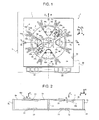
- the microelectromechanical gyroscope here designated by 30, differs from the gyroscope 1 of Figure 1 substantially on account of a different arrangement of the first sensing masses, here designated by 16a'-16d', and of the second sensing masses, here designated by 25a', 25b'.
- first sensing masses 16a', 16b' of the first pair are aligned in a first diametric direction x 1 , inclined with respect to the first horizontal axis x of the die 2 by an angle of inclination ⁇ (considered in a counterclockwise direction), the value of which is preferably 45°.
- first sensing masses 16c', 16d' of the second pair are aligned in a second diametric direction x 2 , substantially orthogonal to the first diametric direction x 1 , and inclined with respect to the first horizontal axis x by the same angle of inclination ⁇ (considered in this case in an opposite direction, namely clockwise).
- the first sensing masses 16a'-16d' are consequently aligned in respective diametric directions, which are inclined with respect to the pitch and roll axes, about which the pitch angular velocity ⁇ x and the roll angular velocity ⁇ y are applied, and moreover inclined with respect to the sides of the die 2 (and to the horizontal axes x, y).
- first sensing masses 16a', 16b' of the first pair are symmetrical to corresponding sensing masses 16d', 16c' of the second pair, with respect to the axis of symmetry of the die pads 2d (coinciding with the second horizontal axis y).
- the second sensing masses 25a'-25b' are arranged in the available space left free by the first sensing masses 16a'-16d', and are, for example, aligned along the second horizontal axis y (as illustrated in Figure 4 ). It may thus be noted that the arrangement of the first and second sensing masses in Figure 4 derives, as compared to the arrangement of the same masses of Figure 1 , from a counterclockwise rotation through the angle of inclination ⁇ about the center O.
- the present applicant has found that the aforesaid arrangement of the first and second sensing masses 16a'-16d', 25a'-25b' makes it possible to achieve a series of advantages, amongst which a simplified connection of the corresponding first and second sensing electrodes 22, 23 towards the die pads 2d.
- a first processing channel in the electronic read interface and corresponding electrical connections to the connection pads 2d are associated to the first pair of first sensing masses 16a'-16b', whilst associated to the second pair of first sensing masses 16c'-16d' are, in the same electronic read interface, a second and distinct processing channel, and corresponding electrical connections to the respective connection pads 2d.
- the present applicant has found that in the arrangement of a known type shown in Figure 1 , the position of the first sensing masses 16a-16d with respect to the connection pads 2d of the die 2 shows a marked lack of uniformity (as do the corresponding electrical connections to the same connection pads 2d).
- the two pairs of first sensing masses 16a-16d are mutually positioned in an asymmetrical way with respect to the axis of symmetry of the connection pads 2d, thus calling for a different design of the electrical connections for the two processing channels. Consequently, the reading performance referred to the two axes of detection (of pitch and roll) may be different, and possibly must be compensated for by the electronic read interface (which is consequently more complex).
- connection pads 2d the arrangement described in Figure 4 for the first sensing masses 16a'-16d' with respect to the connection pads 2d makes it possible to obtain a substantial symmetry of the electrical connections to the connection pads 2d for the two processing channels (the two pairs of first sensing masses are in fact set in an altogether symmetrical way with respect to the axis of symmetry of the connection pads 2d).
- the symmetry of the electrical connections enables, in a per-se known manner, considerable advantages to be obtained in terms of uniformity in the electrical characteristics (for example, in terms of active and parasitic capacitances, or leakage currents) and robustness to the spread of the parameters resulting from the manufacturing process.
- the arrangement described enables an increase of the symmetry also of the electrical connections referred to the second sensing masses 25a'- 25b', thus leading to an increase of uniformity in the electrical characteristics of the corresponding read electronics.
- the arrangement of the second sensing masses 25a'-25b' guarantees a substantial symmetry of the overall structure with respect to the axis of symmetry of the connection pads 2d, thus further simplifying the design of the electrical connections.
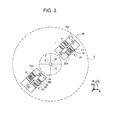
- Figure 5 shows a variant embodiment of the gyroscope 30, which differs from the one shown in Figure 4 in so far as the second sensing masses 25a'-25b' are aligned along the first horizontal axis x, instead of along the second horizontal axis y. Also in this case, the same considerations made previously still apply. In particular, this configuration intuitively enables a further increase in the symmetry of the detection structure with respect to the axis of symmetry of the die pads 2d.
- the present applicant has found that the aforesaid arrangement of the first and second sensing masses 16a'-16d', 25a'-25b' also allows to optimize exploitation of the space available in the gyroscope for detection of the angular velocity.
- the arrangement of the first sensing masses 16a'-16d' in directions inclined with respect to the sides of the frame 2b and to the horizontal axes x, y enables increase of the dimensions and maximization of the sensitivity of the first sensing masses, exploiting for detection the areas at a greater distance from the axis of rotation of actuation.
- the conformation of the first sensing masses 16a'-16d' can in this case be modified so as to improve exploitation of the space available in a radial direction, until the internal edges of the frame 2b are approached.
- the conformation of the driving mass 3 within the overall dimensions of which the sensing masses are housed is in this case modified.
- first sensing mass 16a' represented with a solid line is a variant embodiment of the first sensing mass 16a', having in this case a generally rhomboidal shape extending towards an internal edge of the frame 2b and its center of gravity G' located at an arm b c ' from the first elastic supporting elements 20.
- a first sensing mass of a traditional type for example, the first sensing mass 16b of Figure 1
- the first sensing mass 16b of a traditional type has its center of gravity G located at an arm b c from the respective first elastic supporting elements 20.
- Both of the first sensing masses illustrated are located at one and the same radial distance d between the respective first elastic supporting elements 20 and the center O.
- the arm b c of the traditional sensing mass has a value visibly smaller than that of the arm b c ' that can be obtained in the new configuration.
- the increase of the distance of the center of gravity G' of the first sensing masses 16a'-16d' from the center O enables an increase in the driving velocity v a felt by the same first sensing masses (given the same angle of rotation of the driving mass 3), and hence an increase in the Coriolis force F c ', given that this force is directly proportional to the driving velocity v a .
- the Coriolis force F c ' is applied at a greater arm b c ', the value of the resulting twisting moment increases.
- this configuration allows to have available a greater surface for the sensing electrodes 22, 23. In general, it is thus clear that this configuration enables, with appropriate design choices, a considerable increase in the sensitivity of detection.
- the present applicant has also found that the aforesaid arrangement of the first and second sensing masses 16a'-16d', 25a'-25b' makes it possible to obtain, using an appropriate configuration of the electronic read interface, a further increase in the sensitivity of the gyroscope 30.
- the gyroscope 30, shown in Figures 4 and 5 has the peculiarity of having the axes of detection in the plane of the sensor xy (coinciding with the first and second diametric directions x 1 , x 2 of alignment of the first sensing masses 16a'-16d') inclined by the angle ⁇ with respect to the horizontal axes x and y about which the pitch angular velocity ⁇ z and the roll angular velocity ⁇ y act.
- a further aspect of the present invention envisages to suitably combine at the electronic read interface level the detection signals coming from the first sensing masses 16a'-16d'.
- the detection signals are combined so as to re-obtain, starting from the capacitive variations associated to the displacements of the first sensing masses 16a'-16d', voltage outputs corresponding to the original pitch and roll directions (i.e., to the horizontal axes x and y).
- an angular velocity (of pitch or roll) about one of the horizontal axes x, y would determine a capacitive unbalancing of a single pair of first sensing masses 16a-16d (in particular the pair aligned about the same horizontal axis).
- an angular velocity (of pitch or roll) about one of the horizontal axes x, y determines a capacitive unbalancing of both of the pairs of first sensing masses 16a'-16b' and 16c'-16d', in so far as they are sensitive to the components of the angular velocities of pitch and roll along the diametric directions x 1 and x 2 , and these components have a non-zero value for both of the pairs.
- V out,x1 and V out , x2 are the output voltages corresponding to the first pair and, respectively, to the second pair of first sensing masses 16a'-16d', aligned, respectively, in the first and second diametric directions x 1 , x 2 .
- Figure 7 illustrates an electronic device 40, which comprises the microelectromechanical gyroscope 30 described previously.
- the electronic device 40 can advantageously be used in a plurality of electronic systems, for example, in inertial navigation systems, in automotive systems, or in systems of a portable type, such as, for example: a PDA (Personal Digital Assistant); a portable computer; a cellphone; a digital audio player; a photographic camera or a camcorder; or further systems capable of processing, storing, transmitting, and receiving signals and information.
- PDA Personal Digital Assistant
- the electronic device 40 further comprises: a driving circuit 41, operatively coupled to the driving assembly 4 for imparting the rotary driving movement to the driving mass 3, and supplying biasing signals to the microelectromechanical structures (in a per-se known manner, which is not illustrated in detail herein); a read circuit 42, operatively coupled to the sensing electrodes 22, 23 of the first and second sensing masses, for detecting the amount of displacement of the same sensing masses and hence determining the angular velocities acting on the structure; and an electronic control unit 44, for example, of a microprocessor type, connected to the read circuit 42, and designed to supervise the general operation of the electronic device 40, for example, on the basis of the angular velocities detected and determined.
- the read circuit 42 includes the aforesaid electronic read interface, designed to appropriately combine the output signals corresponding to the individual first sensing masses, in order to increase the sensitivity of detection, as described previously.
- microelectromechanical gyroscope provided according to the present invention are clear from the foregoing description.
- the configuration of the sensing masses makes it possible to optimize exploitation of the area available for detection, increase the sensitivity of the sensor, and improve uniformity of the electrical characteristics and the robustness of the system to disturbance. More in general, this configuration allows to improve the characteristics and the electrical performance of the microelectromechanical gyroscope.
- the new configuration of the first sensing masses can advantageously be provided for a gyroscope that is only biaxial, i.e., not sensitive to yaw angular velocity (and hence without the second sensing masses 25a'-25b').
- the value of the angle ⁇ may differ from the value described, and be, for example, comprised between 40° and 50°.
- the angles of inclination of the two pairs of first sensing masses 16a'-16d' with respect to the first horizontal axis x may also not be the same, the two pairs of first sensing masses having in any case opposite inclination with respect to the first horizontal axis x, but in this case no longer be symmetrical with respect to the second horizontal axis y.
- the two diametric directions x 1 and x 2 may not be orthogonal to one another.
- the die pads 2d can extend in a different direction, for example, along the second horizontal axis y.
- the displacement of the sensing masses can be determined with a technique different from the capacitive one, for example, by detection of a magnetic force.
- twisting moment for causing oscillation of the driving mass with rotary movement can be generated in a different way, for example, by means of parallel-plate electrodes, or else by magnetic actuation.
- the configuration of some structural elements of the gyroscope may be different.
- the driving mass 3 may have a shape different from the circular one, such as a generally closed polygonal shape, as likewise the shape of the frame 2b of the die 2 can be different.
- a different configuration of the sensing electrodes associated to the sensing masses of the first and second types can be envisaged.
Landscapes
- Physics & Mathematics (AREA)
- Engineering & Computer Science (AREA)
- General Physics & Mathematics (AREA)
- Radar, Positioning & Navigation (AREA)
- Remote Sensing (AREA)
- Gyroscopes (AREA)
Claims (15)
- Integrierte mikroelektromechanische Struktur (30), aufweisend:einen Chip (2), der ein Substrat (2a) und einen Rahmen (2b) beinhaltet, der in seinem Inneren einen Detektionsbereich (2c) bildet undeine erste Seite aufweist, die sich entlang einer ersten horizontalen Achse (x) erstreckt; eine Antriebsmasse (3), die an dem Substrat (2) über in dem Detektionsbereich (2c) vorgesehene elastische Verankerungselemente (8a, 8b) verankert ist und dazu ausgebildet ist, bei einer Betätigungsbewegung um eine vertikale Achse (z) in einer Ebene (xy) rotationsmäßig bewegt zu werden; ein erstes Paar (16a', 16b') und ein zweites Paar (16c', 16d') von ersten Sensormassen, die im Inneren der Antriebsmasse (3) schwebend gelagert und mit dieser über jeweilige elastische Stützelemente (20) gekoppelt sind, so dass sie bei der Betätigungsbewegung in Bezug auf diese festgelegt sind undeine rotationsmäßige Detektionsbewegung aus der Ebene (xy) heraus in Reaktion auf eine erste Winkelgeschwindigkeit (· x) ausführen,dadurch gekennzeichnet, dass die ersten Sensormassen des ersten Paares (16a', 16b') und die ersten Sensormassen des zweiten Paars (16c', 16d') in jeweiligen diametrischen Richtungen (x1, x2) ausgerichtet sind, die von Null verschiedene Neigungen mit entgegengesetztem Vorzeichen in Bezug auf die erste horizontale Achse aufweisen.
- Struktur nach Anspruch 1,
wobei die ersten Sensormassen des ersten Paares (16a' , 16b') in einer ersten Richtung (x1) ausgerichtet sind, die in Bezug auf die erste horizontale Achse (x) in einem Winkel (α) geneigt ist, und die ersten Sensormassen des zweiten Paars (16c', 16d') in einer zweiten Richtung (x2) ausgerichtet sind, die in dem gleichen Winkel (α) auf eine gegenüberliegende Seite in Bezug auf die erste horizontale Achse (x) geneigt ist. - Struktur nach Anspruch 2,
wobei der Winkel (α) einen Wert von im Wesentlichen gleich 45° hat und wobei die erste Richtung (X1) und der zweiten Richtung (X2) im Wesentlichen orthogonal zueinander sind. - Struktur nach einem der vorhergehenden Ansprüche,
ferner aufweisend eine Mehrzahl von Chipkontaktflächen (2d), die sich entlang der ersten Seite des Rahmens (2b) in symmetrischer Weise in Bezug auf eine zweite horizontale Achse (y) erstrecken; wobei jede der ersten Sensormassen des ersten Paares (16a', 16b') zu einer entsprechenden der ersten Sensormassen des zweiten Paars (16d', 16c') in Bezug auf die zweite horizontale Achse (y) symmetrisch angeordnet ist. - Struktur nach Anspruch 4,
wobei jeder von den ersten Sensormassen des ersten Paares (16a', 16b') und des zweiten Paares (16c', 16d') Sensorelektroden (22, 23) zugeordnet sind, die zum Bilden von Sensorkondensatoren ausgebildet sind, und wobei elektrische Verbindungen zwischen den jeweiligen Sensorelektroden (22, 23) und jeweiligen der Chipkontaktflächen (2d) vorhanden sind; wobei elektrische Verbindungen, die den ersten Sensormassen des ersten Paares (16a', 16b') zugeordnet sind, in Bezug auf die zweite horizontale Achse (y) symmetrisch mit entsprechenden elektrischen Verbindungen vorgesehen sind, die den ersten Sensormassen des zweiten Paares (16c', 16d') zugeordnet sind. - Struktur nach einem der vorhergehenden Ansprüche,
wobei der Rahmen (2b) eine zweite Seite aufweist, die sich entlang einer zweiten horizontalen Achse (y) erstreckt und eine Kante mit der ersten Seite bildet; wobei mindestens eine erste Sensormasse (16a') des ersten und des zweiten Paares derart geformt ist, dass sie sich entlang einer jeweiligen von der ersten Richtung (x1) und der zweiten Richtung (x2) bis in die Nähe der Kante erstreckt. - Struktur nach Anspruch 6,
wobei die mindestens eine erste Sensormasse (16a') eine im allgemeinen rhombische Form aufweist, die entlang der jeweiligen von der ersten Richtung (x1) und der zweiten Richtung (x2) langgestreckt ist. - Struktur nach einem der vorhergehenden Ansprüche,
wobei die erste Winkelgeschwindigkeit (· x, · y) im Einsatz um die erste horizontale Achse (x) aufgebracht wird, die mit einer ersten Detektionsachse der Struktur (30) zusammenfällt. - Struktur nach Anspruch 8 eines biaxialen Typs,
wobei die ersten Sensormassen des ersten Paares (16a', 16b') und des zweiten Paares (16c', 16d') auch dazu ausgebildet sind, die rotationsmäßige Detektionsbewegung aus der Ebene (xy) heraus in Reaktion auf eine zweite Winkelgeschwindigkeit (· y) auszuführen, die im Einsatz um eine zweite horizontale Achse (y) aufgebracht wird, die orthogonal zu der ersten horizontalen Achse (x) ist und mit einer zweiten Detektionsachse der Struktur (30) zusammenfällt. - Struktur nach Anspruch 9 eines triaxialen Typs,
weiterhin aufweisend ein Paar zweiter Sensormassen (25a', 25b'), die im Inneren der Antriebsmasse (3) schwebend gelagert sind und mit dieser über jeweilige elastische Stützelemente (28) gekoppelt sind, so dass sie bei der Betätigungsbewegung in Bezug auf diese festgelegt sind und eine lineare Detektionsbewegung in der Ebene (xy) in Reaktion auf eine weitere Winkelgeschwindigkeit (· z) ausführen, die im Einsatz um die vertikale Achse (z) aufgebracht wird; wobei die zweiten Sensormassen (25a', 25b') entlang von einer von der ersten horizontalen Achse (x) und der zweiten horizontalen Achse (y) ausgerichtet sind. - Struktur nach einem der vorhergehenden Ansprüche,
wobei der Rahmen (2b) eine allgemein quadratische oder rechteckige Form aufweist, wobei erste Seiten parallel zu der ersten horizontalen Achse (x) sind und zweite Seiten parallel zu einer zweiten horizontalen Achse (y) sind, die orthogonal zu der ersten horizontalen Achse (x) ist. - Struktur nach einem der vorhergehenden Ansprüche,
wobei die Antriebsmasse (3) im Zentrum einen leeren Raum (6) bildet und an dem Substrat (2) an einer im Zentrum (0) des leeren Raums (6) vorgesehen ersten Verankerung (7a) über erste elastische Verankerungselemente (8a), die sich in dem leeren Raum (6) erstrecken, sowie auch an weiteren Verankerungen (7b) an der Außenseite der Antriebsmasse (3) über weitere elastische Verankerungselemente (8b) verankert ist; wobei die elastischen Stützelemente (6) und die ersten (8a) sowie die weiteren (8b) elastischen Verankerungselemente derart ausgebildet sind, dass die Antriebsmasse (3) bei der rotationsmäßigen Detektionsbewegung aus der Ebene (xy) heraus von den ersten Sensormassen (16a' -16d') entkoppelt ist. - Struktur nach einem der vorhergehenden Ansprüche,
wobei die ersten Sensormassen (16a'-16d') eine solche Konformation aufweisen, dass sie einen Schwerpunkt (G') haben, der sich in einem Abstand von der Rotationsachse der rotationsmäßigen Detektionsbewegung aus der Ebene (xy) heraus befindet, der größer ist als der des Schwerpunkts (G) von einer beliebigen Sensormasse mit einer rechteckigen Form, die in die Antriebsmasse (3) eingeschrieben werden kann und durch jeweilige elastische Stützelemente zur Ausführung einer Rotationsbewegung um die Rotationsachse abgestützt ist. - Elektronische Vorrichtung (40) mit einer integrierten mikroelektromechanischen Struktur (30) nach einem der vorhergehenden Ansprüche und mit eine Lese-Stufe (42), die betriebsmäßig mit der Struktur (30) gekoppelt ist.
- Vorrichtung nach Anspruch 14,
wobei die Lese-Stufe (42) mit den Chipkontaktflächen (2d) verbunden ist, um elektrische Signale von jeder der ersten Sensormassen (16a'-16d') zu empfangen, und derart ausgebildet ist, dass sie die elektrischen Signale kombiniert und eine erste elektrische Ausgangsgröße und eine zweite elektrische Ausgangsgröße (Vout, x, Vout, y) erzeugt, die eine Funktion einer ersten Winkelgeschwindigkeit (· x), die um die erste horizontale Achse (x) aufgebracht wird, bzw. einer zweiten Winkelgeschwindigkeit (· y) sind, die um eine zweite horizontale Achse (y) aufgebracht wird, die zu der ersten horizontalen Achse (x) orthogonal ist.
Applications Claiming Priority (1)
| Application Number | Priority Date | Filing Date | Title |
|---|---|---|---|
| ITTO2008A000876A IT1391972B1 (it) | 2008-11-26 | 2008-11-26 | Giroscopio microelettromeccanico con movimento di azionamento rotatorio e migliorate caratteristiche elettriche |
Publications (2)
| Publication Number | Publication Date |
|---|---|
| EP2192382A1 EP2192382A1 (de) | 2010-06-02 |
| EP2192382B1 true EP2192382B1 (de) | 2012-08-29 |
Family
ID=41170162
Family Applications (1)
| Application Number | Title | Priority Date | Filing Date |
|---|---|---|---|
| EP09177114A Active EP2192382B1 (de) | 2008-11-26 | 2009-11-25 | Mikroelektromechanisches Gyroskop mit Rotationsantriebsbewegung und verbesserten elektrischen Eigenschaften |
Country Status (5)
| Country | Link |
|---|---|
| US (3) | US8413506B2 (de) |
| EP (1) | EP2192382B1 (de) |
| JP (1) | JP5453065B2 (de) |
| CN (1) | CN101920927B (de) |
| IT (1) | IT1391972B1 (de) |
Families Citing this family (68)
| Publication number | Priority date | Publication date | Assignee | Title |
|---|---|---|---|---|
| US8042394B2 (en) * | 2007-09-11 | 2011-10-25 | Stmicroelectronics S.R.L. | High sensitivity microelectromechanical sensor with rotary driving motion |
| IT1391972B1 (it) | 2008-11-26 | 2012-02-02 | St Microelectronics Rousset | Giroscopio microelettromeccanico con movimento di azionamento rotatorio e migliorate caratteristiche elettriche |
| ITTO20090489A1 (it) * | 2008-11-26 | 2010-12-27 | St Microelectronics Srl | Circuito di lettura per un giroscopio mems multi-asse avente direzioni di rilevamento inclinate rispetto agli assi di riferimento, e corrispondente giroscopio mems multi-asse |
| IT1391973B1 (it) | 2008-11-26 | 2012-02-02 | St Microelectronics Rousset | Giroscopio microelettromeccanico mono o biassiale con aumentata sensibilita' al rilevamento di velocita' angolari |
| IT1392741B1 (it) | 2008-12-23 | 2012-03-16 | St Microelectronics Rousset | Giroscopio microelettromeccanico con migliorata reiezione di disturbi di accelerazione |
| JP2010190706A (ja) * | 2009-02-18 | 2010-09-02 | Panasonic Corp | 慣性力センサ |
| IT1394007B1 (it) | 2009-05-11 | 2012-05-17 | St Microelectronics Rousset | Struttura microelettromeccanica con reiezione migliorata di disturbi di accelerazione |
| US8534127B2 (en) | 2009-09-11 | 2013-09-17 | Invensense, Inc. | Extension-mode angular velocity sensor |
| US9097524B2 (en) | 2009-09-11 | 2015-08-04 | Invensense, Inc. | MEMS device with improved spring system |
| ITTO20091042A1 (it) | 2009-12-24 | 2011-06-25 | St Microelectronics Srl | Giroscopio integrato microelettromeccanico con migliorata struttura di azionamento |
| DE112011103124T5 (de) | 2010-09-18 | 2013-12-19 | Fairchild Semiconductor Corporation | Biegelager zum Verringern von Quadratur für mitschwingende mikromechanische Vorrichtungen |
| WO2012037536A2 (en) | 2010-09-18 | 2012-03-22 | Fairchild Semiconductor Corporation | Packaging to reduce stress on microelectromechanical systems |
| CN103221778B (zh) * | 2010-09-18 | 2016-03-30 | 快捷半导体公司 | 具有单驱动的微机械单片式三轴陀螺仪 |
| US9278845B2 (en) | 2010-09-18 | 2016-03-08 | Fairchild Semiconductor Corporation | MEMS multi-axis gyroscope Z-axis electrode structure |
| CN103221779B (zh) | 2010-09-18 | 2017-05-31 | 快捷半导体公司 | 微机械整体式六轴惯性传感器 |
| US10065851B2 (en) | 2010-09-20 | 2018-09-04 | Fairchild Semiconductor Corporation | Microelectromechanical pressure sensor including reference capacitor |
| JP5652112B2 (ja) * | 2010-10-18 | 2015-01-14 | セイコーエプソン株式会社 | 物理量センサーおよび電子機器 |
| JP5652117B2 (ja) * | 2010-10-21 | 2015-01-14 | セイコーエプソン株式会社 | 物理量センサーおよび電子機器 |
| US9003882B1 (en) * | 2010-11-03 | 2015-04-14 | Georgia Tech Research Corporation | Vibratory tuning fork based six-degrees of freedom inertial measurement MEMS device |
| FR2974895B1 (fr) * | 2011-05-02 | 2013-06-28 | Commissariat Energie Atomique | Gyrometre a capacites parasites reduites |
| JP5287939B2 (ja) | 2011-06-28 | 2013-09-11 | 株式会社デンソー | 角速度センサ |
| ITTO20110806A1 (it) | 2011-09-12 | 2013-03-13 | St Microelectronics Srl | Dispositivo microelettromeccanico integrante un giroscopio e un accelerometro |
| US10914584B2 (en) | 2011-09-16 | 2021-02-09 | Invensense, Inc. | Drive and sense balanced, semi-coupled 3-axis gyroscope |
| US8448513B2 (en) | 2011-10-05 | 2013-05-28 | Freescale Semiconductor, Inc. | Rotary disk gyroscope |
| FR2985029B1 (fr) * | 2011-12-22 | 2014-10-24 | Commissariat Energie Atomique | Dispositif micro/nano capteur inertiel multiaxial de mouvements |
| DE102011057081A1 (de) * | 2011-12-28 | 2013-07-04 | Maxim Integrated Products, Inc. | Mikro-Drehratensensor und Verfahren zum Betreiben eines Mikro-Drehratensensors |
| US8978475B2 (en) | 2012-02-01 | 2015-03-17 | Fairchild Semiconductor Corporation | MEMS proof mass with split z-axis portions |
| JP6338813B2 (ja) * | 2012-04-03 | 2018-06-06 | セイコーエプソン株式会社 | ジャイロセンサー及びそれを用いた電子機器 |
| US9488693B2 (en) | 2012-04-04 | 2016-11-08 | Fairchild Semiconductor Corporation | Self test of MEMS accelerometer with ASICS integrated capacitors |
| EP2647955B8 (de) | 2012-04-05 | 2018-12-19 | Fairchild Semiconductor Corporation | MEMS-Vorrichtung mit Quadraturphasenverschiebungsauslöschung |
| KR102058489B1 (ko) | 2012-04-05 | 2019-12-23 | 페어차일드 세미컨덕터 코포레이션 | 멤스 장치 프론트 엔드 전하 증폭기 |
| EP2647952B1 (de) | 2012-04-05 | 2017-11-15 | Fairchild Semiconductor Corporation | Automatische Verstärkungsregelungsschleife einer MEMS-Vorrichtung für mechanischen Amplitudenantrieb |
| US9625272B2 (en) | 2012-04-12 | 2017-04-18 | Fairchild Semiconductor Corporation | MEMS quadrature cancellation and signal demodulation |
| JP6191151B2 (ja) * | 2012-05-29 | 2017-09-06 | 株式会社デンソー | 物理量センサ |
| JP5822321B2 (ja) * | 2012-06-22 | 2015-11-24 | 国立研究開発法人産業技術総合研究所 | 回転角加速度測定装置 |
| DE102013014881B4 (de) | 2012-09-12 | 2023-05-04 | Fairchild Semiconductor Corporation | Verbesserte Silizium-Durchkontaktierung mit einer Füllung aus mehreren Materialien |
| KR101961478B1 (ko) * | 2012-09-19 | 2019-03-22 | 엘지이노텍 주식회사 | 카메라 모듈 |
| US9547095B2 (en) | 2012-12-19 | 2017-01-17 | Westerngeco L.L.C. | MEMS-based rotation sensor for seismic applications and sensor units having same |
| JP6339669B2 (ja) | 2013-07-08 | 2018-06-06 | モーション・エンジン・インコーポレーテッド | Memsデバイスおよび製造する方法 |
| US10273147B2 (en) | 2013-07-08 | 2019-04-30 | Motion Engine Inc. | MEMS components and method of wafer-level manufacturing thereof |
| WO2015013828A1 (en) | 2013-08-02 | 2015-02-05 | Motion Engine Inc. | Mems motion sensor and method of manufacturing |
| US9404747B2 (en) | 2013-10-30 | 2016-08-02 | Stmicroelectroncs S.R.L. | Microelectromechanical gyroscope with compensation of quadrature error drift |
| WO2015103688A1 (en) | 2014-01-09 | 2015-07-16 | Motion Engine Inc. | Integrated mems system |
| US20170030788A1 (en) | 2014-04-10 | 2017-02-02 | Motion Engine Inc. | Mems pressure sensor |
| CN105043370B (zh) | 2014-04-29 | 2019-01-22 | 财团法人工业技术研究院 | 具有支点元件的微型电机装置 |
| US9726493B2 (en) * | 2014-05-16 | 2017-08-08 | Hanking Electronics, Ltd. | Shock-robust integrated multi-axis MEMS gyroscope |
| EP4166903A1 (de) * | 2014-05-21 | 2023-04-19 | InvenSense, Inc. | Mems-sensor mit entkoppeltem antriebssystem |
| WO2015184531A1 (en) | 2014-06-02 | 2015-12-10 | Motion Engine Inc. | Multi-mass mems motion sensor |
| US11287486B2 (en) | 2014-12-09 | 2022-03-29 | Motion Engine, Inc. | 3D MEMS magnetometer and associated methods |
| CA3220839A1 (en) | 2015-01-15 | 2016-07-21 | Motion Engine Inc. | 3d mems device with hermetic cavity |
| FI127202B (en) * | 2015-04-16 | 2018-01-31 | Murata Manufacturing Co | Three axis gyroscope |
| DE102015211387A1 (de) * | 2015-06-19 | 2016-12-22 | Robert Bosch Gmbh | Drei-achsiger Drehbeschleunigungssensor |
| ITUA20161498A1 (it) * | 2016-03-09 | 2017-09-09 | St Microelectronics Srl | Struttura di rilevamento micromeccanica di un dispositivo sensore mems, in particolare di un giroscopio mems, con migliorate caratteristiche di azionamento |
| ITUA20162172A1 (it) | 2016-03-31 | 2017-10-01 | St Microelectronics Srl | Sensore accelerometrico realizzato in tecnologia mems avente elevata accuratezza e ridotta sensibilita' nei confronti della temperatura e dell'invecchiamento |
| US10371521B2 (en) | 2016-05-26 | 2019-08-06 | Honeywell International Inc. | Systems and methods for a four-mass vibrating MEMS structure |
| US10696541B2 (en) | 2016-05-26 | 2020-06-30 | Honeywell International Inc. | Systems and methods for bias suppression in a non-degenerate MEMS sensor |
| US10697994B2 (en) | 2017-02-22 | 2020-06-30 | Semiconductor Components Industries, Llc | Accelerometer techniques to compensate package stress |
| CN107796383B (zh) * | 2017-10-17 | 2021-03-23 | 西北工业大学 | 芯片级旋转调制式mems硅微机械陀螺 |
| JP6849042B2 (ja) | 2018-12-19 | 2021-03-24 | 株式会社村田製作所 | 振動に強い多軸ジャイロスコープ |
| EP3671116B1 (de) * | 2018-12-19 | 2021-11-17 | Murata Manufacturing Co., Ltd. | Synchronisiertes gyroskop mit mehreren achsen |
| CN113196009A (zh) * | 2019-01-08 | 2021-07-30 | 松下知识产权经营株式会社 | 感测设备 |
| WO2020258177A1 (zh) * | 2019-06-27 | 2020-12-30 | 瑞声声学科技(深圳)有限公司 | 一种差分谐振器及mems传感器 |
| JP7188311B2 (ja) | 2019-07-31 | 2022-12-13 | セイコーエプソン株式会社 | ジャイロセンサー、電子機器、及び移動体 |
| IT201900017546A1 (it) | 2019-09-30 | 2021-03-30 | St Microelectronics Srl | Dispositivo a pulsante mems resistente all'acqua, dispositivo di ingresso comprendente il dispositivo a pulsante mems e apparecchio elettronico |
| CN110779510B (zh) * | 2019-11-14 | 2021-07-13 | 无锡莱斯能特科技有限公司 | 一种三轴mems陀螺仪 |
| DE102020205369A1 (de) * | 2020-04-28 | 2021-10-28 | Robert Bosch Gesellschaft mit beschränkter Haftung | Mikromechanisches Bauteil für einen Drehratensensor und entsprechendes Herstellungsverfahren |
| US11525680B2 (en) * | 2021-02-17 | 2022-12-13 | Nxp Usa, Inc. | Angular rate sensor with centrally positioned coupling structures |
| CN114353776A (zh) * | 2021-12-31 | 2022-04-15 | 瑞声开泰科技(武汉)有限公司 | 一种基于旋转模态的mems陀螺 |
Family Cites Families (87)
| Publication number | Priority date | Publication date | Assignee | Title |
|---|---|---|---|---|
| US572936A (en) * | 1896-12-08 | John thomas waters and guy clopton | ||
| US4159125A (en) | 1977-11-04 | 1979-06-26 | General Motors Corporation | Uncoupled strut suspension system |
| US4744248A (en) | 1985-07-25 | 1988-05-17 | Litton Systems, Inc. | Vibrating accelerometer-multisensor |
| JPS6293668A (ja) | 1985-10-21 | 1987-04-30 | Hitachi Ltd | 角速度・加速度検出器 |
| US5205171A (en) | 1991-01-11 | 1993-04-27 | Northrop Corporation | Miniature silicon accelerometer and method |
| US5447068A (en) | 1994-03-31 | 1995-09-05 | Ford Motor Company | Digital capacitive accelerometer |
| DE4414237A1 (de) | 1994-04-23 | 1995-10-26 | Bosch Gmbh Robert | Mikromechanischer Schwinger eines Schwingungsgyrometers |
| DE19530007C2 (de) | 1995-08-16 | 1998-11-26 | Bosch Gmbh Robert | Drehratensensor |
| US6250156B1 (en) | 1996-05-31 | 2001-06-26 | The Regents Of The University Of California | Dual-mass micromachined vibratory rate gyroscope |
| DE19641284C1 (de) | 1996-10-07 | 1998-05-20 | Inst Mikro Und Informationstec | Drehratensensor mit entkoppelten orthogonalen Primär- und Sekundärschwingungen |
| US6230563B1 (en) | 1998-06-09 | 2001-05-15 | Integrated Micro Instruments, Inc. | Dual-mass vibratory rate gyroscope with suppressed translational acceleration response and quadrature-error correction capability |
| JP3796991B2 (ja) | 1998-12-10 | 2006-07-12 | 株式会社デンソー | 角速度センサ |
| DE19938206A1 (de) | 1999-08-12 | 2001-02-15 | Bosch Gmbh Robert | Mikromechanischer Drehbeschleunigungssensor |
| JP3589182B2 (ja) | 2000-07-07 | 2004-11-17 | 株式会社村田製作所 | 外力計測装置 |
| DE10108196A1 (de) | 2001-02-21 | 2002-10-24 | Bosch Gmbh Robert | Drehratensensor |
| US6928872B2 (en) | 2001-04-27 | 2005-08-16 | Stmicroelectronics S.R.L. | Integrated gyroscope of semiconductor material with at least one sensitive axis in the sensor plane |
| DE60120921T2 (de) | 2001-04-27 | 2007-02-01 | Stmicroelectronics S.R.L., Agrate Brianza | Aus Halbleitermaterial hergestellter integrierter Kreisel |
| US6535800B2 (en) | 2001-05-29 | 2003-03-18 | Delphi Technologies, Inc. | Vehicle rollover sensing using angular rate sensors |
| US20020189351A1 (en) * | 2001-06-14 | 2002-12-19 | Reeds John W. | Angular rate sensor having a sense element constrained to motion about a single axis and flexibly attached to a rotary drive mass |
| US6722197B2 (en) | 2001-06-19 | 2004-04-20 | Honeywell International Inc. | Coupled micromachined structure |
| US6513380B2 (en) | 2001-06-19 | 2003-02-04 | Microsensors, Inc. | MEMS sensor with single central anchor and motion-limiting connection geometry |
| JP3870895B2 (ja) | 2002-01-10 | 2007-01-24 | 株式会社村田製作所 | 角速度センサ |
| US6725719B2 (en) | 2002-04-17 | 2004-04-27 | Milli Sensor Systems And Actuators, Inc. | MEMS-integrated inertial measurement units on a common substrate |
| FI119159B (fi) | 2003-02-11 | 2008-08-15 | Vti Technologies Oy | Kapasitiivinen kiihtyvyysanturirakenne |
| US6845665B2 (en) | 2003-04-28 | 2005-01-25 | Analog Devices, Inc. | Micro-machined multi-sensor providing 2-axes of acceleration sensing and 1-axis of angular rate sensing |
| US6837107B2 (en) | 2003-04-28 | 2005-01-04 | Analog Devices, Inc. | Micro-machined multi-sensor providing 1-axis of acceleration sensing and 2-axes of angular rate sensing |
| US6848304B2 (en) | 2003-04-28 | 2005-02-01 | Analog Devices, Inc. | Six degree-of-freedom micro-machined multi-sensor |
| FR2858853B1 (fr) | 2003-08-13 | 2006-01-13 | Sercel Rech Const Elect | Accelerometre a vibrations parasites reduites par forme des electrodes amelioree |
| FR2859528B1 (fr) | 2003-09-09 | 2006-01-06 | Thales Sa | Gyrometre micro-usine a double diapason et a detection dans le plan de la plaque usinee |
| JP2005241500A (ja) | 2004-02-27 | 2005-09-08 | Mitsubishi Electric Corp | 角速度センサ |
| WO2005103620A1 (en) | 2004-04-14 | 2005-11-03 | Analog Devices, Inc. | Inertial sensor with a linear array of sensor elements |
| KR100652952B1 (ko) | 2004-07-19 | 2006-12-06 | 삼성전자주식회사 | 커플링 스프링을 구비한 멤스 자이로스코프 |
| EP1624286B1 (de) | 2004-08-03 | 2017-10-04 | STMicroelectronics Srl | Mikroelektromechanischer Sensor mit Kraft-Rückkopplungsschleife |
| EP1626283B1 (de) | 2004-08-13 | 2011-03-23 | STMicroelectronics Srl | Mikroelektromechanische Struktur, insbesondere Beschleunigungssensor, mit verbesserter Unempfindlichkeit gegenüber thermischen und mechanischen Spannungen |
| DE112005002196B4 (de) | 2004-09-27 | 2023-12-21 | Conti Temic Microelectronic Gmbh | Drehratensensor |
| SE528404C2 (sv) | 2004-10-20 | 2006-11-07 | Imego Ab | Sensorarrangemang |
| JP4353087B2 (ja) * | 2004-12-01 | 2009-10-28 | 株式会社デンソー | 回転振動型角速度センサ |
| US7155976B2 (en) | 2005-01-05 | 2007-01-02 | Industrial Technology Research Institute | Rotation sensing apparatus and method for manufacturing the same |
| US7240552B2 (en) | 2005-06-06 | 2007-07-10 | Bei Technologies, Inc. | Torsional rate sensor with momentum balance and mode decoupling |
| JP2007071677A (ja) | 2005-09-07 | 2007-03-22 | Hitachi Ltd | コンバインドセンサとその製造方法 |
| US7454246B2 (en) | 2005-09-08 | 2008-11-18 | Massachusetts Eye & Ear Infirmary | Sensor signal alignment |
| JP4887034B2 (ja) | 2005-12-05 | 2012-02-29 | 日立オートモティブシステムズ株式会社 | 慣性センサ |
| US8113050B2 (en) | 2006-01-25 | 2012-02-14 | The Regents Of The University Of California | Robust six degree-of-freedom micromachined gyroscope with anti-phase drive scheme and method of operation of the same |
| EP1832841B1 (de) * | 2006-03-10 | 2015-12-30 | STMicroelectronics Srl | Mikroelektromechanische integrierte Sensorstruktur mit Rotationsantriebsbewegung |
| KR20090052832A (ko) | 2006-03-10 | 2009-05-26 | 콘티넨탈 테베스 아게 운트 코. 오하게 | 커플링 바를 구비한 회전 속도 센서 |
| JP4687577B2 (ja) | 2006-06-16 | 2011-05-25 | ソニー株式会社 | 慣性センサ |
| DE102006046772A1 (de) * | 2006-09-29 | 2008-04-03 | Siemens Ag | Anordnung zur Messung einer Drehrate mit einem Vibrationssensor |
| US7461552B2 (en) | 2006-10-23 | 2008-12-09 | Custom Sensors & Technologies, Inc. | Dual axis rate sensor |
| JP2008129088A (ja) | 2006-11-16 | 2008-06-05 | Eastman Kodak Co | 角速度検出システムを備えるカメラの誤差除去方法 |
| US7934423B2 (en) | 2007-12-10 | 2011-05-03 | Invensense, Inc. | Vertically integrated 3-axis MEMS angular accelerometer with integrated electronics |
| US8020441B2 (en) | 2008-02-05 | 2011-09-20 | Invensense, Inc. | Dual mode sensing for vibratory gyroscope |
| US8250921B2 (en) | 2007-07-06 | 2012-08-28 | Invensense, Inc. | Integrated motion processing unit (MPU) with MEMS inertial sensing and embedded digital electronics |
| EP1962054B1 (de) | 2007-02-13 | 2011-07-20 | STMicroelectronics Srl | Mikroelektromechanisches Gyroskop mit Detektionsvorrichtung mit offenem Regelkreis und Verfahren zur Steuerung eines mikroelektromechanischen Gyroskops |
| US7950281B2 (en) | 2007-02-28 | 2011-05-31 | Infineon Technologies Ag | Sensor and method for sensing linear acceleration and angular velocity |
| DE102007030119A1 (de) | 2007-06-29 | 2009-01-02 | Litef Gmbh | Corioliskreisel |
| KR100885416B1 (ko) | 2007-07-19 | 2009-02-24 | 건국대학교 산학협력단 | 일체형 가속도계·각속도계 구동 시스템 |
| DE102007035806B4 (de) | 2007-07-31 | 2011-03-17 | Sensordynamics Ag | Mikromechanischer Drehratensensor |
| DE102007057042A1 (de) | 2007-09-10 | 2009-03-12 | Continental Teves Ag & Co. Ohg | Mikromechanischer Drehratensensor mit Kopplungsbalken und Aufhängungs-Federelementen zur Unterdrückung der Quadratur |
| US8042394B2 (en) | 2007-09-11 | 2011-10-25 | Stmicroelectronics S.R.L. | High sensitivity microelectromechanical sensor with rotary driving motion |
| GB0720412D0 (en) | 2007-10-18 | 2007-11-28 | Melexis Nv | Combined mems accelerometer and gyroscope |
| DE102007054505B4 (de) | 2007-11-15 | 2016-12-22 | Robert Bosch Gmbh | Drehratensensor |
| US8037757B2 (en) | 2007-12-12 | 2011-10-18 | Honeywell International Inc. | Parametric amplification of a MEMS gyroscope by capacitance modulation |
| CN101910789B (zh) | 2008-01-07 | 2012-02-29 | 株式会社村田制作所 | 角速度传感器 |
| US7984648B2 (en) | 2008-04-10 | 2011-07-26 | Honeywell International Inc. | Systems and methods for acceleration and rotational determination from an in-plane and out-of-plane MEMS device |
| DE102008002748A1 (de) | 2008-06-27 | 2009-12-31 | Sensordynamics Ag | Mikro-Gyroskop |
| JP2010071793A (ja) | 2008-09-18 | 2010-04-02 | Toshiba Corp | 多軸加速度センサ及び角速度センサ |
| ITTO20090489A1 (it) | 2008-11-26 | 2010-12-27 | St Microelectronics Srl | Circuito di lettura per un giroscopio mems multi-asse avente direzioni di rilevamento inclinate rispetto agli assi di riferimento, e corrispondente giroscopio mems multi-asse |
| IT1391972B1 (it) | 2008-11-26 | 2012-02-02 | St Microelectronics Rousset | Giroscopio microelettromeccanico con movimento di azionamento rotatorio e migliorate caratteristiche elettriche |
| IT1391973B1 (it) | 2008-11-26 | 2012-02-02 | St Microelectronics Rousset | Giroscopio microelettromeccanico mono o biassiale con aumentata sensibilita' al rilevamento di velocita' angolari |
| IT1392553B1 (it) | 2008-12-11 | 2012-03-09 | St Microelectronics Rousset | Dispositivo elettronico a capacita' variabile e dispositivo microelettromeccanico incorporante tale dispositivo elettronico |
| IT1392741B1 (it) | 2008-12-23 | 2012-03-16 | St Microelectronics Rousset | Giroscopio microelettromeccanico con migliorata reiezione di disturbi di accelerazione |
| DE102009000606A1 (de) | 2009-02-04 | 2010-08-05 | Robert Bosch Gmbh | Mikromechanische Strukturen |
| DE102009001244A1 (de) | 2009-02-27 | 2010-09-02 | Sensordynamics Ag | Mikro-Gyroskop zur Ermittlung von Rotationsbewegungen um eine x-, y- oder z-Achse |
| US8256290B2 (en) | 2009-03-17 | 2012-09-04 | Minyao Mao | Tri-axis angular rate sensor |
| DE102009001922A1 (de) | 2009-03-26 | 2010-09-30 | Sensordynamics Ag | Mikro-Gyroskop zur Ermittlung von Rotationsbewegungen um drei senkrecht aufeinanderstehende Raumachsen x, y und z |
| IT1394007B1 (it) | 2009-05-11 | 2012-05-17 | St Microelectronics Rousset | Struttura microelettromeccanica con reiezione migliorata di disturbi di accelerazione |
| IT1394898B1 (it) | 2009-06-03 | 2012-07-20 | St Microelectronics Rousset | Giroscopio microelettromeccanico con attuazione a controllo di posizione e metodo per il controllo di un giroscopio microelettromeccanico |
| US8710599B2 (en) | 2009-08-04 | 2014-04-29 | Fairchild Semiconductor Corporation | Micromachined devices and fabricating the same |
| US8534127B2 (en) | 2009-09-11 | 2013-09-17 | Invensense, Inc. | Extension-mode angular velocity sensor |
| ITTO20091042A1 (it) | 2009-12-24 | 2011-06-25 | St Microelectronics Srl | Giroscopio integrato microelettromeccanico con migliorata struttura di azionamento |
| US8616057B1 (en) | 2010-01-23 | 2013-12-31 | Minyao Mao | Angular rate sensor with suppressed linear acceleration response |
| US8317104B2 (en) | 2010-08-05 | 2012-11-27 | Hand Held Products, Inc. | Image engine with integrated circuit structure for indicia reading terminal |
| US9003882B1 (en) | 2010-11-03 | 2015-04-14 | Georgia Tech Research Corporation | Vibratory tuning fork based six-degrees of freedom inertial measurement MEMS device |
| JP5822177B2 (ja) | 2011-05-20 | 2015-11-24 | セイコーエプソン株式会社 | ジャイロセンサー、電子機器 |
| WO2012161690A1 (en) | 2011-05-23 | 2012-11-29 | Senodia Technologies (Shanghai) Co., Ltd. | Mems devices sensing both rotation and acceleration |
| DE102011057081A1 (de) | 2011-12-28 | 2013-07-04 | Maxim Integrated Products, Inc. | Mikro-Drehratensensor und Verfahren zum Betreiben eines Mikro-Drehratensensors |
| US9194704B2 (en) | 2013-03-13 | 2015-11-24 | Freescale Semiconductor, Inc. | Angular rate sensor having multiple axis sensing capability |
-
2008
- 2008-11-26 IT ITTO2008A000876A patent/IT1391972B1/it active
-
2009
- 2009-11-25 US US12/626,433 patent/US8413506B2/en active Active
- 2009-11-25 EP EP09177114A patent/EP2192382B1/de active Active
- 2009-11-25 JP JP2009268139A patent/JP5453065B2/ja active Active
- 2009-11-26 CN CN200910258473.0A patent/CN101920927B/zh active Active
-
2013
- 2013-03-07 US US13/789,476 patent/US8733172B2/en active Active
-
2014
- 2014-04-30 US US14/266,676 patent/US9470526B2/en active Active
Also Published As
| Publication number | Publication date |
|---|---|
| US8413506B2 (en) | 2013-04-09 |
| US20130180334A1 (en) | 2013-07-18 |
| CN101920927A (zh) | 2010-12-22 |
| US8733172B2 (en) | 2014-05-27 |
| IT1391972B1 (it) | 2012-02-02 |
| ITTO20080876A1 (it) | 2010-05-27 |
| CN101920927B (zh) | 2014-06-18 |
| EP2192382A1 (de) | 2010-06-02 |
| JP2010151808A (ja) | 2010-07-08 |
| US20140230548A1 (en) | 2014-08-21 |
| JP5453065B2 (ja) | 2014-03-26 |
| US9470526B2 (en) | 2016-10-18 |
| US20100126269A1 (en) | 2010-05-27 |
Similar Documents
| Publication | Publication Date | Title |
|---|---|---|
| EP2192382B1 (de) | Mikroelektromechanisches Gyroskop mit Rotationsantriebsbewegung und verbesserten elektrischen Eigenschaften | |
| EP2192383B1 (de) | Einachsiges oder zweiachsiges mikroelektromechanisches Gyroskop mit verbesserter Empfindlichkeit der Winkelgeschwindigkeitsdetektion | |
| USRE45792E1 (en) | High sensitivity microelectromechanical sensor with driving motion | |
| US7694563B2 (en) | Microelectromechanical integrated sensor structure with rotary driving motion | |
| US8549917B2 (en) | Microelectromechanical gyroscope with enhanced rejection of acceleration noises | |
| EP2462408B1 (de) | Mikromechanisch hergestellte trägheitssensorvorrichtungen | |
| US6513380B2 (en) | MEMS sensor with single central anchor and motion-limiting connection geometry | |
| US9068834B2 (en) | Double-axial, shock-resistant rotation rate sensor with nested, linearly oscillating seismic elements | |
| US7617728B2 (en) | Tuning fork gyroscope | |
| US6859751B2 (en) | Planar inertial measurement units based on gyros and accelerometers with a common structure | |
| US11015933B2 (en) | Micromechanical detection structure for a MEMS sensor device, in particular a MEMS gyroscope, with improved driving features | |
| US20120210789A1 (en) | Physical quantity sensor and electronic device | |
| US20130239679A1 (en) | Three-axis gyroscope | |
| US11226202B2 (en) | Three-axis micromechanical rotation rate sensor system including linearly and rotatorily drivable sensor units | |
| JP3421340B2 (ja) | 強誘電薄膜進行波回転センサ |
Legal Events
| Date | Code | Title | Description |
|---|---|---|---|
| PUAI | Public reference made under article 153(3) epc to a published international application that has entered the european phase |
Free format text: ORIGINAL CODE: 0009012 |
|
| AK | Designated contracting states |
Kind code of ref document: A1 Designated state(s): AT BE BG CH CY CZ DE DK EE ES FI FR GB GR HR HU IE IS IT LI LT LU LV MC MK MT NL NO PL PT RO SE SI SK SM TR |
|
| AX | Request for extension of the european patent |
Extension state: AL BA RS |
|
| 17P | Request for examination filed |
Effective date: 20101201 |
|
| 17Q | First examination report despatched |
Effective date: 20110111 |
|
| GRAP | Despatch of communication of intention to grant a patent |
Free format text: ORIGINAL CODE: EPIDOSNIGR1 |
|
| RAP1 | Party data changed (applicant data changed or rights of an application transferred) |
Owner name: STMICROELECTRONICS SRL |
|
| GRAS | Grant fee paid |
Free format text: ORIGINAL CODE: EPIDOSNIGR3 |
|
| GRAA | (expected) grant |
Free format text: ORIGINAL CODE: 0009210 |
|
| AK | Designated contracting states |
Kind code of ref document: B1 Designated state(s): AT BE BG CH CY CZ DE DK EE ES FI FR GB GR HR HU IE IS IT LI LT LU LV MC MK MT NL NO PL PT RO SE SI SK SM TR |
|
| REG | Reference to a national code |
Ref country code: GB Ref legal event code: FG4D |
|
| REG | Reference to a national code |
Ref country code: CH Ref legal event code: EP |
|
| REG | Reference to a national code |
Ref country code: AT Ref legal event code: REF Ref document number: 573295 Country of ref document: AT Kind code of ref document: T Effective date: 20120915 |
|
| REG | Reference to a national code |
Ref country code: IE Ref legal event code: FG4D |
|
| REG | Reference to a national code |
Ref country code: DE Ref legal event code: R096 Ref document number: 602009009232 Country of ref document: DE Effective date: 20121025 |
|
| REG | Reference to a national code |
Ref country code: AT Ref legal event code: MK05 Ref document number: 573295 Country of ref document: AT Kind code of ref document: T Effective date: 20120829 |
|
| REG | Reference to a national code |
Ref country code: NL Ref legal event code: VDEP Effective date: 20120829 |
|
| REG | Reference to a national code |
Ref country code: LT Ref legal event code: MG4D Effective date: 20120829 |
|
| PG25 | Lapsed in a contracting state [announced via postgrant information from national office to epo] |
Ref country code: NO Free format text: LAPSE BECAUSE OF FAILURE TO SUBMIT A TRANSLATION OF THE DESCRIPTION OR TO PAY THE FEE WITHIN THE PRESCRIBED TIME-LIMIT Effective date: 20121129 Ref country code: AT Free format text: LAPSE BECAUSE OF FAILURE TO SUBMIT A TRANSLATION OF THE DESCRIPTION OR TO PAY THE FEE WITHIN THE PRESCRIBED TIME-LIMIT Effective date: 20120829 Ref country code: LT Free format text: LAPSE BECAUSE OF FAILURE TO SUBMIT A TRANSLATION OF THE DESCRIPTION OR TO PAY THE FEE WITHIN THE PRESCRIBED TIME-LIMIT Effective date: 20120829 Ref country code: FI Free format text: LAPSE BECAUSE OF FAILURE TO SUBMIT A TRANSLATION OF THE DESCRIPTION OR TO PAY THE FEE WITHIN THE PRESCRIBED TIME-LIMIT Effective date: 20120829 Ref country code: HR Free format text: LAPSE BECAUSE OF FAILURE TO SUBMIT A TRANSLATION OF THE DESCRIPTION OR TO PAY THE FEE WITHIN THE PRESCRIBED TIME-LIMIT Effective date: 20120829 Ref country code: CY Free format text: LAPSE BECAUSE OF FAILURE TO SUBMIT A TRANSLATION OF THE DESCRIPTION OR TO PAY THE FEE WITHIN THE PRESCRIBED TIME-LIMIT Effective date: 20120829 Ref country code: IS Free format text: LAPSE BECAUSE OF FAILURE TO SUBMIT A TRANSLATION OF THE DESCRIPTION OR TO PAY THE FEE WITHIN THE PRESCRIBED TIME-LIMIT Effective date: 20121229 |
|
| PG25 | Lapsed in a contracting state [announced via postgrant information from national office to epo] |
Ref country code: SE Free format text: LAPSE BECAUSE OF FAILURE TO SUBMIT A TRANSLATION OF THE DESCRIPTION OR TO PAY THE FEE WITHIN THE PRESCRIBED TIME-LIMIT Effective date: 20120829 Ref country code: BE Free format text: LAPSE BECAUSE OF FAILURE TO SUBMIT A TRANSLATION OF THE DESCRIPTION OR TO PAY THE FEE WITHIN THE PRESCRIBED TIME-LIMIT Effective date: 20120829 Ref country code: GR Free format text: LAPSE BECAUSE OF FAILURE TO SUBMIT A TRANSLATION OF THE DESCRIPTION OR TO PAY THE FEE WITHIN THE PRESCRIBED TIME-LIMIT Effective date: 20121130 Ref country code: SI Free format text: LAPSE BECAUSE OF FAILURE TO SUBMIT A TRANSLATION OF THE DESCRIPTION OR TO PAY THE FEE WITHIN THE PRESCRIBED TIME-LIMIT Effective date: 20120829 Ref country code: LV Free format text: LAPSE BECAUSE OF FAILURE TO SUBMIT A TRANSLATION OF THE DESCRIPTION OR TO PAY THE FEE WITHIN THE PRESCRIBED TIME-LIMIT Effective date: 20120829 Ref country code: PT Free format text: LAPSE BECAUSE OF FAILURE TO SUBMIT A TRANSLATION OF THE DESCRIPTION OR TO PAY THE FEE WITHIN THE PRESCRIBED TIME-LIMIT Effective date: 20121231 |
|
| PG25 | Lapsed in a contracting state [announced via postgrant information from national office to epo] |
Ref country code: ES Free format text: LAPSE BECAUSE OF FAILURE TO SUBMIT A TRANSLATION OF THE DESCRIPTION OR TO PAY THE FEE WITHIN THE PRESCRIBED TIME-LIMIT Effective date: 20121210 Ref country code: RO Free format text: LAPSE BECAUSE OF FAILURE TO SUBMIT A TRANSLATION OF THE DESCRIPTION OR TO PAY THE FEE WITHIN THE PRESCRIBED TIME-LIMIT Effective date: 20120829 Ref country code: DK Free format text: LAPSE BECAUSE OF FAILURE TO SUBMIT A TRANSLATION OF THE DESCRIPTION OR TO PAY THE FEE WITHIN THE PRESCRIBED TIME-LIMIT Effective date: 20120829 Ref country code: CZ Free format text: LAPSE BECAUSE OF FAILURE TO SUBMIT A TRANSLATION OF THE DESCRIPTION OR TO PAY THE FEE WITHIN THE PRESCRIBED TIME-LIMIT Effective date: 20120829 Ref country code: NL Free format text: LAPSE BECAUSE OF FAILURE TO SUBMIT A TRANSLATION OF THE DESCRIPTION OR TO PAY THE FEE WITHIN THE PRESCRIBED TIME-LIMIT Effective date: 20120829 Ref country code: EE Free format text: LAPSE BECAUSE OF FAILURE TO SUBMIT A TRANSLATION OF THE DESCRIPTION OR TO PAY THE FEE WITHIN THE PRESCRIBED TIME-LIMIT Effective date: 20120829 |
|
| PG25 | Lapsed in a contracting state [announced via postgrant information from national office to epo] |
Ref country code: SK Free format text: LAPSE BECAUSE OF FAILURE TO SUBMIT A TRANSLATION OF THE DESCRIPTION OR TO PAY THE FEE WITHIN THE PRESCRIBED TIME-LIMIT Effective date: 20120829 Ref country code: PL Free format text: LAPSE BECAUSE OF FAILURE TO SUBMIT A TRANSLATION OF THE DESCRIPTION OR TO PAY THE FEE WITHIN THE PRESCRIBED TIME-LIMIT Effective date: 20120829 |
|
| PLBE | No opposition filed within time limit |
Free format text: ORIGINAL CODE: 0009261 |
|
| STAA | Information on the status of an ep patent application or granted ep patent |
Free format text: STATUS: NO OPPOSITION FILED WITHIN TIME LIMIT |
|
| PG25 | Lapsed in a contracting state [announced via postgrant information from national office to epo] |
Ref country code: BG Free format text: LAPSE BECAUSE OF FAILURE TO SUBMIT A TRANSLATION OF THE DESCRIPTION OR TO PAY THE FEE WITHIN THE PRESCRIBED TIME-LIMIT Effective date: 20121129 |
|
| 26N | No opposition filed |
Effective date: 20130530 |
|
| REG | Reference to a national code |
Ref country code: IE Ref legal event code: MM4A |
|
| REG | Reference to a national code |
Ref country code: DE Ref legal event code: R097 Ref document number: 602009009232 Country of ref document: DE Effective date: 20130530 |
|
| PG25 | Lapsed in a contracting state [announced via postgrant information from national office to epo] |
Ref country code: IE Free format text: LAPSE BECAUSE OF NON-PAYMENT OF DUE FEES Effective date: 20121125 |
|
| PG25 | Lapsed in a contracting state [announced via postgrant information from national office to epo] |
Ref country code: MT Free format text: LAPSE BECAUSE OF FAILURE TO SUBMIT A TRANSLATION OF THE DESCRIPTION OR TO PAY THE FEE WITHIN THE PRESCRIBED TIME-LIMIT Effective date: 20120829 |
|
| PG25 | Lapsed in a contracting state [announced via postgrant information from national office to epo] |
Ref country code: MC Free format text: LAPSE BECAUSE OF NON-PAYMENT OF DUE FEES Effective date: 20121130 Ref country code: TR Free format text: LAPSE BECAUSE OF FAILURE TO SUBMIT A TRANSLATION OF THE DESCRIPTION OR TO PAY THE FEE WITHIN THE PRESCRIBED TIME-LIMIT Effective date: 20120829 |
|
| PG25 | Lapsed in a contracting state [announced via postgrant information from national office to epo] |
Ref country code: LU Free format text: LAPSE BECAUSE OF NON-PAYMENT OF DUE FEES Effective date: 20121125 Ref country code: SM Free format text: LAPSE BECAUSE OF FAILURE TO SUBMIT A TRANSLATION OF THE DESCRIPTION OR TO PAY THE FEE WITHIN THE PRESCRIBED TIME-LIMIT Effective date: 20120829 |
|
| REG | Reference to a national code |
Ref country code: CH Ref legal event code: PL |
|
| GBPC | Gb: european patent ceased through non-payment of renewal fee |
Effective date: 20131125 |
|
| PG25 | Lapsed in a contracting state [announced via postgrant information from national office to epo] |
Ref country code: HU Free format text: LAPSE BECAUSE OF FAILURE TO SUBMIT A TRANSLATION OF THE DESCRIPTION OR TO PAY THE FEE WITHIN THE PRESCRIBED TIME-LIMIT Effective date: 20091125 Ref country code: LI Free format text: LAPSE BECAUSE OF NON-PAYMENT OF DUE FEES Effective date: 20131130 Ref country code: CH Free format text: LAPSE BECAUSE OF NON-PAYMENT OF DUE FEES Effective date: 20131130 |
|
| PG25 | Lapsed in a contracting state [announced via postgrant information from national office to epo] |
Ref country code: GB Free format text: LAPSE BECAUSE OF NON-PAYMENT OF DUE FEES Effective date: 20131125 |
|
| PG25 | Lapsed in a contracting state [announced via postgrant information from national office to epo] |
Ref country code: MK Free format text: LAPSE BECAUSE OF FAILURE TO SUBMIT A TRANSLATION OF THE DESCRIPTION OR TO PAY THE FEE WITHIN THE PRESCRIBED TIME-LIMIT Effective date: 20120829 |
|
| REG | Reference to a national code |
Ref country code: FR Ref legal event code: PLFP Year of fee payment: 7 |
|
| REG | Reference to a national code |
Ref country code: FR Ref legal event code: PLFP Year of fee payment: 8 |
|
| REG | Reference to a national code |
Ref country code: DE Ref legal event code: R082 Ref document number: 602009009232 Country of ref document: DE Representative=s name: SCHMITT-NILSON SCHRAUD WAIBEL WOHLFROM PATENTA, DE |
|
| REG | Reference to a national code |
Ref country code: FR Ref legal event code: PLFP Year of fee payment: 9 |
|
| REG | Reference to a national code |
Ref country code: FR Ref legal event code: PLFP Year of fee payment: 10 |
|
| PGFP | Annual fee paid to national office [announced via postgrant information from national office to epo] |
Ref country code: IT Payment date: 20191021 Year of fee payment: 11 |
|
| PG25 | Lapsed in a contracting state [announced via postgrant information from national office to epo] |
Ref country code: IT Free format text: LAPSE BECAUSE OF NON-PAYMENT OF DUE FEES Effective date: 20201125 |
|
| PGFP | Annual fee paid to national office [announced via postgrant information from national office to epo] |
Ref country code: FR Payment date: 20231019 Year of fee payment: 15 Ref country code: DE Payment date: 20231019 Year of fee payment: 15 |