EP2192383B1 - Einachsiges oder zweiachsiges mikroelektromechanisches Gyroskop mit verbesserter Empfindlichkeit der Winkelgeschwindigkeitsdetektion - Google Patents
Einachsiges oder zweiachsiges mikroelektromechanisches Gyroskop mit verbesserter Empfindlichkeit der Winkelgeschwindigkeitsdetektion Download PDFInfo
- Publication number
- EP2192383B1 EP2192383B1 EP09177122.0A EP09177122A EP2192383B1 EP 2192383 B1 EP2192383 B1 EP 2192383B1 EP 09177122 A EP09177122 A EP 09177122A EP 2192383 B1 EP2192383 B1 EP 2192383B1
- Authority
- EP
- European Patent Office
- Prior art keywords
- sensing
- mass
- driving
- supporting elements
- elastic supporting
- Prior art date
- Legal status (The legal status is an assumption and is not a legal conclusion. Google has not performed a legal analysis and makes no representation as to the accuracy of the status listed.)
- Active
Links
- 238000001514 detection method Methods 0.000 title claims description 42
- 230000035945 sensitivity Effects 0.000 title description 22
- 230000005484 gravity Effects 0.000 claims description 16
- 239000000758 substrate Substances 0.000 claims description 13
- 239000003990 capacitor Substances 0.000 claims description 6
- 230000004044 response Effects 0.000 claims description 3
- 230000001133 acceleration Effects 0.000 description 10
- 238000006073 displacement reaction Methods 0.000 description 10
- 238000013459 approach Methods 0.000 description 4
- 238000012545 processing Methods 0.000 description 4
- 238000004519 manufacturing process Methods 0.000 description 3
- 239000000463 material Substances 0.000 description 3
- 239000004065 semiconductor Substances 0.000 description 3
- 238000004513 sizing Methods 0.000 description 3
- 230000007423 decrease Effects 0.000 description 2
- 238000005516 engineering process Methods 0.000 description 2
- 230000006872 improvement Effects 0.000 description 2
- 238000000034 method Methods 0.000 description 2
- 238000012986 modification Methods 0.000 description 2
- 230000004048 modification Effects 0.000 description 2
- 230000010355 oscillation Effects 0.000 description 2
- 229910021420 polycrystalline silicon Inorganic materials 0.000 description 2
- 230000005483 Hooke's law Effects 0.000 description 1
- 238000003486 chemical etching Methods 0.000 description 1
- 238000010276 construction Methods 0.000 description 1
- 230000001419 dependent effect Effects 0.000 description 1
- 238000013461 design Methods 0.000 description 1
- 238000010586 diagram Methods 0.000 description 1
- 238000009826 distribution Methods 0.000 description 1
- 230000006355 external stress Effects 0.000 description 1
- 238000005459 micromachining Methods 0.000 description 1
- 230000003534 oscillatory effect Effects 0.000 description 1
- 230000003071 parasitic effect Effects 0.000 description 1
- 229910052710 silicon Inorganic materials 0.000 description 1
- 239000010703 silicon Substances 0.000 description 1
- 239000000725 suspension Substances 0.000 description 1
Images


Classifications
-
- G—PHYSICS
- G01—MEASURING; TESTING
- G01C—MEASURING DISTANCES, LEVELS OR BEARINGS; SURVEYING; NAVIGATION; GYROSCOPIC INSTRUMENTS; PHOTOGRAMMETRY OR VIDEOGRAMMETRY
- G01C19/00—Gyroscopes; Turn-sensitive devices using vibrating masses; Turn-sensitive devices without moving masses; Measuring angular rate using gyroscopic effects
- G01C19/56—Turn-sensitive devices using vibrating masses, e.g. vibratory angular rate sensors based on Coriolis forces
- G01C19/5705—Turn-sensitive devices using vibrating masses, e.g. vibratory angular rate sensors based on Coriolis forces using masses driven in reciprocating rotary motion about an axis
- G01C19/5712—Turn-sensitive devices using vibrating masses, e.g. vibratory angular rate sensors based on Coriolis forces using masses driven in reciprocating rotary motion about an axis the devices involving a micromechanical structure
-
- Y—GENERAL TAGGING OF NEW TECHNOLOGICAL DEVELOPMENTS; GENERAL TAGGING OF CROSS-SECTIONAL TECHNOLOGIES SPANNING OVER SEVERAL SECTIONS OF THE IPC; TECHNICAL SUBJECTS COVERED BY FORMER USPC CROSS-REFERENCE ART COLLECTIONS [XRACs] AND DIGESTS
- Y10—TECHNICAL SUBJECTS COVERED BY FORMER USPC
- Y10T—TECHNICAL SUBJECTS COVERED BY FORMER US CLASSIFICATION
- Y10T29/00—Metal working
- Y10T29/49—Method of mechanical manufacture
- Y10T29/49002—Electrical device making
- Y10T29/49117—Conductor or circuit manufacturing
- Y10T29/49124—On flat or curved insulated base, e.g., printed circuit, etc.
-
- Y—GENERAL TAGGING OF NEW TECHNOLOGICAL DEVELOPMENTS; GENERAL TAGGING OF CROSS-SECTIONAL TECHNOLOGIES SPANNING OVER SEVERAL SECTIONS OF THE IPC; TECHNICAL SUBJECTS COVERED BY FORMER USPC CROSS-REFERENCE ART COLLECTIONS [XRACs] AND DIGESTS
- Y10—TECHNICAL SUBJECTS COVERED BY FORMER USPC
- Y10T—TECHNICAL SUBJECTS COVERED BY FORMER US CLASSIFICATION
- Y10T29/00—Metal working
- Y10T29/49—Method of mechanical manufacture
- Y10T29/49826—Assembling or joining
Definitions
- the present invention relates to a microelectromechanical structure, in particular a uniaxial or biaxial gyroscope, provided with an increased sensitivity to detection of angular velocities, in particular angular velocities of pitch and roll.
- micromachining techniques enable manufacturing of microelectromechanical structures or systems (MEMS) within layers of semiconductor material, which have been deposited (for example, a polycrystalline-silicon layer) or grown (for example, an epitaxial layer) on sacrificial layers, which are removed via chemical etching.
- MEMS microelectromechanical structures or systems
- Inertial sensors, accelerometers, and gyroscopes provided with this technology are encountering an increasing success, for example, in the automotive field, in inertial navigation, or in the sector of portable devices.
- integrated gyroscopes are known, which are made of semiconductor material and obtained with MEMS technology. These gyroscopes operate on the basis of the theorem of relative accelerations, exploiting the Coriolis acceleration.
- Coriolis force an apparent force, referred to as Coriolis force, which determines a displacement thereof in a direction perpendicular to the direction of the linear velocity and to the axis about which the angular velocity is applied.
- the mobile mass is supported via springs that enable its displacement in the direction of the apparent force. Based on the Hooke's law the displacement is proportional to the apparent force, so that the Coriolis force, and the value of the angular velocity that has generated it, can be determined from the displacement of the mobile mass.
- the displacement of the mobile mass can, for example, be detected in a capacitive way, determining, in resonance conditions, capacitance variations caused by the movement of mobile electrodes, fixed with respect to the mobile mass and combfingered with fixed electrodes.
- This microelectromechanical sensor comprises a single driving mass, anchored to a substrate in a single central point, and actuated with rotary motion about an axis passing through the central point and orthogonal to the plane of the driving mass.
- the rotation movement of the driving mass makes it possible to obtain in the plane of the mass two components of driving velocity, orthogonal with respect to one another.
- Through openings are provided within the driving mass, and corresponding sensing masses are arranged within the through openings; the sensing masses are enclosed in the overall dimensions of the driving mass, are suspended with respect to the substrate, and are connected to the driving mass via flexible elements.
- Each sensing mass is fixed with respect to the driving mass during its rotary motion, and moreover has a further degree of freedom of movement as a function of an external stress, in particular a Coriolis force, acting on the sensor.
- the flexible elements thanks to their particular construction, enable the sensing masses to perform a rotary movement of detection about an axis belonging to the plane of the sensor, or alternatively a linear movement of detection along an axis belonging to the plane of the sensor, respectively, in response to a Coriolis acceleration acting in a direction perpendicular to the plane and to a Coriolis acceleration acting in a direction belonging to the plane.
- the detection movement is in any case substantially decoupled from the actuation movement of the driving mass.
- This microelectromechanical structure in addition to being compact (in so far as it envisages a single driving mass enclosing in its overall dimensions a plurality of sensing masses), makes it possible to obtain with minor structural modifications, a uniaxial, a biaxial, or a triaxial gyroscope (and/or possibly an accelerometer, according to the electrical connections implemented), at the same time ensuring an excellent decoupling of the driving dynamics from the detection dynamics.
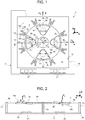
- Figure 1 shows an exemplary embodiment of a biaxial microelectromechanical gyroscope, designated by 1, according to the teachings disclosed in the aforesaid patent applications.
- the gyroscope 1 is provided in a die 2 comprising a substrate 2a made of semiconductor material (for example, silicon), and a frame 2b; the frame 2b defines inside it an open region 2c, overlying the substrate 2a, and designed to house detection structures of the gyroscope 1 (as described in detail hereinafter).
- the open region 2c has a generally square or rectangular configuration in a horizontal plane (in what follows, plane of the sensor xy), defined by a first horizontal axis x and a second horizontal axis y, fixed with respect to the die 2.
- the frame 2b has sides substantially parallel to the horizontal axes x, y.
- Contact pads 2d are arranged along a side of the frame 2b, aligned, for example, along the first horizontal axis x. In a way not illustrated, the die pads 2d make it possible to electrically contact from the outside the detection structures of the gyroscope 1.
- the die pads 2d have an axis of symmetry, in this case coinciding with the second horizontal axis y (orthogonal to their direction of alignment), being arranged in equal number and in a specular way on opposite sides of the second horizontal axis y.
- first and second horizontal axes x, y correspond to a first axis of detection and a second axis of detection of the gyroscope 1 (more precisely, to a pitch axis and to a roll axis), about which corresponding angular velocities ⁇ x (pitch angular velocity) and ⁇ y (roll angular velocity) are detected.
- the gyroscope 1 comprises a driving structure, housed within the open region 2c and formed by a driving mass 3 and by a driving assembly 4.
- the driving mass 3 has a generally circular geometry with radial symmetry, having a substantially planar configuration with main extension in the plane of the sensor xy, and negligible dimension, with respect to the main extension, in a direction parallel to a vertical axis z, forming with the first and second horizontal axes x, y a set of three orthogonal axes, fixed with respect to the die 2.
- the driving mass 3 has in the plane of the sensor xy basically the shape of an annulus, and defines at the center an empty space 6, the center O of which coincides with the center of gravity and the center of symmetry of the entire structure.
- the driving mass 3 is anchored to the substrate 2a by means of a first anchorage 7a placed at the center O, to which it is connected through first elastic anchorage elements 8a.
- the first elastic anchorage elements 8a extend, forming a cross, from the center O parallel to the first and second horizontal axes x, y.
- the driving mass 3 is anchored to the substrate 2a by means of further anchorages 7b, set on the outside of the same driving mass 3, to which it is connected by means of further elastic anchorage elements 8b.
- the further elastic anchorage elements 8b are of the folded type, are four in number, and are aligned in pairs along the first and second horizontal axes x, y, in such a way that the further anchorages 7b are set, in pairs, on opposite sides of the driving mass 3 with respect to the empty space 6, at the vertex of a cross centered in the center O.
- the first and further elastic anchorage elements 8a, 8b enable a rotary movement of the driving mass 3 about a driving axis passing through the center O, parallel to the vertical axis z and perpendicular to the plane of the sensor xy.
- the driving mass 3 has: a first pair of through openings 9a, 9b, aligned in a diametric direction along the first horizontal axis x (pitch axis), and set on opposite sides with respect to the empty space 6; and a second pair of through openings 9c, 9d, aligned in a diametric direction along the second horizontal axis y (roll axis), and set on opposite sides with respect to the empty space 6.
- each through opening 9a-9d has in the plane of the sensor xy the shape of a radial annulus sector, having arc-shaped internal and external sides and radially extending lateral sides.
- the through openings 9a-9b of the first pair are symmetrical with respect to the second horizontal axis y
- the through openings 9c-9d of the second pair are symmetrical with respect to the first horizontal axis x.
- the driving assembly 4 comprises a plurality of driven arms 10, extending externally from the driving mass 3 in a radial direction and in such a way that they are set at equal angular distances apart from one another, and a plurality of first and second driving arms 12a, 12b, extending parallel to, and on opposite sides of, respective driven arms 10.
- Each driven arm 10 carries a plurality of first electrodes 13, extending perpendicular to, and on both sides of, the same driven arm.
- each of the first and second driving arms 12a, 12b carries respective second electrodes 14a, 14b, which extend towards the respective driven arm 10, and are combfingered with the corresponding first electrodes 13.
- the first driving arms 12a are set all on one and the same side of the respective driven arms 10, and are biased all at one and the same first potential.
- the second driving arms 12b are set all on the opposite side of the respective driven arms 10, and are biased all at one and the same second potential.
- a driving circuit (not illustrated) is connected to the second electrodes 14a, 14b for applying the first and second potentials and determining, by means of the mutual and alternating attraction of the electrodes, an oscillatory rotary motion of the driving mass 3 about the driving axis, at a given frequency of oscillation.
- the gyroscope 1 further comprises a first pair of acceleration sensors with axis parallel to the vertical axis z, and in particular a first pair of sensing masses 16a, 16b, set within a respective through opening 9a, 9b so as to be completely enclosed and contained in the overall dimensions of the driving mass 3 in the plane of the sensor xy.
- Each of the sensing masses 16a, 16b has a shape corresponding to that of the respective through opening, and consequently has, in plan view, the general shape of a radial annulus sector.
- each of the sensing masses 16a, 16b has a first portion 17, which is wider, and a second portion 18, which is narrower (along the first horizontal axis x) but has in any case dimensions comparable with those of the first portion 17, the two portions being connected by a connecting portion 19, which is shorter (in a direction parallel to the second horizontal axis y) than the first and second portions 17, 18, and consequently has a center of gravity G located within the corresponding first portion 17.
- the first portion 17 has an outer side that is arc-shaped and concave and lateral sides extending radially
- the second portion 18 has an outer side that is arc-shaped and convex and lateral sides extending radially, aligned along the lateral sides of the first portion 17.
- Each of the sensing masses 16a, 16b is supported by a pair of elastic supporting elements 20 extending from the connecting portion 19 to the driving mass 3, connecting thereto, parallel to the second horizontal axis y (the elastic supporting elements 20 extending consequently in an intermediate position with respect to the width of the respective sensing mass).
- the elastic supporting elements 20 extend within recesses 21 provided on opposite sides of the corresponding sensing mass 16a, 16b, at a distance b C from its center of gravity G.
- the gyroscope 1 further comprises a second pair of acceleration sensors with axis parallel to the vertical axis z, and in particular a second pair of sensing masses 16c, 16d, housed within the through openings 9c, 9d, and completely enclosed and contained by the driving mass 3.
- the sensing masses 16c, 16d are obtained from the rotation through 90° of the sensing masses 16a, 16b with respect to the center O, and consequently the corresponding elastic supporting elements 20 extend parallel to the first horizontal axis x and enable rotation out of the plane of the sensor xy, about an axis of rotation parallel to the first horizontal axis x.
- a pair of first and second sensing electrodes 22, 23 is set underneath the first and second portions 17, 18 of each of the sensing masses 16a-16d.
- the first and second sensing electrodes 22, 23 are polycrystalline-silicon regions formed on top of the substrate 2a and having a substantially trapezoidal shape and dimensions substantially the same as one another and corresponding to those of the second portion 18.
- the first and second sensing electrodes 22, 23 are separated, respectively, from the first and second portions 17, 18, by an air gap, and form, together with the first and second portions 17, 18 respective sensing capacitors.
- the first and second sensing electrodes 22, 23 of each sensing mass 16a-16d are connected in a differential way to a read circuit of the gyroscope 1 (not illustrated) via the connection pads 2d.
- the gyroscope 1 is able to operate as a biaxial gyroscope, and to detect a (pitch) angular velocity ⁇ x about the first horizontal axis x, and a (roll) angular velocity ⁇ y about the second horizontal axis y.
- the rotary movement of the driving mass 3 and of the sensing masses 16a-16d about the driving axis can be represented by a driving-velocity vector v a , tangential to the circumference that describes the path thereof.
- the rotary motion about the first horizontal axis x or the second horizontal axis y with angular velocity ⁇ x , ⁇ y causes a Coriolis force (designated by F C ) acting on the entire structure, proportional to the vector product between the angular velocity ⁇ x , ⁇ y and the driving velocity v a , and hence directed along the vertical axis z.
- the configuration of the first and further elastic anchorage elements 8a, 8b is such as to inhibit, to a good approximation, the movement of the driving mass 3 out of the plane of the sensor xy, in this way enabling the effective decoupling of the motion of detection of the sensing masses with respect to the driving motion.
- Displacement of the sensing masses 16a-16d out of the plane of the sensor xy causes the approach/moving away of the first portion 17 to/from the respective sensing electrode 22, and a corresponding moving away/approach of the second portion 18 from/to the respective sensing electrode 23.
- the presence of a pair of electrodes 22, 23 for each of the sensing masses 16a-16d enables automatic rejection of linear spurious accelerations along the vertical axis z.
- a rotation about the first horizontal axis x is not felt by the second pair of sensing masses 16c, 16d, in so far as the resultant Coriolis force F C is zero (since the vector product between the angular velocity ⁇ x and the corresponding driving velocity v a goes to zero).
- the rotation about the second horizontal axis y is not felt for similar reasons by the first pair of sensing masses 16a, 16b, so that the two axes of detection are not affected and are substantially decoupled.
- the particular conformation of the sensing masses 16a-16d enables increase in the sensitivity of the gyroscope 1 (as compared to the use of other geometries for the same first sensing masses).
- the corresponding center of gravity G is positioned at a distance b C from the elastic supporting elements 20 (and from the corresponding axis of rotation out of the plane of the sensor xy) that is greater than that of the center of gravity of any rectangular mass that can be inscribed in one and the same sector of the driving mass 3 and is supported by elastic supporting elements extending along the same axis of rotation. Consequently, it is possible to obtain a higher torque and hence a greater movement of rotation out of the plane of the sensor xy, and in this way to obtain a higher sensor sensitivity.
- the presence of the further elastic anchorage elements 8b, located outside the driving mass 3, enables increase of the stiffness of the driving mass 3 in regard to the movements out of the plane of the sensor xy, and hence increase of the decoupling between the driving movement and the detection movements.
- US 2006/1127 64 A1 discloses an angular velocity detector having an inertial mass which is made to oscillate in a rotational direction; a detection mass is connected to the inertial mass via detecting beams, so as to displace in a vertical direction due to an angular velocity to be detected, independently from the driving movement of the inertial mass.
- US 2002/0189352 A1 discloses a MEMS sensor including a drive ring, oscillating about a drive axis, and a sense plate elastically coupled to the drive ring and to a central anchor, via connection elements allowing a single-degree-of-freedom rocking motion about a sense axis.
- US 2008/0276706 A1 discloses a rotational rate sensor including sensing masses, each sensing mass suspended in cantilever fashion above a substrate, by means of suspension elements, coupled to an end portion thereof.
- the aim of the present invention is consequently to further improve the structure of the microelectromechanical gyroscope, in particular as regards its sensitivity to angular velocities.
- microelectromechanical structure as defined in claim 1, is provided according to the present invention.
- an aspect of the present invention envisages providing a microelectromechanical gyroscope having a structural configuration such as to enable an increase in the sensitivity of the sensor and in general an improvement of its electrical characteristics.
- the microelectromechanical gyroscope here designated by 30, differs from the gyroscope 1 of Figure 1 substantially on account of a different arrangement of the sensing masses, here designated by 16a'-16b', of the corresponding elastic supporting elements, here designated by 20', and of the sensing electrodes.
- Figure 3 for simplicity of illustration, regards the case of a uniaxial gyroscope, capable of detecting pitch angular velocities ⁇ x about the first horizontal axis x.
- the elastic supporting elements 20' are positioned at an end portion 31 of the corresponding sensing mass 16a'-16b', in particular the end portion having a smaller internal radius, i.e. being radially more internal, with respect to the center O (or, equivalently, having a smaller extension along the second horizontal axis y), instead of extending in an intermediate position with respect to the sensing mass 16a'-16b'.
- the elastic supporting elements 20' extend externally with respect to the respective sensing mass 16a'-16b', on opposite sides thereof, towards internal sides of the respective opening 9a'-9b' (which in this case has dimensions sufficiently greater than those of the corresponding sensing mass, for accommodating the same elastic supporting elements).
- the axis of rotation defined by the elastic supporting elements 20' extends, within the respective sensing mass, only through the aforesaid end portion 31.
- Each sensing mass 16a'-16b' hence extends in cantilever fashion above the substrate 2a, starting from the corresponding elastic supporting elements 20', and extends substantially throughout its width (with respect to the first horizontal axis x), on just one side of the same elastic supporting elements 20'.
- the sensing masses 16a'-16b' are hence constituted by a single main body (or bulk), here designated by 17', which is continuous and not interrupted internally by the elastic supporting elements 20', and extends on just one side of the same elastic supporting elements 20'.
- a single sensing electrode here designated by 32, is associated to each sensing mass 16a'-16b'; the sensing electrode 32 extends underneath the corresponding sensing mass, and has dimensions and an extension substantially corresponding to those of the same sensing mass (in particular to its bulk 17').
- the sensing electrode 32 has a substantially trapezoidal geometry in plan view.
- the sensing masses 16a'-16b' are arranged in a symmetrical way with respect to the second horizontal axis y so that the corresponding center of gravity G' is positioned on opposite sides of the corresponding elastic supporting elements 20' with respect to the first horizontal axis x.
- the Coriolis force F C deriving from the application of the pitch angular velocity ⁇ x causes rotation of the sensing masses 16a'-16b' about the respective elastic supporting elements 20' (reference may once again be made, by analogy, to Figure 2 ), operating in such a way that one sensing mass 16a' moves away from the respective sensing electrode 32, and the other sensing mass 16b' undergoes a corresponding approach to the respective sensing electrode 32.
- the present applicant has realized that, with an appropriate sizing of the elastic supporting elements 20', it is possible to leave the natural frequency of the sensing masses 16a'-16b' unvaried. Given the same natural frequency, the arrangement in cantilever fashion of the sensing masses 16a'-16b' considerably increases the distance of the center of gravity G' from the axis of rotation and the arm b C ' of the Coriolis force F C (as compared to a traditional solution, with the elastic supporting elements in an intermediate position with respect to the same sensing masses), and hence displacement of the sensing masses 16a'-16b' due to application of the angular velocity ⁇ x . Consequently, a considerable increase in the sensitivity of the gyroscope 30 in the detection of the angular velocities is obtained.
- the single sensing electrode 32 can have an area greater than the sum of the areas of the two sensing electrodes 22, 23, provided, in differential configuration, in the traditional solution of Figure 1 , guaranteeing a further increase in sensitivity (given that the value of the capacitance of the sensing capacitor is evidently proportional to the surface of the electrodes).
- the differential detection scheme makes it once again possible to guarantee the possibility of rejecting undesirable accelerations.
- the present applicant has realized that the use of a single sensing electrode 32 associated to each sensing mass 16a'-16b' may have a drawback in that the pair of sensing masses are no longer completely insensitive to the acceleration of gravity. This implies that the sensitivity of the gyroscope 30 does not remain exactly constant, if the gyroscope 30 is kept upright or turned upside down with respect to a horizontal plane (the plane of the sensor xy).
- the force of gravity causes a same approach of the two sensing masses 16a'-16b' towards the respective sensing electrode 32, with a decrease in the average gap of both of the sensing capacitors.
- This entails an equal increase of capacitance of both of the sensing capacitors and consequently an increase of sensitivity of the gyroscope 30.
- the average gap between the sensing electrodes 32 and the corresponding sensing mass 16a'-16b' increases, and the sensitivity of detection decreases.
- the present applicant has also verified that an adequate sizing of the sensing masses 16a'-16b', for example, in terms of geometry and natural frequency thereof, makes it possible to keep the sensitivity variation due to the presence of gravity within widely acceptable values (for example, equal to 1% or 2%), which does not imply problems for proper operation of the gyroscope 30.
- Figure 4 shows a gyroscope 30 of a biaxial type, capable of detecting pitch angular velocities ⁇ x about the first horizontal axis x, and also roll angular velocities ⁇ y about the second horizontal axis y.
- the gyroscope 30 further comprises the second pair of sensing masses 16c'-16d', aligned along the second horizontal axis y.
- each of the sensing masses 16c'-16d' of the second pair extends in cantilever fashion from the respective elastic supporting elements 20', which are arranged at an end portion 31 thereof (once again the end portion with smaller radius and with smaller extension along the first horizontal axis x).
- a further aspect of the present invention envisages a different arrangement of the sensing masses 16a'-16d', aimed at obtaining a further increase in the sensitivity of detection of the angular velocities and in general in the efficiency of the gyroscope 30.
- the sensing masses 16a', 16b' of the first pair are in this case aligned in a first diametric direction x 1 , inclined with respect to the first horizontal axis x of the die 2 by an inclination angle ⁇ (considered in a counterclockwise direction), the value of which is preferably 45° (but which, for specific design requirements, can be, for example, comprised between 40° and 50°).
- the sensing masses 16c', 16d' of the second pair are aligned in a second diametric direction x 2 , substantially orthogonal to the first diametric direction x 1 , and inclined with respect to the first horizontal axis x by the same angle of inclination ⁇ (considered in this case in an opposite direction, namely clockwise).
- the sensing masses 16a'-16d' are consequently aligned in respective diametric directions, which are inclined with respect to the pitch and roll axes, applied about which are the pitch angular velocity ⁇ x and the roll angular velocity ⁇ y , and also inclined with respect to the sides of the die 2 (and to the horizontal axes x, y).
- each of the sensing masses 16a', 16b' of the first pair is symmetrical to a corresponding sensing mass 16d', 16c' of the second pair, with respect to the axis of symmetry of the die pads 2d (coinciding with the second horizontal axis y).
- the present applicant has found that the aforesaid arrangement of the sensing masses 16a'-16d' enables a series of advantages to be obtained, amongst which a simplified connection of the corresponding sensing electrodes 32 towards the die pads 2d.
- a first processing channel in the electronic read interface and corresponding electrical connections to the connection pads 2d are associated to the first pair of sensing masses 16a'-16b', whilst to the second pair of sensing masses 16c'-16d' are associated a second distinct processing channel in the same electronic read interface and corresponding electrical connections to the respective connection pads 2d.
- connection pads 2d The present applicant has found that the arrangement described in Figure 5 for the sensing masses 16a'-16d' with respect to the connection pads 2d enables a substantial symmetry of the electrical connections to said connection pads 2d to be obtained for the two processing channels (the two pairs of sensing masses are in fact arranged in an altogether symmetrical way with respect to the axis of symmetry of the connection pads 2d).
- the symmetry of the electrical connections enables, as it is known, considerable advantages to be obtained in terms of uniformity in the electrical characteristics (for example, in terms of active and parasitic capacitances, or leakage currents) and robustness to the parameter spread resulting from the manufacturing process.
- the aforesaid arrangement of the sensing masses 16a'-16d' makes it possible to optimize exploitation of the space available in the gyroscope for detection of the angular velocities.
- the area available for providing the detection structures, coinciding with the open region 2c defined by the frame 2b of the die 2, usually has a square shape (as is shown in Figures 3-5 ) or a rectangular shape.
- the arrangement of the sensing masses 16a'-16d' in directions inclined with respect to the sides of the frame 2b and to the horizontal axes x, y enables (in a way not illustrated) increase in the dimensions and maximization of the sensitivity of the sensing masses, exploiting for detection the areas at a greater distance from the driving axis of rotation.
- the aforesaid arrangement of the sensing masses 16a'-16d' makes it possible to obtain, using an appropriate configuration of the electronic read interface, a further increase in the sensitivity of the gyroscope 30.
- the gyroscope 30 shown in Figure 5 has the peculiarity of having the axes of detection in the plane of the sensor xy (coinciding with the first and second diametric directions x 1 , x 2 of alignment of the sensing masses 16a'-16d') inclined by the angle ⁇ with respect to the horizontal axes x and y about which the pitch angular velocity ⁇ x and the roll angular velocity ⁇ y act.
- a further aspect of the present invention envisages to suitably combine, at the electronic read interface level, the detection signals coming from the sensing masses 16a'-16d'.
- the detection signals are combined so as to re-obtain, starting from the capacitive variations associated to the displacements of the first sensing masses 16a'-16d', voltage outputs corresponding to the original pitch and roll directions (i.e. to the horizontal axes x and y).
- Figure 6 illustrates an electronic device 40 comprising the microelectromechanical gyroscope 30 described previously.
- the electronic device 40 can advantageously be used in a plurality of electronic systems, for example, in inertial navigation systems, in automotive systems or in systems of a portable type, such as, for example: a PDA (Personal Digital Assistant); a portable computer; a cellphone; a digital audio player; a photographic camera or a camcorder; or further systems capable of processing, storing, transmitting and receiving signals and information.
- a PDA Personal Digital Assistant
- portable computer a cellphone; a digital audio player; a photographic camera or a camcorder; or further systems capable of processing, storing, transmitting and receiving signals and information.
- the electronic device 40 further comprises: a driving circuit 41, operatively coupled to the driving assembly 4 for imparting the driving movement on the driving mass 3, and supplying biasing signals to the microelectromechanical structures (in a per-se known manner, which is not illustrated in detail herein); a read circuit 42, operatively coupled to the sensing electrodes 22, 23 of the first and second sensing masses, for detecting the amount of displacement of the same sensing masses and determining the angular velocities acting on the structure; and an electronic control unit 44, connected to the read circuit 42, and designed to supervise general operation of the electronic device 40, for example, on the basis of the angular velocities detected and determined.
- the read circuit 42 includes the aforesaid electronic read interface, designed to suitably combine the output signals corresponding to the individual first sensing masses, in order to increase the sensitivity of detection, as previously described.
- the arrangement of the sensing masses, suspended in cantilever fashion from the respective elastic supporting elements enables a considerable increase of the arm of the Coriolis force and the value of the resultant torque, in such a way as to enable a considerable increase of sensitivity in detection of angular velocities.
- this arrangement enables positioning, underneath each sensing mass, of a single sensing electrode, of greater dimensions as compared to traditional solutions, a fact that enables a further increase in the sensitivity of the gyroscope 30.
- a single sensing electrode renders the sensitivity gravity-dependent, it has been shown that an appropriate sizing of the structure makes it possible to maintain the resulting variation of sensitivity within substantially negligible values. Possibly, said variations can also be appropriately compensated for by the read electronics associated to the gyroscope 30.
- the arrangement of the sensing masses in directions of alignment inclined with respect to the horizontal axes makes it possible to optimize exploitation of the area available for detection, further increase the sensitivity of the sensor, and improve uniformity of the electrical characteristics and robustness of the system to disturbance.
- the elastic supporting elements 20' can be set within, instead of extending outside, the sensing masses.
- different geometries can be provided for the sensing masses 16a'-16d', for example, a rectangular geometry, a trapezoidal geometry, or a generally rhomboidal geometry.
- the elastic supporting elements 20' extend in this case in recesses 21 obtained within the sensing mass in an area corresponding to the end portion 31 thereof (in particular, the end that is radially more internal with respect to the center O).
- the elastic supporting elements 20' (and the recesses 21) divide the sensing mass 16a' into a bulk 17' (having substantially the same overall dimensions of the sensing mass) and a portion of dimensions altogether negligible with respect to the bulk 17'.
- the elastic supporting elements 20' extend at the opposite end of the sensing mass 16a', i.e., in an area corresponding to the end portion (here designated by 31') radially more external with respect to the center O, or, in the specific case of a sensing mass having a trapezoidal conformation (as shown in the same Figure 8 ), having a greater extension along the second horizontal axis y.
- Figure 9 shows a further geometrical variant of the sensing mass 16a', having a generally rhomboidal conformation (with the elastic supporting elements 20' extending externally with respect to the sensing mass, in an area corresponding to the end portion 31 that is radially more internal with respect to the center O).
- the configuration described of the sensing masses can advantageously be provided also for a triaxial gyroscope, i.e., one that is sensitive also to yaw angular velocities (and provided for this purpose with two further sensing masses sensitive to Coriolis forces acting in the plane of the sensor xy - see the aforesaid patent applications for further details).
- microelectromechanical structure in its simplest embodiment, can possibly comprise just one sensing mass, with the disadvantage of not being able to reject linear accelerations in the direction of detection.
- the displacement of the sensing masses can be determined with a technique different from the capacitive one, for example, by detection of a magnetic force.
- the torque for causing oscillation of the driving mass with rotary movement can be generated in a different way, for example, by means of parallel-plate electrodes, or else by magnetic actuation.
- the driving motion may even not be rotary, but of a translational type.
- the configuration of some structural elements of the gyroscope 30 can be different.
- the driving mass 3 can have a shape different from the circular one, for example, a generally closed polygonal shape, as likewise the shape of the frame 2b of the die 2 can be different.
- different conformations and dimensions of the sensing electrodes associated to the sensing masses may be envisaged.
Claims (12)
- Integrierte mikroelektromechanische Struktur (30), umfassend:ein Die, (2) der ein Substrat (2a) und einen Rahmen (2b) aufweist, der in seinem Inneren einen Sensorbereich (2c) definiert und eine erste Seite, die sich parallel zu einer ersten horizontalen Achse (x) erstreckt, und eine zweite Seite, die sich parallel zu einer zweiten horizontalen Achse (y) erstreckt, aufweist;elastische Verankerungselemente (8a, 8b);eine Antriebsmasse (3), die über die elastischen Verankerungselemente (8a, 8b) an dem Substrat (2a) verankert ist und gestaltet ist, mit einer Antriebsbewegung in einer Ebene (xy) drehbar bewegt zu werden;eine erste Sensormasse (16a');elastische Stützelemente (20');wobei die erste Sensormasse (16a') über die elastischen Stützelemente (20') innerhalb der Antriebsmasse (3) aufgehängt ist und mit ihr gekoppelt ist, um in Bezug auf die Antriebsmasse (3) in der Antriebsbewegung fixiert zu sein und eine Detektionsbewegung der Drehung aus der Ebene (xy) heraus durchzuführen, in Reaktion auf eine erste Winkelgeschwindigkeit
Ω X ;wobei die elastischen Stützelemente (20') mit der ersten Sensormasse (16a') an einem Endabschnitt (31; 31') der ersten Sensormasse gekoppelt sind und konfiguriert sind, eine Torsion erfahren, um die Detektionsbewegung zu ermöglichen, und eine Drehachse der Detektionsbewegung sich innerhalb der ersten Sensormasse (16a') nur durch den Endabschnitt (31; 31') hindurch erstreckt und durch die elastischen Stützelemente (20') verläuft,umfassend eine weitere Sensormasse (16b'), die innerhalb der Antriebsmasse (3) aufgehängt ist und über jeweilige weitere elastische Stützelemente (20') mit ihr gekoppelt ist, mit der ersten Sensormasse (16a') operativ gekoppelt und mit ihr ein erstes Paar von Sensormassen (16a', 16b') bildend, die in einer ersten Richtung (x1) der Ebene (xy) ausgerichtet sind;wobei ein jeweiliger Endabschnitt (31; 31') der Sensormassen (16a, 16b') in einem Bereich angeordnet ist, der in Bezug auf einen Drehmittelpunkt (O) der Antriebsmasse (3) einer radial weiter innenliegenden Seite der Sensormassen (16a', 16b') entspricht;wobei die elastischen Stützelemente (20') die Drehachse der Detektionsbewegung definieren; und die Sensormassen (16a', 16b') des ersten Paares sich freitragend von den jeweiligen elastischen Stützelementen (20') erstrecken, eine (16a') auf der Seite gegenüber der anderen (16b') in Bezug auf die elastischen Stützelemente (20') entlang der ersten Richtung (x1);wobei die Struktur vom biaxialen Typ ist, ferner umfassend ein zweites Paar von Sensormassen (16c', 16d'), die innerhalb der Antriebsmasse (3) aufgehängt und mit ihr über jeweilige weitere elastische Stützelemente (20') gekoppelt sind, und in einer zweiten Richtung (x2) ausgerichtet sind; wobei die jeweiligen weiteren elastischen Stützelemente (20') mit einem jeweiligen Endabschnitt (31; 31') der Sensormassen (16c', 16d') des zweiten Paares gekoppelt sind, so dass sich die Drehachse einer jeweiligen Detektionsbewegung innerhalb der Sensormassen (16c', 16d') des zweiten Paares nur durch den jeweiligen Endabschnitt (31; 31') hindurch erstreckt; wobei die erste Richtung (x1) und die zweite Richtung (x2) eine von Null verschiedene Neigung mit entgegengesetztem Vorzeichen in Bezug auf die erste horizontale Achse (x) aufweisen, so dass das erste und das zweite Paar von Sensormassen konfiguriert sind, Detektionsbewegungen von Drehungen aus der Ebene (xy) heraus durchzuführen, in Reaktion auf eine erste und eine zweite Winkelgeschwindigkeit (Ω X , Ω Y ) um die erste und die zweite horizontale Achse (x, y). - Struktur nach Anspruch 1, wobei die Antriebsbewegung eine Drehung um eine vertikale Achse (z) senkrecht zu der Ebene (xy) ist, und wobei die Antriebsmasse (3) in ihrem Innern mindestens eine Durchgangsöffnung (9a', 9b') aufweist; und wobei die erste Sensormasse (16a') in der Durchgangsöffnung (9a', 9b') angeordnet ist, und die elastischen Stützelemente (20') sich innerhalb der Durchgangsöffnung (9a', 9b') zwischen der Antriebsmasse (3) und dem Endabschnitt (31; 31') erstrecken; wobei die elastischen Verankerungselemente (8a, 8b) und die elastischen Stützelemente (20') so konfiguriert sind, dass die Antriebsmasse (3) während der Detektionsbewegung von der ersten Sensormasse (16a') entkoppelt ist.
- Struktur nach Anspruch 1 oder 2, wobei der ersten Sensormasse (16a') eine einzelne Sensorelektrode (32) zugeordnet ist, die einen Sensorkondensator mit der ersten Sensormasse bildet; wobei die Sensorelektrode (32) auf dem Substrat (2) und unterhalb der ersten Sensormasse (16a') angeordnet ist.
- Struktur nach Anspruch 3, wobei sich die erste Sensormasse (16a') freitragend von den elastischen Stützelementen (20') erstreckt und einen Hauptkörper (17') aufweist, der ausschließlich auf nur einer Seite der Drehachse angeordnet ist; und wobei die Sensorelektrode (32) unterhalb des Hauptkörpers (17') ist.
- Struktur nach Anspruch 4, wobei die Sensorelektrode (32) Abmessungen aufweist, die im Wesentlichen mit den Abmessungen des Hauptkörpers (17') übereinstimmen.
- Struktur nach Anspruch 1, wobei die erste Richtung (x1) in Bezug auf die erste horizontale Achse (x) um einen Winkel (α) geneigt ist, und die zweite Richtung (x2) in Bezug auf die erste horizontale Achse auf der gegenüberliegenden Seite um denselben Winkel (α) geneigt ist.
- Struktur nach Anspruch 6, wobei der Winkel (α) einen Wert von im Wesentlichen gleich 45° aufweist und die erste Richtung (x1) und die zweite Richtung (x2) im Wesentlichen orthogonal zueinander sind.
- Struktur nach einem der vorhergehenden Ansprüche, ferner umfassend mehrere Die-Kontaktstellen (2d), die sich entlang der ersten Seite des Rahmens (2b) in einer in Bezug auf eine zweite horizontale Achse (y) symmetrischen Weise erstrecken; wobei jede der Sensormassen des ersten Paars (16a', 16b') zu einer entsprechenden der Sensormassen des zweiten Paars (16d', 16c') in Bezug auf die zweite horizontale Achse (y) symmetrisch angeordnet ist.
- Struktur nach einem der vorhergehenden Ansprüche, wobei bei Verwendung die erste Winkelgeschwindigkeit (
Ω X ) um die erste horizontale Achse (x) herum, die mit einer ersten Detektionsachse der Struktur (30) übereinstimmt, angewandt wird. - Struktur nach einem der vorhergehenden Ansprüche, wobei die Antriebsmasse (3) in der Mitte einen leeren Raum (6) definiert und an dem Substrat (2) verankert ist, an einer ersten Verankerung (7a), die im Wesentlichen in der Mitte (O) des leeren Raums (6) angeordnet ist, über erste elastische Verankerungselemente (8a), die sich innerhalb des leeren Raums (6) erstrecken, und auch an weiteren Verankerungen (7b), die an der Außenseite der Antriebsmasse (3) angeordnet sind, über weitere elastische Verankerungselemente (8b);
wobei die elastischen Stützelemente (6) und das erste (8a) und die weiteren (8b) Verankerungselemente so konfiguriert sind, dass die Antriebsmasse (3) bei der Detektionsbewegung der Drehung aus der Ebene (xy) heraus von der ersten Sensormasse (16a') entkoppelt ist. - Struktur nach einem der vorhergehenden Ansprüche, wobei die erste Sensormasse (16a') eine Form aufweist, die einen Schwerpunkt (G') aufweist, der sich in einem Abstand (bc') von der Drehachse der Detektionsbewegung befindet, der größer ist als der des Schwerpunkts einer Sensormasse, die eine rechteckige Form aufweist, die in ein und denselben Sektor der Antriebsmasse (3) einbeschrieben sein kann und durch jeweilige elastische Stützelemente zur Drehung um die Drehachse getragen wird.
- Elektronische Vorrichtung (40), umfassend eine integrierte mikroelektromechanische Struktur (30) nach einem der vorhergehenden Ansprüche, und eine Lesestufe (42), die mit der integrierten mikroelektromechanischen Struktur (30) operativ gekoppelt ist.
Applications Claiming Priority (1)
| Application Number | Priority Date | Filing Date | Title |
|---|---|---|---|
| ITTO2008A000877A IT1391973B1 (it) | 2008-11-26 | 2008-11-26 | Giroscopio microelettromeccanico mono o biassiale con aumentata sensibilita' al rilevamento di velocita' angolari |
Publications (2)
| Publication Number | Publication Date |
|---|---|
| EP2192383A1 EP2192383A1 (de) | 2010-06-02 |
| EP2192383B1 true EP2192383B1 (de) | 2018-10-03 |
Family
ID=41170926
Family Applications (1)
| Application Number | Title | Priority Date | Filing Date |
|---|---|---|---|
| EP09177122.0A Active EP2192383B1 (de) | 2008-11-26 | 2009-11-25 | Einachsiges oder zweiachsiges mikroelektromechanisches Gyroskop mit verbesserter Empfindlichkeit der Winkelgeschwindigkeitsdetektion |
Country Status (3)
| Country | Link |
|---|---|
| US (2) | US8312769B2 (de) |
| EP (1) | EP2192383B1 (de) |
| IT (1) | IT1391973B1 (de) |
Families Citing this family (29)
| Publication number | Priority date | Publication date | Assignee | Title |
|---|---|---|---|---|
| US8042394B2 (en) * | 2007-09-11 | 2011-10-25 | Stmicroelectronics S.R.L. | High sensitivity microelectromechanical sensor with rotary driving motion |
| WO2009087858A1 (ja) * | 2008-01-07 | 2009-07-16 | Murata Manufacturing Co., Ltd. | 角速度センサ |
| IT1391972B1 (it) | 2008-11-26 | 2012-02-02 | St Microelectronics Rousset | Giroscopio microelettromeccanico con movimento di azionamento rotatorio e migliorate caratteristiche elettriche |
| IT1391973B1 (it) * | 2008-11-26 | 2012-02-02 | St Microelectronics Rousset | Giroscopio microelettromeccanico mono o biassiale con aumentata sensibilita' al rilevamento di velocita' angolari |
| ITTO20090489A1 (it) | 2008-11-26 | 2010-12-27 | St Microelectronics Srl | Circuito di lettura per un giroscopio mems multi-asse avente direzioni di rilevamento inclinate rispetto agli assi di riferimento, e corrispondente giroscopio mems multi-asse |
| IT1392741B1 (it) | 2008-12-23 | 2012-03-16 | St Microelectronics Rousset | Giroscopio microelettromeccanico con migliorata reiezione di disturbi di accelerazione |
| IT1394007B1 (it) | 2009-05-11 | 2012-05-17 | St Microelectronics Rousset | Struttura microelettromeccanica con reiezione migliorata di disturbi di accelerazione |
| US8534127B2 (en) | 2009-09-11 | 2013-09-17 | Invensense, Inc. | Extension-mode angular velocity sensor |
| US9097524B2 (en) | 2009-09-11 | 2015-08-04 | Invensense, Inc. | MEMS device with improved spring system |
| ITTO20091042A1 (it) * | 2009-12-24 | 2011-06-25 | St Microelectronics Srl | Giroscopio integrato microelettromeccanico con migliorata struttura di azionamento |
| ITTO20110806A1 (it) | 2011-09-12 | 2013-03-13 | St Microelectronics Srl | Dispositivo microelettromeccanico integrante un giroscopio e un accelerometro |
| US8448513B2 (en) | 2011-10-05 | 2013-05-28 | Freescale Semiconductor, Inc. | Rotary disk gyroscope |
| US8739627B2 (en) * | 2011-10-26 | 2014-06-03 | Freescale Semiconductor, Inc. | Inertial sensor with off-axis spring system |
| DE102011057081A1 (de) * | 2011-12-28 | 2013-07-04 | Maxim Integrated Products, Inc. | Mikro-Drehratensensor und Verfahren zum Betreiben eines Mikro-Drehratensensors |
| JP6338813B2 (ja) * | 2012-04-03 | 2018-06-06 | セイコーエプソン株式会社 | ジャイロセンサー及びそれを用いた電子機器 |
| US9404747B2 (en) | 2013-10-30 | 2016-08-02 | Stmicroelectroncs S.R.L. | Microelectromechanical gyroscope with compensation of quadrature error drift |
| CN105043370B (zh) * | 2014-04-29 | 2019-01-22 | 财团法人工业技术研究院 | 具有支点元件的微型电机装置 |
| EP3034997B1 (de) * | 2014-12-18 | 2020-12-16 | RISE Research Institutes of Sweden AB | MEMS-Kreisel |
| CN205593534U (zh) * | 2015-04-24 | 2016-09-21 | 意法半导体股份有限公司 | 微机电陀螺仪和电子系统 |
| ITUA20162172A1 (it) * | 2016-03-31 | 2017-10-01 | St Microelectronics Srl | Sensore accelerometrico realizzato in tecnologia mems avente elevata accuratezza e ridotta sensibilita' nei confronti della temperatura e dell'invecchiamento |
| US10161826B2 (en) | 2016-05-04 | 2018-12-25 | International Business Machines Corporation | Method and apparatus for inducing multiaxial excitation |
| US10371521B2 (en) | 2016-05-26 | 2019-08-06 | Honeywell International Inc. | Systems and methods for a four-mass vibrating MEMS structure |
| US10696541B2 (en) | 2016-05-26 | 2020-06-30 | Honeywell International Inc. | Systems and methods for bias suppression in a non-degenerate MEMS sensor |
| DE102017213637A1 (de) * | 2017-08-07 | 2019-02-07 | Robert Bosch Gmbh | Ein- und zweiachsiger Drehratensensor |
| JP6849042B2 (ja) | 2018-12-19 | 2021-03-24 | 株式会社村田製作所 | 振動に強い多軸ジャイロスコープ |
| EP3671116B1 (de) * | 2018-12-19 | 2021-11-17 | Murata Manufacturing Co., Ltd. | Synchronisiertes gyroskop mit mehreren achsen |
| CN113196009A (zh) * | 2019-01-08 | 2021-07-30 | 松下知识产权经营株式会社 | 感测设备 |
| DE102020205369A1 (de) * | 2020-04-28 | 2021-10-28 | Robert Bosch Gesellschaft mit beschränkter Haftung | Mikromechanisches Bauteil für einen Drehratensensor und entsprechendes Herstellungsverfahren |
| CN115355898A (zh) * | 2022-07-15 | 2022-11-18 | 瑞声开泰科技(武汉)有限公司 | 一种全解耦三轴mems陀螺 |
Citations (1)
| Publication number | Priority date | Publication date | Assignee | Title |
|---|---|---|---|---|
| US20080276706A1 (en) * | 2004-09-27 | 2008-11-13 | Conti Temic Microelectronic Gmbh | Rotation Speed Sensor |
Family Cites Families (54)
| Publication number | Priority date | Publication date | Assignee | Title |
|---|---|---|---|---|
| US5447068A (en) | 1994-03-31 | 1995-09-05 | Ford Motor Company | Digital capacitive accelerometer |
| DE4414237A1 (de) | 1994-04-23 | 1995-10-26 | Bosch Gmbh Robert | Mikromechanischer Schwinger eines Schwingungsgyrometers |
| DE19530007C2 (de) | 1995-08-16 | 1998-11-26 | Bosch Gmbh Robert | Drehratensensor |
| US6250156B1 (en) | 1996-05-31 | 2001-06-26 | The Regents Of The University Of California | Dual-mass micromachined vibratory rate gyroscope |
| DE19641284C1 (de) * | 1996-10-07 | 1998-05-20 | Inst Mikro Und Informationstec | Drehratensensor mit entkoppelten orthogonalen Primär- und Sekundärschwingungen |
| US6230563B1 (en) | 1998-06-09 | 2001-05-15 | Integrated Micro Instruments, Inc. | Dual-mass vibratory rate gyroscope with suppressed translational acceleration response and quadrature-error correction capability |
| DE19938206A1 (de) * | 1999-08-12 | 2001-02-15 | Bosch Gmbh Robert | Mikromechanischer Drehbeschleunigungssensor |
| DE10108196A1 (de) | 2001-02-21 | 2002-10-24 | Bosch Gmbh Robert | Drehratensensor |
| DE60120921T2 (de) | 2001-04-27 | 2007-02-01 | Stmicroelectronics S.R.L., Agrate Brianza | Aus Halbleitermaterial hergestellter integrierter Kreisel |
| US6928872B2 (en) * | 2001-04-27 | 2005-08-16 | Stmicroelectronics S.R.L. | Integrated gyroscope of semiconductor material with at least one sensitive axis in the sensor plane |
| US6535800B2 (en) | 2001-05-29 | 2003-03-18 | Delphi Technologies, Inc. | Vehicle rollover sensing using angular rate sensors |
| US20020189351A1 (en) * | 2001-06-14 | 2002-12-19 | Reeds John W. | Angular rate sensor having a sense element constrained to motion about a single axis and flexibly attached to a rotary drive mass |
| US6722197B2 (en) | 2001-06-19 | 2004-04-20 | Honeywell International Inc. | Coupled micromachined structure |
| US6513380B2 (en) * | 2001-06-19 | 2003-02-04 | Microsensors, Inc. | MEMS sensor with single central anchor and motion-limiting connection geometry |
| FI119159B (fi) | 2003-02-11 | 2008-08-15 | Vti Technologies Oy | Kapasitiivinen kiihtyvyysanturirakenne |
| US6848304B2 (en) | 2003-04-28 | 2005-02-01 | Analog Devices, Inc. | Six degree-of-freedom micro-machined multi-sensor |
| US6837107B2 (en) | 2003-04-28 | 2005-01-04 | Analog Devices, Inc. | Micro-machined multi-sensor providing 1-axis of acceleration sensing and 2-axes of angular rate sensing |
| FR2858853B1 (fr) | 2003-08-13 | 2006-01-13 | Sercel Rech Const Elect | Accelerometre a vibrations parasites reduites par forme des electrodes amelioree |
| FR2859528B1 (fr) | 2003-09-09 | 2006-01-06 | Thales Sa | Gyrometre micro-usine a double diapason et a detection dans le plan de la plaque usinee |
| JP2005241500A (ja) | 2004-02-27 | 2005-09-08 | Mitsubishi Electric Corp | 角速度センサ |
| EP1735591B1 (de) | 2004-04-14 | 2014-01-22 | Analog Devices, Inc. | Trägheitssensor mit einem linearen array von sensorelementen |
| KR100652952B1 (ko) | 2004-07-19 | 2006-12-06 | 삼성전자주식회사 | 커플링 스프링을 구비한 멤스 자이로스코프 |
| EP1624286B1 (de) | 2004-08-03 | 2017-10-04 | STMicroelectronics Srl | Mikroelektromechanischer Sensor mit Kraft-Rückkopplungsschleife |
| DE602004031938D1 (de) * | 2004-08-13 | 2011-05-05 | St Microelectronics Srl | Mikroelektromechanische Struktur, insbesondere Beschleunigungssensor, mit verbesserter Unempfindlichkeit gegenüber thermischen und mechanischen Spannungen |
| SE528404C2 (sv) | 2004-10-20 | 2006-11-07 | Imego Ab | Sensorarrangemang |
| JP4353087B2 (ja) * | 2004-12-01 | 2009-10-28 | 株式会社デンソー | 回転振動型角速度センサ |
| US7155976B2 (en) | 2005-01-05 | 2007-01-02 | Industrial Technology Research Institute | Rotation sensing apparatus and method for manufacturing the same |
| US7240552B2 (en) | 2005-06-06 | 2007-07-10 | Bei Technologies, Inc. | Torsional rate sensor with momentum balance and mode decoupling |
| JP2007071677A (ja) | 2005-09-07 | 2007-03-22 | Hitachi Ltd | コンバインドセンサとその製造方法 |
| US7454246B2 (en) | 2005-09-08 | 2008-11-18 | Massachusetts Eye & Ear Infirmary | Sensor signal alignment |
| JP4887034B2 (ja) | 2005-12-05 | 2012-02-29 | 日立オートモティブシステムズ株式会社 | 慣性センサ |
| US8113050B2 (en) | 2006-01-25 | 2012-02-14 | The Regents Of The University Of California | Robust six degree-of-freedom micromachined gyroscope with anti-phase drive scheme and method of operation of the same |
| WO2007104742A1 (de) | 2006-03-10 | 2007-09-20 | Continental Teves Ag & Co. Ohg | Drehratensensor mit kopplungsbalken |
| EP1832841B1 (de) * | 2006-03-10 | 2015-12-30 | STMicroelectronics Srl | Mikroelektromechanische integrierte Sensorstruktur mit Rotationsantriebsbewegung |
| JP4687577B2 (ja) | 2006-06-16 | 2011-05-25 | ソニー株式会社 | 慣性センサ |
| DE102006046772A1 (de) * | 2006-09-29 | 2008-04-03 | Siemens Ag | Anordnung zur Messung einer Drehrate mit einem Vibrationssensor |
| US7461552B2 (en) | 2006-10-23 | 2008-12-09 | Custom Sensors & Technologies, Inc. | Dual axis rate sensor |
| JP2008129088A (ja) | 2006-11-16 | 2008-06-05 | Eastman Kodak Co | 角速度検出システムを備えるカメラの誤差除去方法 |
| EP1962054B1 (de) | 2007-02-13 | 2011-07-20 | STMicroelectronics Srl | Mikroelektromechanisches Gyroskop mit Detektionsvorrichtung mit offenem Regelkreis und Verfahren zur Steuerung eines mikroelektromechanischen Gyroskops |
| DE102007030119A1 (de) | 2007-06-29 | 2009-01-02 | Litef Gmbh | Corioliskreisel |
| DE102007057042A1 (de) | 2007-09-10 | 2009-03-12 | Continental Teves Ag & Co. Ohg | Mikromechanischer Drehratensensor mit Kopplungsbalken und Aufhängungs-Federelementen zur Unterdrückung der Quadratur |
| US8042394B2 (en) | 2007-09-11 | 2011-10-25 | Stmicroelectronics S.R.L. | High sensitivity microelectromechanical sensor with rotary driving motion |
| DE102007054505B4 (de) | 2007-11-15 | 2016-12-22 | Robert Bosch Gmbh | Drehratensensor |
| WO2009087858A1 (ja) | 2008-01-07 | 2009-07-16 | Murata Manufacturing Co., Ltd. | 角速度センサ |
| ITTO20090489A1 (it) | 2008-11-26 | 2010-12-27 | St Microelectronics Srl | Circuito di lettura per un giroscopio mems multi-asse avente direzioni di rilevamento inclinate rispetto agli assi di riferimento, e corrispondente giroscopio mems multi-asse |
| IT1391973B1 (it) * | 2008-11-26 | 2012-02-02 | St Microelectronics Rousset | Giroscopio microelettromeccanico mono o biassiale con aumentata sensibilita' al rilevamento di velocita' angolari |
| IT1391972B1 (it) | 2008-11-26 | 2012-02-02 | St Microelectronics Rousset | Giroscopio microelettromeccanico con movimento di azionamento rotatorio e migliorate caratteristiche elettriche |
| IT1392741B1 (it) * | 2008-12-23 | 2012-03-16 | St Microelectronics Rousset | Giroscopio microelettromeccanico con migliorata reiezione di disturbi di accelerazione |
| US8256290B2 (en) | 2009-03-17 | 2012-09-04 | Minyao Mao | Tri-axis angular rate sensor |
| IT1394007B1 (it) | 2009-05-11 | 2012-05-17 | St Microelectronics Rousset | Struttura microelettromeccanica con reiezione migliorata di disturbi di accelerazione |
| IT1394898B1 (it) | 2009-06-03 | 2012-07-20 | St Microelectronics Rousset | Giroscopio microelettromeccanico con attuazione a controllo di posizione e metodo per il controllo di un giroscopio microelettromeccanico |
| US8739626B2 (en) | 2009-08-04 | 2014-06-03 | Fairchild Semiconductor Corporation | Micromachined inertial sensor devices |
| US8534127B2 (en) | 2009-09-11 | 2013-09-17 | Invensense, Inc. | Extension-mode angular velocity sensor |
| ITTO20091042A1 (it) | 2009-12-24 | 2011-06-25 | St Microelectronics Srl | Giroscopio integrato microelettromeccanico con migliorata struttura di azionamento |
-
2008
- 2008-11-26 IT ITTO2008A000877A patent/IT1391973B1/it active
-
2009
- 2009-11-25 EP EP09177122.0A patent/EP2192383B1/de active Active
- 2009-11-25 US US12/626,442 patent/US8312769B2/en active Active
-
2012
- 2012-09-13 US US13/615,353 patent/US8661897B2/en active Active
Patent Citations (1)
| Publication number | Priority date | Publication date | Assignee | Title |
|---|---|---|---|---|
| US20080276706A1 (en) * | 2004-09-27 | 2008-11-13 | Conti Temic Microelectronic Gmbh | Rotation Speed Sensor |
Also Published As
| Publication number | Publication date |
|---|---|
| IT1391973B1 (it) | 2012-02-02 |
| EP2192383A1 (de) | 2010-06-02 |
| ITTO20080877A1 (it) | 2010-05-27 |
| US20100126272A1 (en) | 2010-05-27 |
| US20130061672A1 (en) | 2013-03-14 |
| US8661897B2 (en) | 2014-03-04 |
| US8312769B2 (en) | 2012-11-20 |
Similar Documents
| Publication | Publication Date | Title |
|---|---|---|
| EP2192383B1 (de) | Einachsiges oder zweiachsiges mikroelektromechanisches Gyroskop mit verbesserter Empfindlichkeit der Winkelgeschwindigkeitsdetektion | |
| EP2192382B1 (de) | Mikroelektromechanisches Gyroskop mit Rotationsantriebsbewegung und verbesserten elektrischen Eigenschaften | |
| USRE45792E1 (en) | High sensitivity microelectromechanical sensor with driving motion | |
| US7694563B2 (en) | Microelectromechanical integrated sensor structure with rotary driving motion | |
| US9278847B2 (en) | Microelectromechanical gyroscope with enhanced rejection of acceleration noises | |
| US6837107B2 (en) | Micro-machined multi-sensor providing 1-axis of acceleration sensing and 2-axes of angular rate sensing | |
| US7213458B2 (en) | Quadrature reduction in MEMS gyro devices using quad steering voltages | |
| CN105531564B (zh) | 改进的陀螺仪结构和陀螺仪 | |
| WO2007061963A2 (en) | Method of making an x-y axis dual-mass tuning fork gyroscope with vertically integrated electronics and wafer-scale hermetic packaging | |
| US20070163346A1 (en) | Frequency shifting of rotational harmonics in mems devices | |
| WO2015013827A1 (en) | Mems motion sensor for sub-resonance angular rate sensing | |
| US20130239679A1 (en) | Three-axis gyroscope | |
| US11226202B2 (en) | Three-axis micromechanical rotation rate sensor system including linearly and rotatorily drivable sensor units |
Legal Events
| Date | Code | Title | Description |
|---|---|---|---|
| PUAI | Public reference made under article 153(3) epc to a published international application that has entered the european phase |
Free format text: ORIGINAL CODE: 0009012 |
|
| AK | Designated contracting states |
Kind code of ref document: A1 Designated state(s): AT BE BG CH CY CZ DE DK EE ES FI FR GB GR HR HU IE IS IT LI LT LU LV MC MK MT NL NO PL PT RO SE SI SK SM TR |
|
| AX | Request for extension of the european patent |
Extension state: AL BA RS |
|
| 17P | Request for examination filed |
Effective date: 20101201 |
|
| 17Q | First examination report despatched |
Effective date: 20110111 |
|
| RAP1 | Party data changed (applicant data changed or rights of an application transferred) |
Owner name: STMICROELECTRONICS SRL |
|
| REG | Reference to a national code |
Ref country code: DE Ref legal event code: R079 Ref document number: 602009054834 Country of ref document: DE Free format text: PREVIOUS MAIN CLASS: G01C0019560000 Ipc: G01C0019571200 |
|
| GRAP | Despatch of communication of intention to grant a patent |
Free format text: ORIGINAL CODE: EPIDOSNIGR1 |
|
| RIC1 | Information provided on ipc code assigned before grant |
Ipc: G01C 19/5712 20120101AFI20180328BHEP |
|
| INTG | Intention to grant announced |
Effective date: 20180424 |
|
| GRAS | Grant fee paid |
Free format text: ORIGINAL CODE: EPIDOSNIGR3 |
|
| GRAA | (expected) grant |
Free format text: ORIGINAL CODE: 0009210 |
|
| AK | Designated contracting states |
Kind code of ref document: B1 Designated state(s): AT BE BG CH CY CZ DE DK EE ES FI FR GB GR HR HU IE IS IT LI LT LU LV MC MK MT NL NO PL PT RO SE SI SK SM TR |
|
| REG | Reference to a national code |
Ref country code: GB Ref legal event code: FG4D |
|
| REG | Reference to a national code |
Ref country code: CH Ref legal event code: EP Ref country code: AT Ref legal event code: REF Ref document number: 1049084 Country of ref document: AT Kind code of ref document: T Effective date: 20181015 |
|
| REG | Reference to a national code |
Ref country code: IE Ref legal event code: FG4D Ref country code: DE Ref legal event code: R096 Ref document number: 602009054834 Country of ref document: DE |
|
| REG | Reference to a national code |
Ref country code: NL Ref legal event code: MP Effective date: 20181003 |
|
| REG | Reference to a national code |
Ref country code: LT Ref legal event code: MG4D |
|
| REG | Reference to a national code |
Ref country code: AT Ref legal event code: MK05 Ref document number: 1049084 Country of ref document: AT Kind code of ref document: T Effective date: 20181003 |
|
| PG25 | Lapsed in a contracting state [announced via postgrant information from national office to epo] |
Ref country code: NL Free format text: LAPSE BECAUSE OF FAILURE TO SUBMIT A TRANSLATION OF THE DESCRIPTION OR TO PAY THE FEE WITHIN THE PRESCRIBED TIME-LIMIT Effective date: 20181003 |
|
| PG25 | Lapsed in a contracting state [announced via postgrant information from national office to epo] |
Ref country code: AT Free format text: LAPSE BECAUSE OF FAILURE TO SUBMIT A TRANSLATION OF THE DESCRIPTION OR TO PAY THE FEE WITHIN THE PRESCRIBED TIME-LIMIT Effective date: 20181003 Ref country code: NO Free format text: LAPSE BECAUSE OF FAILURE TO SUBMIT A TRANSLATION OF THE DESCRIPTION OR TO PAY THE FEE WITHIN THE PRESCRIBED TIME-LIMIT Effective date: 20190103 Ref country code: LV Free format text: LAPSE BECAUSE OF FAILURE TO SUBMIT A TRANSLATION OF THE DESCRIPTION OR TO PAY THE FEE WITHIN THE PRESCRIBED TIME-LIMIT Effective date: 20181003 Ref country code: FI Free format text: LAPSE BECAUSE OF FAILURE TO SUBMIT A TRANSLATION OF THE DESCRIPTION OR TO PAY THE FEE WITHIN THE PRESCRIBED TIME-LIMIT Effective date: 20181003 Ref country code: CZ Free format text: LAPSE BECAUSE OF FAILURE TO SUBMIT A TRANSLATION OF THE DESCRIPTION OR TO PAY THE FEE WITHIN THE PRESCRIBED TIME-LIMIT Effective date: 20181003 Ref country code: IS Free format text: LAPSE BECAUSE OF FAILURE TO SUBMIT A TRANSLATION OF THE DESCRIPTION OR TO PAY THE FEE WITHIN THE PRESCRIBED TIME-LIMIT Effective date: 20190203 Ref country code: ES Free format text: LAPSE BECAUSE OF FAILURE TO SUBMIT A TRANSLATION OF THE DESCRIPTION OR TO PAY THE FEE WITHIN THE PRESCRIBED TIME-LIMIT Effective date: 20181003 Ref country code: LT Free format text: LAPSE BECAUSE OF FAILURE TO SUBMIT A TRANSLATION OF THE DESCRIPTION OR TO PAY THE FEE WITHIN THE PRESCRIBED TIME-LIMIT Effective date: 20181003 Ref country code: PL Free format text: LAPSE BECAUSE OF FAILURE TO SUBMIT A TRANSLATION OF THE DESCRIPTION OR TO PAY THE FEE WITHIN THE PRESCRIBED TIME-LIMIT Effective date: 20181003 Ref country code: HR Free format text: LAPSE BECAUSE OF FAILURE TO SUBMIT A TRANSLATION OF THE DESCRIPTION OR TO PAY THE FEE WITHIN THE PRESCRIBED TIME-LIMIT Effective date: 20181003 Ref country code: BG Free format text: LAPSE BECAUSE OF FAILURE TO SUBMIT A TRANSLATION OF THE DESCRIPTION OR TO PAY THE FEE WITHIN THE PRESCRIBED TIME-LIMIT Effective date: 20190103 |
|
| PG25 | Lapsed in a contracting state [announced via postgrant information from national office to epo] |
Ref country code: GR Free format text: LAPSE BECAUSE OF FAILURE TO SUBMIT A TRANSLATION OF THE DESCRIPTION OR TO PAY THE FEE WITHIN THE PRESCRIBED TIME-LIMIT Effective date: 20190104 Ref country code: PT Free format text: LAPSE BECAUSE OF FAILURE TO SUBMIT A TRANSLATION OF THE DESCRIPTION OR TO PAY THE FEE WITHIN THE PRESCRIBED TIME-LIMIT Effective date: 20190203 Ref country code: SE Free format text: LAPSE BECAUSE OF FAILURE TO SUBMIT A TRANSLATION OF THE DESCRIPTION OR TO PAY THE FEE WITHIN THE PRESCRIBED TIME-LIMIT Effective date: 20181003 |
|
| REG | Reference to a national code |
Ref country code: CH Ref legal event code: PL |
|
| REG | Reference to a national code |
Ref country code: DE Ref legal event code: R097 Ref document number: 602009054834 Country of ref document: DE |
|
| PG25 | Lapsed in a contracting state [announced via postgrant information from national office to epo] |
Ref country code: DK Free format text: LAPSE BECAUSE OF FAILURE TO SUBMIT A TRANSLATION OF THE DESCRIPTION OR TO PAY THE FEE WITHIN THE PRESCRIBED TIME-LIMIT Effective date: 20181003 Ref country code: LU Free format text: LAPSE BECAUSE OF NON-PAYMENT OF DUE FEES Effective date: 20181125 Ref country code: IT Free format text: LAPSE BECAUSE OF FAILURE TO SUBMIT A TRANSLATION OF THE DESCRIPTION OR TO PAY THE FEE WITHIN THE PRESCRIBED TIME-LIMIT Effective date: 20181003 |
|
| PLBE | No opposition filed within time limit |
Free format text: ORIGINAL CODE: 0009261 |
|
| STAA | Information on the status of an ep patent application or granted ep patent |
Free format text: STATUS: NO OPPOSITION FILED WITHIN TIME LIMIT |
|
| REG | Reference to a national code |
Ref country code: BE Ref legal event code: MM Effective date: 20181130 |
|
| REG | Reference to a national code |
Ref country code: IE Ref legal event code: MM4A |
|
| PG25 | Lapsed in a contracting state [announced via postgrant information from national office to epo] |
Ref country code: LI Free format text: LAPSE BECAUSE OF NON-PAYMENT OF DUE FEES Effective date: 20181130 Ref country code: RO Free format text: LAPSE BECAUSE OF FAILURE TO SUBMIT A TRANSLATION OF THE DESCRIPTION OR TO PAY THE FEE WITHIN THE PRESCRIBED TIME-LIMIT Effective date: 20181003 Ref country code: EE Free format text: LAPSE BECAUSE OF FAILURE TO SUBMIT A TRANSLATION OF THE DESCRIPTION OR TO PAY THE FEE WITHIN THE PRESCRIBED TIME-LIMIT Effective date: 20181003 Ref country code: SM Free format text: LAPSE BECAUSE OF FAILURE TO SUBMIT A TRANSLATION OF THE DESCRIPTION OR TO PAY THE FEE WITHIN THE PRESCRIBED TIME-LIMIT Effective date: 20181003 Ref country code: SK Free format text: LAPSE BECAUSE OF FAILURE TO SUBMIT A TRANSLATION OF THE DESCRIPTION OR TO PAY THE FEE WITHIN THE PRESCRIBED TIME-LIMIT Effective date: 20181003 Ref country code: MC Free format text: LAPSE BECAUSE OF FAILURE TO SUBMIT A TRANSLATION OF THE DESCRIPTION OR TO PAY THE FEE WITHIN THE PRESCRIBED TIME-LIMIT Effective date: 20181003 Ref country code: CH Free format text: LAPSE BECAUSE OF NON-PAYMENT OF DUE FEES Effective date: 20181130 |
|
| 26N | No opposition filed |
Effective date: 20190704 |
|
| GBPC | Gb: european patent ceased through non-payment of renewal fee |
Effective date: 20190103 |
|
| PG25 | Lapsed in a contracting state [announced via postgrant information from national office to epo] |
Ref country code: FR Free format text: LAPSE BECAUSE OF NON-PAYMENT OF DUE FEES Effective date: 20181203 Ref country code: IE Free format text: LAPSE BECAUSE OF NON-PAYMENT OF DUE FEES Effective date: 20181125 Ref country code: SI Free format text: LAPSE BECAUSE OF FAILURE TO SUBMIT A TRANSLATION OF THE DESCRIPTION OR TO PAY THE FEE WITHIN THE PRESCRIBED TIME-LIMIT Effective date: 20181003 |
|
| PG25 | Lapsed in a contracting state [announced via postgrant information from national office to epo] |
Ref country code: BE Free format text: LAPSE BECAUSE OF NON-PAYMENT OF DUE FEES Effective date: 20181130 |
|
| PG25 | Lapsed in a contracting state [announced via postgrant information from national office to epo] |
Ref country code: GB Free format text: LAPSE BECAUSE OF NON-PAYMENT OF DUE FEES Effective date: 20190103 |
|
| PG25 | Lapsed in a contracting state [announced via postgrant information from national office to epo] |
Ref country code: MT Free format text: LAPSE BECAUSE OF NON-PAYMENT OF DUE FEES Effective date: 20181125 |
|
| PG25 | Lapsed in a contracting state [announced via postgrant information from national office to epo] |
Ref country code: TR Free format text: LAPSE BECAUSE OF FAILURE TO SUBMIT A TRANSLATION OF THE DESCRIPTION OR TO PAY THE FEE WITHIN THE PRESCRIBED TIME-LIMIT Effective date: 20181003 |
|
| PG25 | Lapsed in a contracting state [announced via postgrant information from national office to epo] |
Ref country code: MK Free format text: LAPSE BECAUSE OF NON-PAYMENT OF DUE FEES Effective date: 20181003 Ref country code: CY Free format text: LAPSE BECAUSE OF FAILURE TO SUBMIT A TRANSLATION OF THE DESCRIPTION OR TO PAY THE FEE WITHIN THE PRESCRIBED TIME-LIMIT Effective date: 20181003 Ref country code: HU Free format text: LAPSE BECAUSE OF FAILURE TO SUBMIT A TRANSLATION OF THE DESCRIPTION OR TO PAY THE FEE WITHIN THE PRESCRIBED TIME-LIMIT; INVALID AB INITIO Effective date: 20091125 |
|
| PGFP | Annual fee paid to national office [announced via postgrant information from national office to epo] |
Ref country code: DE Payment date: 20231019 Year of fee payment: 15 |