EP2187259B1 - Projector - Google Patents
Projector Download PDFInfo
- Publication number
- EP2187259B1 EP2187259B1 EP08830531.3A EP08830531A EP2187259B1 EP 2187259 B1 EP2187259 B1 EP 2187259B1 EP 08830531 A EP08830531 A EP 08830531A EP 2187259 B1 EP2187259 B1 EP 2187259B1
- Authority
- EP
- European Patent Office
- Prior art keywords
- laser beam
- fiber bundle
- projection lens
- modulation element
- projection
- Prior art date
- Legal status (The legal status is an assumption and is not a legal conclusion. Google has not performed a legal analysis and makes no representation as to the accuracy of the status listed.)
- Not-in-force
Links
Images


Classifications
-
- H—ELECTRICITY
- H04—ELECTRIC COMMUNICATION TECHNIQUE
- H04N—PICTORIAL COMMUNICATION, e.g. TELEVISION
- H04N9/00—Details of colour television systems
- H04N9/12—Picture reproducers
- H04N9/31—Projection devices for colour picture display, e.g. using electronic spatial light modulators [ESLM]
- H04N9/3141—Constructional details thereof
- H04N9/315—Modulator illumination systems
- H04N9/3161—Modulator illumination systems using laser light sources
-
- G—PHYSICS
- G02—OPTICS
- G02B—OPTICAL ELEMENTS, SYSTEMS OR APPARATUS
- G02B6/00—Light guides; Structural details of arrangements comprising light guides and other optical elements, e.g. couplings
- G02B6/04—Light guides; Structural details of arrangements comprising light guides and other optical elements, e.g. couplings formed by bundles of fibres
- G02B6/06—Light guides; Structural details of arrangements comprising light guides and other optical elements, e.g. couplings formed by bundles of fibres the relative position of the fibres being the same at both ends, e.g. for transporting images
-
- G—PHYSICS
- G03—PHOTOGRAPHY; CINEMATOGRAPHY; ANALOGOUS TECHNIQUES USING WAVES OTHER THAN OPTICAL WAVES; ELECTROGRAPHY; HOLOGRAPHY
- G03B—APPARATUS OR ARRANGEMENTS FOR TAKING PHOTOGRAPHS OR FOR PROJECTING OR VIEWING THEM; APPARATUS OR ARRANGEMENTS EMPLOYING ANALOGOUS TECHNIQUES USING WAVES OTHER THAN OPTICAL WAVES; ACCESSORIES THEREFOR
- G03B21/00—Projectors or projection-type viewers; Accessories therefor
- G03B21/005—Projectors using an electronic spatial light modulator but not peculiar thereto
-
- G—PHYSICS
- G09—EDUCATION; CRYPTOGRAPHY; DISPLAY; ADVERTISING; SEALS
- G09F—DISPLAYING; ADVERTISING; SIGNS; LABELS OR NAME-PLATES; SEALS
- G09F19/00—Advertising or display means not otherwise provided for
- G09F19/12—Advertising or display means not otherwise provided for using special optical effects
-
- H—ELECTRICITY
- H04—ELECTRIC COMMUNICATION TECHNIQUE
- H04N—PICTORIAL COMMUNICATION, e.g. TELEVISION
- H04N9/00—Details of colour television systems
- H04N9/12—Picture reproducers
- H04N9/31—Projection devices for colour picture display, e.g. using electronic spatial light modulators [ESLM]
- H04N9/3102—Projection devices for colour picture display, e.g. using electronic spatial light modulators [ESLM] using two-dimensional electronic spatial light modulators
- H04N9/3105—Projection devices for colour picture display, e.g. using electronic spatial light modulators [ESLM] using two-dimensional electronic spatial light modulators for displaying all colours simultaneously, e.g. by using two or more electronic spatial light modulators
-
- H—ELECTRICITY
- H04—ELECTRIC COMMUNICATION TECHNIQUE
- H04N—PICTORIAL COMMUNICATION, e.g. TELEVISION
- H04N9/00—Details of colour television systems
- H04N9/12—Picture reproducers
- H04N9/31—Projection devices for colour picture display, e.g. using electronic spatial light modulators [ESLM]
- H04N9/3141—Constructional details thereof
- H04N9/3147—Multi-projection systems
-
- H—ELECTRICITY
- H04—ELECTRIC COMMUNICATION TECHNIQUE
- H04N—PICTORIAL COMMUNICATION, e.g. TELEVISION
- H04N9/00—Details of colour television systems
- H04N9/12—Picture reproducers
- H04N9/31—Projection devices for colour picture display, e.g. using electronic spatial light modulators [ESLM]
- H04N9/3141—Constructional details thereof
- H04N9/315—Modulator illumination systems
-
- F—MECHANICAL ENGINEERING; LIGHTING; HEATING; WEAPONS; BLASTING
- F21—LIGHTING
- F21W—INDEXING SCHEME ASSOCIATED WITH SUBCLASSES F21K, F21L, F21S and F21V, RELATING TO USES OR APPLICATIONS OF LIGHTING DEVICES OR SYSTEMS
- F21W2131/00—Use or application of lighting devices or systems not provided for in codes F21W2102/00-F21W2121/00
- F21W2131/40—Lighting for industrial, commercial, recreational or military use
- F21W2131/406—Lighting for industrial, commercial, recreational or military use for theatres, stages or film studios
-
- G—PHYSICS
- G02—OPTICS
- G02B—OPTICAL ELEMENTS, SYSTEMS OR APPARATUS
- G02B26/00—Optical devices or arrangements for the control of light using movable or deformable optical elements
- G02B26/08—Optical devices or arrangements for the control of light using movable or deformable optical elements for controlling the direction of light
- G02B26/10—Scanning systems
- G02B26/105—Scanning systems with one or more pivoting mirrors or galvano-mirrors
-
- G—PHYSICS
- G02—OPTICS
- G02B—OPTICAL ELEMENTS, SYSTEMS OR APPARATUS
- G02B27/00—Optical systems or apparatus not provided for by any of the groups G02B1/00 - G02B26/00, G02B30/00
- G02B27/48—Laser speckle optics
Definitions
- the present invention relates to a projector for projecting an image and information.
- Augmented reality as technology for augmenting sensory perception for reality with additional information by projecting or relating a virtual space to reality is being studied. Augmented reality is expected to be applied as a task support and entertainment in a reality environment.
- the projection of images (information) to a reality environment by a projector is used as one means for adding information to the reality environment in an augmented reality.
- image projection positions are limited in a conventional projector and a main body needs to be moved and adjusted in the case of changing a projection position, thereby presenting a problem of limiting a display space for realizing an augmented reality.
- JP-A-2005-215542 As a method proposed thus far for moving an image projection position of a projector, a projection lens is shifted and pixels of a spatial modulation element are selectively used as disclosed in JP-A-2005-215542 .
- the moving method of JP-A-2005-215542 enables only movements to projection positions in a very limited range and is merely used to adjust the projection position.
- a projector can not only display information in a projection space, but also illuminate and decorate the projection space with colored light.
- a projector can not only display information in a projection space, but also illuminate and decorate the projection space with colored light.
- there is a problem of a limited projection space due to the above problems of moving the main body and making adjustments, which problems accompany a change of the image projection position.
- JP-A-2006-106298 describes a video projector that can reproduce video, by directing a projection head to a screen arranged at an arbitrary position and projecting video light and separates and moves a heat generating part from the projection head so as to eliminate the need for installing the projection head with a cooling means.
- a light source and a liquid crystal panel are arranged in a drive unit, the liquid crystal display panel is lit up by the light source from the back surface side, and video light formed by the liquid crystal display panel is guided to an auxiliary screen in the projection head through an optical fiber bundle inserted into a flexible arm and imaged. Then the video on the auxiliary screen is enlarged by a projection lens and video is formed on the screen.
- US-6,590,606 B1 describes an arrangement for displaying video images on a projection surface, in which the display is carried out on the projection surface at an inclination.
- the Arrangement comprises a source for the emission of a substantially parallel light bundle for a sequential illumination of image points of the video image, which source can be intensity-modulated, a deflection device for scanning the light bundle in two dimensions, and a control device which controls the intensity modulation for the light bundle as well as the deflection of the light bundle in accordance with a function that is obtained through a calculated distortion correction of the image, at least with respect to the inclination.
- a method for the compensation of geometric image errors in video images is also disclosed.
- US-5,053,765 A describes a light guide type display apparatus.
- the light guide type display apparatus has optical fibers that optically couple together a light shutter which serves as an image forming device and a display screen, the optical fibers being effectively interlaced with each other, so that the boundaries between the blocks of the screen are only slightly observable and therefore a uniform and high-quality display is obtained. It is possible to reduce the amount of fibers used and hence lower the cost of the system as well as reduce the size (thickness) and weight of the apparatus by forming a display screen from a plurality of units.
- JP 7-043702 A describes a video display device which is light in weight and with which macroimages free from screen distortion are obtainable.
- This video display device has a video screen plate which has many through-holes and has prescribed stretch, optical fibers which are inserted and implanted in these through-holes, are projected on their one end face side to the rear surface of the video screen plate as a video incident surface and are exposed on their other end face side to the front surface of the video screen plate as a video display surface and a liquid crystal driving substrate which has approximately the same stretch as the stretch of the video screen plate and has many liquid crystal units installed in the positions facing the one-end faces of the optical fibers on the side of the surface opposite to the video screen plate.
- the display device is constituted by optically tightly joining and combining the one-end faces of the optical fibers to and with the liquid crystal units of the liquid crystal driving substrate.
- US-2004/201826 A1 describes a projector which is provided to ensure the enhancement of contrasts while reducing the needs for alignment accuracy.
- the projector includes a light source, a first lens array, second lens array, a superimposing lens, and a projection lens lens.
- the first lens array splits light emitted by the light source into a plurality of partial light beams with a plurality of small lenses that are arranged in a matrix.
- the second lens array includes a plurality of small lenses corresponding to the plurality of small lenses of the first lens array.
- the superimposing lens superimposes a plurality of partial light beams emitted by the first lens array and the second lens array on a liquid crystal panel.
- the projection lens projects light modulated by the liquid crystal panel.
- a diaphragm having an opening that is shaped to be nearly similar to the outline of the second lens array is provided in the vicinity of an area conjugated with the second lens array.
- US-2003/142040 A1 describes a display device which has a fiber optic projector for the luminous display of graphical representations.
- the projector has a fiber optic component with a projector input connected via optical conductors to a projector output.
- the projector input receives an input image that is transmitted to the projector output through optical conductors, for display as an output image with a display unit.
- sorting the optical conductor ends and combining them in a corresponding arrangement with identical assignment at the input and output sides they are rather arbitrarily positioned such that the ends are irregular at the input as compared to the output.
- the projector input and projector output are formed by combined optical conductor ends situated respectively opposite one another, that the optical conductor ends on the input and/or output sides are assigned to one another irregularly.
- the input image is fed into the projector input in modulated fashion and the output image at the projector output corresponds to the graphical representation.
- WO 01/91471 A2 describes a projection display.
- the projection display composed of a plurality of tiles is illuminated by a plurality of projectors, one for each tile.
- the light from a common light source is transmitted to a light separation unit over a first set of fiber optic cables, the separation unit separating the light into individual primary colors either spatially or sequentially.
- the individual primary colors are then transmitted over a second set of fiber optic cables to the individual projectors.
- the invention is defined by the subject-matter of independent claim 1.
- the dependent claims are directed to advantageous embodiments.
- a projector capable of freely operating and augmenting a projection space thereof and extending its application not only to image display, but also to illumination and decoration with colored light.
- a projector comprising a fiber bundle including a plurality of cores fixedly arranged on an input plane and an output plane; a laser beam source for emitting a laser beam having a directivity; an optical guide unit for modulating the laser beam emitted from the laser beam source and guiding the modulated laser beam to the input plane of the fiber bundle; a projection lens for enlarging and projecting the laser beam emerging from the output plane of the fiber bundle to a display space; and a projection angle adjusting mechanism disposed on an end of the fiber bundle on the side of the output plane for adjusting a projection angle of the laser beam projected from the projection lens.
- the fiber bundle includes the plurality of cores fixedly arranged on the input plane and the output plane.
- a laser beam having a directivity is emitted from the laser beam source, and the laser beam emitted from the laser beam source is modulated and the modulated laser beam is guided to the input plane of the fiber bundle by the optical guide unit.
- the laser beam emerging from the output plane of the fiber bundle is enlarged and projected to the display space by the projection lens.
- the projection angle of the laser beam projected from the projection lens is adjusted by the projection angle adjusting mechanism disposed on the end of the fiber bundle on the side of the output plane.
- the projector can have its projection space freely operated and enlarged to extend its application not only to image display, but also to illumination and decoration with colored light.
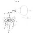
- FIG. 1 is a schematic construction diagram of a multipurpose projector 100 according to a first embodiment of the present invention
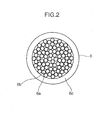
- FIG. 2 is a schematic section of an input/output plane of a fiber bundle 6 according to the first embodiment of the present invention.
- the multipurpose projector 100 shown in FIG. 1 is provided with laser beam sources 1r, 1g and 1b, an illumination optical system 2, a spatial modulation element 3, a multiplexing prism 4, a reduction projection optical system 5, a fiber bundle 6, a projection angle adjusting mechanism 7 and a projection lens 8.
- the laser beam sources 1r, 1g and 1b correspond to an example of a laser beam source and the illumination optical system 2
- the spatial modulation element 3, the multiplexing prism 4 and the reduction projection optical system 5 correspond to an example of an optical guide unit.
- the laser beam source 1r emits a red laser beam having a directivity
- the laser beam source 1g emits a green laser beam having a directivity
- the laser beam source 1b emits a blue laser beam having a directivity.
- the respective red, green and blue laser beams emitted from the laser beam sources 1r, 1g and 1b are shaped by the illumination optical system 2 to illuminate the spatial modulation element 3.
- the illumination optical system 2 is comprised of a rod integrator and a relay lens and shapes the respective red, green and blue laser beams to have rectangular and uniform intensity distributions suitable for the illumination of the spatial modulation element 3.
- the spatial modulation element 3 is comprised of a transmissive liquid crystal and a polarizing plate, modulates the laser beams of the respective colors and emits two-dimensionally modulated laser beams.
- the modulated red, green and blue laser beams are so multiplexed by the multiplexing prism 4 as to have the axes thereof aligned and incident on the reduction projection optical system 5.
- the reduction projection optical system 5 reduces and images the modulated laser beams on an input plane of the fiber bundle 6 and guides the modulated laser beams to respective cores of the fiber bundle 6.
- the fiber bundle 6 has a bundled structure of fibers as shown in FIG. 2 and includes a plurality of cores 6a, a cladding 6b and a coating 6c.
- the respective cores 6a are covered by the cladding 6b having a lower refractive index than the cores 6a.
- the cladding 6b is present between the cores 6a. Claddings 6b may be separated without being shared by the respective cores 6a and void spaces or spaces filled with another resin material may be present between the claddings 6b.
- the coating 6c covers the plurality of cores 6a and the cladding 6b.
- the fiber bundle 6 of this embodiment arrangements of the cores 6a in light input plane and output plane are determined and an image on the input plane can be transmitted to the output plane.
- the fiber bundle 6 is bendable and can be handled as one wire material together with the coating 6c.
- the cladding 6b between the plurality of cores 6a is preferably minimized in size in order to increase input efficiency. It is sufficient for the fiber bundle 6 to include the plurality of cores 6a and to be able to guide light, and the material and shape of the fiber bundle 6 are not particularly limited.
- the projection angle adjusting mechanism 7 is disposed on the side of the output plane of the fiber bundle 6 and freely adjusts projection angles of the laser beams to be projected from the projection lens 8 via the fiber bundle 6.
- the projection lens 8 is disposed on the output plane of the fiber bundle 6.
- the projection lens 8 enlarges and projects the modulated laser beams guided by the fiber bundle 6 to a display space 12.
- the display space 12 for displaying the modulated laser beams can be arbitrarily moved by the projection angle adjusting mechanism 7.
- the projection angle adjusting mechanism 7 in this embodiment can integrally move the output plane of the fiber bundle 6 and the projection lens 8, the present invention is not particularly limited to this and only the output plane of the fiber bundle 6 may be moved.
- the laser beams guided by the fiber bundle 6 have directivities. Thus, light can be coupled to the cores 6a of the fiber bundle 6 with high efficiency while image information is given to the laser beams through modulation.
- the light that can be input to the fiber bundle 6 is determined by a total area of the cores 6a and a fiber numerical aperture determined by the refractive indices of the cores 6a and the cladding 6b.
- the total area of the cores 6a can be small and light can be coupled with high efficiency while the fiber bundle 6 is permitted to be bendable.
- the multipurpose projector 100 of this embodiment is provided with the fiber bundle 6 including the plurality of cores 6a fixedly arranged on the input and output planes, the projection lens 8 for enlarging and projecting the laser beams emerging from the fiber bundle 6 to the display space, and the projection angle adjusting mechanism 7 disposed on the side of the output plane of the fiber bundle 6 for adjusting the projection angles of the laser beams to be projected from the projection lens 8.
- the modulated light can be enlarged and projected to the arbitrary display space 12.
- the display space 12 can be simultaneously limited by a modulation pattern of the laser beams, wherefore the display space 12 can be freely operated.
- the modulation pattern of the laser beams can illuminate the display space and decorate the space with colored light in addition to displaying an image and adding information to the display space.
- the multipurpose projector 100 of this embodiment can freely operate and enlarge the display space 12 thereof to extend its application not only to image display, but also illumination, decoration and the like of a space with colored light.
- the multipurpose projector 100 of this embodiment by installing the multipurpose projector 100 of this embodiment on the ceiling of a room, it is possible to illuminate an arbitrary place of the room, use a desktop or a wall as a display and realize an augmented reality in the room.
- the laser beam sources 1r, 1g and 1b of three colors of red, green and blue are used in the multipurpose projector 100, a laser beam source of only one color or laser beam sources of four or more colors may be used.
- Laser beam sources having directivities such as semiconductor lasers, solid-state lasers, gas lasers and wavelength conversion lasers can be used as the laser beam sources 1r, 1g and 1b.
- the laser beam source of one color may be a laser beam source including a plurality of laser emission apertures, and a plurality of emitted laser beams may not have the same center wavelength.
- ⁇ L denotes a 1/e 2 spreading half angle of a laser beam emitted from the laser beam source of one color
- S L denotes an emission aperture area of the laser beam source
- S F denotes a cross-sectional area of the fiber bundle 6 excluding the coating 6c
- NA F denotes a numerical aperture of the fiber bundle 6.
- the input efficiency of the laser beams to the fiber bundle 6 can be increased.
- the illumination optical system 2 may shape the beams so that the light intensity distributions are suitable for the spatial modulation element 3 and can take various constructions. In other words, a holographic optical element and the like can be used besides the rod integrator. Further, in the case of not using the spatial modulation element 3, the illumination optical system 2 may be omitted.
- a screen size Ss of the spatial modulation element 3 a laser beam emission numerical aperture NA S of the spatial modulation element 3, the cross-sectional area S F of the fiber bundle 6 excluding the coating 6c and the numerical aperture NA F of the fiber bundle 6 preferably satisfy the following equations (2) and (3).
- a pixel number of the spatial modulation element 3 and a total number of the cores of the fiber bundle 6 need not coincide and may differ. It is not necessary to strictly position the pixels and the cores in a one-to-one relationship.
- An arrangement of the cores of the fiber bundle 6 is preferably non-periodically displaced with respect to an arrangement of the pixels of the spatial modulation element 3. By non-periodically displacing the cores, moire in a projected image can be prevented.
- the cores of the fiber bundle 6 can be non-periodically arranged by randomly and most densely filling a plurality of fibers whose core diameters differ in a range of ⁇ 1 ⁇ m within the coating.
- the core diameters in the fiber bundle 6 randomly vary and the cores of the fiber bundle 6 can be non-periodically arranged.
- the cores of the fiber bundle 6 can be non-periodically arranged.
- the pixel number of the spatial modulation element 3 is preferably greater than the total number of the cores of the fiber bundle 6. In this way, moire in a projected image can be prevented, and laser beams can be projected while a reduction of pixel information at the time of modulation by the spatial modulation element 3 is compensated for by retaining incident angle distribution information to the cores from the spatial modulation element 3 in the fiber bundle 6.
- the reduction projection optical system 5 of the first embodiment reduces and projects an image of the spatial modulation element 3 and focuses it on the input plane of the fiber bundle 6. By focusing the image of the spatial modulation element 3 on the input plane, a high-quality image in focus can be transmitted.
- the reduction projection optical system 5 is a single lens in FIG. 1 , it may be comprised of a plurality of lenses.
- the reduction projection optical system 5 preferably has a magnification changing function (zooming function). When the pixel number of the spatial modulation element 3 and the total number of the cores of the fiber bundle 6 do not coincide, the zooming function of the reduction projection optical system 5 can change an information range and a resolution necessary for an image to be projected.
- the cores 6a are composed of GeO 2 -doped quartz and the cladding 6a between the cores is composed of F-doped quartz.
- the number of the cores is 100,000
- the fiber numerical aperture is 0.35
- the fiber cross-sectional area is 1.8 mm 2 .
- the resolution is 300,000 pixels as VGA (Video Graphics Array) standard
- a screen size is 44 mm 2
- the emission numerical aperture is 0.06, so that the above equations (2) and (3) are satisfied.
- a semiconductor laser having a wavelength of 635 nm is used as the red laser beam source 1r
- a wavelength conversion laser having a wavelength of 532 nm is used as the green laser beam source 1g
- a semiconductor laser having a wavelength of 445 nm is used as the blue laser beam source 1b.
- the red laser beam source 1r has a largest area and includes six emission apertures, wherein an emission aperture area is 900 ⁇ m 2 and divergence angles are 40° and 10°. However, the above relationships between the fiber bundle 6 and the laser beam source 1r are satisfied.
- the fibers of the fiber bundle 6 are preferably multi-mode fibers.
- the length of the fiber bundle 6 is preferably 1 m or longer. By setting the length at 1 m or longer, a reduction of the above coherence can be realized and the projection angle adjusting mechanism 7 can smoothly perform its operation by loosening the fiber bundle 6 (providing a bent portion) between the input and output planes.
- the lengths of the adjacent cores of the fiber bundle 6 from the input plane to the output plane may differ.
- the projection angle adjusting mechanism 7 includes a two-axis angle adjusting mechanism and can freely adjust a direction of the output plane of the fiber bundle 6 in an angle adjustment range.
- the fiber bundle 6 is loosened from an input end to an output end as shown in FIG. 1 , so that no large stress acts even if the projection angle is adjusted.
- the projection angle adjusting mechanism 7 moves the projection lens 8 together with the output plane of the fiber bundle 6 to adjust the projection angle.
- the projection angle adjusting mechanism 7 uses a two-axis gonio stage.
- a coverage angle adjusting mechanism in a monitoring camera or the like is, for example, used, the output end of the fiber bundle 6 and the projection lens 8 are integrally mounted on the two-axis gonio stage capable of changing an angle in vertical and lateral directions, and the respective stages are rotated by specified angles by a driver.
- the angle may be changed in vertical and lateral directions, for example, by integrally mounting the output end of the fiber bundle 6 and the projection lens 8 on one end of a wire such as in an endoscope and pulling the other end of the wire by a driver.
- the projection angle adjusting mechanism 7 can simultaneously increase an area to be irradiated and the number of display pixels by being quickly operated. At this time, an operation frequency of the projection angle adjusting mechanism 7 is preferably 10 Hz or higher.
- the projection angle adjusting mechanism 7 preferably includes a mechanism for moving the output end of the fiber bundle 6 in a lengthwise direction of the fiber bundle 6. By moving the output end of the fiber bundle 6, a distance between the output end of the fiber bundle 6 and the projection lens 8 can be changed and a change of an illumination angle for the display space 12 and image zooming can be freely performed.
- the projection angle adjusting mechanism 7 may not only move the output end of the fiber bundle 6 in the lengthwise direction of the fiber bundle 6, but also move the projection lens 8 in the lengthwise direction of the fiber bundle 6.
- the projection angle adjusting mechanism 7 repeatedly vibrates the projection lens 8 during a period of projecting laser beams from the projection lens and adjusts the projection angle of the projection lens 8 during the movement of the display space. Since laser beams are coherent, granular noise called speckle noise is likely to occur in a projected image. Also in the multipurpose projector 100 of this embodiment, speckle noise needs to be removed.
- the projection angle adjusting mechanism 7 can remove the speckle noise by causing the projection lens 8 to repeatedly make microscopic movements in the order of ⁇ m during image projection and temporally averaging the speckle noise.
- the mechanism for vibrating the projection lens 8 can be easily realized by using a driver such as a piezoelectric element or an ultrasonic motor.
- the projection lens 8 is comprised of a plurality of lenses and enlarges and projects an image of the output end of the fiber bundle 6 to the display space.
- the projection lens 8 includes an auto-focusing mechanism and performs a focus adjustment as the display space 12 is moved. This enables a high-quality image to be displayed while the display space 12 is changed.
- the projection lens 8 may also include an auto-zooming function. This leads to increased convenience by enlarging or reducing an image to a size intended by a user.
- illumination is carried out by not only changing the modulation pattern of the laser beams, but also setting the projection lens 8 in a defocus state.
- the projection angle adjusting mechanism 7 causes the display space 12 to be illuminated in the defocus state by relatively changing the distance between the output plane of the fiber bundle 6 and the projection lens 8. Since the display space 12 is illuminated in the defocus state, dark parts caused by the cladding of the fiber bundle 6 disappear and the display space 12 can be uniformly illuminated.
- FIG. 3 is a schematic construction diagram of a multipurpose projector 200 according to a second embodiment of the present invention.
- the same construction as the first embodiment is identified by the same reference numerals and not described.
- the multipurpose projector 200 shown in FIG. 3 is provided with laser beam sources 1r, 1g and 1b, an illumination optical system 2, a spatial modulation element 3, a multiplexing prism 4, a reduction projection optical system 5, a fiber bundle 6, a projection angle adjusting mechanism 7, a projection lens 8, a switching element 9, a speckle noise removing mechanism 10 and a main projection lens 11.
- the multipurpose projector 200 has the same construction as the multipurpose projector 100 up to the reduction projection optical system 5.
- the main projection lens 11 enlarges and projects modulated laser beams to a display space 13 different from the display space 12, to which laser beams are projected via the fiber bundle 6, without guiding them to the fiber bundle 6.
- the switching element 9 is switched to split the modulated laser beams to the main projection lens 11 and to the fiber bundle 6 or guide the laser beams only to either one of them.
- the speckle noise removing mechanism 10 is arranged on an imaging plane of an image reduced and projected at the side of the main projection lens 11, i.e. at a position equivalent to an input plane of the fiber bundle 6, and temporally changes the phase of light.
- the multipurpose projector 200 of the second embodiment includes the main projection lens for enlarging and projecting the modulated light in addition to the projection lens 8 on the output plane of the fiber bundle 6.
- the modulated laser beams can be displayed with high image quality using the main projection lens 11 for the specific display space 13.
- it is suitable in the case of displaying an image in a display space used as a main display in a room.
- the switching element 9 switches the modulated laser beams only to one of the main projection lens 11 and the fiber bundle 6 and splits them at a suitable ratio when the multipurpose projector 200 includes two types of projection means, i.e. the main projection lens 11 and the fiber bundle 6.
- the switching element 9 is a movable mirror and is switched to transmit the modulated light toward the main projection lens 11 and reflect them toward the fiber bundle 6.
- the multipurpose projector 200 of this embodiment includes an optical element for splitting or switching the modulated light to or between the main projection lens 11 and the fiber bundle 6.
- the multipurpose projector 200 of this embodiment can freely provide an image in the display space by using either one of the main projection lens 11 and the fiber bundle 6 or simultaneously using both.
- efficiently modulated laser beams can propagate toward the projection side.
- the switching element 9 may be arranged between the spatial modulation element 3 and the fiber bundle 6 and incorporated into the reduction projection optical system 5 or may be arranged between the reduction projection optical system 5 and the spatial modulation element 3.
- a reflective polarizing element is preferably used as the switching element 9.
- a transmissive liquid crystal having no polarizing plate at an output side is used as the spatial modulation element 3 and a wire-grid type reflective polarizing element is used as the switching element 9.
- the reflective polarizing element splits or switches light to or between the main projection lens 11 and the fiber bundle 6 depending on the polarization direction determined by the spatial modulation element 3.
- the spatial modulation element 3 performs modulation by rotating the polarization direction toward the main projection lens 11 so as to obtain a specified image. Unnecessary light whose polarization direction is not rotated is guided to the fiber bundle 6. At this time, the unnecessary light from the fiber bundle 6 is used for illumination by setting the projection lens 8 in a defocus state.
- the multipurpose projector 200 includes the spatial modulation element 3 for rotating the polarization direction and the reflective polarizing element for splitting laser beams, wherefore unnecessary light, which has not be conventionally utilized, can also be utilized.
- a projection direction can also be switched by using the optical component or modulation element for rotating the polarization direction such as a wave plate and the reflective polarizing element for splitting laser beams.
- a split ratio can be freely changed according to an angle of rotation of the polarization direction.
- a PBS polarization beam splitter
- the modulated light projected from the output plane of the fiber bundle 6 and that projected from the main projection lens 11 may be in a positive/negative relationship.
- Positive and negative refer to as images whose darkness is reversed.
- either ones of the modulated laser beams enlarged and projected from the projection lens 8 and those enlarged and projected from the main projection lens 11 may form a positive image, whereas the others may form a negative image.
- the light modulated to have a positive/negative relationship is split to the fiber bundle 6 and the main projection lens 11 and projected.
- the modulated laser beams enlarged and projected from the projection lens 8 form a negative image and those enlarged and projected from the main projection lens 11 form a positive image.
- the speckle noise removing mechanism 10 at the side of the main projection lens 11 is arranged on an imaging plane of the modulated light.
- the speckle noise removing mechanism 10 is arranged on the imaging plane of the reduction projection optical system 5.
- the speckle noise removing mechanism 10 of the second embodiment temporally changes the phase by vibrating a holographic diffuser in an in-plane direction of the imaging plane.
- the speckle noise removing mechanism 10 temporally averages and removes speckle noise as laser coherence noise. Further, the speckle noise removing mechanism 10 can remove only the speckle noise while maintaining the image quality by being arranged on the imaging plane.
- the reduction projection optical system 5 forms the imaging plane on the input plane of the fiber bundle 6 and the imaging plane on an insertion surface of the speckle noise removing mechanism 10 at the side of the main projection lens 11. Further, since the imaging surface has a very small area in this embodiment, the speckle noise removing mechanism 10 can be miniaturized.
- the speckle noise removing mechanism 10 vibrates the holographic diffuser in the in-plane direction of the imaging plane by using a driver such as a piezoelectric element or an ultrasonic motor.
- the multipurpose projector 200 includes the main projection lens 11 for enlarging and projecting an imaging plane, which is reduced and projected, to the other display space without guiding it to the fiber bundle 6.
- the main projection lens 11 can be miniaturized.
- the main projection lens 11 and the projection lens 8 on the output plane of the fiber bundle 6 may have the same design.
- FIG. 4 is a schematic construction diagram of a multipurpose projector 300 according to a third embodiment of the present invention.
- the same construction as the first and second embodiments is identified by the same reference numerals and not described.
- the multipurpose projector 300 shown in FIG 4 is provided with a laser beam source 1a, an illumination optical system 2, a reduction projection optical system 5, a projection lens 8, a speckle noise removing mechanism 10, a main projection lens 11, a spatial modulation element 31, a fiber bundle 61, a coupling lens 81 and a reflective polarizing element 91.
- the illumination optical system 2, the reduction projection optical system 5 and the spatial modulation element 31 correspond to an example of the optical guide unit.
- the laser beam source 1a is a unit of three laser beam sources of three red, green and blue colors and emits laser beams of different colors successively in the order of, e.g. red, green, blue, red, and so on.
- Laser beams emitted from the laser beam source 1a are shaped by the illumination optical system 2 to illuminate the spatial modulation element 31.
- the spatial modulation element 31 is composed of transmissive liquid crystal and modulates the beams of the respective colors in a time-sharing manner.
- the modulated laser beams are reduced and projected by the reduction projection optical system 5.
- the reduced and projected laser beams are split toward the fiber bundle 61 and the main projection lens 11 by the reflective polarizing element 91.
- an output aperture of the fiber bundle 61 is connected to the illumination optical system 2 via the coupling lens 81 when an image is projected only from the main projection lens 11.
- Light guided from the reflective polarizing element 91 to the fiber bundle 61 is incident on the illumination optical system 2 via the projection lens 8 and the coupling lens 81 and mixed with light emitted from the laser beam source 1a by a rod integrator 14.
- the intensity of light emitted from the laser beam source 1a is modulated in accordance with an image signal input to the spatial modulation element 31 so that the peak luminance and white color of an image projected from the main projection lens 11 lie in fixed ranges.
- the laser beam source 1a calculates the luminance of the image signal input to the spatial modulation element 31 for the entire screen and modulates the intensities of laser beams to be emitted according to the calculated entire luminance.
- the intensity of the light emitted from the laser beam source 1a is 0.75 if one half of the screen is white and the remaining half is black while being 0.63 if 1/4 of the screen is white and the remainder is black.
- an image for which the intensity of Light emitted from the laser beam source 1a conventionally needs to be 1, can be displayed with an output equal to or below 1. Further, in the case of a dark image whose peak luminance is low, the intensity of light emitted from the laser beam source 1a can be further suppressed by setting low intensity for the light emitted from the laser beam source 1a and controlling a modulation signal to increase the transmittance of the spatial modulation element 31.
- the output aperture of the fiber bundle 61 is connected to the illumination optical system 2, light output from the fiber bundle 61 is mixed with light for illuminating the spatial modulation element 31 and the light intensity of the laser beam source 1a is modulated in accordance with an image signal input to the spatial modulation element 31.
- the light intensity of the laser beam source 1a is set low, power saving attributable to the use of the fiber bundle 61 is possible by displaying an image in the fixed range of the peak luminance and in a fixed color range.
- FIG. 5 is a schematic construction diagram of a multipurpose projector 400 according to a fourth embodiment of the present invention.
- the same construction as the first to third embodiments is identified by the same reference numerals and not described.
- the multipurpose projector 400 shown in FIG. 5 is provided with a laser beam source 1a, an illumination optical system 2, a fiber bundle 6, a projection angle adjusting mechanism 7, a spatial modulation element 31, a condensing optical system 51 and a projection lens 80.
- the illumination optical system 2, the spatial modulation element 31 and the condensing optical system 51 correspond to an example of the optical guide unit.
- Laser beams emitted from the laser beam source 1a are shaped by the illumination optical system 2 to illuminate the spatial modulation element 31.
- the laser beams emerging from the spatial modulation element 31 are condensed on an input plane of the fiber bundle 6 by the condensing optical system 51.
- the condensing optical system 51 does not form an image on the input plane of the fiber bundle 6, and a focus of the condensing optical system 51 is located near the input plane of the fiber bundle 6.
- the projection lens 80 is mounted near an output plane of the fiber bundle 6 for enlarging and forming an image of the modulated laser beams in a display space 12.
- an image is projected to the display space 12 without missing a part of modulation information even if the fiber bundle 6 is defective.
- a Fourier transform pattern of a modulation signal is transmitted by the fiber bundle 6 without forming an image on the input plane of the fiber bundle 6, and an image is formed in the display space 12 by the projection lens 80.
- FIG. 6 is a schematic construction diagram of a multipurpose projector 500 according to a fifth embodiment of the present invention.
- the same construction as the first to fourth embodiments is identified by the same reference numerals and not described.
- the multipurpose projector 500 shown in FIG. 6 is provided with laser beam sources 1r, 1g and 1b, a fiber bundle 6, a projection angle adjusting mechanism 7, a projection lens 8, a speckle noise removing mechanism 10, a main projection lens 11, an illumination optical system 21, a scan mirror 32 and a condenser lens 52.
- the illumination optical system 21, the scan mirror 32 and the condenser lens 52 correspond to an example of the optical guide unit.
- Laser beams of the respective red, green and blue colors emitted from the laser beam sources 1r, 1g and 1b have the axes thereof aligned by the illumination optical system 21 and are shaped.
- the illumination optical system 21 includes a collimator lens, a dichroic mirror and a beam expander.
- the laser beam sources 1r, 1g and 1b modulate output intensities in accordance with an image signal.
- the condenser lens 52 narrows the laser beams so that the laser beams are gathered on an input plane of the fiber bundle 6.
- the scan mirror 32 two-dimensionally scans the beams and performs spatial modulation to the laser beams in accordance with intensity modulations of the laser beam sources 1r, 1g and 1b.
- the scan mirror 32 two-dimensionally scans the laser beams by operating along two axes.
- the spatially modulated laser beams are focused on the input plane of the fiber bundle 6 by the condenser lens 52, and this image is transmitted to an output plane of the fiber bundle 6.
- the projection angle adjusting mechanism 7 and the projection lens 8 are mounted on the fiber bundle 6 and the spatially modulated laser beams are enlarged and projected to an arbitrary display space 12.
- the projection angle adjusting mechanism 7 repeatedly vibrates the projection lens 8 during the projection of the laser beams to remove speckle noise.
- the laser beams are spatially modulated by the intensity modulations of the laser beam sources 1r, 1g and 1b and the two-dimensional scanning of the scan mirror 32 and the scanned laser beams are condensed on the input plane of the fiber bundle 6 by the condenser lens 52, thereby forming an imaging plane of the spatially modulated light on the input plane of the fiber bundle 6. Since only the imaging plane is formed on the input plane of the fiber bundle 6 having a very small area without using a spatial modulation element, the optical system can be miniaturized and simplified, which enables the miniaturization and cost reduction of the apparatus.
- the condenser lens 52 may have a function of condensing beams on the input plane of the fiber bundle 6, and the condenser lens 52 may be incorporated into the illumination optical system 21 or arranged between the scan mirror 32 and the fiber bundle 6.
- the scan mirror 32 may be comprised of two mirrors. Not only a reflective mirror, but also a diffractive or refractive mirror may be used as the scan mirror 32 to perform two-axis scanning.
- the multipurpose projector 500 can also form an imaging plane of spatially modulated light except on the input plane of the fiber bundle 6 by changing a scanning angle of the scan mirror 32 and enlarges and projects an image to another display space 13 via the main projection lens 11 without guiding light to the fiber bundle 6.
- the speckle noise removing mechanism 10 is arranged on an imaging plane at the side of the main projection lens 11 and removes speckle noise by temporally changing the phases of the laser beams.
- the multipurpose projector 500 can switch a projection pattern of projecting only from the fiber bundle 6, a projection pattern of projecting only from the main projection lens 11 and a projection pattern of projecting from both the fiber bundle 6 and main projection lens 11 by switching the scanning angle of the scan mirror 32 and an intensity modulation pattern of the laser beam sources 1r, 1g and 1b.
- a switching mirror or the like may be separately provided.
- the imaging plane of spatially modulated light is formed other than on the input plane of the fiber bundle by adjusting the scanning angle of the scan mirror 32 and an image on the formed imaging plane is enlarged and projected to another display space 13 by the main projection lens 11 without being guided to the fiber bundle 6.
- the main projection lens 11 In the case of guiding laser beams to the fiber bundle 6 and projecting them from the fiber bundle 6, there is a problem that the quality of an image of the modulated laser beams is deteriorated depending on the number of the cores of the fiber bundle 6 and the shape of the cladding.
- modulated laser beams can be displayed in a specific display space 13 with high image quality using the main projection lens 11.
- This embodiment is particularly suitable in the case of displaying an image in a display space used as a main display in a room.
- illumination, decoration and addition of various pieces of information can be simultaneously performed in the display space 12 and the main display (other display space 13). Since the imaging plane having a very small area formed by the condenser lens 52 is used, it is possible to miniaturize the main projection lens 11 and the speckle noise removing mechanism 10.
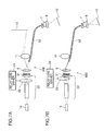
- FIGS. 7A and 7B are schematic construction diagrams of a multipurpose projector 600 according to a sixth embodiment.
- FIG. 7A shows a schematic construction of the multipurpose projector 600 in the case of guiding laser beams to a fiber bundle and a main projection lens
- FIG. 7B shows a schematic construction of the multipurpose projector 600 in the case guiding laser beams only to the fiber bundle.
- FIGS. 7A and 7B the same construction as the first to fifth embodiments is identified by the same reference numerals and not described.
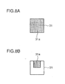
- FIG. 8A is a diagram showing an illumination region of a spatial modulation element of the multipurpose projector 600 shown in FIG. 7A
- FIG. 8B is a diagram showing an illumination region of the spatial modulation element of the multipurpose projector 600 shown in FIG. 7B .
- the multipurpose projector 600 shown in FIGS. 7A and 7B is provided with a laser beam source 1a, a reduction projection optical system 5, a projection angle adjusting mechanism 7, a projection lens 8, a main projection lens 11, an illumination optical system 22, a relay lens 23, a relay lens driver 24, a spatial modulation element 31 and a fiber bundle 62.
- the relay lens 23 and the relay lens driver 24 correspond to an example of an illumination area reducing unit
- the illumination optical system 22 and the spatial modulation element 31 correspond to an example of the optical guide unit.
- a laser beam emitted from the laser beam source 1a is shaped by the illumination optical system 22 including the relay lens 23 to illuminate the spatial modulation element 31.
- the spatial modulation element 31 modulates the incident laser beam.
- the entire area of the spatial modulation element 31 is illuminated as shown in FIG. 7A .
- an illumination area 31a illuminated by the illumination optical system 22 spreads over the entire surface of the spatial modulation element 31.
- the relay lens driver 24 conforms an optical axis of the laser beam to the substantially center of the relay lens 23 without moving the relay lens 23.
- the laser beam modulated by the spatial modulation element 31 is projected to an input plane of the fiber bundle 62 and an imaging plane at the side of the main projection lens 11 by the reduction projection optical system 5.
- the laser beam incident on the fiber bundle 62 is projected to a display space 12 via the projection lens 8.
- An image formed at the side of the main projection lens 11 is projected to another display space 13 by the main projection lens 11.
- the illumination area of the spatial modulation element 31 is reduced in size as shown in FIG. 7B .
- the relay lens driver 24 shifts the relay lens 23 upward and in an optical axis direction.
- the illumination area 31a is reduced to be present only in an upper part of the spatial modulation element 31 as shown in FIG. 8B .
- the upper part of the spatial modulation element 31 corresponds to the input plane of the fiber bundle 62, and illumination is centered on an area where light is guided to the fiber bundle 62 to reduce the illumination area 31a in size.
- the laser beam modulated by the spatial modulation element 31 is projected only to the input plane of the fiber bundle 62 by the reduction projection optical system 5.
- the laser beam incident on the fiber bundle 62 is projected to the display space 12 via the projection lens 8.
- the relay lens 23 may be shifted to reduce the size of the illumination area 31a of the spatial modulation element 31 as compared with the case where light is guided to both the fiber bundle 62 and the main projection lens 11.
- the illumination area of the spatial modulation element 31 is reduced in size in the case of guiding light only to the input plane of the fiber bundle 62. If no switching element is present although the main projection lens 11 is required, there is a problem of increasing a light quantity loss if only the fiber bundle 62 is used. However, in this embodiment, the light quantity loss can be reduced by controlling the position of the illumination area of the spatial modulation element 31 in accordance with how the multipurpose projector is used.
- FIG 9 is a schematic construction diagram of a multipurpose projector 700 according to a seventh embodiment of the present invention.
- the same construction as the first to sixth embodiments is identified by the same reference numerals and not described.
- the multipurpose projector 700 shown in FIG. 9 is provided with a laser beam source 1a, an illumination optical system 2, a projection angle adjusting mechanism 7, a projection lens 8, a spatial modulation element 31, a fiber bundle 65 and an input plane vibrating mechanism 66.
- the input plane vibrating mechanism 66 is arranged on an input plane of the fiber bundle 65 to vibrate the input plane in an in-plane direction.
- the input plane vibrating mechanism 66 vibrates the input plane of the fiber bundle 65 in the in-plane direction to temporally displace cores for guiding light when a modulated laser beam is incident on the fiber bundle 65.
- Speckle noise as coherence noise of the laser beam can be temporally averaged and removed by temporally displacing the cores for guiding the laser beam to differ the cores. Further, by displacing the cores for guiding light, an image with no defect can be projected even if some of the cores are defective.
- a displacement of an image caused by the vibration of the input plane by the input plane vibrating mechanism 66 may be compensated for by finely vibrating the output plane of the fiber bundle 65 by the projection angle adjusting mechanism 7.
- speckle noise can be removed while good image quality is maintained.
- FIGS. 10A to 10D are diagrams showing an operation of changing the orientation of an image to be projected in a multipurpose projector 800 according to an eighth embodiment of the present invention.
- FIG. 10A is a schematic construction diagram of the multipurpose projector 800 according to the eighth embodiment of the present invention
- FIG. 10B is a diagram showing an operation of rotating an image to be projected by an angle below 90°
- FIG. 10C is a diagram showing an operation of rotating an image to be projected by an angle of 180°
- FIG. 10D is a diagram showing an operation of rotating an image to be projected by an angle equal to or larger than 90° and below 180°.
- FIGS. 10A to 10D the same construction as the first to seventh embodiments is identified by the same reference numerals and not described.
- a projection angle adjusting mechanism 71 also adjusts an angle of the fiber bundle 6 in a direction of axial rotation. As shown in FIG. 10B , the projection angle adjusting mechanism 71 axially rotates the fiber bundle 6 in the case of rotating the image by an angle below 90°. Further, as shown in FIG. 10C , a spatial modulation element 31 switches the image to a modulation pattern rotated by 180° without using the projection angle adjusting mechanism 71 in the case of rotating the image by an angle of 180°. Furthermore, as shown in FIG. 10D , the spatial modulation element 31 switches a modulation pattern of a laser beam and the projection angle adjusting mechanism 71 axially rotates the fiber bundle 6 in the case of rotating the image by an angle equal to or larger than 90° and below 180°.
- the fiber bundle 6 is axially rotated by the projection angle adjusting mechanism 71 also in the case of rotating the image leftward by an angle below 90°.
- the modulation pattern of the laser beam is switched by the spatial modulation element 31 and the fiber bundle 6 is axially rotated by the projection angle adjusting mechanism 71 also in the case of rotating the image rightward by an angle equal to or larger than 90° and below 180°.
- the orientation of an image to be projected can be freely adjusted by axially rotating the fiber bundle 6. Further, in the case of axially rotating the fiber bundle 6 by an angle equal to or larger than 90°, a large stress may possibly act on the fiber bundle 6 to cause problems of enlarging a driving mechanism and fracturing the fiber.
- these problems are solved by combining the axial rotation of the fiber bundle 6 by the projection angle adjusting mechanism 71 and the switching of the modulation pattern of the laser beam by the spatial modulation element 31, wherefore the orientation of the image can be freely adjusted without exerting a large stress to the fiber bundle 6.
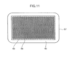
- FIG. 11 is a section of an input/output plane of a fiber bundle 67 according to a ninth embodiment of the present invention.
- the aggregated shape of cores 6a for guiding light is rectangular in the input and output planes. Since a projector using a fiber bundle frequently uses rectangular images whose aspect ratios are 16:9 or 4:3, the fiber bundle preferably has a rectangular shape instead of a conventional round shape.
- the aggregated shape of the cores is a rectangular shape with an aspect ratio of 16:9 or 4:3.
- a projector using the fiber bundle 67 of this embodiment has a projection angle adjusting mechanism and requires a reference direction for an operation of adjusting an angle of an output plane.
- the fiber bundle 67 has a rectangular cross-sectional shape.
- the fiber bundle 67 of the ninth embodiment is applicable to the fiber bundles of the multipurpose projectors according to the first to eighth embodiments.
- FIG 12 is a section of an input/output plane of a fiber bundle 68 according to a tenth embodiment of the present invention.
- Core diameters of the fiber bundle 68 differ in a central part and an outer peripheral part of the fiber bundle 68, wherein the core diameters in the outer peripheral part of the fiber bundle 68 are larger than those in the central part.
- An image projected using a fiber bundle has a problem that a peripheral part of the image becomes darker due to the eclipse of light when being incident on and emerging from the fiber bundle.
- an area ratio of the cores is increased to increase light utilization efficiency and the darkening of the peripheral part of the image is prevented by setting the core diameters in the outer peripheral part of the fiber bundle where light is easily eclipsed larger than those in the central part.
- a resolution of the central part of the image with a higher degree of attention can be increased as against that in the peripheral part by setting the core diameters in the central part of the fiber bundle smaller than those in the outer peripheral part. This embodiment is particularly suitable when a main part of information wished to be provided is present in a central part of an image.
- the fiber bundle 68 of the tenth embodiment can be applied as the fiber bundles of the multipurpose projectors according to the first to eighth embodiments.
- a method combining a spatial modulation element and a scan mirror may be used as a method for modulating a laser beam.
- the wavelength and shape of laser beams emitted from the laser beam source(s) are not particularly limited to those of the above first to tenth embodiments.
- a laser beams source having an array structure such as a multi-stripe structure or an external resonator type laser beam source may be used.
- the illumination optical system is also not particularly limited to those of the above first to tenth embodiments, and it is sufficient to obtain a beam shape necessary for laser beam modulation.
- a projector comprises a fiber bundle including a plurality of cores fixedly arranged on an input plane and an output plane; a laser beam source for emitting a laser beam having a directivity; an optical guide unit for modulating the laser beam emitted from the laser beam source and guiding the modulated laser beam to the input plane of the fiber bundle; a projection lens for enlarging and projecting the laser beam emerging from the output plane of the fiber bundle to a display space; and a projection angle adjusting mechanism disposed on the side of the output plane of the fiber bundle for adjusting a projection angle of the laser beam projected from the projection lens.
- the fiber bundle includes the plurality of cores fixedly arranged on the input plane and the output plane.
- a laser beam having a directivity is emitted from the laser beam source, and the laser beam emitted from the laser beam source is modulated and the modulated laser beam is guided to the input plane of the fiber bundle by the optical guide unit.
- the laser beam emerging from the output plane of the fiber bundle is enlarged and projected to the display space by the projection lens.
- the projection angle of the laser beam projected from the projection lens is adjusted by the projection angle adjusting mechanism disposed on the side of the output plane of the fiber bundle.
- the projector can have its projection space freely operated and enlarged to extend its application not only to image display, but also to illumination and decoration with colored light.
- a main projection lens for enlarging and projecting the laser beam modulated by the optical guide unit to another display space without guiding it to the fiber bundle.
- the laser beam modulated by the optical guide unit is enlarged and projected to the other display space by the main projection lens without being guided to the fiber bundle.
- the projection lens it is possible to illuminate and decorate the display space via the projection lens, add various pieces of information to the display space and display an image in the other display space via the main projection lens.
- an optical element for splitting or switching the laser beam modulated by the optical guide unit to or between the main projection lens and the fiber bundle.
- the laser beam modulated by the optical guide unit is split to or switched between the main projection lens and the fiber bundle by the optical element, an image can be freely formed in the display space.
- the optical element includes a reflective polarizing element
- the optical guide unit includes a modulation element or an optical component for rotating a polarization direction of the modulated laser beam
- the reflective polarizing element splits or switches the laser beam according to the polarization direction of the modulated laser beam.
- the cores of the fiber bundle are preferably non-periodically arranged. According to this construction, moire in a projected image can be prevented since the cores of the fiber bundle are non-periodically arranged.
- the number of the cores of the fiber bundle is preferably smaller than the number of pixels of a spatially modulated image.
- core diameters of the fiber bundle are preferably larger in an outer peripheral part than in a central part of the fiber bundle.
- the optical guide unit preferably includes a spatial modulation element for modulating the laser beam emitted from the laser beam source and a reduction projection optical system for reducing and projecting the laser beam modulated by the spatial modulation element to the input plane of the fiber bundle.
- a main projection lens for enlarging and projecting the laser beam reduced and projected by the reduction projection optical system to another display space without guiding it to the fiber bundle.
- the laser beam reduced and projected by the reduction projection optical system is enlarged and projected to the other display space by the main projection lens without being guided to the fiber bundle.
- the projection lens it is possible to illuminate and decorate the display space via the projection lens, add various pieces of information to the display space and display an image in the other display space via the main projection lens.
- the optical guide unit preferably includes a spatial modulation element for modulating the laser beam emitted from the laser beam source and, in the case of guiding the laser beam only to the input plane of the fiber bundle, an illumination area reducing unit for reducing an illumination area of the spatial modulation element.
- the illumination area of the spatial modulation element is reduced by the illumination area reducing unit in the case of guiding the laser beam only to the input plane of the fiber bundle.
- the illumination area reducing unit in the case of guiding the laser beam only to the input plane of the fiber bundle without reducing the illumination area of the spatial modulation element, more light passing through the spatial modulation element is lost without being incident on the fiber bundle.
- a light quantity loss can be reduced since only the light having passed through the reduced illumination area of the spatial modulation element is incident on the fiber bundle by reducing the illumination area of the spatial modulation element.
- the laser beam source modulates the light intensity of the laser beam
- the optical guide unit further includes a scanning mirror for scanning and spatially modulating the laser beam and a condenser lens for condensing the laser beam scanned by the scanning mirror on the input plane of the fiber bundle.
- the light intensity of the laser beam is modulated by the laser beam source, the laser beam is scanned by the scanning mirror and the laser beam being scanned is condensed on the input plane of the fiber bundle by the condenser lens.
- the laser beam is condensed on the input plane of the fiber bundle without using a spatial modulation element, wherefore the optical system can be miniaturized and simplified, which enables the miniaturization and cost reduction of the apparatus.
- a main projection lens for enlarging and projecting the modulated laser beam to another display space without guiding it to the fiber bundle is further provided, and that the scanning mirror scans an imaging plane of the laser beam to the fiber bundle and the main projection lens.
- the modulated laser beam is enlarged and projected to the other display space by the main projection lens without being guided to the fiber bundle, and the imaging plane of the laser beam is scanned to the fiber bundle and the main projection lens by the scanning mirror.
- the projection lens it is possible to illuminate and decorate the display space via the projection lens, add various pieces of information to the display space and display an image in the other display space via the main projection lens.
- speckle noise removing mechanism for temporally changing the phase of the laser beam enlarged and projected by the main projection lens.
- speckle noise can be removed by temporally changing the phase of the laser beam enlarged and projected by the main projection lens.
- the optical guide unit includes a spatial modulation element for modulating the laser beam emitted from the laser beam source and a condensing optical system for condensing the laser beam modulated by the spatial modulation element on the input plane of the fiber bundle without focusing it on the input plane of the fiber bundle, and that the projection lens enlarges and focuses the laser beam emerging from the output plane of the fiber bundle.
- the laser beam emitted from the laser beam source is modulated by the spatial modulation element, and the laser beam modulated by the spatial modulation element is condensed on the input plane of the fiber bundle by the condensing optical system without being focused on the input plane of the fiber bundle and the laser beam emerging from the output plane of the fiber bundle is enlarged and focused by the projection lens.
- the modulated laser beam is not focused on the input plane of the fiber bundle, wherefore an image at a specific position is not missed and modulation information of a fixed frequency or lower can be displayed in the display space even if some of the cores are defective.
- the projection angle adjusting mechanism repeatedly vibrates the projection lens during a period of projecting the laser beam from the projection lens, and that the projection angle of the laser beam projected from the projection lens is adjusted during a movement of the display space.
- the projection lens is repeatedly vibrated during the period of projecting the laser beam from the projection lens, and the projection angle of the laser beam projected from the projection lens is adjusted during the movement of the display space.
- speckle noise can be removed by being temporally averaged.
- an input plane vibrating mechanism for temporally vibrating the input plane of the fiber bundle in an in-plane direction. According to this construction, speckle noise can be removed by being temporally averaged since the input plane of the fiber bundle is temporally vibrated in the in-plane direction.
- the input and output planes of the fiber bundle preferably have rectangular shapes. According to this construction, references in two axes for the projection angle can be determined and the display space can be easily moved since the input and output planes of the fiber bundle have the rectangular shapes.
- either one of the modulated laser beam enlarged and projected by the projection lens and that enlarged and modulated by the main projection lens is a positive image and the other is a negative image.
- an image to be projected can be accentuated and interpolated since either one of the modulated laser beam enlarged and projected by the projection lens and that enlarged and modulated by the main projection lens is a positive image and the other is a negative image. It is also possible to project both positive and negative images to different display spaces and decorate the display space to illuminate the display space with light inverted from the entire image by setting the projection lens on the side of the fiber bundle in a defocus state.
- a coupling lens for coupling a laser beam emitted from the projection lens and a laser beam emitted from the laser beam source is further provided, and that the laser beam source modulates the light intensity of the laser beam to be emitted in accordance with an image signal input to the spatial modulation element.
- the laser beam emitted from the projection lens and the laser beam emitted from the laser beam source are coupled by the coupling lens, and the light intensity of the laser beam to be emitted is modulated in accordance with the image signal input to the spatial modulation element by the laser beam source.
- the intensity of the laser beam is reduced, an image can be displayed in a fixed range of peak luminance and in a fixed color range and power saving can be realized.
- the optical guide unit includes a spatial modulation element for modulating the laser beam emitted from the laser beam source, that the spatial modulation element switches a direction of a modulation pattern in the case of rotating the orientation of an image enlarged and projected from the projection lens by 180°, the projection angle adjusting mechanism axially rotates the projection lens in the case of rotating the orientation of the image enlarged and projected from the projection lens by an angle below 90°, and that the spatial modulation element switches the direction of the modulation pattern and the projection angle adjusting mechanism axially rotates the projection lens in the case of rotating the orientation of the image enlarged and projected from the projection lens by an angle equal to or larger than 90° and below 180°.
- the direction of the modulation pattern is switched in the case of rotating the orientation of the image enlarged and projected from the projection lens by 180°, and the projection lens is axially rotated in the case of rotating the orientation of the image enlarged and projected from the projection lens by an angle below 90°. Further, the direction of the modulation pattern is switched and the projection lens is axially rotated in the case of rotating the orientation of the image enlarged and projected from the projection lens by an angle equal to or larger than 90° and below 180°. Accordingly, the orientation of the image can be freely adjusted without exerting a large stress to the fiber bundle in the case of polarizing the orientation of an image enlarged and projected from the projection lens.
- the optical guide unit includes a spatial modulation element for modulating the laser beam emitted from the laser beam source, and that a screen size S S of the spatial modulation element, a laser beam emission numerical aperture NA S of the spatial modulation element, a cross-sectional area S F of the fiber bundle and a numerical aperture NA F of the fiber bundle satisfy the following equations (4) and (5).
- the screen size S S of the spatial modulation element, the laser beam emission numerical aperture NA S of the spatial modulation element, the cross-sectional area S F of the fiber bundle and the numerical aperture NA F of the fiber bundle satisfy the equations (4) and (5), input efficiency of the modulated laser beam to the fiber bundle can be maintained high and the miniaturization of an optical component between the spatial modulation element and the fiber bundle can also be realized.
- the projection angle adjusting mechanism preferably illuminates the display space in a defocus state by relatively changing a distance between the output plane of the fiber bundle and the projection lens. According to this construction, dark parts caused by a cladding of the fiber bundle disappear and the display space can be uniformly illuminated since the display space is illuminated in the defocus state.
- a projector of the present invention can not only present images and information in a space, but also be used for various spatial presentations such as illumination and decoration and is particularly suitable for the realization of augmented realities in various spaces.
Landscapes
- Physics & Mathematics (AREA)
- Engineering & Computer Science (AREA)
- Multimedia (AREA)
- Signal Processing (AREA)
- General Physics & Mathematics (AREA)
- Optics & Photonics (AREA)
- Marketing (AREA)
- Accounting & Taxation (AREA)
- Theoretical Computer Science (AREA)
- Business, Economics & Management (AREA)
- Projection Apparatus (AREA)
- Transforming Electric Information Into Light Information (AREA)
- Illuminated Signs And Luminous Advertising (AREA)
Applications Claiming Priority (2)
| Application Number | Priority Date | Filing Date | Title |
|---|---|---|---|
| JP2007238786 | 2007-09-14 | ||
| PCT/JP2008/002407 WO2009034694A1 (ja) | 2007-09-14 | 2008-09-03 | プロジェクタ |
Publications (3)
| Publication Number | Publication Date |
|---|---|
| EP2187259A1 EP2187259A1 (en) | 2010-05-19 |
| EP2187259A4 EP2187259A4 (en) | 2012-10-03 |
| EP2187259B1 true EP2187259B1 (en) | 2014-05-14 |
Family
ID=40451714
Family Applications (1)
| Application Number | Title | Priority Date | Filing Date |
|---|---|---|---|
| EP08830531.3A Not-in-force EP2187259B1 (en) | 2007-09-14 | 2008-09-03 | Projector |
Country Status (4)
| Country | Link |
|---|---|
| US (1) | US8251521B2 (ja) |
| EP (1) | EP2187259B1 (ja) |
| JP (1) | JP5147849B2 (ja) |
| WO (1) | WO2009034694A1 (ja) |
Families Citing this family (89)
| Publication number | Priority date | Publication date | Assignee | Title |
|---|---|---|---|---|
| GB0522968D0 (en) | 2005-11-11 | 2005-12-21 | Popovich Milan M | Holographic illumination device |
| US20160357094A1 (en) * | 2005-11-23 | 2016-12-08 | Fusao Ishii | Optics of projecor |
| GB0718706D0 (en) | 2007-09-25 | 2007-11-07 | Creative Physics Ltd | Method and apparatus for reducing laser speckle |
| US8068267B2 (en) * | 2008-09-30 | 2011-11-29 | Texas Instruments Incorporated | Speckle reduction in display systems that employ coherent light sources |
| JP5293746B2 (ja) | 2008-12-08 | 2013-09-18 | 三菱電機株式会社 | エレベーターの制御装置 |
| EP2196844B1 (en) * | 2008-12-10 | 2014-09-10 | Delphi Technologies, Inc. | A projection unit having a speckle suppression device based on piezoelectric actuating |
| JP2010152176A (ja) * | 2008-12-25 | 2010-07-08 | Mitsubishi Electric Corp | 投写型表示装置 |
| DE102009017940A1 (de) * | 2009-04-17 | 2010-10-21 | Storz Endoskop Produktions Gmbh | Endoskopisches System |
| US9335604B2 (en) | 2013-12-11 | 2016-05-10 | Milan Momcilo Popovich | Holographic waveguide display |
| US11726332B2 (en) | 2009-04-27 | 2023-08-15 | Digilens Inc. | Diffractive projection apparatus |
| US8269902B2 (en) * | 2009-06-03 | 2012-09-18 | Transpacific Image, Llc | Multimedia projection management |
| US8203600B2 (en) * | 2009-06-04 | 2012-06-19 | Transpacific Image, Llc | Projection-type stereoscopic display |
| US8786940B2 (en) * | 2009-12-07 | 2014-07-22 | Laser Light Engines, Inc. | Despeckling apparatus and method |
| US9939653B2 (en) | 2009-12-07 | 2018-04-10 | Projection Ventures Inc. | Despeckling stability |
| WO2011092807A1 (ja) * | 2010-01-27 | 2011-08-04 | Necディスプレイソリューションズ株式会社 | 投写型表示装置、および投写型表示装置の制御方法 |
| JP5540991B2 (ja) * | 2010-08-19 | 2014-07-02 | ソニー株式会社 | 光学装置および表示装置 |
| JP5796578B2 (ja) | 2010-09-08 | 2015-10-21 | 大日本印刷株式会社 | 投射装置および投射型映像表示装置 |
| WO2012072124A1 (en) * | 2010-12-01 | 2012-06-07 | Lemoptix Sa | A projection system |
| US20130107350A1 (en) * | 2010-12-07 | 2013-05-02 | Laser Light Engines, Inc. | Multiple Laser Despeckling |
| US20130021586A1 (en) * | 2010-12-07 | 2013-01-24 | Laser Light Engines | Frequency Control of Despeckling |
| US20130162952A1 (en) * | 2010-12-07 | 2013-06-27 | Laser Light Engines, Inc. | Multiple Laser Projection System |
| WO2012136970A1 (en) | 2011-04-07 | 2012-10-11 | Milan Momcilo Popovich | Laser despeckler based on angular diversity |
| US10670876B2 (en) | 2011-08-24 | 2020-06-02 | Digilens Inc. | Waveguide laser illuminator incorporating a despeckler |
| EP2995986B1 (en) | 2011-08-24 | 2017-04-12 | Rockwell Collins, Inc. | Data display |
| WO2016020630A2 (en) | 2014-08-08 | 2016-02-11 | Milan Momcilo Popovich | Waveguide laser illuminator incorporating a despeckler |
| US9164365B2 (en) * | 2011-11-08 | 2015-10-20 | Reald Inc. | Imaging path speckle mitigation |
| WO2013102759A2 (en) | 2012-01-06 | 2013-07-11 | Milan Momcilo Popovich | Contact image sensor using switchable bragg gratings |
| TWI443438B (zh) * | 2012-05-04 | 2014-07-01 | Young Optics Inc | 投影系統 |
| WO2013167864A1 (en) | 2012-05-11 | 2013-11-14 | Milan Momcilo Popovich | Apparatus for eye tracking |
| EP2883489A4 (en) * | 2012-08-08 | 2016-04-20 | Olympus Corp | FIBER UNIT |
| JP6186685B2 (ja) * | 2012-09-19 | 2017-08-30 | カシオ計算機株式会社 | 投影装置 |
| JP6205714B2 (ja) | 2012-11-13 | 2017-10-04 | 株式会社リコー | オートフォーカス装置、投射レンズ装置、及び画像投射装置 |
| JP6123249B2 (ja) * | 2012-11-16 | 2017-05-10 | セイコーエプソン株式会社 | プロジェクターおよびその制御方法 |
| US9933684B2 (en) * | 2012-11-16 | 2018-04-03 | Rockwell Collins, Inc. | Transparent waveguide display providing upper and lower fields of view having a specific light output aperture configuration |
| KR102274413B1 (ko) * | 2013-01-15 | 2021-07-07 | 매직 립, 인코포레이티드 | 초고해상도 스캐닝 섬유 디스플레이 |
| WO2014144997A1 (en) * | 2013-03-15 | 2014-09-18 | Olive Medical Corporation | System and method for removing speckle from a scene lit by a coherent light source |
| WO2014171134A1 (ja) * | 2013-04-18 | 2014-10-23 | パナソニック株式会社 | 投写型映像表示装置 |
| US10209517B2 (en) | 2013-05-20 | 2019-02-19 | Digilens, Inc. | Holographic waveguide eye tracker |
| US9219910B2 (en) * | 2013-07-25 | 2015-12-22 | Disney Enterprises, Inc. | Volumetric display system blending two light types to provide a new display medium |
| US9727772B2 (en) | 2013-07-31 | 2017-08-08 | Digilens, Inc. | Method and apparatus for contact image sensing |
| TW201508329A (zh) * | 2013-08-19 | 2015-03-01 | Hon Hai Prec Ind Co Ltd | 光源裝置 |
| JP6263917B2 (ja) * | 2013-09-17 | 2018-01-24 | ソニー株式会社 | 情報処理装置、情報処理方法及びコンピュータプログラム |
| CA2931776A1 (en) * | 2013-11-27 | 2015-06-04 | Magic Leap, Inc. | Virtual and augmented reality systems and methods |
| US9389424B1 (en) | 2014-04-02 | 2016-07-12 | Magic Leap, Inc. | Methods and systems for implementing a high resolution color micro-display |
| US9752761B2 (en) | 2014-07-16 | 2017-09-05 | Telebrands Corp. | Landscape light |
| WO2016020632A1 (en) | 2014-08-08 | 2016-02-11 | Milan Momcilo Popovich | Method for holographic mastering and replication |
| WO2016042283A1 (en) | 2014-09-19 | 2016-03-24 | Milan Momcilo Popovich | Method and apparatus for generating input images for holographic waveguide displays |
| WO2016046514A1 (en) | 2014-09-26 | 2016-03-31 | LOKOVIC, Kimberly, Sun | Holographic waveguide opticaltracker |
| FR3030956B1 (fr) * | 2014-12-18 | 2018-03-23 | Centre National De La Recherche Scientifique - Cnrs | Dispositif de transport et de controle d'impulsions lumineuses pour l'imagerie endo-microscopique sans lentille |
| CN111323867A (zh) | 2015-01-12 | 2020-06-23 | 迪吉伦斯公司 | 环境隔离的波导显示器 |
| EP3245551B1 (en) | 2015-01-12 | 2019-09-18 | DigiLens Inc. | Waveguide light field displays |
| CN107533137A (zh) | 2015-01-20 | 2018-01-02 | 迪吉伦斯公司 | 全息波导激光雷达 |
| JP2016136196A (ja) * | 2015-01-23 | 2016-07-28 | 雅史 高尾 | 投影装置 |
| US9632226B2 (en) | 2015-02-12 | 2017-04-25 | Digilens Inc. | Waveguide grating device |
| WO2016146963A1 (en) | 2015-03-16 | 2016-09-22 | Popovich, Milan, Momcilo | Waveguide device incorporating a light pipe |
| WO2016156776A1 (en) | 2015-03-31 | 2016-10-06 | Milan Momcilo Popovich | Method and apparatus for contact image sensing |
| USD824066S1 (en) | 2015-05-11 | 2018-07-24 | Telebrands Corp. | Light projector |
| USD816890S1 (en) | 2015-05-11 | 2018-05-01 | Telebrands Corp. | Light projector |
| USD766483S1 (en) | 2015-05-11 | 2016-09-13 | Telebrands Corp. | Light projector |
| USD778478S1 (en) | 2015-05-11 | 2017-02-07 | Telebrands Corp. | Light projector |
| EP3359999A1 (en) | 2015-10-05 | 2018-08-15 | Popovich, Milan Momcilo | Waveguide display |
| IL287642B (en) * | 2015-10-30 | 2022-07-01 | Seurat Tech Inc | Add-on and device creation system |
| US9879847B2 (en) | 2015-12-03 | 2018-01-30 | Telebrands Corp. | Decorative lighting apparatus having two laser light sources |
| JP6024841B1 (ja) * | 2016-01-27 | 2016-11-16 | 株式会社リコー | 照明装置、パターン照射装置およびシステム |
| EP3398007A1 (en) | 2016-02-04 | 2018-11-07 | DigiLens, Inc. | Holographic waveguide optical tracker |
| JP6699277B2 (ja) * | 2016-03-23 | 2020-05-27 | セイコーエプソン株式会社 | プロジェクター |
| JP6895451B2 (ja) | 2016-03-24 | 2021-06-30 | ディジレンズ インコーポレイテッド | 偏光選択ホログラフィー導波管デバイスを提供するための方法および装置 |
| JP6734933B2 (ja) | 2016-04-11 | 2020-08-05 | ディジレンズ インコーポレイテッド | 構造化光投影のためのホログラフィック導波管装置 |
| CN109561819B (zh) * | 2016-08-08 | 2021-10-01 | 索尼公司 | 内窥镜装置和内窥镜装置的控制方法 |
| US10382843B2 (en) * | 2016-08-24 | 2019-08-13 | Verizon Patent And Licensing Inc. | Colorless, directionless, contentionless, spaceless, and flexible grid reconfigurable optical node |
| US9778478B1 (en) * | 2016-10-04 | 2017-10-03 | Christine Digital Systems Usa, Inc. | Projector with image plane modal vibration for speckle reduction |
| EP3548939A4 (en) | 2016-12-02 | 2020-11-25 | DigiLens Inc. | UNIFORM OUTPUT LIGHTING WAVEGUIDE DEVICE |
| US10545346B2 (en) | 2017-01-05 | 2020-01-28 | Digilens Inc. | Wearable heads up displays |
| JP6754704B2 (ja) * | 2017-01-31 | 2020-09-16 | 富士フイルム株式会社 | ディスプレイ及びロボット |
| JP6390743B2 (ja) * | 2017-03-31 | 2018-09-19 | セイコーエプソン株式会社 | プロジェクターおよびその制御方法 |
| CN116149058A (zh) | 2017-10-16 | 2023-05-23 | 迪吉伦斯公司 | 用于倍增像素化显示器的图像分辨率的系统和方法 |
| WO2019136476A1 (en) | 2018-01-08 | 2019-07-11 | Digilens, Inc. | Waveguide architectures and related methods of manufacturing |
| JP7404243B2 (ja) | 2018-01-08 | 2023-12-25 | ディジレンズ インコーポレイテッド | 導波管セル内のホログラフィック格子の高スループット記録のためのシステムおよび方法 |
| CN112088332A (zh) | 2018-03-16 | 2020-12-15 | 迪吉伦斯公司 | 包含双折射控制的全息波导及用于它们的制造的方法 |
| WO2020023779A1 (en) | 2018-07-25 | 2020-01-30 | Digilens Inc. | Systems and methods for fabricating a multilayer optical structure |
| US11102459B2 (en) * | 2018-08-13 | 2021-08-24 | eBots Inc. | 3D machine-vision system |
| WO2020168348A1 (en) | 2019-02-15 | 2020-08-20 | Digilens Inc. | Methods and apparatuses for providing a holographic waveguide display using integrated gratings |
| CN113728258A (zh) | 2019-03-12 | 2021-11-30 | 迪吉伦斯公司 | 全息波导背光及相关制造方法 |
| KR20220016990A (ko) | 2019-06-07 | 2022-02-10 | 디지렌즈 인코포레이티드. | 투과 및 반사 격자를 통합하는 도파관 및 관련 제조 방법 |
| CN114341729A (zh) | 2019-07-29 | 2022-04-12 | 迪吉伦斯公司 | 用于使像素化显示器的图像分辨率和视场倍增的方法和设备 |
| WO2021041949A1 (en) | 2019-08-29 | 2021-03-04 | Digilens Inc. | Evacuating bragg gratings and methods of manufacturing |
| DE102019130950B3 (de) * | 2019-11-15 | 2021-03-25 | Lufthansa Technik Aktiengesellschaft | Boroskop mit Musterprojektion |
| US11525667B2 (en) * | 2020-06-02 | 2022-12-13 | United States Of America As Represented By The Secretary Of The Air Force | Electronic speckle pattern interferometer (ESPI) for long-range measurement of displacement of materials within hazardous environments |
| DE102021104700A1 (de) * | 2021-02-26 | 2022-09-01 | Schott Ag | Beleuchtungseinrichtung und optisches Element für eine Beleuchtungseinrichtung |
Citations (1)
| Publication number | Priority date | Publication date | Assignee | Title |
|---|---|---|---|---|
| WO2001091471A2 (en) * | 2000-05-23 | 2001-11-29 | Honeywell International Inc. | Projection system utilizing fiber optic illumination |
Family Cites Families (25)
| Publication number | Priority date | Publication date | Assignee | Title |
|---|---|---|---|---|
| EP0324147A3 (en) * | 1988-01-11 | 1990-07-04 | Seiko Epson Corporation | Light guide type display apparatus |
| JPH0259704A (ja) * | 1988-08-26 | 1990-02-28 | Seiko Epson Corp | 導光型表示装置 |
| JPH033491A (ja) * | 1989-05-31 | 1991-01-09 | Kawasaki Heavy Ind Ltd | 画像投影装置 |
| JPH04191827A (ja) * | 1990-11-27 | 1992-07-10 | Nippon Telegr & Teleph Corp <Ntt> | 光画像処理方法 |
| JPH0743702A (ja) * | 1993-07-30 | 1995-02-14 | Toyoda Yuuta | 映像表示装置 |
| US5700076A (en) * | 1994-07-25 | 1997-12-23 | Proxima Corporation | Laser illuminated image producing system and method of using same |
| US5727098A (en) * | 1994-09-07 | 1998-03-10 | Jacobson; Joseph M. | Oscillating fiber optic display and imager |
| DE19737374C2 (de) * | 1997-08-27 | 1999-09-02 | Ldt Gmbh & Co | Verfahren zur Kompensation geometrischer Bildfehler bei Videobildern sowie ein Projektor zur Durchführung des Verfahrens |
| US6188482B1 (en) * | 1998-09-18 | 2001-02-13 | Board Of Trustees Operating Michigan State University | Apparatus for electronic speckle pattern interferometry |
| US6448545B1 (en) * | 2000-01-18 | 2002-09-10 | Syncrotronics Corp. | Precision endoscopic imaging system |
| US6480634B1 (en) * | 2000-05-18 | 2002-11-12 | Silicon Light Machines | Image projector including optical fiber which couples laser illumination to light modulator |
| US6392821B1 (en) * | 2000-09-28 | 2002-05-21 | William R. Benner, Jr. | Light display projector with wide angle capability and associated method |
| US6594090B2 (en) * | 2001-08-27 | 2003-07-15 | Eastman Kodak Company | Laser projection display system |
| WO2003050590A1 (en) * | 2001-12-10 | 2003-06-19 | University Of Pittsburgh | Endoscopic imaging system |
| NL1022499C2 (nl) * | 2002-01-29 | 2003-11-18 | Schott Glas | Weergave-inrichting met projector met optische vezels. |
| JP2005018013A (ja) * | 2002-09-30 | 2005-01-20 | Fuji Photo Film Co Ltd | 照明光学系およびそれを用いた露光装置並びに露光方法 |
| JP4144384B2 (ja) * | 2003-03-11 | 2008-09-03 | セイコーエプソン株式会社 | プロジェクタ |
| JP2005215542A (ja) | 2004-01-30 | 2005-08-11 | Toshiba Corp | ビデオプロジェクタ装置及びその投射映像の位置調整方法 |
| JP2006106298A (ja) * | 2004-10-04 | 2006-04-20 | Sony Corp | 映像投影装置 |
| JP5090900B2 (ja) * | 2005-02-25 | 2012-12-05 | パナソニック株式会社 | 2次元画像形成装置 |
| JP2007140009A (ja) * | 2005-11-17 | 2007-06-07 | Seiko Epson Corp | 画像表示装置 |
| US7953308B2 (en) * | 2005-12-30 | 2011-05-31 | General Electric Company | System and method for fiber optic bundle-based illumination for imaging system |
| US8757812B2 (en) * | 2008-05-19 | 2014-06-24 | University of Washington UW TechTransfer—Invention Licensing | Scanning laser projection display devices and methods for projecting one or more images onto a surface with a light-scanning optical fiber |
| JP5241400B2 (ja) * | 2008-09-23 | 2013-07-17 | 三菱電機株式会社 | 投写型表示装置 |
| JP2010152176A (ja) * | 2008-12-25 | 2010-07-08 | Mitsubishi Electric Corp | 投写型表示装置 |
-
2008
- 2008-09-03 US US12/677,959 patent/US8251521B2/en not_active Expired - Fee Related
- 2008-09-03 EP EP08830531.3A patent/EP2187259B1/en not_active Not-in-force
- 2008-09-03 JP JP2009532054A patent/JP5147849B2/ja not_active Expired - Fee Related
- 2008-09-03 WO PCT/JP2008/002407 patent/WO2009034694A1/ja active Application Filing
Patent Citations (1)
| Publication number | Priority date | Publication date | Assignee | Title |
|---|---|---|---|---|
| WO2001091471A2 (en) * | 2000-05-23 | 2001-11-29 | Honeywell International Inc. | Projection system utilizing fiber optic illumination |
Also Published As
| Publication number | Publication date |
|---|---|
| US8251521B2 (en) | 2012-08-28 |
| EP2187259A4 (en) | 2012-10-03 |
| JP5147849B2 (ja) | 2013-02-20 |
| WO2009034694A1 (ja) | 2009-03-19 |
| JPWO2009034694A1 (ja) | 2010-12-24 |
| US20100220293A1 (en) | 2010-09-02 |
| EP2187259A1 (en) | 2010-05-19 |
Similar Documents
| Publication | Publication Date | Title |
|---|---|---|
| EP2187259B1 (en) | Projector | |
| JP4731938B2 (ja) | 画像表示装置・投射光学系 | |
| JP5320574B2 (ja) | 画素内照明システムおよび方法 | |
| WO2011037039A1 (ja) | レーザー投射装置 | |
| JP2006011475A (ja) | 画像ディスプレーシステム、ディスプレーシステム用光偏向装置、および画像形成方法 | |
| JP4639721B2 (ja) | 三次元映像表示装置 | |
| JP2019039995A (ja) | 画像投射装置 | |
| JP2005107179A (ja) | 走査型画像表示装置 | |
| US6020940A (en) | Liquid crystal projector and method of driving the projector | |
| JP2018060042A (ja) | 光源装置およびプロジェクタ | |
| JP5509904B2 (ja) | プロジェクター | |
| KR100747573B1 (ko) | 레이저를 이용한 투사 표시 장치 | |
| US20100141855A1 (en) | Image display apparatus | |
| JP4736350B2 (ja) | プロジェクタおよび表示装置 | |
| JP4736341B2 (ja) | プロジェクタおよび表示装置 | |
| KR20030030226A (ko) | 가동 미러 장치 및 이를 채용한 프로젝터 | |
| JP4655514B2 (ja) | プロジェクタ | |
| JP2010085621A (ja) | 画像表示装置 | |
| JP2002372677A (ja) | 投影型画像表示装置及びその合波光学系 | |
| JP2008158190A (ja) | 照明装置及びプロジェクタ | |
| WO2014002511A1 (ja) | 背面投射型表示装置、背面投射型表示システムおよび制御方法 | |
| JP2007206141A (ja) | プロジェクタ | |
| JP2004279498A (ja) | 画像投影装置 | |
| JPH0862566A (ja) | 液晶プロジェクタ装置 | |
| KR100880282B1 (ko) | 화상 표시 장치 및 투사 광학 시스템 |
Legal Events
| Date | Code | Title | Description |
|---|---|---|---|
| PUAI | Public reference made under article 153(3) epc to a published international application that has entered the european phase |
Free format text: ORIGINAL CODE: 0009012 |
|
| 17P | Request for examination filed |
Effective date: 20100316 |
|
| AK | Designated contracting states |
Kind code of ref document: A1 Designated state(s): AT BE BG CH CY CZ DE DK EE ES FI FR GB GR HR HU IE IS IT LI LT LU LV MC MT NL NO PL PT RO SE SI SK TR |
|
| AX | Request for extension of the european patent |
Extension state: AL BA MK RS |
|
| RIN1 | Information on inventor provided before grant (corrected) |
Inventor name: SUGIYAMA, KEIJI Inventor name: YAMAMOTO, KAKUYA Inventor name: YAMAMOTO, KAZUHISA Inventor name: MIZUSHIMA, TETSURO Inventor name: KUROZUKA, AKIRA |
|
| DAX | Request for extension of the european patent (deleted) | ||
| REG | Reference to a national code |
Ref country code: DE Ref legal event code: R079 Ref document number: 602008032312 Country of ref document: DE Free format text: PREVIOUS MAIN CLASS: G03B0021000000 Ipc: H04N0005740000 |
|
| A4 | Supplementary search report drawn up and despatched |
Effective date: 20120830 |
|
| RIC1 | Information provided on ipc code assigned before grant |
Ipc: H04N 5/74 20060101AFI20120824BHEP Ipc: H04N 9/31 20060101ALI20120824BHEP |
|
| 17Q | First examination report despatched |
Effective date: 20130828 |
|
| GRAP | Despatch of communication of intention to grant a patent |
Free format text: ORIGINAL CODE: EPIDOSNIGR1 |
|
| INTG | Intention to grant announced |
Effective date: 20140115 |
|
| GRAS | Grant fee paid |
Free format text: ORIGINAL CODE: EPIDOSNIGR3 |
|
| GRAA | (expected) grant |
Free format text: ORIGINAL CODE: 0009210 |
|
| AK | Designated contracting states |
Kind code of ref document: B1 Designated state(s): AT BE BG CH CY CZ DE DK EE ES FI FR GB GR HR HU IE IS IT LI LT LU LV MC MT NL NO PL PT RO SE SI SK TR |
|
| REG | Reference to a national code |
Ref country code: GB Ref legal event code: FG4D |
|
| REG | Reference to a national code |
Ref country code: AT Ref legal event code: REF Ref document number: 669034 Country of ref document: AT Kind code of ref document: T Effective date: 20140615 |
|
| REG | Reference to a national code |
Ref country code: IE Ref legal event code: FG4D |
|
| REG | Reference to a national code |
Ref country code: DE Ref legal event code: R096 Ref document number: 602008032312 Country of ref document: DE Effective date: 20140626 |
|
| REG | Reference to a national code |
Ref country code: NL Ref legal event code: VDEP Effective date: 20140514 Ref country code: AT Ref legal event code: MK05 Ref document number: 669034 Country of ref document: AT Kind code of ref document: T Effective date: 20140514 |
|
| REG | Reference to a national code |
Ref country code: LT Ref legal event code: MG4D |
|
| PG25 | Lapsed in a contracting state [announced via postgrant information from national office to epo] |
Ref country code: NO Free format text: LAPSE BECAUSE OF FAILURE TO SUBMIT A TRANSLATION OF THE DESCRIPTION OR TO PAY THE FEE WITHIN THE PRESCRIBED TIME-LIMIT Effective date: 20140814 Ref country code: CY Free format text: LAPSE BECAUSE OF FAILURE TO SUBMIT A TRANSLATION OF THE DESCRIPTION OR TO PAY THE FEE WITHIN THE PRESCRIBED TIME-LIMIT Effective date: 20140514 Ref country code: IS Free format text: LAPSE BECAUSE OF FAILURE TO SUBMIT A TRANSLATION OF THE DESCRIPTION OR TO PAY THE FEE WITHIN THE PRESCRIBED TIME-LIMIT Effective date: 20140914 Ref country code: FI Free format text: LAPSE BECAUSE OF FAILURE TO SUBMIT A TRANSLATION OF THE DESCRIPTION OR TO PAY THE FEE WITHIN THE PRESCRIBED TIME-LIMIT Effective date: 20140514 Ref country code: GR Free format text: LAPSE BECAUSE OF FAILURE TO SUBMIT A TRANSLATION OF THE DESCRIPTION OR TO PAY THE FEE WITHIN THE PRESCRIBED TIME-LIMIT Effective date: 20140815 Ref country code: LT Free format text: LAPSE BECAUSE OF FAILURE TO SUBMIT A TRANSLATION OF THE DESCRIPTION OR TO PAY THE FEE WITHIN THE PRESCRIBED TIME-LIMIT Effective date: 20140514 |
|
| PG25 | Lapsed in a contracting state [announced via postgrant information from national office to epo] |
Ref country code: LV Free format text: LAPSE BECAUSE OF FAILURE TO SUBMIT A TRANSLATION OF THE DESCRIPTION OR TO PAY THE FEE WITHIN THE PRESCRIBED TIME-LIMIT Effective date: 20140514 Ref country code: AT Free format text: LAPSE BECAUSE OF FAILURE TO SUBMIT A TRANSLATION OF THE DESCRIPTION OR TO PAY THE FEE WITHIN THE PRESCRIBED TIME-LIMIT Effective date: 20140514 Ref country code: HR Free format text: LAPSE BECAUSE OF FAILURE TO SUBMIT A TRANSLATION OF THE DESCRIPTION OR TO PAY THE FEE WITHIN THE PRESCRIBED TIME-LIMIT Effective date: 20140514 Ref country code: SE Free format text: LAPSE BECAUSE OF FAILURE TO SUBMIT A TRANSLATION OF THE DESCRIPTION OR TO PAY THE FEE WITHIN THE PRESCRIBED TIME-LIMIT Effective date: 20140514 Ref country code: ES Free format text: LAPSE BECAUSE OF FAILURE TO SUBMIT A TRANSLATION OF THE DESCRIPTION OR TO PAY THE FEE WITHIN THE PRESCRIBED TIME-LIMIT Effective date: 20140514 Ref country code: PL Free format text: LAPSE BECAUSE OF FAILURE TO SUBMIT A TRANSLATION OF THE DESCRIPTION OR TO PAY THE FEE WITHIN THE PRESCRIBED TIME-LIMIT Effective date: 20140514 |
|
| PG25 | Lapsed in a contracting state [announced via postgrant information from national office to epo] |
Ref country code: PT Free format text: LAPSE BECAUSE OF FAILURE TO SUBMIT A TRANSLATION OF THE DESCRIPTION OR TO PAY THE FEE WITHIN THE PRESCRIBED TIME-LIMIT Effective date: 20140915 |
|
| PG25 | Lapsed in a contracting state [announced via postgrant information from national office to epo] |
Ref country code: DK Free format text: LAPSE BECAUSE OF FAILURE TO SUBMIT A TRANSLATION OF THE DESCRIPTION OR TO PAY THE FEE WITHIN THE PRESCRIBED TIME-LIMIT Effective date: 20140514 Ref country code: RO Free format text: LAPSE BECAUSE OF FAILURE TO SUBMIT A TRANSLATION OF THE DESCRIPTION OR TO PAY THE FEE WITHIN THE PRESCRIBED TIME-LIMIT Effective date: 20140514 Ref country code: EE Free format text: LAPSE BECAUSE OF FAILURE TO SUBMIT A TRANSLATION OF THE DESCRIPTION OR TO PAY THE FEE WITHIN THE PRESCRIBED TIME-LIMIT Effective date: 20140514 Ref country code: BE Free format text: LAPSE BECAUSE OF FAILURE TO SUBMIT A TRANSLATION OF THE DESCRIPTION OR TO PAY THE FEE WITHIN THE PRESCRIBED TIME-LIMIT Effective date: 20140514 Ref country code: CZ Free format text: LAPSE BECAUSE OF FAILURE TO SUBMIT A TRANSLATION OF THE DESCRIPTION OR TO PAY THE FEE WITHIN THE PRESCRIBED TIME-LIMIT Effective date: 20140514 Ref country code: SK Free format text: LAPSE BECAUSE OF FAILURE TO SUBMIT A TRANSLATION OF THE DESCRIPTION OR TO PAY THE FEE WITHIN THE PRESCRIBED TIME-LIMIT Effective date: 20140514 |
|
| REG | Reference to a national code |
Ref country code: DE Ref legal event code: R097 Ref document number: 602008032312 Country of ref document: DE |
|
| PG25 | Lapsed in a contracting state [announced via postgrant information from national office to epo] |
Ref country code: NL Free format text: LAPSE BECAUSE OF FAILURE TO SUBMIT A TRANSLATION OF THE DESCRIPTION OR TO PAY THE FEE WITHIN THE PRESCRIBED TIME-LIMIT Effective date: 20140514 |
|
| PLBE | No opposition filed within time limit |
Free format text: ORIGINAL CODE: 0009261 |
|
| STAA | Information on the status of an ep patent application or granted ep patent |
Free format text: STATUS: NO OPPOSITION FILED WITHIN TIME LIMIT |
|
| 26N | No opposition filed |
Effective date: 20150217 |
|
| PG25 | Lapsed in a contracting state [announced via postgrant information from national office to epo] |
Ref country code: MC Free format text: LAPSE BECAUSE OF FAILURE TO SUBMIT A TRANSLATION OF THE DESCRIPTION OR TO PAY THE FEE WITHIN THE PRESCRIBED TIME-LIMIT Effective date: 20140514 Ref country code: LU Free format text: LAPSE BECAUSE OF FAILURE TO SUBMIT A TRANSLATION OF THE DESCRIPTION OR TO PAY THE FEE WITHIN THE PRESCRIBED TIME-LIMIT Effective date: 20140903 Ref country code: IT Free format text: LAPSE BECAUSE OF FAILURE TO SUBMIT A TRANSLATION OF THE DESCRIPTION OR TO PAY THE FEE WITHIN THE PRESCRIBED TIME-LIMIT Effective date: 20140514 |
|
| REG | Reference to a national code |
Ref country code: CH Ref legal event code: PL |
|
| GBPC | Gb: european patent ceased through non-payment of renewal fee |
Effective date: 20140903 |
|
| REG | Reference to a national code |
Ref country code: DE Ref legal event code: R097 Ref document number: 602008032312 Country of ref document: DE Effective date: 20150217 |
|
| REG | Reference to a national code |
Ref country code: IE Ref legal event code: MM4A |
|
| REG | Reference to a national code |
Ref country code: FR Ref legal event code: ST Effective date: 20150529 |
|
| PG25 | Lapsed in a contracting state [announced via postgrant information from national office to epo] |
Ref country code: SI Free format text: LAPSE BECAUSE OF FAILURE TO SUBMIT A TRANSLATION OF THE DESCRIPTION OR TO PAY THE FEE WITHIN THE PRESCRIBED TIME-LIMIT Effective date: 20140514 Ref country code: GB Free format text: LAPSE BECAUSE OF NON-PAYMENT OF DUE FEES Effective date: 20140903 Ref country code: CH Free format text: LAPSE BECAUSE OF NON-PAYMENT OF DUE FEES Effective date: 20140930 Ref country code: LI Free format text: LAPSE BECAUSE OF NON-PAYMENT OF DUE FEES Effective date: 20140930 |
|
| PG25 | Lapsed in a contracting state [announced via postgrant information from national office to epo] |
Ref country code: IE Free format text: LAPSE BECAUSE OF NON-PAYMENT OF DUE FEES Effective date: 20140903 Ref country code: FR Free format text: LAPSE BECAUSE OF NON-PAYMENT OF DUE FEES Effective date: 20140930 |
|
| PG25 | Lapsed in a contracting state [announced via postgrant information from national office to epo] |
Ref country code: BG Free format text: LAPSE BECAUSE OF FAILURE TO SUBMIT A TRANSLATION OF THE DESCRIPTION OR TO PAY THE FEE WITHIN THE PRESCRIBED TIME-LIMIT Effective date: 20140514 |
|
| PG25 | Lapsed in a contracting state [announced via postgrant information from national office to epo] |
Ref country code: MT Free format text: LAPSE BECAUSE OF FAILURE TO SUBMIT A TRANSLATION OF THE DESCRIPTION OR TO PAY THE FEE WITHIN THE PRESCRIBED TIME-LIMIT Effective date: 20140514 |
|
| PG25 | Lapsed in a contracting state [announced via postgrant information from national office to epo] |
Ref country code: TR Free format text: LAPSE BECAUSE OF FAILURE TO SUBMIT A TRANSLATION OF THE DESCRIPTION OR TO PAY THE FEE WITHIN THE PRESCRIBED TIME-LIMIT Effective date: 20140514 Ref country code: HU Free format text: LAPSE BECAUSE OF FAILURE TO SUBMIT A TRANSLATION OF THE DESCRIPTION OR TO PAY THE FEE WITHIN THE PRESCRIBED TIME-LIMIT; INVALID AB INITIO Effective date: 20080903 |
|
| PGFP | Annual fee paid to national office [announced via postgrant information from national office to epo] |
Ref country code: DE Payment date: 20190918 Year of fee payment: 12 |
|
| REG | Reference to a national code |
Ref country code: DE Ref legal event code: R119 Ref document number: 602008032312 Country of ref document: DE |
|
| PG25 | Lapsed in a contracting state [announced via postgrant information from national office to epo] |
Ref country code: DE Free format text: LAPSE BECAUSE OF NON-PAYMENT OF DUE FEES Effective date: 20210401 |