EP2184393A1 - Wäschebehandlungsmaschine insbesondere Waschmaschine mit wärmeisoliertem Kunststofflaugenbehälter - Google Patents
Wäschebehandlungsmaschine insbesondere Waschmaschine mit wärmeisoliertem Kunststofflaugenbehälter Download PDFInfo
- Publication number
- EP2184393A1 EP2184393A1 EP09401028A EP09401028A EP2184393A1 EP 2184393 A1 EP2184393 A1 EP 2184393A1 EP 09401028 A EP09401028 A EP 09401028A EP 09401028 A EP09401028 A EP 09401028A EP 2184393 A1 EP2184393 A1 EP 2184393A1
- Authority
- EP
- European Patent Office
- Prior art keywords
- shell elements
- machine according
- laundry treating
- tub
- plastic
- Prior art date
- Legal status (The legal status is an assumption and is not a legal conclusion. Google has not performed a legal analysis and makes no representation as to the accuracy of the status listed.)
- Granted
Links
- 239000004033 plastic Substances 0.000 title claims abstract description 28
- 238000005406 washing Methods 0.000 title claims abstract description 7
- 238000009413 insulation Methods 0.000 claims abstract description 27
- 239000000463 material Substances 0.000 claims abstract description 7
- 239000003365 glass fiber Substances 0.000 claims abstract description 3
- 238000003466 welding Methods 0.000 claims description 6
- 239000000853 adhesive Substances 0.000 claims description 3
- 238000004026 adhesive bonding Methods 0.000 claims description 3
- 230000001070 adhesive effect Effects 0.000 claims description 3
- 239000004743 Polypropylene Substances 0.000 description 4
- 229910000831 Steel Inorganic materials 0.000 description 2
- 238000011161 development Methods 0.000 description 2
- 230000018109 developmental process Effects 0.000 description 2
- 238000002955 isolation Methods 0.000 description 2
- 239000007788 liquid Substances 0.000 description 2
- -1 polypropylene Polymers 0.000 description 2
- 229920001155 polypropylene Polymers 0.000 description 2
- 239000010959 steel Substances 0.000 description 2
- 230000000694 effects Effects 0.000 description 1
- 238000005265 energy consumption Methods 0.000 description 1
- 239000000835 fiber Substances 0.000 description 1
- 239000011152 fibreglass Substances 0.000 description 1
- 238000010438 heat treatment Methods 0.000 description 1
- 230000010354 integration Effects 0.000 description 1
- 238000000034 method Methods 0.000 description 1
- 230000002093 peripheral effect Effects 0.000 description 1
- 230000005855 radiation Effects 0.000 description 1
Images

Classifications
-
- D—TEXTILES; PAPER
- D06—TREATMENT OF TEXTILES OR THE LIKE; LAUNDERING; FLEXIBLE MATERIALS NOT OTHERWISE PROVIDED FOR
- D06F—LAUNDERING, DRYING, IRONING, PRESSING OR FOLDING TEXTILE ARTICLES
- D06F37/00—Details specific to washing machines covered by groups D06F21/00 - D06F25/00
- D06F37/26—Casings; Tubs
- D06F37/261—Tubs made by a specially selected manufacturing process or characterised by their assembly from elements
- D06F37/263—Tubs made by a specially selected manufacturing process or characterised by their assembly from elements assembled from at least two elements connected to each other; Connecting or sealing means therefor
-
- D—TEXTILES; PAPER
- D06—TREATMENT OF TEXTILES OR THE LIKE; LAUNDERING; FLEXIBLE MATERIALS NOT OTHERWISE PROVIDED FOR
- D06F—LAUNDERING, DRYING, IRONING, PRESSING OR FOLDING TEXTILE ARTICLES
- D06F37/00—Details specific to washing machines covered by groups D06F21/00 - D06F25/00
- D06F37/26—Casings; Tubs
- D06F37/261—Tubs made by a specially selected manufacturing process or characterised by their assembly from elements
- D06F37/262—Tubs made by a specially selected manufacturing process or characterised by their assembly from elements made of plastic material, e.g. by injection moulding
Definitions
- the invention relates to a laundry treatment machine, in particular a washing machine with a rotatably mounted in a plastic drum, drum, wherein the plastic tub is provided with a thermal insulation.
- Plastic tubs have the disadvantage over steel tubs that the heat capacity relative to the surface is significantly greater than the steel tub.
- the second disadvantage is the likewise much stronger heat radiation.
- the insulating layer is mounted on the inner wall of the tub. It is covered with the insulating layer, which is thin-walled, the entire inner surface of the tub of the insulating layer.
- the embodiment described therein comprises a lye container vat, the wall of which is hollow, in particular, the cavity is in turn provided with an insulation.
- Other options are out of the box DE 86 13 673 U1 as well as from the WO 2004/005604 A1 known, which also show lye containers, but in which the insulating layer is attached to the outside of the casing of the tub.
- the invention thus has the problem with simple structural means to provide a plastic container with improved thermal insulation, which is adapted to effectively reduce the energy loss.
- the advantages achievable with the invention are that the proposed thermal insulation in the form of vacuum-sealed cavity surfaces allows a simple and structurally easy connection to the plastic tub.
- this consists of the insulation of shell elements which are mounted on the outside of the plastic tub and here form the insulating cavities, which are vacuum-sealed for isolation.
- the thermal insulation is particularly effective when a so-called high vacuum in the range of 10 -3 hPA to 10 -7 hPA is used.
- the shell elements are partially positioned on the jacket of the tub and here preferably in the lower region of the tub, based on the proper operation of the machine. Thus, especially in the area where the heated liquor is located, the main insulation is made.
- the thermal insulation consists of two shell elements.
- the shell elements preferably form the tub outer wall, wherein the inner wall of the cavity forms the tub wall. In the area of the end faces of the shell elements, hollow sockets are provided for the vacuuming of the shell cavity.
- the shell elements have a U-shaped peripheral wall, wherein the free leg of the U-shaped wall forms an adhesive surface for the tub wall.
- the shell elements here consist of a polypropylene fiberglass material, which particularly thin-walled shell elements, which can be made about a thickness in the range of 1.5 to 2.5 mm, preferably 2 mm.
- the cavity is filled with a fiber flow material.
- a so-called low vacuum in the range of a pressure of 1 hPA to 10 -3 hPA, a good thermal insulation is achieved.
- FIG. 1 shows in the sectional view of a laundry treatment machine and here in particular a washing machine 1, with a rotatably mounted in a plastic drum 2 drum 3.
- the plastic liquid container 2 is provided with a thermal insulation 4.
- the thermal insulation 4 now results on the plastic tub 2, is shown in the synopsis of Figures 3 and 4 , In this case, the insulation 4 consists of shell elements 5 and 6, the outside of the plastic tube 2 cavities 7 and 8 form, wherein the cavities 7 and 8 are vacuum-insulated for insulation.
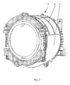
- the shell elements 5 and 6 are in this case partially on the jacket 9 of the plastic liquor container 2, in this example on the outside, attached, which are preferably present in the lower region of the plastic liquor container 2, as shown in the FIG. 2 will be shown.
- the insulation 4 according to the invention consisting of the adjacent vacuum-coated shell elements 5 and 6, isolates the areas where primarily the liquor liquid is located.
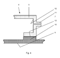
- the thermal insulation 4 in this case preferably consists of two shell elements 5 and 6, which form the tub wall 10, as in particular in the FIG. 4 is shown.
- the inner wall of the insulation 4 forms the tub wall 10 itself, the shell elements 5 and 6 here form the outer wall.
- the shell elements 5 and 6 each have a section U-shaped wall 12, wherein the free leg of the U-shaped wall 12 forms an adhesive surface 13 for the tub wall 10.
- the outer shell elements 5 and 6 are connected to the inner tub wall 10 by gluing, welding and / or vibration welding.
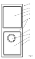
- FIG. 3 are the two shell elements 5 and 6 shown again in the settlement, which are surrounded by an edge 14, from which quasi the shell walls 15 are shown deep drawn.
- at least one opening 16 may be present on one of the shell elements 5 and 6, which is intended in particular for the outlet of the tub 2.
Landscapes
- Engineering & Computer Science (AREA)
- Textile Engineering (AREA)
- Main Body Construction Of Washing Machines And Laundry Dryers (AREA)
- Detail Structures Of Washing Machines And Dryers (AREA)
- Treatment Of Fiber Materials (AREA)
Abstract
Description
- Die Erfindung betrifft eine Wäschebehandlungsmaschine insbesondere Waschmaschine mit einer in einem Kunststofflaugenbehälter drehbar gelagerten Trommel, wobei der Kunststofflaugenbehälter mit einer thermischen Isolation versehen ist.
- Kunststofflaugenbehälter haben gegenüber Stahllaugenbehältern den Nachteil, dass die Wärmekapazität bezogen auf die Oberfläche deutlich größer ist, als beim Stahllaugenbehälter. Der zweite Nachteil ist die ebenfalls deutlich stärkere Wärmeabstrahlung. Diese Nachteile lassen sich positiv beeinflussen, in dem man den Kunststofflaugenbehälter auf der Außenseite mit einer Isolierung versieht.
- So ist beispielsweise aus der
DE 101 60 788 A1 ein Laugenbehälter bekannt, dessen Isolierschicht auf der Innenwand des Laugenbehälters angebracht ist. Dabei wird mit der Isolierschicht, die dünnwandig ausgebildet ist, die gesamte Innenfläche des Laugenbehälters von der Isolierschicht abgedeckt. Andere Lösungen sind beispielsweise aus der
DE 43 32 684 A1 bekannt, wobei die dort beschriebene Ausführungsform einen Laugenbehälterbottich aufweist, dessen Wand hohl ausgebildet ist, wobei insbesondere der Hohlraum wiederum mit einer Isolierung versehen ist. Andere Möglichkeiten sind aus der
DE 86 13 673 U1 sowie aus derWO 2004/005604 A1 bekannt, die ebenfalls Laugenbehälter zeigen, bei denen jedoch die Isolierschicht außen auf der Ummantelung des Laugenbehälters angebracht ist. - Als nachteilig bei all diesen bekannten thermischen Isolationen wird es angesehen, dass sie einerseits aufwendig am Behälter integriert sind, wobei sie andererseits hinsichtlich ihrer Anbringung am Mantel nicht die hinreichende Effizienz aufweisen.
- Der Erfindung stellt sich somit das Problem mit einfachen konstruktiven Mitteln einen Kunststofflaugenbehälter mit einer verbesserten thermischen Isolation zu versehen, die geeignet ist, den Energieverlust wirkungsvoll zu reduzieren.
- Erfindungsgemäß wird dieses Problem mit einer Wäschebehandlungsmaschine mit den Merkmalen des Patentanspruchs 1 gelöst. Vorteilhafte Ausgestaltungen und Weiterbildungen der Erfindung ergeben sich aus den nachfolgenden Unteransprüchen.
- Die mit der Erfindung erreichbaren Vorteile bestehen darin, dass die vorgeschlagene thermische Isolierung in Form von vakuumierten Hohlraumflächen eine einfache und konstruktiv leichte Anbindung an den Kunststofflaugenbehälter ermöglicht. Hinzu kommen ein verbessertes akustisches Verhalten des Laugenbehälters, eine verbesserte Waschwirkung durch kürzere Aufheizzeiten, wobei weniger Energieverbrauch daraus resultiert.
- Erfindungsgemäß besteht hierbei die Isolation aus Schalenelementen, die außenseitig am Kunststofflaugenbehälter angebracht sind und hier die isolierenden Hohlräume bilden, die zur Isolation vakuumiert sind. Die thermische Isolierung ist besonders wirkungsvoll, wenn ein sogenanntes Hochvakuum im Bereich von 10 -3 hPA bis 10 -7 hPA verwendet wird. Die Schalenelemente sind dabei bereichsweise am Mantel des Laugenbehälters positioniert und hier vorzugsweise im unteren Bereich des Laugenbehälters, bezogen auf die betriebsgemäße Aufstellung der Maschine. Somit wird insbesondere in dem Bereich, wo sich auch die erwärmte Lauge befindet, die Hauptisolation vorgenommen. Die thermische Isolation besteht aus zwei Schalenelementen. Die Schalenelemente bilden vorzugsweise die Laugenbehälteraußenwand, wobei die Innenwand des Hohlraums die Laugenbehälterwand bildet. Im Bereich der Stirnseiten der Schalenelemente sind hohle Stutzen vorgesehen zur Vakuumierung des Schalenhohlraums. Auf diese Weise ist es möglich beispielsweise Tiefziehteile aus Kunststoff zu verwenden, die lediglich noch um den Mantel des Laugenbehälters angelegt werden müssen. Um eine dichte Einbindung dieses Tiefziehteils an dem Laugenbehältermantel zu ermöglichen, weisen die Schalenelemente eine U-förmig ausgebildete umlaufende Wand auf, wobei der freie Schenkel der U-förmigen Wand eine Haftfläche für die Laugenbehälterwand bildet.
- Dabei ist wenigstens eines der Schalenelemente mit einem den Hohlraum durchsetzten Durchbruch versehen, der den Auslauf des Laugenbehälters bildet. In diesem Bereich kann somit der Ablauf zum Abpumpen integriert werden. Nach einer besonders vorteilhaften Ausgestaltung der Erfindung bestehen die Schalenelemente hier aus einem Polypropylen-Glasfaser-Material, womit besonders dünnwandige Schalenelemente, die etwa eine Stärke im Bereich von 1,5 bis 2,5 mm, vorzugsweise 2 mm, hergestellt werden können.
- In einer weiteren Ausführung ist der Hohlraum mit einem Faserfliesmaterial gefüllt. Dadurch reicht es aus, dass in den Hohlräumen mit einem geringeren Vakuum, einem sogenannten Niedervakuum im Bereich eines Drucks von 1 hPA bis 10 -3 hPA, eine gute thermische Isolation erreicht wird.
- In einer zweckmäßigen Weiterbildung ist der Hohlraum mittels des Stutzens mit einer Vakuumierungspumpe verbunden, wobei die Pumpe während eines Programmablaufs mittels einer Steuereinrichtung ein,- oder ausschaltbar ist. Mit dieser Anordnung ist es auf einfache Weise möglich, den Hohlraum mit dem Niedervakuum zu versehen. Hierbei ist es zweckmäßig, eine einfache und kostengünstige Flügelzellenpumpe zu verwenden. Das Vakuum wird nur zu den Zeiten programmabhängig erzeugt, wenn es erforderlich ist.
- Ein Ausführungsbeispiel der Erfindung ist in den Zeichnungen rein schematisch dargestellt und wird nachfolgend näher beschrieben. Es zeigt:
- Figur 1
- eine geschnittene Seitenansicht einer Waschmaschine;
- Figur 2
- eine perspektivische Darstellung des Kunststofflaugenbehälters mit am Mantel angesetzter Isolation;
- Figur 3
- eine Einzelansicht in Draufsicht der Schalenelemente und
- Figur 4
- eine Detailansicht in geschnittener Ansicht bezüglich der Anbindung des Schalenelementes an dem Kunststofflaugenbehälter in der geschnittenen Ansicht.
- Die
Figur 1 zeigt in der geschnittenen Ansicht eine Wäschebehandlungsmaschine und hier insbesondere eine Waschmaschine 1, mit einer in einem Kunststofflaugenbehälter 2 drehbar gelagerten Trommel 3. Wie insbesondere aus derFigur 2 , aus der perspektivischen Ansicht eines isoliert dargestellten Laugenbehälters 2 zu erkennen ist, ist der Kunststofflaugenbehälter 2 mit einer thermischen Isolierung 4 versehen. Wie sich die thermische Isolierung 4 nun an dem Kunststofflaugenbehälter 2 ergibt, zeigt sich in der Zusammenschau derFiguren 3 und4 . Dabei besteht die Isolation 4 aus Schalenelementen 5 und 6, die außenseitig am Kunststofflaugenbehälter 2 Hohlräume 7 und 8 bilden, wobei die Hohlräume 7 und 8 zur Isolation 4 vakuumiert werden. - Die Schalenelemente 5 und 6 sind hierbei bereichsweise am Mantel 9 des Kunststofflaugenbehälters 2, in diesem Beispiel außenseitig, angebracht, wobei diese vorzugsweise im unteren Bereich des Kunststofflaugenbehälters 2 vorhanden sind, wie dies in der
Figur 2 gezeigt wird. Somit isoliert die erfindungsgemäße Isolation 4, bestehend aus den anliegenden vakuumierten Schalenelementen 5 und 6 den Bereichen, wo sich vornehmlich die Laugenflüssigkeit befindet. Die thermische Isolation 4 besteht hierbei vorzugsweise aus zwei Schalenelementen 5 und 6, die die Laugenbehälterwand 10 bilden, wie dies insbesondere in derFigur 4 dargestellt ist. Dabei bildet insbesondere die Innenwand der Isolation 4 die Laugenbehälterwand 10 selbst, wobei die Schalenelemente 5 und 6 hier die Außenwand bilden. Wie insbesondere aus derFigur 4 zu erkennen ist, sind im Bereich der Stirnseiten der Schalenelemente 5 und 6 hohle bzw. röhrenartige Stutzen 11 vorgesehen zur Vakuumierung der Hohlräume 7 und 8. Nach der Vakuumierung werden die Stutzen 11 verschlossen, beispielsweise durch Verkleben und/ oder Verschweißen. Die Schalenelemente 5 und 6 weisen jeweils eine im Schnitt U-förmig ausgebildete Wand 12 auf, wobei der freie Schenkel der U-förmigen Wand 12 eine Haftfläche 13 für die Laugenbehälterwand 10 bildet. Die äußeren Schalenelemente 5 und 6 werden mittels Verklebung, Schweißen und/oder Vibrationsschweißen mit der inneren Laugenbehälterwand 10 verbunden. - In der
Figur 3 sind die beiden Schalenelemente 5 und 6 nochmals in der Abwicklung dargestellt, wobei diese von einem Rand 14 umgeben sind, aus dem quasi die Schalenwände 15 tiefgezogen dargestellt sind. Dabei kann wenigstens ein Durchbruch 16 an einem der Schalenelemente 5 und 6 vorhanden sein, der insbesondere für den Auslauf des Laugenbehälters 2 bestimmt ist. Die Schalenelemente 5 und 6 als solches sind hierbei vorzugsweise aus einem PP-Glasfaser-Material (PP=Polypropylen) gefertigt. Mit diesem Material ist eine gegenüber den vorbekannten Kunststofflaugenbehältern dünnwandige Ausführung möglich, so dass die Wandstärke im Bereich zwischen 1,5 bis 2,5 mm, vorteilhafterweise etwa 2mm, liegt.
Claims (11)
- Wäschebehandlungsmaschine insbesondere Waschmaschine (1) mit einer in einem Kunststofflaugenbehälter (2) drehbar gelagerten Trommel (3), wobei der Kunststofflaugenbehälter (2) mit einer thermischen Isolation (4) versehen ist,
dadurch gekennzeichnet,
dass die Isolation (4) aus Schalenelementen (5, 6) besteht, die außenseitig am Kunststofflaugenbehälter (2) Hohlräume (7, 8) bilden, wobei die Hohlräume (7, 8) zur Isolation (4) vakuumiert sind. - Wäschebehandlungsmaschine nach Anspruch 1,
dadurch gekennzeichnet,
dass die Schalenelemente (5, 6) bereichsweise am Mantel (9) und im unteren Bereich des Kunststofflaugenbehälters (2), bezogen auf die betriebsgemäße Position des Kunststofflaugenbehälters (2), positioniert sind. - Wäschebehandlungsmaschine nach Anspruch 1 oder 2,
dadurch gekennzeichnet,
dass die thermische Isolation (4) vorzugsweise aus zwei Schalenelementen (5, 6) besteht. - Wäschebehandlungsmaschine nach einem der Ansprüche 1 bis 3,
dadurch gekennzeichnet,
dass die Schalenelemente (5, 6) die Kunststofflaugenbehälteraußenwand bilden, wobei die Innenwand des Hohlraumes (7, 8) die Kunststofflaugenbehälterwand (10) bildet. - Wäschebehandlungsmaschine nach Anspruch 4,
dadurch gekennzeichnet,
dass die Schalenelemente (5, 6) mittels Verklebung, Schweißen, Spiegelschweißen und/oder Vibrationsschweißen an der Behälterwand (10) befestigt sind. - Wäschebehandlungsmaschine nach einem der Ansprüche 1 bis 4,
dadurch gekennzeichnet,
dass im Bereich der Stirnseiten der Schalenelemente (5, 6) Stutzen (11) vorgesehen sind zur Vakuumierung des Schalenhohlraumes (7, 8). - Wäschebehandlungsmaschine nach einem der Ansprüche 1 bis 6,
dadurch gekennzeichnet,
dass die Schalenelemente (5, 6) eine U-förmig ausgebildete umlaufende Wand (12) aufweisen, wobei der freie Schenkel der U-förmigen Wand eine Haftfläche (13) für die Kunststofflaugenbehälterwand (10) bildet. - Wäschebehandlungsmaschine nach einem der Ansprüche 1 bis 7,
dadurch gekennzeichnet,
dass wenigstens eines der Schalenelemente (5, 6) mit einem den Hohlraum durchsetztem Durchbruch (16) versehen ist, der den Auslauf des Kunststofflaugenbehälters (2) bildet. - Wäschebehandlungsmaschine nach einem der Ansprüche 1 bis 8,
dadurch gekennzeichnet,
dass die Schalenelemente (5, 6) und/oder die Laugenbehälterwand (10) aus einem PP-Glasfaser-Material bestehen. - Wäschebehandlungsmaschine nach einem der Ansprüche 1 bis 6,
dadurch gekennzeichnet,
dass der Hohlraum mit einem Faservliesmaterial gefüllt ist. - Wäschebehandlungsmaschine nach einem der Ansprüche 1 bis 10,
dadurch gekennzeichnet,
dass der Hohlraum mittels des Stutzens mit einer Vakuumierungspumpe verbunden ist, wobei die Pumpe während eines Programmablaufs mittels einer Steuereinrichtung ein,- oder ausschaltbar ist.
Applications Claiming Priority (1)
| Application Number | Priority Date | Filing Date | Title |
|---|---|---|---|
| DE102008056555A DE102008056555B3 (de) | 2008-11-10 | 2008-11-10 | Wäschebehandlungsmaschine insbesondere Waschmaschine mit isoliertem Kunststofflaugenbehälter |
Publications (2)
| Publication Number | Publication Date |
|---|---|
| EP2184393A1 true EP2184393A1 (de) | 2010-05-12 |
| EP2184393B1 EP2184393B1 (de) | 2012-01-18 |
Family
ID=41269054
Family Applications (1)
| Application Number | Title | Priority Date | Filing Date |
|---|---|---|---|
| EP09401028A Not-in-force EP2184393B1 (de) | 2008-11-10 | 2009-11-02 | Wäschebehandlungsmaschine insbesondere Waschmaschine mit wärmeisoliertem Kunststofflaugenbehälter |
Country Status (4)
| Country | Link |
|---|---|
| EP (1) | EP2184393B1 (de) |
| AT (1) | ATE541977T1 (de) |
| DE (1) | DE102008056555B3 (de) |
| ES (1) | ES2376970T3 (de) |
Cited By (1)
| Publication number | Priority date | Publication date | Assignee | Title |
|---|---|---|---|---|
| WO2014012786A1 (de) | 2012-07-19 | 2014-01-23 | BSH Bosch und Siemens Hausgeräte GmbH | Wäschetrockner mit lagerschild mit thermischer isolierung sowie hierfür geeignetes lagerschild |
Families Citing this family (3)
| Publication number | Priority date | Publication date | Assignee | Title |
|---|---|---|---|---|
| EP2392718B1 (de) * | 2010-06-01 | 2015-08-12 | Electrolux Home Products Corporation N.V. | Waschmaschine |
| EP2551396B1 (de) | 2011-07-27 | 2020-02-05 | Electrolux Home Products Corporation N.V. | Waschmaschine |
| DE102015102932A1 (de) * | 2015-03-02 | 2016-09-08 | Miele & Cie. Kg | Laugenbehälter für eine Waschmaschine |
Citations (8)
| Publication number | Priority date | Publication date | Assignee | Title |
|---|---|---|---|---|
| US2154354A (en) * | 1937-07-01 | 1939-04-11 | Ranson Russell | Regulator |
| DE8613673U1 (de) | 1986-05-21 | 1986-07-03 | Richter, Rudolf, 8300 Landshut | Thermoisolierter Laugenbottich in Waschvollautomaten |
| WO1990009547A1 (en) * | 1989-02-13 | 1990-08-23 | Nelson Thomas E | Thermal insulation jacket |
| DE4332684A1 (de) | 1993-09-25 | 1995-03-30 | Licentia Gmbh | Waschmaschine |
| DE29518110U1 (de) * | 1995-11-15 | 1996-11-28 | Achenbach GmbH & Co. KG, 57548 Kirchen | Wärmeisolierende Körper-Ummantelung |
| WO2001039570A1 (de) | 1999-12-01 | 2001-06-07 | BSH Bosch und Siemens Hausgeräte GmbH | Wärmeisolierende wandung |
| DE10160788A1 (de) | 2001-12-11 | 2003-06-26 | Bsh Bosch Siemens Hausgeraete | Laugenbehälter mit einer Isolierschicht für wasserführende Haushaltgeräte |
| WO2004005604A1 (en) | 2002-07-09 | 2004-01-15 | Owens Corning | Acoustical laundry tub blanket |
-
2008
- 2008-11-10 DE DE102008056555A patent/DE102008056555B3/de not_active Expired - Fee Related
-
2009
- 2009-11-02 ES ES09401028T patent/ES2376970T3/es active Active
- 2009-11-02 AT AT09401028T patent/ATE541977T1/de active
- 2009-11-02 EP EP09401028A patent/EP2184393B1/de not_active Not-in-force
Patent Citations (8)
| Publication number | Priority date | Publication date | Assignee | Title |
|---|---|---|---|---|
| US2154354A (en) * | 1937-07-01 | 1939-04-11 | Ranson Russell | Regulator |
| DE8613673U1 (de) | 1986-05-21 | 1986-07-03 | Richter, Rudolf, 8300 Landshut | Thermoisolierter Laugenbottich in Waschvollautomaten |
| WO1990009547A1 (en) * | 1989-02-13 | 1990-08-23 | Nelson Thomas E | Thermal insulation jacket |
| DE4332684A1 (de) | 1993-09-25 | 1995-03-30 | Licentia Gmbh | Waschmaschine |
| DE29518110U1 (de) * | 1995-11-15 | 1996-11-28 | Achenbach GmbH & Co. KG, 57548 Kirchen | Wärmeisolierende Körper-Ummantelung |
| WO2001039570A1 (de) | 1999-12-01 | 2001-06-07 | BSH Bosch und Siemens Hausgeräte GmbH | Wärmeisolierende wandung |
| DE10160788A1 (de) | 2001-12-11 | 2003-06-26 | Bsh Bosch Siemens Hausgeraete | Laugenbehälter mit einer Isolierschicht für wasserführende Haushaltgeräte |
| WO2004005604A1 (en) | 2002-07-09 | 2004-01-15 | Owens Corning | Acoustical laundry tub blanket |
Cited By (2)
| Publication number | Priority date | Publication date | Assignee | Title |
|---|---|---|---|---|
| WO2014012786A1 (de) | 2012-07-19 | 2014-01-23 | BSH Bosch und Siemens Hausgeräte GmbH | Wäschetrockner mit lagerschild mit thermischer isolierung sowie hierfür geeignetes lagerschild |
| DE102012212739A1 (de) | 2012-07-19 | 2014-01-23 | BSH Bosch und Siemens Hausgeräte GmbH | Wäschetrockner mit Lagerschild mit thermischer Isolierung sowie hierfür geeignetes Lagerschild |
Also Published As
| Publication number | Publication date |
|---|---|
| ES2376970T3 (es) | 2012-03-21 |
| DE102008056555B3 (de) | 2009-12-10 |
| ATE541977T1 (de) | 2012-02-15 |
| EP2184393B1 (de) | 2012-01-18 |
Similar Documents
| Publication | Publication Date | Title |
|---|---|---|
| DE102008046835B4 (de) | Trommelwaschmaschine | |
| EP1833353B1 (de) | Geschirrspülmaschine mit einer sorptionstrockenvorrichtung | |
| EP1733675B1 (de) | Geschirrspülmaschine mit einem Spülbehälter, der durch eine Tür verschliessbar ist, und Verfahren zur Durchführung eines Spülprogramms in einer solchen Geschirrspülmaschine | |
| DE102007056921A1 (de) | Wasserführendes Haushaltsgerät mit einer Wasserweiche | |
| EP2184393B1 (de) | Wäschebehandlungsmaschine insbesondere Waschmaschine mit wärmeisoliertem Kunststofflaugenbehälter | |
| EP2794978B1 (de) | Einspülanordnung für ein haushaltsgerät zur pflege von wäschestücken sowie haushaltsgerät zur pflege von wäschestücken | |
| DE102007056922A1 (de) | Wasserführendes Hausgerät mit einer Wasserweiche | |
| DE102007057336A1 (de) | Wasserführendes Haushaltsgerät mit einer Wasserweiche | |
| DE102012218549A1 (de) | Einspülanordnung für ein Haushaltsgerät zur Pflege von Wäschestücken sowie Haushaltsgerät zur Pflege von Wäschestücken | |
| DE60010201T2 (de) | Dampfkondensationskammer für eine Geschirrspülmaschine | |
| EP2794981B1 (de) | Haushaltsgerät zur pflege von wäschestücken mit einer einspülschale und einem laugenbehälter | |
| DE60311174T2 (de) | In einer Spüle eingebaute rauscharme Spülmaschine | |
| DE102008026453B4 (de) | Wäschebehandlungsmaschine insbesondere Waschmaschine mit einem Kunststofflaugenbehälter | |
| EP3384822B1 (de) | Geschirrspülmaschine, insbesondere haushaltsgeschirrspülmaschine | |
| EP2359737A2 (de) | Haushaltsgerät mit mindestens einem Aussteifungskörper | |
| DE10160788A1 (de) | Laugenbehälter mit einer Isolierschicht für wasserführende Haushaltgeräte | |
| WO2015028271A1 (de) | Haushaltsgerät mit wegeventil | |
| DE102011081019A1 (de) | Hausgerät, wie Waschmaschine, mit Strömung von Flüssigkeit, wie Waschlauge, an einem Rohrheizkörper | |
| DE102011053950A1 (de) | Waschmaschine mit einem in einem Maschinengehäuse angeordneten Laugenbehälter | |
| EP2407586B1 (de) | Hausgerät mit einer Trommel | |
| DE2152021A1 (de) | Anordnung bei einer Geschirrspuelmaschine | |
| DE2041207A1 (de) | Waschmaschine | |
| DE102011080619A1 (de) | Geschirrspülmaschine mit einer Erwärmungseinrichtung zur Kondensationsflüssigkeitsvermeidung | |
| DE69819068T2 (de) | Geschirrspülmaschine mit einer Flüssigkeitsdosierungsvorrichtung | |
| EP3335616A1 (de) | Haushaltsgeschirrspülmaschine mit wärmepumpenanordnung |
Legal Events
| Date | Code | Title | Description |
|---|---|---|---|
| PUAI | Public reference made under article 153(3) epc to a published international application that has entered the european phase |
Free format text: ORIGINAL CODE: 0009012 |
|
| AK | Designated contracting states |
Kind code of ref document: A1 Designated state(s): AT BE BG CH CY CZ DE DK EE ES FI FR GB GR HR HU IE IS IT LI LT LU LV MC MK MT NL NO PL PT RO SE SI SK SM TR |
|
| AX | Request for extension of the european patent |
Extension state: AL BA RS |
|
| 17P | Request for examination filed |
Effective date: 20101009 |
|
| GRAP | Despatch of communication of intention to grant a patent |
Free format text: ORIGINAL CODE: EPIDOSNIGR1 |
|
| RIC1 | Information provided on ipc code assigned before grant |
Ipc: A47L 15/42 20060101ALI20110829BHEP Ipc: D06F 37/26 20060101AFI20110829BHEP |
|
| GRAS | Grant fee paid |
Free format text: ORIGINAL CODE: EPIDOSNIGR3 |
|
| GRAA | (expected) grant |
Free format text: ORIGINAL CODE: 0009210 |
|
| AK | Designated contracting states |
Kind code of ref document: B1 Designated state(s): AT BE BG CH CY CZ DE DK EE ES FI FR GB GR HR HU IE IS IT LI LT LU LV MC MK MT NL NO PL PT RO SE SI SK SM TR |
|
| REG | Reference to a national code |
Ref country code: GB Ref legal event code: FG4D Free format text: NOT ENGLISH |
|
| REG | Reference to a national code |
Ref country code: CH Ref legal event code: EP |
|
| REG | Reference to a national code |
Ref country code: DE Ref legal event code: R084 Ref document number: 502009002482 Country of ref document: DE |
|
| REG | Reference to a national code |
Ref country code: IE Ref legal event code: FG4D Free format text: LANGUAGE OF EP DOCUMENT: GERMAN Ref country code: AT Ref legal event code: REF Ref document number: 541977 Country of ref document: AT Kind code of ref document: T Effective date: 20120215 |
|
| REG | Reference to a national code |
Ref country code: ES Ref legal event code: GC2A Effective date: 20120208 |
|
| REG | Reference to a national code |
Ref country code: GB Ref legal event code: 746 Effective date: 20120130 |
|
| REG | Reference to a national code |
Ref country code: ES Ref legal event code: FG2A Ref document number: 2376970 Country of ref document: ES Kind code of ref document: T3 Effective date: 20120321 |
|
| REG | Reference to a national code |
Ref country code: DE Ref legal event code: R096 Ref document number: 502009002482 Country of ref document: DE Effective date: 20120322 |
|
| REG | Reference to a national code |
Ref country code: DE Ref legal event code: R084 Ref document number: 502009002482 Country of ref document: DE Effective date: 20120210 |
|
| REG | Reference to a national code |
Ref country code: NL Ref legal event code: VDEP Effective date: 20120118 |
|
| LTIE | Lt: invalidation of european patent or patent extension |
Effective date: 20120118 |
|
| PG25 | Lapsed in a contracting state [announced via postgrant information from national office to epo] |
Ref country code: NL Free format text: LAPSE BECAUSE OF FAILURE TO SUBMIT A TRANSLATION OF THE DESCRIPTION OR TO PAY THE FEE WITHIN THE PRESCRIBED TIME-LIMIT Effective date: 20120118 Ref country code: IS Free format text: LAPSE BECAUSE OF FAILURE TO SUBMIT A TRANSLATION OF THE DESCRIPTION OR TO PAY THE FEE WITHIN THE PRESCRIBED TIME-LIMIT Effective date: 20120518 Ref country code: BG Free format text: LAPSE BECAUSE OF FAILURE TO SUBMIT A TRANSLATION OF THE DESCRIPTION OR TO PAY THE FEE WITHIN THE PRESCRIBED TIME-LIMIT Effective date: 20120418 Ref country code: NO Free format text: LAPSE BECAUSE OF FAILURE TO SUBMIT A TRANSLATION OF THE DESCRIPTION OR TO PAY THE FEE WITHIN THE PRESCRIBED TIME-LIMIT Effective date: 20120418 Ref country code: HR Free format text: LAPSE BECAUSE OF FAILURE TO SUBMIT A TRANSLATION OF THE DESCRIPTION OR TO PAY THE FEE WITHIN THE PRESCRIBED TIME-LIMIT Effective date: 20120118 Ref country code: LT Free format text: LAPSE BECAUSE OF FAILURE TO SUBMIT A TRANSLATION OF THE DESCRIPTION OR TO PAY THE FEE WITHIN THE PRESCRIBED TIME-LIMIT Effective date: 20120118 |
|
| REG | Reference to a national code |
Ref country code: IE Ref legal event code: FD4D |
|
| PG25 | Lapsed in a contracting state [announced via postgrant information from national office to epo] |
Ref country code: LV Free format text: LAPSE BECAUSE OF FAILURE TO SUBMIT A TRANSLATION OF THE DESCRIPTION OR TO PAY THE FEE WITHIN THE PRESCRIBED TIME-LIMIT Effective date: 20120118 Ref country code: GR Free format text: LAPSE BECAUSE OF FAILURE TO SUBMIT A TRANSLATION OF THE DESCRIPTION OR TO PAY THE FEE WITHIN THE PRESCRIBED TIME-LIMIT Effective date: 20120419 Ref country code: PT Free format text: LAPSE BECAUSE OF FAILURE TO SUBMIT A TRANSLATION OF THE DESCRIPTION OR TO PAY THE FEE WITHIN THE PRESCRIBED TIME-LIMIT Effective date: 20120518 Ref country code: FI Free format text: LAPSE BECAUSE OF FAILURE TO SUBMIT A TRANSLATION OF THE DESCRIPTION OR TO PAY THE FEE WITHIN THE PRESCRIBED TIME-LIMIT Effective date: 20120118 Ref country code: PL Free format text: LAPSE BECAUSE OF FAILURE TO SUBMIT A TRANSLATION OF THE DESCRIPTION OR TO PAY THE FEE WITHIN THE PRESCRIBED TIME-LIMIT Effective date: 20120118 |
|
| PG25 | Lapsed in a contracting state [announced via postgrant information from national office to epo] |
Ref country code: CY Free format text: LAPSE BECAUSE OF FAILURE TO SUBMIT A TRANSLATION OF THE DESCRIPTION OR TO PAY THE FEE WITHIN THE PRESCRIBED TIME-LIMIT Effective date: 20120118 |
|
| PG25 | Lapsed in a contracting state [announced via postgrant information from national office to epo] |
Ref country code: RO Free format text: LAPSE BECAUSE OF FAILURE TO SUBMIT A TRANSLATION OF THE DESCRIPTION OR TO PAY THE FEE WITHIN THE PRESCRIBED TIME-LIMIT Effective date: 20120118 Ref country code: CZ Free format text: LAPSE BECAUSE OF FAILURE TO SUBMIT A TRANSLATION OF THE DESCRIPTION OR TO PAY THE FEE WITHIN THE PRESCRIBED TIME-LIMIT Effective date: 20120118 Ref country code: DK Free format text: LAPSE BECAUSE OF FAILURE TO SUBMIT A TRANSLATION OF THE DESCRIPTION OR TO PAY THE FEE WITHIN THE PRESCRIBED TIME-LIMIT Effective date: 20120118 Ref country code: EE Free format text: LAPSE BECAUSE OF FAILURE TO SUBMIT A TRANSLATION OF THE DESCRIPTION OR TO PAY THE FEE WITHIN THE PRESCRIBED TIME-LIMIT Effective date: 20120118 Ref country code: SE Free format text: LAPSE BECAUSE OF FAILURE TO SUBMIT A TRANSLATION OF THE DESCRIPTION OR TO PAY THE FEE WITHIN THE PRESCRIBED TIME-LIMIT Effective date: 20120118 Ref country code: SI Free format text: LAPSE BECAUSE OF FAILURE TO SUBMIT A TRANSLATION OF THE DESCRIPTION OR TO PAY THE FEE WITHIN THE PRESCRIBED TIME-LIMIT Effective date: 20120118 Ref country code: IE Free format text: LAPSE BECAUSE OF FAILURE TO SUBMIT A TRANSLATION OF THE DESCRIPTION OR TO PAY THE FEE WITHIN THE PRESCRIBED TIME-LIMIT Effective date: 20120118 |
|
| PLBE | No opposition filed within time limit |
Free format text: ORIGINAL CODE: 0009261 |
|
| STAA | Information on the status of an ep patent application or granted ep patent |
Free format text: STATUS: NO OPPOSITION FILED WITHIN TIME LIMIT |
|
| PG25 | Lapsed in a contracting state [announced via postgrant information from national office to epo] |
Ref country code: SK Free format text: LAPSE BECAUSE OF FAILURE TO SUBMIT A TRANSLATION OF THE DESCRIPTION OR TO PAY THE FEE WITHIN THE PRESCRIBED TIME-LIMIT Effective date: 20120118 |
|
| 26N | No opposition filed |
Effective date: 20121019 |
|
| REG | Reference to a national code |
Ref country code: DE Ref legal event code: R097 Ref document number: 502009002482 Country of ref document: DE Effective date: 20121019 |
|
| BERE | Be: lapsed |
Owner name: MIELE & CIE. K.G. Effective date: 20121130 |
|
| PG25 | Lapsed in a contracting state [announced via postgrant information from national office to epo] |
Ref country code: BE Free format text: LAPSE BECAUSE OF NON-PAYMENT OF DUE FEES Effective date: 20121130 |
|
| PG25 | Lapsed in a contracting state [announced via postgrant information from national office to epo] |
Ref country code: MT Free format text: LAPSE BECAUSE OF FAILURE TO SUBMIT A TRANSLATION OF THE DESCRIPTION OR TO PAY THE FEE WITHIN THE PRESCRIBED TIME-LIMIT Effective date: 20120118 |
|
| PGFP | Annual fee paid to national office [announced via postgrant information from national office to epo] |
Ref country code: GB Payment date: 20131122 Year of fee payment: 5 Ref country code: DE Payment date: 20131119 Year of fee payment: 5 Ref country code: FR Payment date: 20131119 Year of fee payment: 5 |
|
| PGFP | Annual fee paid to national office [announced via postgrant information from national office to epo] |
Ref country code: IT Payment date: 20131126 Year of fee payment: 5 Ref country code: ES Payment date: 20131120 Year of fee payment: 5 |
|
| PG25 | Lapsed in a contracting state [announced via postgrant information from national office to epo] |
Ref country code: TR Free format text: LAPSE BECAUSE OF FAILURE TO SUBMIT A TRANSLATION OF THE DESCRIPTION OR TO PAY THE FEE WITHIN THE PRESCRIBED TIME-LIMIT Effective date: 20120118 Ref country code: MC Free format text: LAPSE BECAUSE OF NON-PAYMENT OF DUE FEES Effective date: 20121130 |
|
| PG25 | Lapsed in a contracting state [announced via postgrant information from national office to epo] |
Ref country code: LU Free format text: LAPSE BECAUSE OF NON-PAYMENT OF DUE FEES Effective date: 20121102 Ref country code: SM Free format text: LAPSE BECAUSE OF FAILURE TO SUBMIT A TRANSLATION OF THE DESCRIPTION OR TO PAY THE FEE WITHIN THE PRESCRIBED TIME-LIMIT Effective date: 20120118 |
|
| REG | Reference to a national code |
Ref country code: CH Ref legal event code: PL |
|
| PG25 | Lapsed in a contracting state [announced via postgrant information from national office to epo] |
Ref country code: LI Free format text: LAPSE BECAUSE OF NON-PAYMENT OF DUE FEES Effective date: 20131130 Ref country code: HU Free format text: LAPSE BECAUSE OF FAILURE TO SUBMIT A TRANSLATION OF THE DESCRIPTION OR TO PAY THE FEE WITHIN THE PRESCRIBED TIME-LIMIT Effective date: 20091102 Ref country code: CH Free format text: LAPSE BECAUSE OF NON-PAYMENT OF DUE FEES Effective date: 20131130 |
|
| REG | Reference to a national code |
Ref country code: DE Ref legal event code: R119 Ref document number: 502009002482 Country of ref document: DE |
|
| GBPC | Gb: european patent ceased through non-payment of renewal fee |
Effective date: 20141102 |
|
| PG25 | Lapsed in a contracting state [announced via postgrant information from national office to epo] |
Ref country code: MK Free format text: LAPSE BECAUSE OF FAILURE TO SUBMIT A TRANSLATION OF THE DESCRIPTION OR TO PAY THE FEE WITHIN THE PRESCRIBED TIME-LIMIT Effective date: 20120118 |
|
| REG | Reference to a national code |
Ref country code: FR Ref legal event code: ST Effective date: 20150731 |
|
| PG25 | Lapsed in a contracting state [announced via postgrant information from national office to epo] |
Ref country code: DE Free format text: LAPSE BECAUSE OF NON-PAYMENT OF DUE FEES Effective date: 20150602 Ref country code: GB Free format text: LAPSE BECAUSE OF NON-PAYMENT OF DUE FEES Effective date: 20141102 |
|
| PG25 | Lapsed in a contracting state [announced via postgrant information from national office to epo] |
Ref country code: FR Free format text: LAPSE BECAUSE OF NON-PAYMENT OF DUE FEES Effective date: 20141201 |
|
| REG | Reference to a national code |
Ref country code: ES Ref legal event code: FD2A Effective date: 20151229 |
|
| PG25 | Lapsed in a contracting state [announced via postgrant information from national office to epo] |
Ref country code: IT Free format text: LAPSE BECAUSE OF NON-PAYMENT OF DUE FEES Effective date: 20141102 |
|
| REG | Reference to a national code |
Ref country code: AT Ref legal event code: MM01 Ref document number: 541977 Country of ref document: AT Kind code of ref document: T Effective date: 20141102 |
|
| PG25 | Lapsed in a contracting state [announced via postgrant information from national office to epo] |
Ref country code: AT Free format text: LAPSE BECAUSE OF NON-PAYMENT OF DUE FEES Effective date: 20141102 Ref country code: ES Free format text: LAPSE BECAUSE OF NON-PAYMENT OF DUE FEES Effective date: 20141103 |
|
| P01 | Opt-out of the competence of the unified patent court (upc) registered |
Effective date: 20230529 |