EP2180258B1 - Dispositif de cuisson - Google Patents
Dispositif de cuisson Download PDFInfo
- Publication number
- EP2180258B1 EP2180258B1 EP20080790228 EP08790228A EP2180258B1 EP 2180258 B1 EP2180258 B1 EP 2180258B1 EP 20080790228 EP20080790228 EP 20080790228 EP 08790228 A EP08790228 A EP 08790228A EP 2180258 B1 EP2180258 B1 EP 2180258B1
- Authority
- EP
- European Patent Office
- Prior art keywords
- switch
- mode
- heating
- control
- cooking device
- Prior art date
- Legal status (The legal status is an assumption and is not a legal conclusion. Google has not performed a legal analysis and makes no representation as to the accuracy of the status listed.)
- Active
Links
- 238000010411 cooking Methods 0.000 title claims description 89
- 238000010438 heat treatment Methods 0.000 claims description 116
- 230000006870 function Effects 0.000 description 41
- 238000000034 method Methods 0.000 description 8
- 238000010586 diagram Methods 0.000 description 4
- 230000006698 induction Effects 0.000 description 4
- 241000209094 Oryza Species 0.000 description 2
- 235000007164 Oryza sativa Nutrition 0.000 description 2
- 238000009835 boiling Methods 0.000 description 2
- 230000000694 effects Effects 0.000 description 2
- 239000004973 liquid crystal related substance Substances 0.000 description 2
- 235000009566 rice Nutrition 0.000 description 2
- XLYOFNOQVPJJNP-UHFFFAOYSA-N water Substances O XLYOFNOQVPJJNP-UHFFFAOYSA-N 0.000 description 2
- 239000000919 ceramic Substances 0.000 description 1
- 229910052736 halogen Inorganic materials 0.000 description 1
- 150000002367 halogens Chemical class 0.000 description 1
- 230000007704 transition Effects 0.000 description 1
Images


Classifications
-
- H—ELECTRICITY
- H05—ELECTRIC TECHNIQUES NOT OTHERWISE PROVIDED FOR
- H05B—ELECTRIC HEATING; ELECTRIC LIGHT SOURCES NOT OTHERWISE PROVIDED FOR; CIRCUIT ARRANGEMENTS FOR ELECTRIC LIGHT SOURCES, IN GENERAL
- H05B6/00—Heating by electric, magnetic or electromagnetic fields
- H05B6/02—Induction heating
- H05B6/06—Control, e.g. of temperature, of power
- H05B6/062—Control, e.g. of temperature, of power for cooking plates or the like
-
- F—MECHANICAL ENGINEERING; LIGHTING; HEATING; WEAPONS; BLASTING
- F24—HEATING; RANGES; VENTILATING
- F24C—DOMESTIC STOVES OR RANGES ; DETAILS OF DOMESTIC STOVES OR RANGES, OF GENERAL APPLICATION
- F24C7/00—Stoves or ranges heated by electric energy
- F24C7/08—Arrangement or mounting of control or safety devices
- F24C7/082—Arrangement or mounting of control or safety devices on ranges, e.g. control panels, illumination
Definitions
- the present invention relates to a cooking device for heating a cooking container.
- the present invention relates to a cooking device including a plurality of operation switches to control cooking.
- a cooking device which has an operation unit provided on a front surface of a main body serving as shell, and a cooking device which has an operation unit provided on a top plate for placing the cooking container. Moreover, there is provided a cooking device which has the operation units provided on both the top plate and the front surface of the main body (see e.g. Patent document) JP-A-2003-208972 .
- the operation unit is made up of a plurality of switches, each of which is assigned with a predetermined function.
- Prior art document JP 2005 308 266 A discloses a cooking device and a cooking method using the cooking device, wherein a control or operation panel is provided having a plurality of switching elements which can be operated by the user.
- the plural switching elements are provided with labels so that the user can consider the respective function underlying each of the switching elements.
- the operation panel is provided on the cooking device and has a cooking type selection part for selecting one of a plurality of cooking types. Upon selection of a specific cooking type further information on the selected cooking type is displayed to the user on a display part, such as a cooking temperature fitting the selected cooking type and a cooking time. Parameters of the selected cooking type are displayed.
- the number of functions provided in the cooking device is increasing in recent years. For example, functions such as a timer function for setting cooking time and an automatic cooking function for automatically performing water boiling, rice cooking, and the like are newly provided to the cooking device. Each of such functions is assigned to the switch, and thus the number of switches increases as the number of functions increases. The operation becomes complicating if the number of switches is increased with an increase in the number of functions of the device, and a target operation becomes difficult to perform for a user who does not require all the functions. Thus, there arises a problem in that an operating error of the user increases. Such a problem is especially serious to the user who does not require many functions or who cannot make sufficient use of the functions.
- a cooking device includes: a main body serving as shell; a top plate provided on an upper surface of the main body; a heating unit operable to heat an object to be heated placed on the upper surface of the main body; a plurality of control mode switches, each of which is operable to select one of a plurality of control modes for controlling a heating operation of the heating unit; at least one setting switch operable to select a set value in each control mode; a heating control unit operable to control the heating unit based on the control mode and the set value inputted through the control mode switch and the setting switch; and a selection switch operable to select one operation mode from a plurality of operation modes; wherein the operation modes include a first operation mode in which all of the plurality of control modes are set to be selectable and a second operation mode in which only part of the plurality of control modes are set to be selectable; when the first operation m ode is selected by the selection switch, the heating control unit enables all of the control mode switches so that all of the plurality of control modes are
- a cooking device that can respond with a simple switching to both a user who can perform complicating operations and attempts to use a great number of functions, and a user who uses only simple functions and desires easy operation.
- the cooking device may further include a first notifying unit operable to notify distinctively the enabled control mode switch and the enabled setting switch from the disabled control mode switch and the disabled setting switch in the second operation mode.
- a first notifying unit operable to notify distinctively the enabled control mode switch and the enabled setting switch from the disabled control mode switch and the disabled setting switch in the second operation mode.
- the user can thus know which switch is operable.
- the switch itself may be illuminated or non-illuminated to notify the enabled control mode switch and the enabled setting switch, and the disabled control mode switch and the disabled setting switch in a distinguished manner.
- the enabled control mode switch and the enabled setting switch may be arranged adjacent to at least one other enabled control mode switch or enabled setting switch in the second operation mode. The user can thus easily determine the usable control mode switch and the usable setting switch, and the unusable control mode switch and the unusable setting switch.
- the cooking device may further include a second notifying unit operable to notify whether the cooking device is operating in the first operation mode or in the second operation mode; wherein when the disabled control mode switch or setting switch is operated, at least one of the first notifying unit or the second notifying unit may notify that the operated control mode switch or the operated setting switch is disabled.
- the cooking device is configured so that the selection switch is not accepted when the selection switch and one of the control mode switches and the setting switch are simultaneously operated.
- the operation mode is thus not easily changed even when the user touches the selection switch by mistake while operating another switch.
- the selection switch may be a switch which has an electrical contact and is operable to open or close; and the control mode switch and the setting switch may be touch switches of electrostatic capacity type. The operation mode is thus not easily changed even when the user touches the selection switch by mistake while operating another switch.
- the cooking device may further include: a power switch operable to disable all operations in an OFF state of the power switch and to enable at least one switch to be operated in an ON state of the power switch; and a non-volatile memory operable to store the operation mode selected by the selection switch when the power switch is in the ON state; wherein the cooking device may be operate in the stored operation mode when the power switch is turned from off to on.
- a power switch operable to disable all operations in an OFF state of the power switch and to enable at least one switch to be operated in an ON state of the power switch
- a non-volatile memory operable to store the operation mode selected by the selection switch when the power switch is in the ON state; wherein the cooking device may be operate in the stored operation mode when the power switch is turned from off to on.
- the user can select the first operation mode in which all control modes can be used and a second operation mode in which only part of the control modes can be used since a selection switch for switching the operation modes is arranged.
- all controls modes can be provided in the first operation mode to the user who desires to use all the functions, and only part of the control modes can be provided in the second operation mode to the user who only uses some functions. Therefore, even with the cooking device including a plurality of switches, the types of selectable control modes and the number of usable switches can be reduced with the switching operation of the selection switch for the user who requires only some functions.
- an operating error by the user who does not require a great number of functions or who cannot make sufficient use of the functions can be prevented, and convenience is enhanced even to such users.
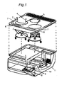
- Fig. 1 shows a configuration of a cooking device according to a first embodiment of the present invention.
- a top plate 2 made of crystallized ceramic, which is a top panel, is provided on the upper surface of a main body 1 serving as shell.
- a heating unit 3 for heating a cooking container 4, which is an object to be heated, placed on the top plate 2.
- three heating units 3 are arranged.
- Such heating units 3 are respectively configured by an induction heating coil for heating the cooking container 4 by induction heating, or a radiant heater for heating a pan that is not suited for induction heating.
- a heating display unit 5 for indicating a user a location to place the cooking container 4 is provided at a position facing the heating unit 3 on the surface of the top plate 2.
- a through-hole may be formed in the top plate 2 forming the upper surface of the device, and a gas burner may be provided at the portion of the through-hole as the heating unit.
- the object to be heated is placed on the gas burner that forms the upper surface of the main body.
- a top surface operation unit 6 including switches assigned with commands such as start and stop of heating of the heating unit 3 is arranged in a substantial same plane as the top plate 2.
- a top surface display unit 7 for displaying various states according to the operation of the top surface operation unit 6 is arranged on the top plate 2.
- the top surface display unit 7 is a notifying unit for notifying various states to the user by a liquid crystal, an LED, and the like. For example, when a switch that is set to be unusable is operated, the top surface display unit 7 notifies the user that the switch cannot be operated by flashing the LED, and the like.
- a front surface operation unit 8 of open/close storage type and a front surface display unit 9 for displaying various states according to the operation of the front surface operation unit 8 are provided on the front surface of the main body 1.
- the front surface display unit 9 is a notifying unit for notifying the user of various states by a liquid crystal, an LED, and the like.
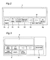
- Fig. 2 shows the top surface operation unit 6 and the top surface display unit 7 arranged on the top plate 2.
- the top surface operation unit 6 forms a touch switch of electrostatic capacity type for performing switch operation when the surface of the top plate 2 is touched in the case of arranging an electrode at the back surface of the top plate 2 and applying a high frequency voltage to the relevant electrode.
- the top surface operation unit 6 includes an unlock switch 6a assigned with a function of changing a control mode of the cooking device to a control mode in which the switch operations of the switches 6b to 6g of the top surface operation unit 6 can be performed; a timer switch 6b for transitioning to a timer mode as well as for setting a cooking time (set value) in a heating mode; an automatic switch 6c assigned with a function for selecting a control mode of automatically performing water boiling and rice cooking; a fried-food ON/OFF switch 6d used when selecting a fried-food cooking mode; a down switch 6e for lowering heating power and a temperature (set value); an up switch 6f for raising the heating power and the temperature (set value); and a heating ON/OFF switch 6g for changing from a stop mode to the heating mode and changing from the heating mode to the stop mode.
- an unlock switch 6a assigned with a function of changing a control mode of the cooking device to a control mode in which the switch operations of the switches 6b to 6g of the top surface operation unit
- the cooking device of the present embodiment has control modes including an unlock mode, the timer mode, an automatic cooking mode, a fried-food mode, and the heating mode, where the unlock switch 6a, the automatic switch 6c, the fried-food ON/OFF switch 6d, and the heating ON/OFF switch 6g correspond to the control mode switch for selecting the control mode.
- the timer switch 6b, the down switch 6e, and the up switch 6f are setting switches for selecting a set value in each control mode.
- the timer switch 6b is a setting switch, and at the same time, is used as a control mode switch for transitioning to the timer mode.
- the setting switch and the control mode switch may be made up of one switch.
- Fig. 3 shows the front surface operation unit 8 and the front surface display unit 9 arranged on the front surface of the main body 1.
- the front surface operation unit 8 includes a selection switch 8a for switching between a first operation mode (hereinafter also referred to as “full mode”) enabling all functions of the cooking device, and a second operation mode (hereinafter also referred to as “simple mode”) for limiting the enabled functions.
- full mode all control modes are set to be selectable, and all switches 6a to 6g of the top surface operation unit 6 are set to be enabled.
- the simple mode only the heating mode of the control modes is set to be selectable, and only the down switch 6e, the up switch 6f, and the heating ON/OFF switch 6g used in the heating mode are set to be enabled.
- Fig. 4 is a block diagram showing a configuration of the cooking device of the present embodiment.
- the cooking device of the present embodiment includes a heating control unit 10 for controlling the heating unit 3 and switching the number of enabled control modes based on the operation of the selection switch 8a.
- the heating control unit 10 controls the heating unit 3 based on the switch operations of the top surface operation unit 6 and the front surface operation unit 8.
- the heating control unit 10 sets the control mode selectable by the top surface operation unit 6 according to the operation mode selected by the selection switch 8a. Further, the heating control unit 10 switches so that only the setting switch necessary for the execution of the relevant control mode can be operated, and displays the control mode switch and the setting switch usable at the top surface display unit 7 and switches to perform a display showing the operation mode currently selected at the front surface display unit 9.
- the heating control unit 10 accepts the operation of the selection switch 8a, and switches from the full mode to the simple mode or from the simple mode to the full mode.
- the heating control unit 10 accepts the operation of such a switch.
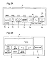
- Fig. 5A shows a state of the top surface operation unit 6 and the top surface display unit 7 when the power switch 15 is turned on
- Fig. 5B shows a state of the front surface operation unit 8 and the front surface display unit 9 when the power switch 15 is turned on.
- the unlock mode, the timer mode, the automatic cooking mode, the fried-food mode, and the heating mode are all set to be selectable, and all switches 6a to 6g of the top surface display unit 7 are set to be enabled, an indication 50 by the light-emitting element is displayed at the upper part of all switches of the top surface display unit 7 to show that all switches 6a to 6g are usable, as shown in Fig. 5A .
- characters "F mode" indicating the full mode are displayed on the front surface display unit 9.
- the operation of starting the heating of the cooking container 4 (operation of starting the heating mode) when the full mode is selected is carried out through a procedure of operating the unlock switch 6a (first procedure), and operating the heating ON/OFF switch 6g (second procedure).
- the unlock switch 6a is in a enabled state when the selection switch 8a of the front surface operation unit 8 is operated and the simple mode is not selected, and thus the heating control unit 10 controls the heating unit 3 to start heating when accepting the operation of the unlock switch 6a and then accepting the operation of the heating ON/OFF switch 6g.
- Fig. 6A shows a state of the top surface operation unit 6 and the top surface display unit 7 when the heating mode is selected and heating is being carried out in the full mode
- Fig. 6B shows a state of the front surface operation unit 8 and the front surface display unit 9 when the heating mode is selected and heating is being carried out in the full mode.
- a heating power set value 7b and a timer set time 7a are displayed in the top surface display unit 7.
- a selecting function of the heating power set value by the operation of the down switch 6e (setting switch) and the up switch 6f (setting switch), a selecting function of the time set value of the cooking timer by the timer switch 6b (setting switch), and a stop function of heating by the heating ON/OFF switch 6g (control mode switch) are usable.
- the indication 50 by the light-emitting element is displayed in the top surface display unit 7 at the upper part of the usable switches 6a, 6b, 6e, 6f, and 6g. Even if the switches 6c and 6d without the indication 50 are operated, the control unit 10 does not accept the operation thereof. Therefore, in the full mode, the enabled control mode switch and the enabled setting switch, and the disabled control mode switch and the disabled setting switch are notified in a distinguished manner according to the selected control mode (heating mode in the case of Fig. 6 ).
- the user When a switch without the indication 50 is operated for one or more seconds, the user is notified that the switch operated by the top surface display unit 7 is unusable. For example, when the disabled switch is operated, the top surface display unit 7 blinks the indication 50 corresponding to the operated switch for a predetermined period of time.
- Fig. 7A shows a state of the top surface operation unit 6 and the top surface display unit 7 when switched to the simple mode after the power is turned on
- Fig. 7B shows a state of the front surface operation unit 8 and the front surface display unit 9 when switched to the simple mode after the power is turned on.
- the down switch 6e, the up switch 6f, and the heating ON/OFF switch 6g which operation is valid in the simple mode, are arranged adjacent to at least one switch, which operation is valid. The user can thus easily distinguish the usable control mode switch and the usable setting switch from the unusable control mode switch and the unusable setting switch.
- the operation of starting heating of the cooking container 4 is carried out only by operating the heating ON/OFF switch 6g (first procedure).
- the heating control unit 15 sets the unlock switch 6a to be disabled, and thus the heating control unit 10 controls the heating unit 3 and starts heating immediately after accepting the operation of the heating ON/OFF switch 6g.
- the unlock switch 6a is set to be disabled, and thus the heating control unit 10 does not accept the operation of the unlock switch 6a and the top surface display unit 7 does not change even if the operation of the unlock switch 6a is performed before the operation of the heating ON/OFF switch 6g.
- Fig. 8A shows a state of the top surface operation unit 6 and the top surface display unit 7 when the heating mode is selected and heating is being carried out in the simple mode
- Fig. 8B shows a state of the front surface operation unit 8 and the front surface display unit 9 when the heating mode is selected and heating is being carried out in the simple mode
- the heating power set value 7b is displayed in the top surface display unit 7 during heating.
- the timer set time 7a shown in Fig. 6A is not displayed since the timer function cannot be used.
- the adjustment function of the heating power by the operation of the down switch 6e and the up switch 6f, and the stop function of heating by the heating ON/OFF switch 6g are usable.
- the indication 50 by the light-emitting element is displayed in the top surface display unit 7 over the usable switch. Even if the switch without the indication 50 is operated, the heating control unit 10 does not accept the operation thereof.
- the number of selectable control modes is changed and only the switches necessary for the selectable control mode are made enabled, by the operation of the selection switch 8a. Therefore, the operation procedure for starting heating also changes according to the selected operation mode.
- a user who desires to use all the functions does not operate the selection switch 8a after turning on the power and performs the operation with the "F mode" displayed on the front surface display unit 9, so that heating can be performed in a state where a great number of functions can be used with a great number of switches that can be used.
- a user who does not need to use all the functions and desires to perform heating with a simple operation operates the selection switch 8a and performs the operation with the "S mode" displayed on the front surface display unit 7, so that the number of switches that can be used is reduced, and heating and adjustment of the heating power can be carried out with a simpler operation.
- the correct operation can be induced by notifying the user with the top surface display unit 7 when the switch set to be disabled is operated.
- the usable switch is arranged to be adjacent to at least another usable switch in the simple mode, a plurality of enabled switches can be grouped, and the user can more easily distinguish the usable switch from the unusable switch. The operation is thus easier to perform.
- the time (three seconds) required to accept the operation of the selection switch 8a is set longer than the time (one second) required to accept the operations of the switches 6a to 6g of the top surface operation unit 6, the operation of the selection switch 8a is hard to accept in comparison with the operations of the control mode switches 6a, 6c, 6d, 6g and the setting switches 6b, 6e, 6f. Therefore, the selection switch 8a is prevented from being carelessly operated. The selection switch 8a is thus prevented from being unconsciously operated by the user.
- the time required for accepting the switch is set to one second and three seconds for the switches 6a to 6g of the top surface operation unit 6 and the selection switch 8a, respectively, but such time is not limited to the present embodiment.
- the number of operations required for accepting the switch may be arbitrarily set.
- the function assigned to the switch may be executed when the switch is operated a plurality of times within a certain period of time.
- the number of operations (e.g., two times) required for accepting the selection switch 8a within the certain period of time is set greater than the number of operations (e.g., once) required for accepting the switches 6a to 6g of the top surface operation unit 6, so that the operation of the selection switch 8a is harder to accept than the operation of the control mode switches 6a, 6c, 6d, 6g and the setting switches 6b, 6e, 6f.
- the selection switch 8a and the other switch are simultaneously operated, the other switch is accepted and the selection switch 8a is not accepted, so that the selection switch 8a is harder to accept than the other switch.
- the top surface display unit 7 when the switch set to be disabled is operated, the top surface display unit 7 notifies the user that such switch cannot be operated, but the front surface display unit 9 may notify the user that the switch cannot be operated, instead of the top surface display unit 7.
- the operation of the selection switch 8a may be performed at any time, or the operable timing thereof can be limited. For example, operation may be possible only within a predetermined time after the power is turned on.
- the switching from the full mode to the simple mode and the switching from the simple mode to the full mode are enabled by the selection switch 8a, but only the switching from the full mode to the simple mode may be enabled by the operation of the selection switch 8a, and the mode may be returned to the full mode every time the power of the cooking device is turned on.
- the cooking device has two operations modes, the full mode and the simple mode, but three or more operation modes may be provided.
- the enabled function may be set according to the respective operation modes.
- Fig. 9 shows a configuration of a cooking device of a second embodiment.
- the cooking device of the first embodiment is started up in the full mode when the power is turned on, but the cooking device of the second embodiment is started up in the stored operation mode (i.e., previously set operation mode).
- the cooking device of the present embodiment further includes a non-volatile memory 11, which communicates with the heating control unit 10, in addition to the configuration of the first embodiment.
- the non-volatile memory 11 stores whether the cooking device is operating in the simple mode or is operating in the full mode.
- the heating control unit 10 records, on the non-volatile memory 11, the operation state of the device (operation state indicating full mode or simple mode) when the main power of the cooking device is turned off by the user.
- the heating control unit 10 reads the state of the device before the power switch 15 is turned off from the non-volatile memory 11.
- the indication 50 by the light-emitting element is displayed on the top surface display unit 7 over the down switch 6e, the up switch 6f, and the heating ON/OFF switch 6g to indicate that only the down switch 6e, the up switch 6f, and the heating ON/OFF switch 6g are usable, and to indicate that other switches cannot be operated, as shown in Fig. 7A .
- the "S mode" is displayed in the front surface display unit 9.
- the trouble of operating the selection switch 8a every time after the power is turned on can be saved since the operation mode before turning off the power is stored even if the power switch 15 of the cooking device is turned off.
- the enabled switches are indicated with the indication 50 in the first embodiment and the second embodiment, but the top surface operation unit 6 may have backlights corresponding to all of the plurality of switches 6a to 6g below each switch to notify only the enabled switches.
- a display example of the simple mode after the power is turned on in such a case is shown in Figs. 10A and 10B . Only the switches 6e, 6f, 6g may be displayed by turning on the backlights arranged below the enabled switches 6e, 6f, 6g, and the switches 6a, 6b, 6c, 6d may not be displayed by turning off the backlights arranged below the disabled switches 6a, 6b, 6c, 6d. According to such a configuration, the user does not mistakenly operate the disabled switches.
- the automatic switch 6c, the fried-food ON/OFF switch 6d, and the heating ON/OFF switch 6g are individually arranged as control mode switches, but the configuration is not limited thereto.
- a "menu switch" (not shown) may be arranged as the control mode switch, where the control mode to be selected may be changed in rotation every time the relevant switch is operated, and the heating ON/OFF switch may be operated after selecting the control mode to start heating. Therefore, two or more control mode switches may be operated to transit the control mode.
- the induction cooking device having the heating coil as the heating unit 3 has been described, but the present invention is not limited to this type of cooking device.
- a cooking device in which the heating unit is a radiant type, a halogen lamp type, or a gas type may also be adopted.
- the cooking device of the present invention has an effect in that a user who only uses basic functions can easily use the device having a great number of functions and a great number of switches, and is useful for a device having a great number of functions and a great number of switches, and the like.
Landscapes
- Engineering & Computer Science (AREA)
- Physics & Mathematics (AREA)
- Electromagnetism (AREA)
- Chemical & Material Sciences (AREA)
- Combustion & Propulsion (AREA)
- Mechanical Engineering (AREA)
- General Engineering & Computer Science (AREA)
- Electric Stoves And Ranges (AREA)
- Cookers (AREA)
- Induction Heating Cooking Devices (AREA)
- Electric Ovens (AREA)
Claims (7)
- Appareil de cuisson comprenant:un corps de base (1) servant de boîtier;une plaque supérieure (2) prévue sur une surface supérieure dudit corps de base (1);une unité de chauffage (3) adaptée pour chauffer un objet à chauffer placé sur la surface supérieure du corps de base (1);une pluralité d'interrupteurs de mode de commande (6a, 6b, 6c, 6d, 6g) dont chacun est adapté pour choisir un dans une pluralité de modes de commande afin de commander un processus de chauffage de ladite unité de chauffage (3);au moins un interrupteur de réglage (6b, 6e, 6f) adapté pour choisir une valeur de réglage dans chaque mode de commande;une unité de commande de chauffage (10) adaptée pour commander ladite unité de chauffage (3) sur la base du mode de commande et de la valeur de réglage entrés par les interrupteurs de mode de commande (6a, 6b, 6c, 6d, 6g) et l'interrupteur de réglage (6b, 6e, 6f); etun sélecteur (8a) adapté pour choisir un mode de fonctionnement dans une pluralité de modes de fonctionnement;caractérisé par le fait queles modes de fonctionnement comprennent un premier mode de fonctionnement dans lequel tous de ladite pluralité de modes de commande sont réglés afin d'être choisissables, ainsi qu'un deuxième mode de fonctionnement dans lequel seulement une partie de ladite pluralité de modes de commande est réglée afin d'être choisissable;que, lorsque le premier mode de fonctionnement est choisi par le sélecteur (8a), ladite unité de commande de chauffage (10) active l'ensemble des interrupteurs de mode de commande (6a, 6b, 6c, 6d, 6g) de sorte que tous de ladite pluralité de modes de commande sont réglés afin d'être choisissables;que, lorsque le deuxième mode de fonctionnement est choisi par le sélecteur (8a), ladite unité de commande de chauffage (10) désactive au moins un parmi les interrupteurs de mode de commande (6a, 6b, 6c, 6d, 6g) de sorte que seulement une partie de ladite pluralité de modes de commande est réglée afin d'être choisissable; etque ladite unité de commande de chauffage (10) règle uniquement l'interrupteur de réglage qui est nécessaire aux modes de commande qui sont réglés afin d'être choisissables dans le mode de fonctionnement choisi par le sélecteur afin d'être activé.
- Appareil de cuisson selon la revendication 1, comprenant en outre une première unité d'affichage (7) adaptée pour indiquer de toute évidence l'interrupteur de mode de commande (6g) activé et l'interrupteur de réglage (6e, 6f) activé par rapport à l'interrupteur de mode de commande (6a, 6b, 6c, 6d, 6e) désactivé et l'interrupteur de réglage désactivé dans le deuxième mode de fonctionnement.
- Appareil de cuisson selon la revendication 1, dans lequel l'interrupteur de mode de commande (6g) activé et l'interrupteur de réglage (6e, 6f) activé sont disposés de manière adjacente à au moins un autre interrupteur de mode de commande activé ou interrupteur de réglage activé dans le deuxième mode de fonctionnement.
- Appareil de cuisson selon la revendication 2, comprenant en outre une deuxième unité d'affichage (9) adaptée pour indiquer si ledit appareil de cuisson fonctionne dans le premier mode de fonctionnerrient ou dans le deuxième mode de fonctionnement;
dans lequel, lorsque ledit interrupteur de mode de commande ou interrupteur de réglage désactivé est actionné, au moins l'une parmi ladite première unité d'affichage (7) ou ladite deuxième unité d'affichage (9) indique que l'interrupteur de mode de commande actionné ou l'interrupteur de réglage actionné est désactivé. - Appareil de cuisson selon la revendication 1, configuré pour que le sélecteur (8a) ne soit pas accepté lorsque le sélecteur (8a) et l'un parmi les interrupteurs de mode de commande (6a, 6b, 6c, 6d, 6g) et l'interrupteur de réglage (6b, 6e, 6f) sont actionnés simultanément.
- Appareil de cuisson selon la revendication 1, dans lequel ledit sélecteur (8a) est un interrupteur qui présente un contact électrique et est adapté pour ouvrir et fermer; et dans lequel les interrupteurs de mode de commande (6a, 6b, 6c, 6d, 6g) et l'interrupteur de réglage (6b, 6e, 6f) sont des interrupteurs tactiles de type électrostatique capacitif.
- Appareil de cuisson selon la revendication 1, comprenant en outre:un interrupteur de marche-arrêt (15) adapté pour désactiver toutes les opérations dans un état arrêt de l'interrupteur de marche-arrêt (15) et pour activer au moins un interrupteur à actionner dans un état marche de l'interrupteur de marche-arrêt; etune mémoire non volatile (11) adaptée pour mémoriser le mode de fonctionnement choisi par le sélecteur (8a) lorsque l'interrupteur de marche-arrêt (15) est en état marche;dans lequel l'appareil de cuisson fonctionne dans le mode de fonctionnement mémorisé lorsque l'interrupteur de marche-arrêt (15) est allumé.
Applications Claiming Priority (2)
| Application Number | Priority Date | Filing Date | Title |
|---|---|---|---|
| JP2007187914 | 2007-07-19 | ||
| PCT/JP2008/001926 WO2009011130A1 (fr) | 2007-07-19 | 2008-07-18 | Dispositif de cuisson |
Publications (3)
| Publication Number | Publication Date |
|---|---|
| EP2180258A1 EP2180258A1 (fr) | 2010-04-28 |
| EP2180258A4 EP2180258A4 (fr) | 2012-07-25 |
| EP2180258B1 true EP2180258B1 (fr) | 2015-05-20 |
Family
ID=40259476
Family Applications (1)
| Application Number | Title | Priority Date | Filing Date |
|---|---|---|---|
| EP20080790228 Active EP2180258B1 (fr) | 2007-07-19 | 2008-07-18 | Dispositif de cuisson |
Country Status (7)
| Country | Link |
|---|---|
| US (1) | US8338757B2 (fr) |
| EP (1) | EP2180258B1 (fr) |
| JP (1) | JP5368986B2 (fr) |
| CN (1) | CN101755170B (fr) |
| ES (1) | ES2543379T3 (fr) |
| HK (1) | HK1143855A1 (fr) |
| WO (1) | WO2009011130A1 (fr) |
Families Citing this family (27)
| Publication number | Priority date | Publication date | Assignee | Title |
|---|---|---|---|---|
| CN102047755B (zh) | 2009-02-06 | 2013-10-02 | 松下电器产业株式会社 | 电磁烹调器 |
| JP5223782B2 (ja) * | 2009-06-02 | 2013-06-26 | パナソニック株式会社 | 誘導加熱装置 |
| EP2392859B1 (fr) * | 2010-05-05 | 2017-03-29 | Electrolux Home Products Corporation N.V. | Interface de table de cuisson, panneau de table de cuisson, dispositif de cuisson et procédé de fonctionnement d'une interface de table de cuisson |
| JP5601901B2 (ja) * | 2010-06-28 | 2014-10-08 | 三菱電機株式会社 | 加熱調理器 |
| JP2012038458A (ja) * | 2010-08-04 | 2012-02-23 | Mitsubishi Electric Corp | 加熱調理器 |
| DE112011102785T5 (de) * | 2010-08-23 | 2013-05-29 | Mitsubishi Electric Corporation | Kochheizvorrichtung |
| DE102011053990A1 (de) * | 2011-09-27 | 2013-03-28 | Vorwerk & Co. Interholding Gmbh | Verfahren zur benutzerdefinierten Freischaltung einer elektrischen Küchenmaschine sowie elektrisch betriebene Küchenmaschine |
| JP6053562B2 (ja) * | 2013-02-21 | 2016-12-27 | 大阪瓦斯株式会社 | 加熱調理システム及び加熱調理システム用アプリケーションプログラム |
| JP5657066B1 (ja) * | 2013-07-08 | 2015-01-21 | シャープ株式会社 | 加熱調理器 |
| JP6417087B2 (ja) * | 2013-09-11 | 2018-10-31 | 株式会社パロマ | 加熱調理器 |
| JP6375513B2 (ja) * | 2014-05-29 | 2018-08-22 | パナソニックIpマネジメント株式会社 | 加熱調理器 |
| KR101626490B1 (ko) * | 2014-12-17 | 2016-06-01 | 엘지전자 주식회사 | 조리기기 및 그 제어방법 |
| KR101713436B1 (ko) | 2015-09-03 | 2017-03-07 | 엘지전자 주식회사 | 가스 조리기기 |
| JP6637770B2 (ja) * | 2016-01-19 | 2020-01-29 | リンナイ株式会社 | 加熱調理器 |
| CN106571802B (zh) * | 2016-10-26 | 2020-01-14 | 宁波方太厨具有限公司 | 一种具有非接触感应旋钮开关的设备的工作状态控制方法 |
| EP3865028A1 (fr) | 2017-08-09 | 2021-08-18 | SharkNinja Operating LLC | Dispositif de cuisson et ses composants |
| JP6480547B2 (ja) * | 2017-11-30 | 2019-03-13 | 株式会社パロマ | 加熱調理器 |
| USD914436S1 (en) | 2018-06-19 | 2021-03-30 | Sharkninja Operating Llc | Air diffuser with food preparation pot |
| USD883015S1 (en) | 2018-08-09 | 2020-05-05 | Sharkninja Operating Llc | Food preparation device and parts thereof |
| USD934027S1 (en) | 2018-08-09 | 2021-10-26 | Sharkninja Operating Llc | Reversible cooking rack |
| USD883014S1 (en) | 2018-08-09 | 2020-05-05 | Sharkninja Operating Llc | Food preparation device |
| USD903413S1 (en) | 2018-08-09 | 2020-12-01 | Sharkninja Operating Llc | Cooking basket |
| US11051654B2 (en) | 2019-02-25 | 2021-07-06 | Sharkninja Operating Llc | Cooking device and components thereof |
| WO2020176477A1 (fr) | 2019-02-25 | 2020-09-03 | Sharkninja Operating Llc | Système de cuisson avec protection |
| USD982375S1 (en) | 2019-06-06 | 2023-04-04 | Sharkninja Operating Llc | Food preparation device |
| USD918654S1 (en) | 2019-06-06 | 2021-05-11 | Sharkninja Operating Llc | Grill plate |
| US11678765B2 (en) | 2020-03-30 | 2023-06-20 | Sharkninja Operating Llc | Cooking device and components thereof |
Family Cites Families (21)
| Publication number | Priority date | Publication date | Assignee | Title |
|---|---|---|---|---|
| US4345145A (en) * | 1980-05-19 | 1982-08-17 | General Electric Company | User programmable control system for toaster oven appliance |
| US4695711A (en) * | 1984-12-24 | 1987-09-22 | Robershaw Controls Company | Electrically operated appliance controls and methods of making the same |
| US4968515A (en) * | 1988-09-01 | 1990-11-06 | Henny Penny Corporation | Rotisserie control device |
| CN1043012A (zh) * | 1988-11-29 | 1990-06-13 | 食品自动化服务技术公司 | 用于烹调装置的温度控制系统 |
| JP3438292B2 (ja) | 1994-02-04 | 2003-08-18 | 株式会社ニコン | 情報の選択的入力が可能なカメラ |
| US5594524A (en) * | 1994-02-04 | 1997-01-14 | Nikon Corporation | Camera for selectively inputting operating parameters and method |
| DE19606115A1 (de) * | 1995-02-20 | 1996-08-22 | Miele & Cie | Bedienblende eines Haushaltgerätes und Verfahren zur Steuerung eines Programmes |
| US5847365A (en) * | 1996-06-06 | 1998-12-08 | Garland Commercial Industries, Inc. | Instant-on cooking device controller |
| US6066837A (en) * | 1999-04-16 | 2000-05-23 | Thermador Corporation | Method and apparatus for sabbath compliance cooking process |
| US6198080B1 (en) * | 1999-08-05 | 2001-03-06 | General Electric Company | Glass touch cooktop dual element and bridge burner control |
| DE20002948U1 (de) | 2000-02-21 | 2001-06-28 | Diehl Controls Nuernberg Gmbh | Bedienblende für einen Elektrobackofen |
| US6987250B2 (en) * | 2000-04-28 | 2006-01-17 | The Holmes Group, Inc. | Control circuit for kitchen appliances |
| US6781097B2 (en) * | 2001-12-21 | 2004-08-24 | Emerson Electric Co. | System and method for proportional control of oven heating elements |
| JP3620502B2 (ja) | 2002-01-16 | 2005-02-16 | 松下電器産業株式会社 | 加熱調理器 |
| JP2004363005A (ja) * | 2003-06-06 | 2004-12-24 | Mitsubishi Electric Corp | 加熱調理器 |
| JP2005009831A (ja) | 2003-06-20 | 2005-01-13 | Rinnai Corp | 操作パネル |
| JP2005308266A (ja) * | 2004-04-20 | 2005-11-04 | Tokyo Gas Co Ltd | 調理機器及びそれを用いた調理方法 |
| JP2006171107A (ja) | 2004-12-13 | 2006-06-29 | Nikon Corp | カメラ |
| JP2007173065A (ja) | 2005-12-22 | 2007-07-05 | Matsushita Electric Ind Co Ltd | 加熱調理器 |
| EP2247158B1 (fr) * | 2008-02-19 | 2017-03-29 | Panasonic Corporation | Dispositif de cuisson à induction |
| JP5280192B2 (ja) * | 2008-12-26 | 2013-09-04 | 株式会社パロマ | 加熱調理器 |
-
2008
- 2008-07-18 JP JP2009523544A patent/JP5368986B2/ja active Active
- 2008-07-18 EP EP20080790228 patent/EP2180258B1/fr active Active
- 2008-07-18 US US12/669,614 patent/US8338757B2/en active Active
- 2008-07-18 ES ES08790228.4T patent/ES2543379T3/es active Active
- 2008-07-18 CN CN2008800253421A patent/CN101755170B/zh active Active
- 2008-07-18 WO PCT/JP2008/001926 patent/WO2009011130A1/fr active Application Filing
-
2010
- 2010-11-05 HK HK10110387.8A patent/HK1143855A1/xx not_active IP Right Cessation
Also Published As
| Publication number | Publication date |
|---|---|
| ES2543379T3 (es) | 2015-08-18 |
| US20100187217A1 (en) | 2010-07-29 |
| JP5368986B2 (ja) | 2013-12-18 |
| JPWO2009011130A1 (ja) | 2010-09-16 |
| CN101755170A (zh) | 2010-06-23 |
| CN101755170B (zh) | 2012-06-06 |
| EP2180258A1 (fr) | 2010-04-28 |
| EP2180258A4 (fr) | 2012-07-25 |
| US8338757B2 (en) | 2012-12-25 |
| HK1143855A1 (en) | 2011-01-14 |
| WO2009011130A1 (fr) | 2009-01-22 |
Similar Documents
| Publication | Publication Date | Title |
|---|---|---|
| EP2180258B1 (fr) | Dispositif de cuisson | |
| EP2202462B1 (fr) | Dispositif de cuisson | |
| CN103493587B (zh) | 带有锅检测装置的电磁炉铁架以及用于操作电磁炉铁架的方法 | |
| AU2013354402B2 (en) | A cooking hob including a user interface | |
| US20110114620A1 (en) | Cooking appliance | |
| EP2506674B1 (fr) | Plaque de cuisson à induction avec un dispositif de détection de pot | |
| CN103901910A (zh) | 加热装置及其控制方法 | |
| JP4879564B2 (ja) | 加熱調理器 | |
| JP2009231175A (ja) | 誘導加熱調理器とそのプログラム | |
| JP6375513B2 (ja) | 加熱調理器 | |
| JP5270848B2 (ja) | 誘導加熱調理器 | |
| JP2010282739A (ja) | 誘導加熱装置 | |
| JP3551859B2 (ja) | 炊飯器 | |
| JP4906575B2 (ja) | 炊飯器 | |
| JP2007280700A (ja) | 加熱調理器 | |
| JP6110733B2 (ja) | 加熱調理装置 | |
| JP6804394B2 (ja) | 調理器の表示装置 | |
| JP2009081007A (ja) | 誘導加熱調理器 | |
| JP3349690B2 (ja) | 炊飯器 | |
| JP4998420B2 (ja) | 誘導加熱調理器 | |
| ES2936617T3 (es) | Aparato doméstico y procedimiento de control de un aparato doméstico | |
| JP3892975B2 (ja) | 炊飯器の操作装置 | |
| EP3001108B1 (fr) | Appareil ménager électronique | |
| CN114585125A (zh) | 感应加热烹调器以及计算机程序的存储介质 | |
| JP2004222936A (ja) | 調理器の液晶表示装置 |
Legal Events
| Date | Code | Title | Description |
|---|---|---|---|
| PUAI | Public reference made under article 153(3) epc to a published international application that has entered the european phase |
Free format text: ORIGINAL CODE: 0009012 |
|
| 17P | Request for examination filed |
Effective date: 20100219 |
|
| AK | Designated contracting states |
Kind code of ref document: A1 Designated state(s): AT BE BG CH CY CZ DE DK EE ES FI FR GB GR HR HU IE IS IT LI LT LU LV MC MT NL NO PL PT RO SE SI SK TR |
|
| AX | Request for extension of the european patent |
Extension state: AL BA MK RS |
|
| DAX | Request for extension of the european patent (deleted) | ||
| A4 | Supplementary search report drawn up and despatched |
Effective date: 20120626 |
|
| RIC1 | Information provided on ipc code assigned before grant |
Ipc: F24C 7/04 20060101AFI20120620BHEP Ipc: H05B 6/06 20060101ALN20120620BHEP Ipc: F24C 15/00 20060101ALI20120620BHEP Ipc: H05B 6/12 20060101ALI20120620BHEP Ipc: F24C 7/08 20060101ALN20120620BHEP |
|
| 17Q | First examination report despatched |
Effective date: 20140415 |
|
| GRAP | Despatch of communication of intention to grant a patent |
Free format text: ORIGINAL CODE: EPIDOSNIGR1 |
|
| RIC1 | Information provided on ipc code assigned before grant |
Ipc: H05B 6/12 20060101ALI20141119BHEP Ipc: F24C 15/00 20060101ALI20141119BHEP Ipc: F24C 7/04 20060101AFI20141119BHEP Ipc: F24C 7/08 20060101ALN20141119BHEP Ipc: H05B 6/06 20060101ALN20141119BHEP |
|
| INTG | Intention to grant announced |
Effective date: 20141210 |
|
| GRAS | Grant fee paid |
Free format text: ORIGINAL CODE: EPIDOSNIGR3 |
|
| GRAA | (expected) grant |
Free format text: ORIGINAL CODE: 0009210 |
|
| AK | Designated contracting states |
Kind code of ref document: B1 Designated state(s): AT BE BG CH CY CZ DE DK EE ES FI FR GB GR HR HU IE IS IT LI LT LU LV MC MT NL NO PL PT RO SE SI SK TR |
|
| REG | Reference to a national code |
Ref country code: GB Ref legal event code: FG4D |
|
| REG | Reference to a national code |
Ref country code: CH Ref legal event code: EP |
|
| REG | Reference to a national code |
Ref country code: AT Ref legal event code: REF Ref document number: 727928 Country of ref document: AT Kind code of ref document: T Effective date: 20150615 |
|
| REG | Reference to a national code |
Ref country code: IE Ref legal event code: FG4D |
|
| REG | Reference to a national code |
Ref country code: FR Ref legal event code: PLFP Year of fee payment: 8 |
|
| REG | Reference to a national code |
Ref country code: DE Ref legal event code: R096 Ref document number: 602008038248 Country of ref document: DE |
|
| REG | Reference to a national code |
Ref country code: ES Ref legal event code: FG2A Ref document number: 2543379 Country of ref document: ES Kind code of ref document: T3 Effective date: 20150818 |
|
| PGFP | Annual fee paid to national office [announced via postgrant information from national office to epo] |
Ref country code: FR Payment date: 20150626 Year of fee payment: 8 |
|
| REG | Reference to a national code |
Ref country code: AT Ref legal event code: MK05 Ref document number: 727928 Country of ref document: AT Kind code of ref document: T Effective date: 20150520 |
|
| REG | Reference to a national code |
Ref country code: LT Ref legal event code: MG4D |
|
| REG | Reference to a national code |
Ref country code: NL Ref legal event code: MP Effective date: 20150520 |
|
| PG25 | Lapsed in a contracting state [announced via postgrant information from national office to epo] |
Ref country code: LT Free format text: LAPSE BECAUSE OF FAILURE TO SUBMIT A TRANSLATION OF THE DESCRIPTION OR TO PAY THE FEE WITHIN THE PRESCRIBED TIME-LIMIT Effective date: 20150520 Ref country code: NO Free format text: LAPSE BECAUSE OF FAILURE TO SUBMIT A TRANSLATION OF THE DESCRIPTION OR TO PAY THE FEE WITHIN THE PRESCRIBED TIME-LIMIT Effective date: 20150820 Ref country code: PT Free format text: LAPSE BECAUSE OF FAILURE TO SUBMIT A TRANSLATION OF THE DESCRIPTION OR TO PAY THE FEE WITHIN THE PRESCRIBED TIME-LIMIT Effective date: 20150921 Ref country code: FI Free format text: LAPSE BECAUSE OF FAILURE TO SUBMIT A TRANSLATION OF THE DESCRIPTION OR TO PAY THE FEE WITHIN THE PRESCRIBED TIME-LIMIT Effective date: 20150520 Ref country code: HR Free format text: LAPSE BECAUSE OF FAILURE TO SUBMIT A TRANSLATION OF THE DESCRIPTION OR TO PAY THE FEE WITHIN THE PRESCRIBED TIME-LIMIT Effective date: 20150520 |
|
| PGFP | Annual fee paid to national office [announced via postgrant information from national office to epo] |
Ref country code: ES Payment date: 20150728 Year of fee payment: 8 |
|
| PG25 | Lapsed in a contracting state [announced via postgrant information from national office to epo] |
Ref country code: GR Free format text: LAPSE BECAUSE OF FAILURE TO SUBMIT A TRANSLATION OF THE DESCRIPTION OR TO PAY THE FEE WITHIN THE PRESCRIBED TIME-LIMIT Effective date: 20150821 Ref country code: IS Free format text: LAPSE BECAUSE OF FAILURE TO SUBMIT A TRANSLATION OF THE DESCRIPTION OR TO PAY THE FEE WITHIN THE PRESCRIBED TIME-LIMIT Effective date: 20150920 Ref country code: BG Free format text: LAPSE BECAUSE OF FAILURE TO SUBMIT A TRANSLATION OF THE DESCRIPTION OR TO PAY THE FEE WITHIN THE PRESCRIBED TIME-LIMIT Effective date: 20150820 Ref country code: AT Free format text: LAPSE BECAUSE OF FAILURE TO SUBMIT A TRANSLATION OF THE DESCRIPTION OR TO PAY THE FEE WITHIN THE PRESCRIBED TIME-LIMIT Effective date: 20150520 Ref country code: LV Free format text: LAPSE BECAUSE OF FAILURE TO SUBMIT A TRANSLATION OF THE DESCRIPTION OR TO PAY THE FEE WITHIN THE PRESCRIBED TIME-LIMIT Effective date: 20150520 |
|
| PG25 | Lapsed in a contracting state [announced via postgrant information from national office to epo] |
Ref country code: EE Free format text: LAPSE BECAUSE OF FAILURE TO SUBMIT A TRANSLATION OF THE DESCRIPTION OR TO PAY THE FEE WITHIN THE PRESCRIBED TIME-LIMIT Effective date: 20150520 Ref country code: DK Free format text: LAPSE BECAUSE OF FAILURE TO SUBMIT A TRANSLATION OF THE DESCRIPTION OR TO PAY THE FEE WITHIN THE PRESCRIBED TIME-LIMIT Effective date: 20150520 |
|
| REG | Reference to a national code |
Ref country code: DE Ref legal event code: R097 Ref document number: 602008038248 Country of ref document: DE |
|
| PG25 | Lapsed in a contracting state [announced via postgrant information from national office to epo] |
Ref country code: MC Free format text: LAPSE BECAUSE OF FAILURE TO SUBMIT A TRANSLATION OF THE DESCRIPTION OR TO PAY THE FEE WITHIN THE PRESCRIBED TIME-LIMIT Effective date: 20150520 Ref country code: CZ Free format text: LAPSE BECAUSE OF FAILURE TO SUBMIT A TRANSLATION OF THE DESCRIPTION OR TO PAY THE FEE WITHIN THE PRESCRIBED TIME-LIMIT Effective date: 20150520 Ref country code: SK Free format text: LAPSE BECAUSE OF FAILURE TO SUBMIT A TRANSLATION OF THE DESCRIPTION OR TO PAY THE FEE WITHIN THE PRESCRIBED TIME-LIMIT Effective date: 20150520 Ref country code: PL Free format text: LAPSE BECAUSE OF FAILURE TO SUBMIT A TRANSLATION OF THE DESCRIPTION OR TO PAY THE FEE WITHIN THE PRESCRIBED TIME-LIMIT Effective date: 20150520 Ref country code: RO Free format text: LAPSE BECAUSE OF NON-PAYMENT OF DUE FEES Effective date: 20150520 |
|
| REG | Reference to a national code |
Ref country code: CH Ref legal event code: PL |
|
| PLBE | No opposition filed within time limit |
Free format text: ORIGINAL CODE: 0009261 |
|
| STAA | Information on the status of an ep patent application or granted ep patent |
Free format text: STATUS: NO OPPOSITION FILED WITHIN TIME LIMIT |
|
| PG25 | Lapsed in a contracting state [announced via postgrant information from national office to epo] |
Ref country code: LU Free format text: LAPSE BECAUSE OF FAILURE TO SUBMIT A TRANSLATION OF THE DESCRIPTION OR TO PAY THE FEE WITHIN THE PRESCRIBED TIME-LIMIT Effective date: 20150718 |
|
| REG | Reference to a national code |
Ref country code: IE Ref legal event code: MM4A |
|
| 26N | No opposition filed |
Effective date: 20160223 |
|
| PG25 | Lapsed in a contracting state [announced via postgrant information from national office to epo] |
Ref country code: LI Free format text: LAPSE BECAUSE OF NON-PAYMENT OF DUE FEES Effective date: 20150731 Ref country code: CH Free format text: LAPSE BECAUSE OF NON-PAYMENT OF DUE FEES Effective date: 20150731 Ref country code: IT Free format text: LAPSE BECAUSE OF FAILURE TO SUBMIT A TRANSLATION OF THE DESCRIPTION OR TO PAY THE FEE WITHIN THE PRESCRIBED TIME-LIMIT Effective date: 20150520 |
|
| PG25 | Lapsed in a contracting state [announced via postgrant information from national office to epo] |
Ref country code: SI Free format text: LAPSE BECAUSE OF FAILURE TO SUBMIT A TRANSLATION OF THE DESCRIPTION OR TO PAY THE FEE WITHIN THE PRESCRIBED TIME-LIMIT Effective date: 20150520 |
|
| PG25 | Lapsed in a contracting state [announced via postgrant information from national office to epo] |
Ref country code: IE Free format text: LAPSE BECAUSE OF NON-PAYMENT OF DUE FEES Effective date: 20150718 |
|
| PG25 | Lapsed in a contracting state [announced via postgrant information from national office to epo] |
Ref country code: BE Free format text: LAPSE BECAUSE OF FAILURE TO SUBMIT A TRANSLATION OF THE DESCRIPTION OR TO PAY THE FEE WITHIN THE PRESCRIBED TIME-LIMIT Effective date: 20150520 |
|
| PG25 | Lapsed in a contracting state [announced via postgrant information from national office to epo] |
Ref country code: MT Free format text: LAPSE BECAUSE OF FAILURE TO SUBMIT A TRANSLATION OF THE DESCRIPTION OR TO PAY THE FEE WITHIN THE PRESCRIBED TIME-LIMIT Effective date: 20150520 |
|
| PG25 | Lapsed in a contracting state [announced via postgrant information from national office to epo] |
Ref country code: FR Free format text: LAPSE BECAUSE OF NON-PAYMENT OF DUE FEES Effective date: 20160801 |
|
| REG | Reference to a national code |
Ref country code: FR Ref legal event code: ST Effective date: 20170331 |
|
| PG25 | Lapsed in a contracting state [announced via postgrant information from national office to epo] |
Ref country code: HU Free format text: LAPSE BECAUSE OF FAILURE TO SUBMIT A TRANSLATION OF THE DESCRIPTION OR TO PAY THE FEE WITHIN THE PRESCRIBED TIME-LIMIT; INVALID AB INITIO Effective date: 20080718 |
|
| PG25 | Lapsed in a contracting state [announced via postgrant information from national office to epo] |
Ref country code: CY Free format text: LAPSE BECAUSE OF FAILURE TO SUBMIT A TRANSLATION OF THE DESCRIPTION OR TO PAY THE FEE WITHIN THE PRESCRIBED TIME-LIMIT Effective date: 20150520 Ref country code: NL Free format text: LAPSE BECAUSE OF FAILURE TO SUBMIT A TRANSLATION OF THE DESCRIPTION OR TO PAY THE FEE WITHIN THE PRESCRIBED TIME-LIMIT Effective date: 20150520 Ref country code: SE Free format text: LAPSE BECAUSE OF FAILURE TO SUBMIT A TRANSLATION OF THE DESCRIPTION OR TO PAY THE FEE WITHIN THE PRESCRIBED TIME-LIMIT Effective date: 20150520 |
|
| PG25 | Lapsed in a contracting state [announced via postgrant information from national office to epo] |
Ref country code: TR Free format text: LAPSE BECAUSE OF FAILURE TO SUBMIT A TRANSLATION OF THE DESCRIPTION OR TO PAY THE FEE WITHIN THE PRESCRIBED TIME-LIMIT Effective date: 20150520 |
|
| PG25 | Lapsed in a contracting state [announced via postgrant information from national office to epo] |
Ref country code: ES Free format text: LAPSE BECAUSE OF NON-PAYMENT OF DUE FEES Effective date: 20160719 |
|
| REG | Reference to a national code |
Ref country code: ES Ref legal event code: FD2A Effective date: 20180625 |
|
| PGFP | Annual fee paid to national office [announced via postgrant information from national office to epo] |
Ref country code: GB Payment date: 20230720 Year of fee payment: 16 |
|
| PGFP | Annual fee paid to national office [announced via postgrant information from national office to epo] |
Ref country code: DE Payment date: 20230719 Year of fee payment: 16 |