EP2168640A1 - Hinterbacken für Skischuhbindung mit beweglichem Körper - Google Patents
Hinterbacken für Skischuhbindung mit beweglichem Körper Download PDFInfo
- Publication number
- EP2168640A1 EP2168640A1 EP09170946A EP09170946A EP2168640A1 EP 2168640 A1 EP2168640 A1 EP 2168640A1 EP 09170946 A EP09170946 A EP 09170946A EP 09170946 A EP09170946 A EP 09170946A EP 2168640 A1 EP2168640 A1 EP 2168640A1
- Authority
- EP
- European Patent Office
- Prior art keywords
- heel
- trigger
- ski boot
- carriage
- ski
- Prior art date
- Legal status (The legal status is an assumption and is not a legal conclusion. Google has not performed a legal analysis and makes no representation as to the accuracy of the status listed.)
- Granted
Links
- 239000000463 material Substances 0.000 claims description 14
- 239000004033 plastic Substances 0.000 claims description 11
- 229920003023 plastic Polymers 0.000 claims description 11
- 229920002430 Fibre-reinforced plastic Polymers 0.000 claims description 3
- 239000000835 fiber Substances 0.000 claims description 3
- 239000011151 fibre-reinforced plastic Substances 0.000 claims description 3
- 230000002787 reinforcement Effects 0.000 claims description 3
- 230000006835 compression Effects 0.000 abstract description 4
- 238000007906 compression Methods 0.000 abstract description 4
- 208000031968 Cadaver Diseases 0.000 description 8
- 230000003014 reinforcing effect Effects 0.000 description 6
- 239000002184 metal Substances 0.000 description 5
- 239000000243 solution Substances 0.000 description 5
- 238000010276 construction Methods 0.000 description 2
- 230000000694 effects Effects 0.000 description 2
- 239000004952 Polyamide Substances 0.000 description 1
- 238000004026 adhesive bonding Methods 0.000 description 1
- 230000000295 complement effect Effects 0.000 description 1
- 239000003814 drug Substances 0.000 description 1
- 229940079593 drug Drugs 0.000 description 1
- 239000003365 glass fiber Substances 0.000 description 1
- 238000002347 injection Methods 0.000 description 1
- 239000007924 injection Substances 0.000 description 1
- 238000000465 moulding Methods 0.000 description 1
- 229920002647 polyamide Polymers 0.000 description 1
- 230000000284 resting effect Effects 0.000 description 1
- 238000007493 shaping process Methods 0.000 description 1
Images


Classifications
-
- A—HUMAN NECESSITIES
- A63—SPORTS; GAMES; AMUSEMENTS
- A63C—SKATES; SKIS; ROLLER SKATES; DESIGN OR LAYOUT OF COURTS, RINKS OR THE LIKE
- A63C9/00—Ski bindings
- A63C9/08—Ski bindings yieldable or self-releasing in the event of an accident, i.e. safety bindings
- A63C9/084—Ski bindings yieldable or self-releasing in the event of an accident, i.e. safety bindings with heel hold-downs, e.g. swingable
- A63C9/0844—Ski bindings yieldable or self-releasing in the event of an accident, i.e. safety bindings with heel hold-downs, e.g. swingable the body pivoting about a transverse axis
-
- A—HUMAN NECESSITIES
- A63—SPORTS; GAMES; AMUSEMENTS
- A63C—SKATES; SKIS; ROLLER SKATES; DESIGN OR LAYOUT OF COURTS, RINKS OR THE LIKE
- A63C9/00—Ski bindings
- A63C9/08—Ski bindings yieldable or self-releasing in the event of an accident, i.e. safety bindings
- A63C9/084—Ski bindings yieldable or self-releasing in the event of an accident, i.e. safety bindings with heel hold-downs, e.g. swingable
- A63C9/0846—Details of the release or step-in mechanism
-
- A—HUMAN NECESSITIES
- A63—SPORTS; GAMES; AMUSEMENTS
- A63C—SKATES; SKIS; ROLLER SKATES; DESIGN OR LAYOUT OF COURTS, RINKS OR THE LIKE
- A63C9/00—Ski bindings
- A63C9/08—Ski bindings yieldable or self-releasing in the event of an accident, i.e. safety bindings
- A63C9/084—Ski bindings yieldable or self-releasing in the event of an accident, i.e. safety bindings with heel hold-downs, e.g. swingable
- A63C9/0848—Structure or making
-
- A—HUMAN NECESSITIES
- A63—SPORTS; GAMES; AMUSEMENTS
- A63C—SKATES; SKIS; ROLLER SKATES; DESIGN OR LAYOUT OF COURTS, RINKS OR THE LIKE
- A63C9/00—Ski bindings
- A63C2009/008—Ski bindings with a binding element sliding along a rail during use or setting
Definitions
- the invention relates to a heel of a "moving body” type safety fastening device for a ski boot, that is to say a device intended to securely hold the back of a boot on a ski by exerting a pressing on the heel of the shoe while pressing forward the entire shoe against a front attachment device, and ensuring an automatic release of the back of the shoe in case of falling the skier forward . It also relates to a fixing device comprising a stop and such a heel and a ski on which is fixed such a heel.
- a first family of heels is based on a fixed body comprising the trigger mechanism of the heel and a very simple separate element, rotatable relative to this body, lever type, comprising at its front end a jaw to grab the heel of a shoe.
- the rotation of this "jaw lever” relative to the fixed body allows the heel to occupy two closed and open positions to fix or release a ski boot.
- the present invention is concerned with a second family of heels, said "moving body", which rests on a movable body that can occupy a closed position and an open position, comprising at its front end a jaw to grip the heel of a shoe in the closed position and in its rear part a mechanism to implement the trigger function that allows to release the back of the shoe in case of significant effort as is the case in a fall of the skier to the before.
- This body is generally mobile in rotation around a trolley connected to the ski, and can occupy the closed position of skiing practice and the open position in which the skier can remove his shoe.
- a first example of a heel piece according to this second patent family is described in the document FR2507095 .
- this solution has the disadvantage of having a central body on which rotates the very large movable body, which causes difficulties in developing the tilting of the movable body and limits the amplitude of its rotation, which can not reach a maximum. position sufficiently high in the open position to make easy donning and can not reach a sufficiently low position in the closed position to exert a satisfactory forward thrust on the shoe, which induces a poor trigger performance during a fall in torsion and requires a precise longitudinal positioning of the adjustment to the length of the shoe.
- such a central body must be metal to withstand the high forces that may occur in an application with a high trigger, for example for the competition.
- the shape of the cam is such that under the effect of spring pressure, the shoe once pavement is pressed forward against the binding before and down against the ski. Only a large effort can tilt the body around the cam by pushing the piston and compressing the spring, which triggers the opening of the heel.
- These heels more expensive and more efficient than those of the first family with fixed bodies, rely on a single body combining all the essential functions of the binding, and have triggers that release a shoe during very high efforts, which is particularly suitable for ski racing.
- a disadvantage of these heels is their great complexity.
- the cam used undergoes very high forces by its positioning between two only lateral support points and is necessarily made of metal to support them.
- this cam generally has a shape with a flat portion, which allows to achieve stability only in the closed position of the heel and not in its open position, while causing difficulties for the donning and heaving of the heel
- the object of the present invention is to provide a movable body heel more simple and less expensive.
- the invention achieves this object by providing an overall structure of the heel which allows a good resistance to the forces of the cam, adapted to a wide range of operation up to high trigger levels, while providing ease of donning and heaving and a push forward on the satisfactory shoe.
- the invention is based on a heel safety fastening ski boot that can occupy at least two positions, an open position and a closed position in which it is suitable for secure holding of a ski boot for the practice of skiing,
- the heel comprising a movable body comprising a release spring to allow the release of the boot by opening the heel in case of effort greater than a predetermined threshold, this body occupying two different positions in each of the two positions of the heel, the body being movable relative to a carriage about a connecting axis, the carriage comprising a base and a trigger body comprising a trigger surface, characterized in that the triggering surface is connected to the base by a first connecting means formed by the trigger body and by a second connecting means formed by the connecting axis between the carriage and the movable body and at least one arm reinforcement.
- the trigger body may also be connected to the connecting axis between the carriage and the movable body and the trigger surface may be in cooperation with a piston of the movable body.
- At least the portion of the trigger body comprising the triggering surface may be of plastic material or fiber reinforced plastic material.
- the trigger body may be a monolithic body of plastic material or fiber reinforced plastic material.
- the movable body may have an open zone downwards between the jaw of its front end and a piston cooperating with the trigger surface of the carriage.
- the trigger body may be a central body extending from the base of the carriage to the upper portion of the carriage.
- the safety attachment heel may comprise two lateral arms distributed on either side of the trigger body. These lateral arms may delimit a space between the trigger body and themselves so as to receive a portion of the movable body.
- the trigger body may comprise a substantially cylindrical upper portion oriented transversely to the heel piece, comprising a transverse tubular opening intended to receive the connecting axis with the movable body, this upper part comprising the triggering surface.
- the trigger body may comprise a lower connecting part of its upper part with the base, this lower part comprising a narrow portion, of dimension measured in the longitudinal direction of between 8 and 14 millimeters.
- the movable body may have an amplitude of rotation greater than 70 degrees between its two positions.
- the trigger body and the at least one reinforcing arm may include openings for receiving the connecting pin with the movable body.
- the triggering surface may be a ramp.
- the invention also relates to a device for attaching a ski boot to a ski, comprising a stop for receiving the front portion of a ski boot, and characterized in that it comprises a heel piece as described previously for receive the back part of the ski boot.
- the invention also relates to a ski comprising a safety attachment heel for a ski boot as described above.
- the longitudinal direction x as the horizontal direction extending from the rear to the front of the heel
- the transverse direction y the horizontal direction perpendicular to the direction x
- the vertical direction z perpendicular to the horizontal plane defined by the x and y axes, pointing upwards.
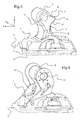
- the heel according to the embodiment of the invention comprises a tubular body 21 movable around a carriage 1 adapted for mounting on a ski, via slides 2 provided on the side portions of the lower base 3 of the carriage, to allow the adjustment of its longitudinal position on a ski to adapt it to different sizes of shoes.
- the movable tubular body 21 comprises in its front part a jaw or "bale grab" 22 adapted for the right-of-way of the normalized sidewalk of a ski boot.
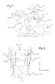
- the movable body 21, more particularly visible on the Figures 3, 4 and 9 comprises within it a triggering mechanism that allows the automatic passage of the heel of the closed ski practice position configuration, shown in FIG. figure 1 , in the open configuration shown in figure 2 , in which the ski boot can escape the heel grip.
- This triggering is automatically implemented in case of skier's fall causing a force on the jaw greater than a predefined threshold.
- the movable body 21 passes from the closed configuration to the open configuration by a rotational movement relative to the carriage 1, about an axis 10.
- the movable body comprises different elements in its interior volume.
- a compression spring 23 bears against the abutment 25 in the upper rear part of the body 21 and bears against a piston 24 at its other end.
- This piston 24 cooperates with a trigger surface provided on the carriage 1, detailed below.
- the triggering threshold can be modified in known manner by modifying the degree of compression of the spring 23 by a set screw 26 positioned at the rear end of the movable body 21 and able to move the abutment 25.
- the moving body 21 and has the particularity of having a large area open 29 down between its jaw 22 and the trigger piston 24, intended to receive the trigger surface of the carriage, as will be detailed later.
- the concept of the invention consists in reinforcing the triggering surface or cam which supports the forces of the movable body by connecting it by two connecting means complementary to the base of the carriage, including at least one reinforcing arm and the body which carries drug.
- This allows to realize the main structure of the triggering surface receiving the most important plastic forces, within a fixed body 4, which we will call “fixed trigger body” 4.
- the fixed trigger body has a volume optimized, representing a compromise between a volume generally sufficient to provide a sufficiently strong structure with an economic material, such as a simple plastic for example, possibly reinforced with glass fibers or any equivalent, and a minimized volume to allow a satisfactory tilting of the movable body and easy donning and a push forward of a satisfactory shoe.
- This solution is less expensive than the solutions of the state of the art that require the use of a metal part.
- the carriage 1, particularly visible on the Figures 5 to 8 comprises a fixed trigger body 4 which is a monolithic central part, in a single body, which extends from the base 3 of the carriage near the surface of the ski to the highest part of the carriage , and over a large width of the carriage, measured along the y direction.
- This central fixed body 4 comprises a substantially cylindrical upper portion 5 oriented transversely to the heel piece, comprising a transverse tubular opening 6 intended to receive the connecting pin 10 with the movable body 21.
- the upper part 5 comprises in its rear part a zone deviating from the cylindrical shape, forming a ramp 7 which performs the trigger function in cooperation with the piston 24 of the tubular body 21, as will be detailed later.
- the ramp 7 extends transversely over the entire width of the central body 4, parallel to the transverse opening 6 in the y direction, and has a substantially triangular section, with a vertex 8 surrounded by two slopes respectively upper 9 and lower 9 ' .
- This upper part 5 is directly connected to the base 3 by a lower portion of the fixed body 4, which extends over the entire width of the upper portion 5 and has a relatively narrow area of small dimension in the longitudinal direction x.
- the body 4 represents a first means of connecting and supporting the surface of the ramp 7.
- this narrower zone comprises a minimum dimension L about 11 millimeters, illustrated on the figure 5 .
- Providing a narrow trigger body 4 in the lower part disposed under the triggering ramp 7 is advantageous since this has the effect of a small footprint facilitating the establishment of the movement of the movable body 21, allowing the definition of a ramp Triggering the booting phases and release of the heel while performing a function of tripping performance. More generally, a minimum dimension of this body in the longitudinal direction x of between 8 and 14 millimeters is advantageous. With such a geometry, the moving body reaches an amplitude of rotation greater than 70 degrees.
- the moving body is therefore provided with a rotation amplitude of 73 degrees between its two extreme positions.
- a reinforcing rib can be arranged between the lower slope 9 'of the ramp 7 and the narrow part of the lower part of the fixed body 4.
- the carriage 1 further comprises two side-mounted arms 11 comprising in their upper part openings 12 for the reception of the connecting shaft 10 which extends transversely of an arm towards the other through the opening 6 arranged in the fixed central body 4 and through openings 27 arranged on two lower lateral wings 28 of the movable body 21, visible on the figure 9 , which are positioned in the space 13 provided between the arms 11 and the central body 4 of the carriage 1.
- These attached arms 11 may be in the same material as the body 4, plastic, optionally reinforced with fibers or metal parts. In a variant, the arms 11 may be made entirely of metal. They are fixed to the base 3 of the carriage 1 in their lower part by screws. Alternatively, any fastening means may be suitable, as a clipping, gluing ... According to yet another variant, the arms could form the same element with the base and / or the trigger body, obtained by molding.
- the operation of the heel is particularly visible on Figures 3 and 4 .
- the heel is in closed configuration, the piston 24 is held in abutment on the upper slope 9 of the ramp 7, stably.
- the piston 24 is pushed back until it reaches the top 8 of the ramp 7, to finally switch to the lower slope 9 'of the ramp 7, in the second open stable position shown on the figure 4 .
- the triggering surface on the carriage has been illustrated via a ramp 7, which provides an advantageous triggering behavior.
- this surface could be different, could alternatively be more generally in the form of any cam surface.
- this trigger surface could have all kinds of dimensions, could for example not occupy the entire width of the trigger body.
- this surface has been shown as extending over the entire width of a central body of the carriage provided between two arms reported.
- the trigger body comprising the triggering surface could have any other geometries, for example no longer be a central body.
- this body has a shape that allows to directly connect the trigger surface positioned in its upper part to the base of the carriage, by a connection means separate from the connecting pin 10 and / or reported arms.
- the trigger body may occupy more than half the width of the heel to present a volume to achieve great strength.
- the trigger body will advantageously have a monolithic shape enabling it to be manufactured by injection or shaping of a plastic material and the triggering surface will occupy a large area so as to have sufficient strength.
- This body may be any rigid plastic, such as polyamide, optionally reinforced with a fiber-based structure.
- the trigger body may be an assembly of several distinct elements, possibly of different materials.
- this body may comprise a high part of plastic material comprising the triggering surface, and a lower part disposed under this surface of tripping so connect directly with the base of the carriage, this lower part can be in any material.
- the shape of the arms reported can be the same different.
- the arms can be positioned in contact with the central fixed body, and no longer delimit a space 13 as in the embodiment shown, the movable body then being positioned outside these reported arms.
- a single reported arm could suffice.
- this arm could be centered, disposed through an opening of the trigger body for example.
- This at least one arm is in the form of an element connected to the base of the carriage and separate from the trigger body, so as to form a reinforcement of the trigger body by supporting a portion of the forces experienced by the surface of the trigger and transmitted via the axis of the moving body. It can have all shapes and sizes allowing it to fulfill this function.
- a carriage for receiving a movable body of a heel of the second family recalled in the preamble comprising a construction in which a base forms its lower part, suitable for connection with a ski, and wherein the triggering surface is directly connected by the trigger body to this base, according to a first connecting means, and is connected in parallel to the base by at least one reinforcing arm, via the mounting axis of the movable body of the heel, according to a second connecting means, the trigger surface and the reinforcing arm being both connected to the axis of the mounting the movable body of the heel.
Landscapes
- Footwear And Its Accessory, Manufacturing Method And Apparatuses (AREA)
Priority Applications (1)
| Application Number | Priority Date | Filing Date | Title |
|---|---|---|---|
| EP11171033A EP2371427A1 (de) | 2008-09-29 | 2009-09-22 | Fersenhalter zur Fixierung für Skischuhe mit beweglichem Körper |
Applications Claiming Priority (1)
| Application Number | Priority Date | Filing Date | Title |
|---|---|---|---|
| FR0856517A FR2936428B1 (fr) | 2008-09-29 | 2008-09-29 | Talonniere de fixation pour chaussure de ski a corps mobile |
Related Child Applications (1)
| Application Number | Title | Priority Date | Filing Date |
|---|---|---|---|
| EP11171033.1 Division-Into | 2011-06-22 |
Publications (2)
| Publication Number | Publication Date |
|---|---|
| EP2168640A1 true EP2168640A1 (de) | 2010-03-31 |
| EP2168640B1 EP2168640B1 (de) | 2012-02-29 |
Family
ID=40524841
Family Applications (2)
| Application Number | Title | Priority Date | Filing Date |
|---|---|---|---|
| EP11171033A Withdrawn EP2371427A1 (de) | 2008-09-29 | 2009-09-22 | Fersenhalter zur Fixierung für Skischuhe mit beweglichem Körper |
| EP09170946A Active EP2168640B1 (de) | 2008-09-29 | 2009-09-22 | Hinterbacken für Skischuhbindung mit beweglichem Körper |
Family Applications Before (1)
| Application Number | Title | Priority Date | Filing Date |
|---|---|---|---|
| EP11171033A Withdrawn EP2371427A1 (de) | 2008-09-29 | 2009-09-22 | Fersenhalter zur Fixierung für Skischuhe mit beweglichem Körper |
Country Status (4)
| Country | Link |
|---|---|
| US (1) | US20100078915A1 (de) |
| EP (2) | EP2371427A1 (de) |
| AT (1) | ATE547158T1 (de) |
| FR (1) | FR2936428B1 (de) |
Cited By (3)
| Publication number | Priority date | Publication date | Assignee | Title |
|---|---|---|---|---|
| FR2952309A1 (fr) * | 2009-11-12 | 2011-05-13 | Salomon Sas | Fixation de securite destinee a etre fixee a un ski munie d'une talonniere |
| EP2527015A1 (de) * | 2011-05-27 | 2012-11-28 | Skis Rossignol | Fersenautomatik für eine Sicherheitsskibindung für Skischuhe |
| FR3133020A1 (fr) * | 2022-02-28 | 2023-09-01 | Skis Rossignol | Dispositif de fixation arrière pour une planche de glisse |
Citations (9)
| Publication number | Priority date | Publication date | Assignee | Title |
|---|---|---|---|---|
| FR2269982A1 (en) * | 1974-02-07 | 1975-12-05 | Salomon & Fils F | Ski boot binding method with pivotal clamp - has rockers maintaining fixed angular clamp position during start of clamping |
| DE3104633A1 (de) * | 1980-03-19 | 1981-12-24 | TMC Corp., 6340 Baar, Zug | "ausloeseskibindung" |
| FR2507095A1 (fr) | 1981-06-06 | 1982-12-10 | Geze Gmbh | Element de fixation de ski |
| US4753452A (en) * | 1982-03-17 | 1988-06-28 | Salomon S.A. | Safety ski binding |
| FR2765115A1 (fr) | 1997-06-26 | 1998-12-31 | Look Fixations Sa | Fixation de securite de chaussure de ski |
| EP0893146A1 (de) | 1997-06-26 | 1999-01-27 | Look Fixations S.A. | Sicherheitsskibindung |
| EP1522334A1 (de) * | 2003-10-10 | 2005-04-13 | Salomon S.A. | Schuhbindung für ein Gleit- oder Rollbrett |
| EP1745827A1 (de) | 2005-04-18 | 2007-01-24 | Look Fixations | Gesicherte Schuhbindung auf einem Gleitbrett |
| EP1900400A1 (de) * | 2006-09-12 | 2008-03-19 | MARKER Deutschland GmbH | Fersenseitiges Schuhhalteraggregat einer Skibindung mit Kulissenbahn als Aussenhülse auf der Schwenkachse |
Family Cites Families (9)
| Publication number | Priority date | Publication date | Assignee | Title |
|---|---|---|---|---|
| FR1294261A (fr) * | 1961-04-13 | 1962-05-26 | Dispositif de fixation de sécurité pour ski | |
| FR2258876B1 (de) * | 1974-01-28 | 1978-02-10 | Salomon & Fils F | |
| FR2321912A1 (fr) * | 1975-08-28 | 1977-03-25 | Salomon & Fils F | Fixation destinee a retenir une chaussure sur un support, notamment un ski ou une plaque montee sur un ski |
| AT369660B (de) * | 1980-11-07 | 1983-01-25 | Tyrolia Freizeitgeraete | Fersenhalter fuer eine sicherheitsskibindung |
| FR2494591B1 (fr) * | 1980-11-27 | 1985-06-28 | Salomon & Fils F | Fixation de securite pour ski |
| FR2575661B1 (fr) * | 1985-01-09 | 1987-03-20 | Salomon Sa | Fixation de securite pour chaussure de ski |
| DE4030816A1 (de) * | 1990-09-28 | 1992-04-02 | Jungkind Roland | Fersenhalterung einer sicherheitsskibindung |
| DE9102427U1 (de) * | 1991-02-28 | 1992-04-02 | Marker Deutschland Gmbh, 8116 Eschenlohe, De | |
| DE102009047821B4 (de) * | 2009-09-30 | 2021-12-16 | Marker Deutschland Gmbh | Gleitbrettbindung mit Montagedeckel |
-
2008
- 2008-09-29 FR FR0856517A patent/FR2936428B1/fr not_active Expired - Fee Related
-
2009
- 2009-09-22 AT AT09170946T patent/ATE547158T1/de active
- 2009-09-22 EP EP11171033A patent/EP2371427A1/de not_active Withdrawn
- 2009-09-22 EP EP09170946A patent/EP2168640B1/de active Active
- 2009-09-28 US US12/568,285 patent/US20100078915A1/en not_active Abandoned
Patent Citations (9)
| Publication number | Priority date | Publication date | Assignee | Title |
|---|---|---|---|---|
| FR2269982A1 (en) * | 1974-02-07 | 1975-12-05 | Salomon & Fils F | Ski boot binding method with pivotal clamp - has rockers maintaining fixed angular clamp position during start of clamping |
| DE3104633A1 (de) * | 1980-03-19 | 1981-12-24 | TMC Corp., 6340 Baar, Zug | "ausloeseskibindung" |
| FR2507095A1 (fr) | 1981-06-06 | 1982-12-10 | Geze Gmbh | Element de fixation de ski |
| US4753452A (en) * | 1982-03-17 | 1988-06-28 | Salomon S.A. | Safety ski binding |
| FR2765115A1 (fr) | 1997-06-26 | 1998-12-31 | Look Fixations Sa | Fixation de securite de chaussure de ski |
| EP0893146A1 (de) | 1997-06-26 | 1999-01-27 | Look Fixations S.A. | Sicherheitsskibindung |
| EP1522334A1 (de) * | 2003-10-10 | 2005-04-13 | Salomon S.A. | Schuhbindung für ein Gleit- oder Rollbrett |
| EP1745827A1 (de) | 2005-04-18 | 2007-01-24 | Look Fixations | Gesicherte Schuhbindung auf einem Gleitbrett |
| EP1900400A1 (de) * | 2006-09-12 | 2008-03-19 | MARKER Deutschland GmbH | Fersenseitiges Schuhhalteraggregat einer Skibindung mit Kulissenbahn als Aussenhülse auf der Schwenkachse |
Cited By (5)
| Publication number | Priority date | Publication date | Assignee | Title |
|---|---|---|---|---|
| FR2952309A1 (fr) * | 2009-11-12 | 2011-05-13 | Salomon Sas | Fixation de securite destinee a etre fixee a un ski munie d'une talonniere |
| EP2527015A1 (de) * | 2011-05-27 | 2012-11-28 | Skis Rossignol | Fersenautomatik für eine Sicherheitsskibindung für Skischuhe |
| FR2975604A1 (fr) * | 2011-05-27 | 2012-11-30 | Rossignol Sa | Talonniere de fixation de securite pour chaussure de ski |
| US8820771B2 (en) | 2011-05-27 | 2014-09-02 | Skis Rossignol | Safety fastening heelpiece for ski boot |
| FR3133020A1 (fr) * | 2022-02-28 | 2023-09-01 | Skis Rossignol | Dispositif de fixation arrière pour une planche de glisse |
Also Published As
| Publication number | Publication date |
|---|---|
| EP2168640B1 (de) | 2012-02-29 |
| EP2371427A1 (de) | 2011-10-05 |
| FR2936428B1 (fr) | 2010-10-01 |
| ATE547158T1 (de) | 2012-03-15 |
| FR2936428A1 (fr) | 2010-04-02 |
| US20100078915A1 (en) | 2010-04-01 |
Similar Documents
| Publication | Publication Date | Title |
|---|---|---|
| EP2121422B1 (de) | Fahrradpedal mit automatischer haftung und lösung | |
| EP2687275B1 (de) | Vordere Haltevorrichtungen eines Gleitbrettes | |
| EP1611929A1 (de) | Bindungssystem für ein Gleitbrett mit erleichtertem Ein- und Ausstieg | |
| FR2537442A1 (fr) | Fixation de securite pour ski | |
| EP2168640B1 (de) | Hinterbacken für Skischuhbindung mit beweglichem Körper | |
| CH618095A5 (de) | ||
| EP0769977A1 (de) | Sicherheitsbindung für telemarkskis, tourenskis und sprungskis | |
| EP1008373A1 (de) | Skibindung | |
| EP0760246B1 (de) | Bindungsteil für Ski, Fersenhalter oder Vorderbacken | |
| EP2527015B1 (de) | Fersenautomatik für eine Sicherheitsskibindung für Skischuhe | |
| EP0634197A1 (de) | Bindungselement für einen alpinen Ski | |
| CH673400A5 (de) | ||
| EP0634196A1 (de) | Bindungselement für einen alphinen Ski | |
| EP1104251A1 (de) | Langlaufskischuh | |
| EP0231713B1 (de) | Kombination bestehend aus einem Langlaufski, einer Langlaufbindung und einem Langlaufschuh | |
| CH652936A5 (fr) | Fixation de securite pour ski. | |
| EP2386333B1 (de) | Befestigungselement mit einstellbarer Position auf einem Schneegleitbrett | |
| EP1027908A1 (de) | Rückhaltesystem für Schuhe auf Skier | |
| EP1522334B1 (de) | Schuhbindung für ein Gleit- oder Rollbrett | |
| EP2322255B1 (de) | Bremsvorrichtung für Snowboard | |
| EP1905493B1 (de) | Fersenautomatik zur Fixierung für Skischuhe mit feststehendem Körper | |
| EP3564108B1 (de) | Fahrradpedal mit schuhplatteneingriffselement | |
| EP2578277B1 (de) | Fersenautomatik für eine Sicherheitsskibindung für Skischuhe | |
| FR3072884A1 (fr) | Butee de dispositif de fixation d'une chaussure | |
| EP0193687B1 (de) | Rückhaltevorrichtung für einen Schuh auf einem Ski |
Legal Events
| Date | Code | Title | Description |
|---|---|---|---|
| PUAI | Public reference made under article 153(3) epc to a published international application that has entered the european phase |
Free format text: ORIGINAL CODE: 0009012 |
|
| AK | Designated contracting states |
Kind code of ref document: A1 Designated state(s): AT BE BG CH CY CZ DE DK EE ES FI FR GB GR HR HU IE IS IT LI LT LU LV MC MK MT NL NO PL PT RO SE SI SK SM TR |
|
| AX | Request for extension of the european patent |
Extension state: AL BA RS |
|
| 17P | Request for examination filed |
Effective date: 20100719 |
|
| 17Q | First examination report despatched |
Effective date: 20100817 |
|
| RIC1 | Information provided on ipc code assigned before grant |
Ipc: A63C 9/084 20060101AFI20110527BHEP |
|
| GRAP | Despatch of communication of intention to grant a patent |
Free format text: ORIGINAL CODE: EPIDOSNIGR1 |
|
| GRAS | Grant fee paid |
Free format text: ORIGINAL CODE: EPIDOSNIGR3 |
|
| RAP1 | Party data changed (applicant data changed or rights of an application transferred) |
Owner name: SKIS ROSSIGNOL |
|
| GRAA | (expected) grant |
Free format text: ORIGINAL CODE: 0009210 |
|
| AK | Designated contracting states |
Kind code of ref document: B1 Designated state(s): AT BE BG CH CY CZ DE DK EE ES FI FR GB GR HR HU IE IS IT LI LT LU LV MC MK MT NL NO PL PT RO SE SI SK SM TR |
|
| REG | Reference to a national code |
Ref country code: GB Ref legal event code: FG4D Free format text: NOT ENGLISH Ref country code: CH Ref legal event code: EP |
|
| REG | Reference to a national code |
Ref country code: AT Ref legal event code: REF Ref document number: 547158 Country of ref document: AT Kind code of ref document: T Effective date: 20120315 |
|
| REG | Reference to a national code |
Ref country code: IE Ref legal event code: FG4D Free format text: LANGUAGE OF EP DOCUMENT: FRENCH |
|
| REG | Reference to a national code |
Ref country code: DE Ref legal event code: R096 Ref document number: 602009005594 Country of ref document: DE Effective date: 20120503 |
|
| REG | Reference to a national code |
Ref country code: NL Ref legal event code: VDEP Effective date: 20120229 |
|
| LTIE | Lt: invalidation of european patent or patent extension |
Effective date: 20120229 |
|
| PG25 | Lapsed in a contracting state [announced via postgrant information from national office to epo] |
Ref country code: LT Free format text: LAPSE BECAUSE OF FAILURE TO SUBMIT A TRANSLATION OF THE DESCRIPTION OR TO PAY THE FEE WITHIN THE PRESCRIBED TIME-LIMIT Effective date: 20120229 Ref country code: IS Free format text: LAPSE BECAUSE OF FAILURE TO SUBMIT A TRANSLATION OF THE DESCRIPTION OR TO PAY THE FEE WITHIN THE PRESCRIBED TIME-LIMIT Effective date: 20120629 Ref country code: NL Free format text: LAPSE BECAUSE OF FAILURE TO SUBMIT A TRANSLATION OF THE DESCRIPTION OR TO PAY THE FEE WITHIN THE PRESCRIBED TIME-LIMIT Effective date: 20120229 Ref country code: HR Free format text: LAPSE BECAUSE OF FAILURE TO SUBMIT A TRANSLATION OF THE DESCRIPTION OR TO PAY THE FEE WITHIN THE PRESCRIBED TIME-LIMIT Effective date: 20120229 Ref country code: NO Free format text: LAPSE BECAUSE OF FAILURE TO SUBMIT A TRANSLATION OF THE DESCRIPTION OR TO PAY THE FEE WITHIN THE PRESCRIBED TIME-LIMIT Effective date: 20120529 |
|
| PG25 | Lapsed in a contracting state [announced via postgrant information from national office to epo] |
Ref country code: LV Free format text: LAPSE BECAUSE OF FAILURE TO SUBMIT A TRANSLATION OF THE DESCRIPTION OR TO PAY THE FEE WITHIN THE PRESCRIBED TIME-LIMIT Effective date: 20120229 Ref country code: PT Free format text: LAPSE BECAUSE OF FAILURE TO SUBMIT A TRANSLATION OF THE DESCRIPTION OR TO PAY THE FEE WITHIN THE PRESCRIBED TIME-LIMIT Effective date: 20120629 Ref country code: GR Free format text: LAPSE BECAUSE OF FAILURE TO SUBMIT A TRANSLATION OF THE DESCRIPTION OR TO PAY THE FEE WITHIN THE PRESCRIBED TIME-LIMIT Effective date: 20120530 Ref country code: FI Free format text: LAPSE BECAUSE OF FAILURE TO SUBMIT A TRANSLATION OF THE DESCRIPTION OR TO PAY THE FEE WITHIN THE PRESCRIBED TIME-LIMIT Effective date: 20120229 |
|
| REG | Reference to a national code |
Ref country code: AT Ref legal event code: MK05 Ref document number: 547158 Country of ref document: AT Kind code of ref document: T Effective date: 20120229 |
|
| REG | Reference to a national code |
Ref country code: IE Ref legal event code: FD4D |
|
| PG25 | Lapsed in a contracting state [announced via postgrant information from national office to epo] |
Ref country code: CY Free format text: LAPSE BECAUSE OF FAILURE TO SUBMIT A TRANSLATION OF THE DESCRIPTION OR TO PAY THE FEE WITHIN THE PRESCRIBED TIME-LIMIT Effective date: 20120229 |
|
| PG25 | Lapsed in a contracting state [announced via postgrant information from national office to epo] |
Ref country code: EE Free format text: LAPSE BECAUSE OF FAILURE TO SUBMIT A TRANSLATION OF THE DESCRIPTION OR TO PAY THE FEE WITHIN THE PRESCRIBED TIME-LIMIT Effective date: 20120229 Ref country code: RO Free format text: LAPSE BECAUSE OF FAILURE TO SUBMIT A TRANSLATION OF THE DESCRIPTION OR TO PAY THE FEE WITHIN THE PRESCRIBED TIME-LIMIT Effective date: 20120229 Ref country code: SI Free format text: LAPSE BECAUSE OF FAILURE TO SUBMIT A TRANSLATION OF THE DESCRIPTION OR TO PAY THE FEE WITHIN THE PRESCRIBED TIME-LIMIT Effective date: 20120229 Ref country code: PL Free format text: LAPSE BECAUSE OF FAILURE TO SUBMIT A TRANSLATION OF THE DESCRIPTION OR TO PAY THE FEE WITHIN THE PRESCRIBED TIME-LIMIT Effective date: 20120229 Ref country code: CZ Free format text: LAPSE BECAUSE OF FAILURE TO SUBMIT A TRANSLATION OF THE DESCRIPTION OR TO PAY THE FEE WITHIN THE PRESCRIBED TIME-LIMIT Effective date: 20120229 Ref country code: SE Free format text: LAPSE BECAUSE OF FAILURE TO SUBMIT A TRANSLATION OF THE DESCRIPTION OR TO PAY THE FEE WITHIN THE PRESCRIBED TIME-LIMIT Effective date: 20120229 Ref country code: DK Free format text: LAPSE BECAUSE OF FAILURE TO SUBMIT A TRANSLATION OF THE DESCRIPTION OR TO PAY THE FEE WITHIN THE PRESCRIBED TIME-LIMIT Effective date: 20120229 Ref country code: IE Free format text: LAPSE BECAUSE OF FAILURE TO SUBMIT A TRANSLATION OF THE DESCRIPTION OR TO PAY THE FEE WITHIN THE PRESCRIBED TIME-LIMIT Effective date: 20120229 |
|
| PG25 | Lapsed in a contracting state [announced via postgrant information from national office to epo] |
Ref country code: SK Free format text: LAPSE BECAUSE OF FAILURE TO SUBMIT A TRANSLATION OF THE DESCRIPTION OR TO PAY THE FEE WITHIN THE PRESCRIBED TIME-LIMIT Effective date: 20120229 Ref country code: IT Free format text: LAPSE BECAUSE OF FAILURE TO SUBMIT A TRANSLATION OF THE DESCRIPTION OR TO PAY THE FEE WITHIN THE PRESCRIBED TIME-LIMIT Effective date: 20120229 |
|
| PLBE | No opposition filed within time limit |
Free format text: ORIGINAL CODE: 0009261 |
|
| STAA | Information on the status of an ep patent application or granted ep patent |
Free format text: STATUS: NO OPPOSITION FILED WITHIN TIME LIMIT |
|
| PG25 | Lapsed in a contracting state [announced via postgrant information from national office to epo] |
Ref country code: AT Free format text: LAPSE BECAUSE OF FAILURE TO SUBMIT A TRANSLATION OF THE DESCRIPTION OR TO PAY THE FEE WITHIN THE PRESCRIBED TIME-LIMIT Effective date: 20120229 |
|
| 26N | No opposition filed |
Effective date: 20121130 |
|
| REG | Reference to a national code |
Ref country code: DE Ref legal event code: R097 Ref document number: 602009005594 Country of ref document: DE Effective date: 20121130 |
|
| BERE | Be: lapsed |
Owner name: SKIS ROSSIGNOL Effective date: 20120930 |
|
| PG25 | Lapsed in a contracting state [announced via postgrant information from national office to epo] |
Ref country code: ES Free format text: LAPSE BECAUSE OF FAILURE TO SUBMIT A TRANSLATION OF THE DESCRIPTION OR TO PAY THE FEE WITHIN THE PRESCRIBED TIME-LIMIT Effective date: 20120609 Ref country code: MC Free format text: LAPSE BECAUSE OF NON-PAYMENT OF DUE FEES Effective date: 20120930 |
|
| PG25 | Lapsed in a contracting state [announced via postgrant information from national office to epo] |
Ref country code: BG Free format text: LAPSE BECAUSE OF FAILURE TO SUBMIT A TRANSLATION OF THE DESCRIPTION OR TO PAY THE FEE WITHIN THE PRESCRIBED TIME-LIMIT Effective date: 20120529 Ref country code: BE Free format text: LAPSE BECAUSE OF NON-PAYMENT OF DUE FEES Effective date: 20120930 |
|
| PG25 | Lapsed in a contracting state [announced via postgrant information from national office to epo] |
Ref country code: MT Free format text: LAPSE BECAUSE OF FAILURE TO SUBMIT A TRANSLATION OF THE DESCRIPTION OR TO PAY THE FEE WITHIN THE PRESCRIBED TIME-LIMIT Effective date: 20120229 |
|
| PG25 | Lapsed in a contracting state [announced via postgrant information from national office to epo] |
Ref country code: TR Free format text: LAPSE BECAUSE OF FAILURE TO SUBMIT A TRANSLATION OF THE DESCRIPTION OR TO PAY THE FEE WITHIN THE PRESCRIBED TIME-LIMIT Effective date: 20120229 |
|
| REG | Reference to a national code |
Ref country code: CH Ref legal event code: PL |
|
| GBPC | Gb: european patent ceased through non-payment of renewal fee |
Effective date: 20130922 |
|
| PG25 | Lapsed in a contracting state [announced via postgrant information from national office to epo] |
Ref country code: LU Free format text: LAPSE BECAUSE OF NON-PAYMENT OF DUE FEES Effective date: 20120922 Ref country code: SM Free format text: LAPSE BECAUSE OF FAILURE TO SUBMIT A TRANSLATION OF THE DESCRIPTION OR TO PAY THE FEE WITHIN THE PRESCRIBED TIME-LIMIT Effective date: 20120229 |
|
| PG25 | Lapsed in a contracting state [announced via postgrant information from national office to epo] |
Ref country code: GB Free format text: LAPSE BECAUSE OF NON-PAYMENT OF DUE FEES Effective date: 20130922 Ref country code: CH Free format text: LAPSE BECAUSE OF NON-PAYMENT OF DUE FEES Effective date: 20130930 Ref country code: HU Free format text: LAPSE BECAUSE OF FAILURE TO SUBMIT A TRANSLATION OF THE DESCRIPTION OR TO PAY THE FEE WITHIN THE PRESCRIBED TIME-LIMIT Effective date: 20090922 Ref country code: LI Free format text: LAPSE BECAUSE OF NON-PAYMENT OF DUE FEES Effective date: 20130930 |
|
| PG25 | Lapsed in a contracting state [announced via postgrant information from national office to epo] |
Ref country code: MK Free format text: LAPSE BECAUSE OF FAILURE TO SUBMIT A TRANSLATION OF THE DESCRIPTION OR TO PAY THE FEE WITHIN THE PRESCRIBED TIME-LIMIT Effective date: 20120229 |
|
| REG | Reference to a national code |
Ref country code: FR Ref legal event code: PLFP Year of fee payment: 7 |
|
| REG | Reference to a national code |
Ref country code: FR Ref legal event code: PLFP Year of fee payment: 8 |
|
| REG | Reference to a national code |
Ref country code: FR Ref legal event code: PLFP Year of fee payment: 9 |
|
| REG | Reference to a national code |
Ref country code: FR Ref legal event code: PLFP Year of fee payment: 10 |
|
| PGFP | Annual fee paid to national office [announced via postgrant information from national office to epo] |
Ref country code: DE Payment date: 20190927 Year of fee payment: 11 |
|
| REG | Reference to a national code |
Ref country code: DE Ref legal event code: R119 Ref document number: 602009005594 Country of ref document: DE |
|
| PG25 | Lapsed in a contracting state [announced via postgrant information from national office to epo] |
Ref country code: DE Free format text: LAPSE BECAUSE OF NON-PAYMENT OF DUE FEES Effective date: 20210401 |
|
| PGFP | Annual fee paid to national office [announced via postgrant information from national office to epo] |
Ref country code: FR Payment date: 20230925 Year of fee payment: 15 |