EP1522334B1 - Schuhbindung für ein Gleit- oder Rollbrett - Google Patents
Schuhbindung für ein Gleit- oder Rollbrett Download PDFInfo
- Publication number
- EP1522334B1 EP1522334B1 EP04023878A EP04023878A EP1522334B1 EP 1522334 B1 EP1522334 B1 EP 1522334B1 EP 04023878 A EP04023878 A EP 04023878A EP 04023878 A EP04023878 A EP 04023878A EP 1522334 B1 EP1522334 B1 EP 1522334B1
- Authority
- EP
- European Patent Office
- Prior art keywords
- arms
- shoe
- base
- lever
- boot
- Prior art date
- Legal status (The legal status is an assumption and is not a legal conclusion. Google has not performed a legal analysis and makes no representation as to the accuracy of the status listed.)
- Expired - Lifetime
Links
- 230000027455 binding Effects 0.000 title description 3
- 238000009739 binding Methods 0.000 title description 3
- 238000005096 rolling process Methods 0.000 claims description 3
- 230000000750 progressive effect Effects 0.000 claims 1
- 238000010276 construction Methods 0.000 description 7
- 210000003127 knee Anatomy 0.000 description 3
- 230000002747 voluntary effect Effects 0.000 description 3
- 230000000295 complement effect Effects 0.000 description 2
- 239000002184 metal Substances 0.000 description 2
- 210000002445 nipple Anatomy 0.000 description 2
- 208000031968 Cadaver Diseases 0.000 description 1
- 238000006243 chemical reaction Methods 0.000 description 1
- 238000006073 displacement reaction Methods 0.000 description 1
- 230000005489 elastic deformation Effects 0.000 description 1
- 210000000629 knee joint Anatomy 0.000 description 1
- 230000014759 maintenance of location Effects 0.000 description 1
- 239000000463 material Substances 0.000 description 1
- 238000000034 method Methods 0.000 description 1
- 230000000452 restraining effect Effects 0.000 description 1
- 230000000717 retained effect Effects 0.000 description 1
- 230000000630 rising effect Effects 0.000 description 1
- 239000011435 rock Substances 0.000 description 1
- 230000007704 transition Effects 0.000 description 1
- 230000001960 triggered effect Effects 0.000 description 1
- 230000021542 voluntary musculoskeletal movement Effects 0.000 description 1
Images


Classifications
-
- A—HUMAN NECESSITIES
- A63—SPORTS; GAMES; AMUSEMENTS
- A63C—SKATES; SKIS; ROLLER SKATES; DESIGN OR LAYOUT OF COURTS, RINKS OR THE LIKE
- A63C7/00—Devices preventing skis from slipping back; Ski-stoppers or ski-brakes
- A63C7/10—Hinged stoppage blades attachable to the skis in such manner that these blades can be moved out of the operative position
- A63C7/1006—Ski-stoppers
- A63C7/1013—Ski-stoppers actuated by the boot
Definitions
- the invention relates to a retaining element of a shoe on a gliding or rolling board.
- the invention relates to a non-releasable retaining element, that is to say, which does not itself ensure the release of the shoe in case of excessive stress.
- a releasable restraint is described in the document FR 2368973 .
- the release mechanism is housed in a body pivotally mounted on an axis carried by two arms.
- the invention applies in particular but not exclusively to the ski area where it is common to attach a shoe on the board by a front retainer and a rear retainer, each of these elements holding a tip of the shoe.
- the most common device for retaining non-releasably the tip of a shoe consists of a stirrup whose two ends are brought under the shoe sole
- a stirrup whose two ends are brought under the shoe sole
- the rear caliper is equipped with a lever for the voluntary attachment of the shoe on the gliding board and its stall.
- US 4,168,084 also discloses such a device arranged only for the back of the shoe.
- the invention proposes a retaining element which comprises a base having a support plate provided for receiving a shoe sole, a body provided with a retaining jaw provided for retaining a shoe tip, the body being connected. at the base by two arms link, and being pivotally connected to these arms about an upper axis of transverse articulation, each arm being connected to the base by a hinge about a lower axis of articulation transverse, the jaw being movable between a retaining position where it is able to retain the tip of the shoe and a release position where the shoe tip can escape, the connecting arms and the body forming a toggle joint closed in the jaw retainer position and open in the release position.
- the retaining element is characterized in that at least in the closed position of the toggle joint, a. elastic element resiliently recalls at least one of the elements that are the arms and the body to the open position of the toggle.
- the knee joint formed by the arms and the body is elastically extensible to facilitate the closure of the knee during the introduction of the shoe.
- an articulated pedal actuable by the shoe controls a lever for tilting the body in its retaining position.
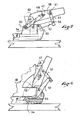
- the figure 1 shows a portion of gliding board 1 on which rests the rear end of a shoe 2.
- the rear end comprises a tip 3 with an upper flange 4.
- the rear end is retained on the gliding board 1 by a retaining member 5 which will now be described.
- This element comprises a base 6 with an upper support plate 7 provided for receiving the shoe sole.
- the base is assembled directly to the ski, or it is slidably mounted in the longitudinal direction defined by the ski. Possibly the base can slide backwards from a defined longitudinal position by compressing a return spring.
- a return spring Such a method of construction is known in the field of ski bindings.
- a ski brake 8 is associated with the base.
- the brake comprises a bearing 9 which is assembled to the base and an actuating pedal connected to the bearing by a return spring and metal wires which extend beyond the bearing to form the braking arms 11 and 12.
- the construction of such a brake is known and will not be described in more detail.
- the brake is optional.
- the base comprises a rising wall 14 which bypasses the rear end of the shoe sole and forming with the support plate 7 a housing for the shoe heel.
- This wall is however optional.
- the element 5 further comprises a retaining body 16 having in its lower part a jaw 17 which holds the boot.
- the jaw has two studs symmetrical with respect to a longitudinal and vertical median plane. Both nipples rest on the rim 4 of the rear shoe tip. The two nipples frame the rear end of the shoe thus ensuring its centering with respect to the restraining element.
- Other solutions may also be appropriate. Especially one could have a continuous jaw shaped crescent.
- the body 16 is mounted in free rotation around a horizontal and transverse axis 18.
- the axis 18 is carried by two arms 20 and 21 whose lower ends are connected to the base 6 by a hinge pin, respectively 22 and 23.
- the shafts 22 and 23 are mounted in the parts of the wall 14 which are oriented parallel to the longitudinal direction defined by the ski.
- the arms can pivot freely about these axes 22 and 23. In the retaining position which is shown in FIG. figure 1 , the arms are oriented in an oblique direction upwards and backwards.
- the assembly formed by the base, the arms, the body and their axes of articulation operates in the manner of a toggle.
- the jaw 17 In the position represented in figure 1 , the jaw 17 is located below the alignment of the axes 22-23, 18, that is to say downward and rearward relative to this alignment.
- the expression "22-23" designates the common axis of the two articulation axes 22 and 23 viewed from the side. As a result, a vertical upward force exerted by the shoe on the jaw tends to bring the arms towards the shoe. Under these conditions, the toggle is in a closed stable position and the retaining element is in the retaining position of the boot.
- the jaw is placed on the tip of the boot, then the upper end of the body is tilted towards the boot upper to close the toggle.
- one of the two axes 22-23 or 18 is mounted with play being elastically biased towards the shoe.
- the shaft 18 is slidably mounted in a lumen 25 of the body.
- the light is oriented in the longitudinal direction of the body and the axis 18 is elastically biased towards the top of the light, that is to say towards the upper end of the body by a spring 26 or a battery of springs placed in parallel.
- the body 16 has a shouldered housing 28 provided for a sliding drawer 27 which is traversed by the axis 18 and for the spring 26.
- One end of the spring bears against one shoulder of the housing and the other end bears against a washer 31 which is traversed by a clamping screw 30 which is screwed into the spool 27. In this way it is possible to adjust the restoring force which is exerted by the spring on the spindle 18 in its slot 25.
- the arms are made of metal and are shaped by folding, their ends being further apart on the side of the base that the side of the body. In this way, by varying the thickness of the material, the desired longitudinal clearance can be obtained by an elastic deformation of the arms.
- the retaining element 5 is provided to cooperate with a complementary element that holds the other end of the shoe.
- This element is of the type with voluntary opening or opening triggered by the level of stresses to which the shoe subjects the binding.
- the body of the retaining element 5 flips on its own to facilitate the release of the boot.
- at least one of the components that are the arms and the body of the rear retention element are biased towards the board 1 by a spring or the like which exerts on the component a reduced intensity return force.
- each of the arms 20 and 21 is biased backwards by a small wire spring 32, 33 one end (not visible) is embedded in the base 6, and the other end 32a, 33a is attached to each of the arms.
- the springs 32 and 33 urge the toggle in the direction of its opening. This occurs effortlessly as soon as the shoe is no longer held by the other end. A minimal displacement of the shoe is sufficient for the springs 32 and 33 bring the knee lever in an unstable position. Once this position is reached, the efforts that the shoe exerts if necessary on the jaw lead to its total tilting so as to release the shoe. Without the presence of the springs there would be a risk that the toggle does not open because the rear end of the shoe biases the jaw in a direction that keeps it in its stable position.
- springs 32 and 33 could be provided with return springs between the arms 20, 21 and the body 16. It could also be placed a resilient return element between the body 16 and the base 6, the important thing being exert on one of the components of the toggle a reduced return force in the unstable position of the toggle.
- the retaining element 5 can be closed by placing the jaw on the rim of the shoe and tilting the body towards the shoe shank as previously mentioned.
- the general idea is to place under the shoe sole an articulated foot pedal which is linked with the body. By pressing the pedal the shoe forces the body to switch to the closed position of the toggle as it engages in the retainer.
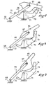
- the element represented in figure 4 comprises as the previous a body 47 connected to a base 46 by two arms, only the arm 48 being visible, with hinge pins 49 and 50.
- the arms 48 and / or the body 47 are biased backwards by a resilient return device of low stiffness, such as for example the spring 51 shown in the figures.
- this or these springs elastically recall the body in the release position of the shoe which is illustrated in FIG. figure 4 . This position is also a waiting position of the shoe.
- a lever 52 is articulated to the base around an axis 53 located on the rear of the base.
- One end 54 of the lever is under the back of the shoe sole when the boot is engaged in the retainer. This end forms the foot pedal on which the shoe is supported. This end is preferably curved upwards.
- the other end 55 of the lever is connected to a link 57 by a hinge 56, and the rod is itself connected to the body 47 about an axis 58 which is located opposite the jaw 60 with respect to the axis 49.
- one of the pins 56 or 58 is mounted with clearance.
- figure 4 it is the connection between the axis 58 and the rod 57 which has play because the axis 58 is mounted in a longitudinal slot 61 of the rod.
- the length of the lever 52, the rod 57 and the position of the axes 53, 56 and 58 makes that in the waiting position of the boot, the foot pedal 54 is raised above the support plate of the shoe.
- the support of the shoe on the pedal 54 causes the lever 52 to tilt as shown in FIG. figure 5 .
- the rod 57 exerts on the body an upward thrust that tilts the body 47 about the axis 49 until the jaw 60 comes into contact with the shoe. This position is illustrated in the figure 5 .
- the rod forces the body to rock, the body acts by reaction on the arms 48 which forces the toggle switch to a stable position of closure.
- This position is illustrated in the figure 6 .
- the light 60 which is in the body and the elastic return of the axis 49 in this light facilitate the passage of the knee to its closed position.
- the light 61 in the rod 57 also facilitates this transition.
- the pedal 54 is preferably retracted into a housing 64 of the base.
- the figure 6 shows the body in this holding position of the shoe.
- lever could act simply by pushing on the body, in particular by cooperation of evolutive ramps between the lever and the body.
- the retaining element comprises a body 65 hinged to arms 66 about an axis 67, the arms themselves being articulated to the base around an axis 68.
- a lever 70 is pivotally mounted about an axis 71 mounted on the base.
- the lever comprises a front pedal 72 and on the rear of the other side of the axis 71 a ramp 73 which is provided to cooperate with a ramp 74 of the body facing the ramp 73.
- the ramps cooperate in an evolutionary manner, that is to say that their respective contact point moves as the lever tilts.
- the contact zone is located towards the end of the lever opposite the pedal 72, this causes the first phase of tilting of the body. Then the contact zone moves in a hollow zone of the ramp 74 cooperating with a ventrue zone of the ramp 73 to cause the tilting of the arms until the closure of the toggle.
- the retainer just described is intended to be used in combination with any other suitable retainer.
- it may be a stirrup-type element with a manual lever for voluntary opening, or a retaining element with trigger whose jaw opens in case of excessive stress exerted by the shoe and remains in this open position a sufficient time to allow the shoe to disengage itself. It can be mounted on a ski, a short ski, a snowboard or generally on any snowboard or rolling.
- the retaining element could be used to retain the front end of the shoe.
Landscapes
- Footwear And Its Accessory, Manufacturing Method And Apparatuses (AREA)
- Lubricants (AREA)
- Closing And Opening Devices For Wings, And Checks For Wings (AREA)
- Braking Arrangements (AREA)
Claims (8)
- Element zur Bindung eines Schuhs auf einem Gleit- oder Rollbrett, das im Falle einer übermäßigen Beanspruchung den Schuh nicht von alleine freigibt und Folgendes umfasst: eine Basis (6, 46) mit einer Stützplatte (14), die zur Aufnahme einer Schuhsohle vorgesehen ist, einen Körper (16, 47, 65), der mit einer Klemmbacke (17, 60) versehen ist, die zum Festhalten einer Zehenkappe des Schuhs vorgesehen ist, wobei der Körper (16, 47, 65) durch zwei Verbindungsarme (20, 21, 48, 66) mit der Basis verbunden ist und so mit diesen Armen verbunden ist, dass er um einen oberen Quergelenkzapfen (18, 49, 67) schwenken kann, wobei jeder dieser Arme durch ein Gelenk um einen unteren Quergelenkzapfen (22 - 23, 50, 68) mit der Basis verbunden ist, wobei die Klemmbacke zwischen einer Halteposition, in der sie in der Lage ist, die Zehenkappe des Schuhs festzuhalten, und einer Freigabeposition, in der die Zehenkappe des Schuhs herausgenommen werden kann, beweglich ist, wobei die Verbindungsarme und der Körper ein Kniegelenk bilden, das in der Halteposition der Klemmbacke geschlossen ist und in der Freigabeposition geöffnet ist, dadurch gekennzeichnet, dass zumindest in der geschlossenen Position des Kniegelenks ein elastisches Element (32, 33, 51) mindestens eine der Komponenten von den Armen (20, 21, 48, 66) und dem Körper (16, 47, 65) in die geöffnete Position des Kniegelenks elastisch zurückholt, dass es ein angelenktes Einstiegspedal (54, 72) umfasst, das mit dem Körper (47, 65) dahingehend zusammenwirkt, das Kippen des Körpers in die geschlossene Position des Kniegelenks zu bewirken, und dass das Einstiegspedal (54, 72) das Ende eines um einen an der Basis (46) vorgesehenen Querzapfen (53, 71) angelenkten Hebels (52, 70) ist und der Teil des Hebels, der dem Pedal bezüglich seinem Zapfen gegenüberliegt, durch eine Verbindung mit dem Körper verbunden ist.
- Element nach Anspruch 1, dadurch gekennzeichnet, dass es ein elastisches Rückholelement zwischen dem Körper (16) und der Basis (6) aufweist.
- Element nach Anspruch 1, dadurch gekennzeichnet, dass jeder der Arme (20, 21) durch eine kleine Drahtfeder (32, 33), von der ein Ende in der Basis (6) eingebettet ist und das andere Ende (32a, 33a) an jedem der Arme festgehakt ist, nach hinten zurückgeholt wird.
- Element nach Anspruch 1, dadurch gekennzeichnet, dass es ein elastisches Rückholelement zwischen den Armen (20, 21) und dem Körper (16) aufweist.
- Element nach Anspruch 1, dadurch gekennzeichnet, dass der Zapfen (18), der den Körper (16) an den Armen (20, 21) anlenkt, in einer Ausnehmung (25) des Körpers in Ausrichtung zur Längsrichtung des Körpers angebracht ist, und dass eine Rückholfeder (26) den Zapfen (18) zu einem Ende der Ausnehmung elastisch drückt.
- Element nach Anspruch 3, dadurch gekennzeichnet, dass der Körper (16) eine mit Schultern versehene Aufnahme (28) aufweist, die für einen Gleitschieber (27), die von dem Zapfen (18) durchquert wird, und für die Feder (26) bestimmt ist, und dass ein Ende der Feder an einer Schulter der Aufnahme anliegt und das andere Ende an einer Klemmschraube (30) anliegt, die in den Gleitschieber (27) geschraubt ist.
- Element nach Anspruch 1, dadurch gekennzeichnet, dass der Hebel (52) durch eine auf einer Seite am Hebel (52) und auf der anderen am Körper (47) angelenkte Stange (57) mit dem Körper (47) zusammenwirkt.
- Element nach Anspruch 1, dadurch gekennzeichnet, dass der Hebel (70) durch zwei verlaufsveränderliche Rampen (73, 74) des Körpers und des Hebels mit dem Körper (65) zusammenwirkt.
Applications Claiming Priority (2)
| Application Number | Priority Date | Filing Date | Title |
|---|---|---|---|
| FR0311900 | 2003-10-10 | ||
| FR0311900A FR2860729B1 (fr) | 2003-10-10 | 2003-10-10 | Element de retenue d'une chaussure sur une planche de glisse ou de roulage |
Publications (2)
| Publication Number | Publication Date |
|---|---|
| EP1522334A1 EP1522334A1 (de) | 2005-04-13 |
| EP1522334B1 true EP1522334B1 (de) | 2010-09-15 |
Family
ID=34307529
Family Applications (1)
| Application Number | Title | Priority Date | Filing Date |
|---|---|---|---|
| EP04023878A Expired - Lifetime EP1522334B1 (de) | 2003-10-10 | 2004-10-07 | Schuhbindung für ein Gleit- oder Rollbrett |
Country Status (4)
| Country | Link |
|---|---|
| EP (1) | EP1522334B1 (de) |
| AT (1) | ATE481142T1 (de) |
| DE (1) | DE602004029126D1 (de) |
| FR (1) | FR2860729B1 (de) |
Families Citing this family (4)
| Publication number | Priority date | Publication date | Assignee | Title |
|---|---|---|---|---|
| SE9803384L (sv) | 1998-03-02 | 1999-09-03 | Kemira Kemi Ab | Förfarande för behandling av processvatten |
| FR2909761B1 (fr) | 2006-12-11 | 2009-03-13 | Salomon Sa | Procede de controle de la liaison entre un individu et son engin de glisse ou de roulage et dispositif pour la mise en oeuvre du procede |
| FR2936428B1 (fr) * | 2008-09-29 | 2010-10-01 | Rossignol Sa | Talonniere de fixation pour chaussure de ski a corps mobile |
| AT513694B1 (de) * | 2012-12-07 | 2015-11-15 | Gattinger Erwin | Skibindung für Kurzskier |
Family Cites Families (7)
| Publication number | Priority date | Publication date | Assignee | Title |
|---|---|---|---|---|
| DE1428883A1 (de) * | 1964-07-08 | 1969-02-06 | Ess Skibeschlag | Fersensicherheitsskibindung |
| FR2157686B1 (de) * | 1971-10-19 | 1976-06-04 | Salomon Georges P J | |
| FR2258876B1 (de) * | 1974-01-28 | 1978-02-10 | Salomon & Fils F | |
| FR2269982A1 (en) * | 1974-02-07 | 1975-12-05 | Salomon & Fils F | Ski boot binding method with pivotal clamp - has rockers maintaining fixed angular clamp position during start of clamping |
| FR2368973A1 (fr) * | 1976-10-28 | 1978-05-26 | Beyl Jean Joseph Alfred | Talonniere pour l'immobilisation d'une chaussure sur un ski ou sur une plaque de fixation |
| US4168084A (en) * | 1978-01-30 | 1979-09-18 | Kurt von Besser | Ski binding having a step-in clamping device |
| FR2803215B3 (fr) | 1999-12-30 | 2002-03-01 | Salomon Sa | Ensemble de retenue d'une chaussure sur une planche de glisse |
-
2003
- 2003-10-10 FR FR0311900A patent/FR2860729B1/fr not_active Expired - Fee Related
-
2004
- 2004-10-07 AT AT04023878T patent/ATE481142T1/de not_active IP Right Cessation
- 2004-10-07 EP EP04023878A patent/EP1522334B1/de not_active Expired - Lifetime
- 2004-10-07 DE DE602004029126T patent/DE602004029126D1/de not_active Expired - Lifetime
Also Published As
| Publication number | Publication date |
|---|---|
| FR2860729A1 (fr) | 2005-04-15 |
| DE602004029126D1 (de) | 2010-10-28 |
| ATE481142T1 (de) | 2010-10-15 |
| FR2860729B1 (fr) | 2006-04-28 |
| EP1522334A1 (de) | 2005-04-13 |
Similar Documents
| Publication | Publication Date | Title |
|---|---|---|
| EP0679415B1 (de) | Vorrichtung zum Befestigen eines Schuhs an einem Gleitorgan | |
| EP0850670B1 (de) | Einspurrollschuh mit herausnehmbarem Schuh | |
| FR2738157A1 (fr) | Dispositif de fixation automatique | |
| EP1611929A1 (de) | Bindungssystem für ein Gleitbrett mit erleichtertem Ein- und Ausstieg | |
| EP3416732B1 (de) | Fersenhalter für ein skischuh mit einem einstiegspedal, wobei das einstiegspedal relativ zum fernsehenhalter mobil ist. | |
| EP2769755B1 (de) | Vordere Halteeinrichtung mit automatischer Auslösung bei Verdrehung | |
| EP0769977A1 (de) | Sicherheitsbindung für telemarkskis, tourenskis und sprungskis | |
| FR2642980A1 (fr) | Dispositif de fixation pour ski de fond et chaussure destinee a un tel dispositif de fixation | |
| FR2741543A1 (fr) | Fixations pour ski de fond | |
| EP2552559A1 (de) | Bindung zum üben von skilaufen | |
| EP1522334B1 (de) | Schuhbindung für ein Gleit- oder Rollbrett | |
| EP3827887B1 (de) | Hinterbacken für tourenskier | |
| EP0634196A1 (de) | Bindungselement für einen alphinen Ski | |
| FR2632871A1 (fr) | Chaussure de ski a fermeture automatique | |
| EP3741436B1 (de) | Bindungsvorrichtung zur befestigung eines snowboardschuhs auf einem snowboard | |
| EP1526900A2 (de) | Bindung mit integrierten einhaksystem | |
| FR2742061A1 (fr) | Dispositif de retenue d'une chaussure a une planche de glisse telle qu'un ski ou similaire | |
| FR2758468A1 (fr) | Dispositif de fixation de chaussure pour article de sport de glisse | |
| EP1785172B1 (de) | Sportschuh-Bindungsvorrichtung auf einem Gleitbrett | |
| FR2738156A1 (fr) | Dispositif de fixation et de deverrouillage automatique | |
| FR2843310A1 (fr) | Dispositif de fixation a decrochage par l'avant | |
| FR2758469A1 (fr) | Dispositif de fixation de chaussure pour article de sport de glisse | |
| EP0495737B1 (de) | Skibremse | |
| FR3072884A1 (fr) | Butee de dispositif de fixation d'une chaussure | |
| EP1319424A1 (de) | Bindungsanlage für ein Schuh an ein Sportgerät ohne Hebung |
Legal Events
| Date | Code | Title | Description |
|---|---|---|---|
| PUAI | Public reference made under article 153(3) epc to a published international application that has entered the european phase |
Free format text: ORIGINAL CODE: 0009012 |
|
| AK | Designated contracting states |
Kind code of ref document: A1 Designated state(s): AT BE BG CH CY CZ DE DK EE ES FI FR GB GR HU IE IT LI LU MC NL PL PT RO SE SI SK TR |
|
| AX | Request for extension of the european patent |
Extension state: AL HR LT LV MK |
|
| 17P | Request for examination filed |
Effective date: 20051013 |
|
| AKX | Designation fees paid |
Designated state(s): AT CH DE IT LI |
|
| 17Q | First examination report despatched |
Effective date: 20061228 |
|
| RAP1 | Party data changed (applicant data changed or rights of an application transferred) |
Owner name: SALOMON S.A.S. |
|
| GRAP | Despatch of communication of intention to grant a patent |
Free format text: ORIGINAL CODE: EPIDOSNIGR1 |
|
| GRAS | Grant fee paid |
Free format text: ORIGINAL CODE: EPIDOSNIGR3 |
|
| GRAA | (expected) grant |
Free format text: ORIGINAL CODE: 0009210 |
|
| AK | Designated contracting states |
Kind code of ref document: B1 Designated state(s): AT CH DE IT LI |
|
| REG | Reference to a national code |
Ref country code: CH Ref legal event code: EP |
|
| REF | Corresponds to: |
Ref document number: 602004029126 Country of ref document: DE Date of ref document: 20101028 Kind code of ref document: P |
|
| PG25 | Lapsed in a contracting state [announced via postgrant information from national office to epo] |
Ref country code: AT Free format text: LAPSE BECAUSE OF FAILURE TO SUBMIT A TRANSLATION OF THE DESCRIPTION OR TO PAY THE FEE WITHIN THE PRESCRIBED TIME-LIMIT Effective date: 20100915 |
|
| PGFP | Annual fee paid to national office [announced via postgrant information from national office to epo] |
Ref country code: DE Payment date: 20101215 Year of fee payment: 7 |
|
| PG25 | Lapsed in a contracting state [announced via postgrant information from national office to epo] |
Ref country code: IT Free format text: LAPSE BECAUSE OF FAILURE TO SUBMIT A TRANSLATION OF THE DESCRIPTION OR TO PAY THE FEE WITHIN THE PRESCRIBED TIME-LIMIT Effective date: 20100915 |
|
| REG | Reference to a national code |
Ref country code: CH Ref legal event code: PL |
|
| PLBE | No opposition filed within time limit |
Free format text: ORIGINAL CODE: 0009261 |
|
| STAA | Information on the status of an ep patent application or granted ep patent |
Free format text: STATUS: NO OPPOSITION FILED WITHIN TIME LIMIT |
|
| PG25 | Lapsed in a contracting state [announced via postgrant information from national office to epo] |
Ref country code: LI Free format text: LAPSE BECAUSE OF NON-PAYMENT OF DUE FEES Effective date: 20101031 Ref country code: CH Free format text: LAPSE BECAUSE OF NON-PAYMENT OF DUE FEES Effective date: 20101031 |
|
| 26N | No opposition filed |
Effective date: 20110616 |
|
| REG | Reference to a national code |
Ref country code: DE Ref legal event code: R097 Ref document number: 602004029126 Country of ref document: DE Effective date: 20110616 |
|
| PG25 | Lapsed in a contracting state [announced via postgrant information from national office to epo] |
Ref country code: DE Free format text: LAPSE BECAUSE OF NON-PAYMENT OF DUE FEES Effective date: 20130501 |
|
| REG | Reference to a national code |
Ref country code: DE Ref legal event code: R119 Ref document number: 602004029126 Country of ref document: DE Effective date: 20130501 |