EP1522334B1 - Shoe binding for a sports board - Google Patents
Shoe binding for a sports board Download PDFInfo
- Publication number
- EP1522334B1 EP1522334B1 EP04023878A EP04023878A EP1522334B1 EP 1522334 B1 EP1522334 B1 EP 1522334B1 EP 04023878 A EP04023878 A EP 04023878A EP 04023878 A EP04023878 A EP 04023878A EP 1522334 B1 EP1522334 B1 EP 1522334B1
- Authority
- EP
- European Patent Office
- Prior art keywords
- arms
- shoe
- base
- lever
- boot
- Prior art date
- Legal status (The legal status is an assumption and is not a legal conclusion. Google has not performed a legal analysis and makes no representation as to the accuracy of the status listed.)
- Not-in-force
Links
Images


Classifications
-
- A—HUMAN NECESSITIES
- A63—SPORTS; GAMES; AMUSEMENTS
- A63C—SKATES; SKIS; ROLLER SKATES; DESIGN OR LAYOUT OF COURTS, RINKS OR THE LIKE
- A63C7/00—Devices preventing skis from slipping back; Ski-stoppers or ski-brakes
- A63C7/10—Hinged stoppage blades attachable to the skis in such manner that these blades can be moved out of the operative position
- A63C7/1006—Ski-stoppers
- A63C7/1013—Ski-stoppers actuated by the boot
Definitions
- the invention relates to a retaining element of a shoe on a gliding or rolling board.
- the invention relates to a non-releasable retaining element, that is to say, which does not itself ensure the release of the shoe in case of excessive stress.
- a releasable restraint is described in the document FR 2368973 .
- the release mechanism is housed in a body pivotally mounted on an axis carried by two arms.
- the invention applies in particular but not exclusively to the ski area where it is common to attach a shoe on the board by a front retainer and a rear retainer, each of these elements holding a tip of the shoe.
- the most common device for retaining non-releasably the tip of a shoe consists of a stirrup whose two ends are brought under the shoe sole
- a stirrup whose two ends are brought under the shoe sole
- the rear caliper is equipped with a lever for the voluntary attachment of the shoe on the gliding board and its stall.
- US 4,168,084 also discloses such a device arranged only for the back of the shoe.
- the invention proposes a retaining element which comprises a base having a support plate provided for receiving a shoe sole, a body provided with a retaining jaw provided for retaining a shoe tip, the body being connected. at the base by two arms link, and being pivotally connected to these arms about an upper axis of transverse articulation, each arm being connected to the base by a hinge about a lower axis of articulation transverse, the jaw being movable between a retaining position where it is able to retain the tip of the shoe and a release position where the shoe tip can escape, the connecting arms and the body forming a toggle joint closed in the jaw retainer position and open in the release position.
- the retaining element is characterized in that at least in the closed position of the toggle joint, a. elastic element resiliently recalls at least one of the elements that are the arms and the body to the open position of the toggle.
- the knee joint formed by the arms and the body is elastically extensible to facilitate the closure of the knee during the introduction of the shoe.
- an articulated pedal actuable by the shoe controls a lever for tilting the body in its retaining position.
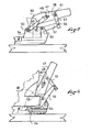
- the figure 1 shows a portion of gliding board 1 on which rests the rear end of a shoe 2.
- the rear end comprises a tip 3 with an upper flange 4.
- the rear end is retained on the gliding board 1 by a retaining member 5 which will now be described.
- This element comprises a base 6 with an upper support plate 7 provided for receiving the shoe sole.
- the base is assembled directly to the ski, or it is slidably mounted in the longitudinal direction defined by the ski. Possibly the base can slide backwards from a defined longitudinal position by compressing a return spring.
- a return spring Such a method of construction is known in the field of ski bindings.
- a ski brake 8 is associated with the base.
- the brake comprises a bearing 9 which is assembled to the base and an actuating pedal connected to the bearing by a return spring and metal wires which extend beyond the bearing to form the braking arms 11 and 12.
- the construction of such a brake is known and will not be described in more detail.
- the brake is optional.
- the base comprises a rising wall 14 which bypasses the rear end of the shoe sole and forming with the support plate 7 a housing for the shoe heel.
- This wall is however optional.
- the element 5 further comprises a retaining body 16 having in its lower part a jaw 17 which holds the boot.
- the jaw has two studs symmetrical with respect to a longitudinal and vertical median plane. Both nipples rest on the rim 4 of the rear shoe tip. The two nipples frame the rear end of the shoe thus ensuring its centering with respect to the restraining element.
- Other solutions may also be appropriate. Especially one could have a continuous jaw shaped crescent.
- the body 16 is mounted in free rotation around a horizontal and transverse axis 18.
- the axis 18 is carried by two arms 20 and 21 whose lower ends are connected to the base 6 by a hinge pin, respectively 22 and 23.
- the shafts 22 and 23 are mounted in the parts of the wall 14 which are oriented parallel to the longitudinal direction defined by the ski.
- the arms can pivot freely about these axes 22 and 23. In the retaining position which is shown in FIG. figure 1 , the arms are oriented in an oblique direction upwards and backwards.
- the assembly formed by the base, the arms, the body and their axes of articulation operates in the manner of a toggle.
- the jaw 17 In the position represented in figure 1 , the jaw 17 is located below the alignment of the axes 22-23, 18, that is to say downward and rearward relative to this alignment.
- the expression "22-23" designates the common axis of the two articulation axes 22 and 23 viewed from the side. As a result, a vertical upward force exerted by the shoe on the jaw tends to bring the arms towards the shoe. Under these conditions, the toggle is in a closed stable position and the retaining element is in the retaining position of the boot.
- the jaw is placed on the tip of the boot, then the upper end of the body is tilted towards the boot upper to close the toggle.
- one of the two axes 22-23 or 18 is mounted with play being elastically biased towards the shoe.
- the shaft 18 is slidably mounted in a lumen 25 of the body.
- the light is oriented in the longitudinal direction of the body and the axis 18 is elastically biased towards the top of the light, that is to say towards the upper end of the body by a spring 26 or a battery of springs placed in parallel.
- the body 16 has a shouldered housing 28 provided for a sliding drawer 27 which is traversed by the axis 18 and for the spring 26.
- One end of the spring bears against one shoulder of the housing and the other end bears against a washer 31 which is traversed by a clamping screw 30 which is screwed into the spool 27. In this way it is possible to adjust the restoring force which is exerted by the spring on the spindle 18 in its slot 25.
- the arms are made of metal and are shaped by folding, their ends being further apart on the side of the base that the side of the body. In this way, by varying the thickness of the material, the desired longitudinal clearance can be obtained by an elastic deformation of the arms.
- the retaining element 5 is provided to cooperate with a complementary element that holds the other end of the shoe.
- This element is of the type with voluntary opening or opening triggered by the level of stresses to which the shoe subjects the binding.
- the body of the retaining element 5 flips on its own to facilitate the release of the boot.
- at least one of the components that are the arms and the body of the rear retention element are biased towards the board 1 by a spring or the like which exerts on the component a reduced intensity return force.
- each of the arms 20 and 21 is biased backwards by a small wire spring 32, 33 one end (not visible) is embedded in the base 6, and the other end 32a, 33a is attached to each of the arms.
- the springs 32 and 33 urge the toggle in the direction of its opening. This occurs effortlessly as soon as the shoe is no longer held by the other end. A minimal displacement of the shoe is sufficient for the springs 32 and 33 bring the knee lever in an unstable position. Once this position is reached, the efforts that the shoe exerts if necessary on the jaw lead to its total tilting so as to release the shoe. Without the presence of the springs there would be a risk that the toggle does not open because the rear end of the shoe biases the jaw in a direction that keeps it in its stable position.
- springs 32 and 33 could be provided with return springs between the arms 20, 21 and the body 16. It could also be placed a resilient return element between the body 16 and the base 6, the important thing being exert on one of the components of the toggle a reduced return force in the unstable position of the toggle.
- the retaining element 5 can be closed by placing the jaw on the rim of the shoe and tilting the body towards the shoe shank as previously mentioned.
- the general idea is to place under the shoe sole an articulated foot pedal which is linked with the body. By pressing the pedal the shoe forces the body to switch to the closed position of the toggle as it engages in the retainer.
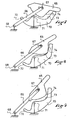
- the element represented in figure 4 comprises as the previous a body 47 connected to a base 46 by two arms, only the arm 48 being visible, with hinge pins 49 and 50.
- the arms 48 and / or the body 47 are biased backwards by a resilient return device of low stiffness, such as for example the spring 51 shown in the figures.
- this or these springs elastically recall the body in the release position of the shoe which is illustrated in FIG. figure 4 . This position is also a waiting position of the shoe.
- a lever 52 is articulated to the base around an axis 53 located on the rear of the base.
- One end 54 of the lever is under the back of the shoe sole when the boot is engaged in the retainer. This end forms the foot pedal on which the shoe is supported. This end is preferably curved upwards.
- the other end 55 of the lever is connected to a link 57 by a hinge 56, and the rod is itself connected to the body 47 about an axis 58 which is located opposite the jaw 60 with respect to the axis 49.
- one of the pins 56 or 58 is mounted with clearance.
- figure 4 it is the connection between the axis 58 and the rod 57 which has play because the axis 58 is mounted in a longitudinal slot 61 of the rod.
- the length of the lever 52, the rod 57 and the position of the axes 53, 56 and 58 makes that in the waiting position of the boot, the foot pedal 54 is raised above the support plate of the shoe.
- the support of the shoe on the pedal 54 causes the lever 52 to tilt as shown in FIG. figure 5 .
- the rod 57 exerts on the body an upward thrust that tilts the body 47 about the axis 49 until the jaw 60 comes into contact with the shoe. This position is illustrated in the figure 5 .
- the rod forces the body to rock, the body acts by reaction on the arms 48 which forces the toggle switch to a stable position of closure.
- This position is illustrated in the figure 6 .
- the light 60 which is in the body and the elastic return of the axis 49 in this light facilitate the passage of the knee to its closed position.
- the light 61 in the rod 57 also facilitates this transition.
- the pedal 54 is preferably retracted into a housing 64 of the base.
- the figure 6 shows the body in this holding position of the shoe.
- lever could act simply by pushing on the body, in particular by cooperation of evolutive ramps between the lever and the body.
- the retaining element comprises a body 65 hinged to arms 66 about an axis 67, the arms themselves being articulated to the base around an axis 68.
- a lever 70 is pivotally mounted about an axis 71 mounted on the base.
- the lever comprises a front pedal 72 and on the rear of the other side of the axis 71 a ramp 73 which is provided to cooperate with a ramp 74 of the body facing the ramp 73.
- the ramps cooperate in an evolutionary manner, that is to say that their respective contact point moves as the lever tilts.
- the contact zone is located towards the end of the lever opposite the pedal 72, this causes the first phase of tilting of the body. Then the contact zone moves in a hollow zone of the ramp 74 cooperating with a ventrue zone of the ramp 73 to cause the tilting of the arms until the closure of the toggle.
- the retainer just described is intended to be used in combination with any other suitable retainer.
- it may be a stirrup-type element with a manual lever for voluntary opening, or a retaining element with trigger whose jaw opens in case of excessive stress exerted by the shoe and remains in this open position a sufficient time to allow the shoe to disengage itself. It can be mounted on a ski, a short ski, a snowboard or generally on any snowboard or rolling.
- the retaining element could be used to retain the front end of the shoe.
Landscapes
- Footwear And Its Accessory, Manufacturing Method And Apparatuses (AREA)
- Lubricants (AREA)
- Braking Arrangements (AREA)
- Closing And Opening Devices For Wings, And Checks For Wings (AREA)
Abstract
Description
L'invention concerne un élément de retenue d'une chaussure sur une planche de glisse ou de roulage.The invention relates to a retaining element of a shoe on a gliding or rolling board.
Plus exactement, l'invention est relative à un élément de retenue non libérable, c'est-à-dire qui n'assure pas lui-même la libération de la chaussure en cas de sollicitation excessive. Pour information, un dispositif de retenue libérable est décrit dans le document
Dans ce document le mécanisme libératoire est logé dans un corps monté pivotant sur un axe porté par deux bras.In this document the release mechanism is housed in a body pivotally mounted on an axis carried by two arms.
L'invention s'applique notamment mais non exclusivement au domaine du ski où il est courant d'attacher une chaussure sur la planche par un élément de retenue avant et un élément de retenue arrière, chacun de ces éléments retenant un embout de la chaussure.The invention applies in particular but not exclusively to the ski area where it is common to attach a shoe on the board by a front retainer and a rear retainer, each of these elements holding a tip of the shoe.
Le dispositif le plus courant pour retenir de façon non libérable l'embout d'une chaussure consiste en un étrier dont les deux extrémités sont ramenées sous la semelle de chaussure Un tel dispositif est par exemple décrit dans la demande de
Ce dispositif à étrier donne de bons résultats, toutefois en cas où cet étrier est basculé pour libérer la chaussure, la chaussure reste engagée dans l'autre étrier et l'utilisateur doit dégager sa chaussure par un mouvement volontaire de dégagement de la chaussure hors de cet étrier.This stirrup device gives good results, however in case this stirrup is tilted to release the shoe, the shoe remains engaged in the other stirrup and the user must release his shoe by a voluntary movement of the shoe release out of this stirrup.
Il existe donc un besoin pour un élément de retenue, de type non libérable qui soit plus pratique d'utilisation et qui libère la chaussure plus facilement en cas d'ouverture de l'autre élément de retenue.There is therefore a need for a non-releasable retaining element which is more convenient to use and which releases the boot more easily in case of opening of the other retaining element.
Les buts de l'invention sont atteints par la fourniture d'un élément de retenue selon la revendication 1.The objects of the invention are achieved by the provision of a retaining element according to claim 1.
A cet effet l'invention propose un élément de retenue qui comprend une embase ayant une plaque d'appui prévue pour recevoir une semelle de chaussure, un corps muni d'une mâchoire de retenue prévue pour retenir un embout de chaussure, le corps étant relié à l'embase par deux bras liaison, et étant relié à ces bras de façon pivotante autour d'un axe supérieur d'articulation transversal, chacun des bras étant relié à l'embase par une articulation autour d'un axe inférieur d'articulation transversal, la mâchoire étant mobile entre une position de retenue où elle est en mesure de retenir l'embout de la chaussure et une position de libération où l'embout de chaussure peut s'échapper, les bras de liaison et le corps formant une genouillère fermée en position de retenue de la mâchoire et ouverte dans la position de libération.For this purpose the invention proposes a retaining element which comprises a base having a support plate provided for receiving a shoe sole, a body provided with a retaining jaw provided for retaining a shoe tip, the body being connected. at the base by two arms link, and being pivotally connected to these arms about an upper axis of transverse articulation, each arm being connected to the base by a hinge about a lower axis of articulation transverse, the jaw being movable between a retaining position where it is able to retain the tip of the shoe and a release position where the shoe tip can escape, the connecting arms and the body forming a toggle joint closed in the jaw retainer position and open in the release position.
L'élément de retenue est caractérisé par le fait qu'au moins en position fermée de la genouillère, un. élément élastique rappelle élastiquement au moins l'un des éléments que sont les bras et le corps vers la position ouverte de la genouillère.The retaining element is characterized in that at least in the closed position of the toggle joint, a. elastic element resiliently recalls at least one of the elements that are the arms and the body to the open position of the toggle.
Ainsi en cas d'ouverture de l'autre élément de retenue de la chaussure, un simple mouvement de déplacement de la chaussure permet à la genouillère de s'ouvrir d'elle-même et de libérer la chaussure.Thus, in case of opening of the other retaining element of the shoe, a simple movement of movement of the shoe allows the toggle to open on its own and release the shoe.
Selon une caractéristique secondaire, la genouillère formée par les bras et le corps est élastiquement extensible pour faciliter la fermeture de la genouillère lors de la mise en place de la chaussure.According to a secondary feature, the knee joint formed by the arms and the body is elastically extensible to facilitate the closure of the knee during the introduction of the shoe.
Selon une autre caractéristique de l'invention, une pédale articulée actionnable par la chaussure commande un levier de basculement du corps dans sa position de retenue.According to another characteristic of the invention, an articulated pedal actuable by the shoe controls a lever for tilting the body in its retaining position.
L'invention sera mieux comprise en se référant à la description qui va suivre et aux dessins qui lui sont attachés.
- La
figure 1 est une vue générale de côté d'un élément de retenue selon un premier mode de mise en oeuvre de l'invention. - La
figure 2 est une vue de dessus de l'élément de lafigure 1 . - La
figure 3 montre en coupe le corps de l'élément de retenue de lafigure 1 . - La
figure 4 est relative à une variante de mise en oeuvre de l'invention. - Les
figures 5 et 6 montrent le dispositif de lafigure 4 dans différentes phases de fonctionnement. - Les
figures 7 à 9 sont relatives à un autre mode de construction.
- The
figure 1 is a general side view of a retaining element according to a first embodiment of the invention. - The
figure 2 is a top view of the element of thefigure 1 . - The
figure 3 shows in section the body of the retaining element of thefigure 1 . - The
figure 4 relates to an alternative embodiment of the invention. - The
Figures 5 and 6 show the device of thefigure 4 in different phases of operation. - The
Figures 7 to 9 relate to another mode of construction.
La
L'extrémité arrière est retenue sur la planche de glisse 1 par un élément de retenue 5 qui va maintenant être décrit.The rear end is retained on the gliding board 1 by a
Cet élément comprend une embase 6 avec une plaque d'appui supérieure 7 prévue pour recevoir la semelle de chaussure.This element comprises a
L'embase est assemblée directement au ski, ou alors elle est montée coulissante selon la direction longitudinale définie par le ski. Eventuellement l'embase peut coulisser vers l'arrière depuis une position longitudinale définie en comprimant un ressort de rappel. Un tel mode de construction est connu dans le domaine des fixations de ski.The base is assembled directly to the ski, or it is slidably mounted in the longitudinal direction defined by the ski. Possibly the base can slide backwards from a defined longitudinal position by compressing a return spring. Such a method of construction is known in the field of ski bindings.
Dans le mode de réalisation représenté, un frein de ski 8 est associé à l'embase. De façon classique le frein comprend un palier 9 qui est assemblé à l'embase et une pédale d'actionnement reliée au palier par un ressort de rappel et des fils métalliques qui se prolongent au-delà du palier pour former les bras de freinage 11 et 12. La construction d'un tel frein est connue et ne sera pas décrite plus en détails. Le frein est par ailleurs facultatif.In the embodiment shown, a ski brake 8 is associated with the base. Conventionally, the brake comprises a bearing 9 which is assembled to the base and an actuating pedal connected to the bearing by a return spring and metal wires which extend beyond the bearing to form the
Dans le mode de réalisation illustré, l'embase comprend une paroi remontante 14 qui contourne l'extrémité arrière de la semelle de chaussure formant ainsi avec la plaque d'appui 7 un logement pour le talon de chaussure. Cette paroi est cependant facultative.In the illustrated embodiment, the base comprises a rising
L'élément 5 comprend par ailleurs un corps de retenue 16 ayant dans sa partie inférieure une mâchoire 17 qui retient la chaussure. Selon le mode de réalisation illustré, la mâchoire a deux tétons symétriques par rapport à un plan longitudinal et vertical médian. Les deux tétons prennent appui sur le rebord 4 de l'embout arrière de chaussure. Les deux tétons encadrent l'extrémité arrière de la chaussure assurant ainsi son centrage par rapport à l'élément de retenue. D'autres solutions pourraient aussi convenir. Notamment on pourrait avoir une mâchoire continue en forme de croissant.The
Le corps 16 est monté en rotation libre autour d'un axe 18 horizontal et transversal. Selon le mode de réalisation illustré l'axe 18 est porté par deux bras 20 et 21 dont les extrémités inférieures sont reliées à l'embase 6 par un axe d'articulation, respectivement 22 et 23. Les axes 22 et 23 sont montés dans les parties de la paroi 14 qui sont orientées parallèlement à la direction longitudinale définie par le ski. Les bras peuvent pivoter librement autour de ces axes 22 et 23. Dans la position de retenue qui est représentée en
L'ensemble formé par l'embase, les bras, le corps et leurs axes d'articulation fonctionne à la façon d'une genouillère. Dans la position représentée en
Lorsque la mâchoire franchit l'alignement des axes, la genouillère passe dans une position instable qui permet à la mâchoire de s'ouvrir pour libérer l'embout de la chaussure.When the jaw crosses the alignment of the axes, the toggle switch goes into an unstable position that allows the jaw to open to release the tip of the shoe.
Pour refermer volontairement l'élément de retenue, la mâchoire est placée sur l'embout de la chaussure, puis l'extrémité supérieure du corps est basculée vers la tige de chaussure pour refermer la genouillère.To deliberately close the retaining element, the jaw is placed on the tip of the boot, then the upper end of the body is tilted towards the boot upper to close the toggle.
Afin de faciliter cette opération de fermeture de la genouillère, de façon optionnelle, l'un des deux axes 22-23 ou 18 est monté avec jeu en étant rappelé élastiquement en direction de la chaussure.To facilitate this operation of closing the toggle, optionally, one of the two axes 22-23 or 18 is mounted with play being elastically biased towards the shoe.
Selon le mode de réalisation illustré, l'axe 18 est monté coulissant dans une lumière 25 du corps. La lumière est orientée selon la direction longitudinale du corps et l'axe 18 est rappelé élastiquement vers le haut de la lumière, c'est-à-dire vers l'extrémité supérieure du corps par un ressort 26 ou une batterie de ressorts placés en parallèle.According to the illustrated embodiment, the
Comme on peut le voir dans la
D'autres modes de construction peuvent aussi convenir. Egalement, au lieu de l'axe 18, on pourrait monter avec jeu l'axe 22-23 dans une lumière. On pourrait également monter l'embase sur une glissière avec un rappel élastique en direction de la chaussure. Une autre possibilité est de donner une élasticité réduite aux bras. Par exemple comme cela est représenté dans la figure, les bras sont réalisés en métal et sont mis en forme par pliage, leurs extrémités étant plus écartées du côté de l'embase que du côté du corps. De cette façon, en jouant sur l'épaisseur de matière on peut obtenir le jeu longitudinal souhaité par une déformation élastique des bras.Other construction methods may also be suitable. Also, instead of the
L'élément de retenue 5 est prévu pour coopérer avec un élément complémentaire qui retient l'autre extrémité de la chaussure. Cet élément est du type à ouverture volontaire ou à ouverture déclenchée par le niveau de sollicitations auxquelles la chaussure soumet la fixation.The retaining
En cas d'ouverture de l'élément de retenue complémentaire, il est prévu que le corps de l'élément de retenue 5 bascule de lui-même pour faciliter la libération de la chaussure. Pour permettre cela, un des constituants au moins que sont les bras et le corps de l'élément de retenue arrière sont rappelés en direction de la planche 1 par un ressort ou autre qui exerce sur le constituant un effort de rappel d'intensité réduite.In case of opening of the complementary retaining element, it is provided that the body of the retaining
Selon le mode de réalisation représenté sur les figures, chacun des bras 20 et 21 est rappelé vers l'arrière par un petit ressort à fil 32, 33 dont une extrémité (non visible) est encastrée dans l'embase 6, et l'autre extrémité 32a, 33a est accrochée à chacun des bras.According to the embodiment shown in the figures, each of the
Les ressorts 32 et 33 sollicitent la genouillère dans le sens de son ouverture. Celle-ci se produit sans effort dès que la chaussure n'est plus retenue par l'autre extrémité. Un déplacement minime de la chaussure est suffisant pour que les ressorts 32 et 33 amènent la genouillère en position instable. Une fois cette position atteinte, les efforts que la chaussure exerce le cas échéant sur la mâchoire conduisent à son basculement total de façon à libérer la chaussure. Sans la présence des ressorts il y aurait un risque que la genouillère ne s'ouvre pas car l'extrémité arrière de la chaussure sollicite la mâchoire dans une direction qui la maintient dans sa position stable.The
En plus des ressorts 32 et 33 on pourrait prévoir des ressorts de rappel entre les bras 20, 21 et le corps 16. On pourrait placer aussi un élément de rappel élastique entre le corps 16 et l'embase 6, l'important étant d'exercer sur un des constituants de la genouillère une force réduite de rappel dans la position instable de la genouillère.In addition to the
Une fois ouverte l'élément de retenue 5 peut être refermé plaçant la mâchoire sur le rebord de la chaussure et en basculant le corps en direction de la tige de la chaussure ainsi que cela a été mentionné précédemment.Once opened, the retaining
Les
L'idée générale est de placer sous la semelle de chaussure une pédale de chaussage articulée qui est liée avec le corps. En prenant appui sur la pédale la chaussure force le corps à basculer en position fermée de la genouillère au fur et à mesure de son engagement dans l'élément de retenue.The general idea is to place under the shoe sole an articulated foot pedal which is linked with the body. By pressing the pedal the shoe forces the body to switch to the closed position of the toggle as it engages in the retainer.
L'élément représenté en
Un levier 52 est articulé à l'embase autour d'un axe 53 situé sur l'arrière de l'embase.A
Une extrémité 54 du levier se trouve sous l'arrière de la semelle de chaussure lorsque la chaussure est engagée dans l'élément de retenue. Cette extrémité forme la pédale de chaussage sur laquelle la chaussure prend appui. Cette extrémité est de préférence recourbée vers le haut.One
L'autre extrémité 55 du levier est reliée à une biellette 57 par une articulation 56, et la biellette est elle-même reliée au corps 47 autour d'un axe 58 qui est situé à l'opposé de la mâchoire 60 par rapport à l'axe 49.The
De préférence un des axes 56 ou 58 est monté avec jeu. Selon la
La longueur du levier 52, de la biellette 57 et la position des axes 53, 56 et 58 fait qu'en position d'attente de la chaussure, la pédale de chaussage 54 est surélevée au-dessus de la plaque d'appui de la chaussure. L'appui de la chaussure sur la pédale 54 provoque le basculement du levier 52 ainsi que cela est représenté dans la
Si la poussée de la chaussure sur la pédale continue, la biellette force le corps à basculer, le corps agit par réaction sur les bras 48 ce qui force la genouillère à passer en position stable de fermeture. Cette position est illustrée dans la
En position fermée de la genouillère, la pédale 54 s'escamote de préférence dans un logement 64 de l'embase. La
D'autres modes de liaison entre le levier et le corps pourraient également convenir.Other modes of connection between the lever and the body could also be suitable.
Par exemple le levier pourrait agir par simple poussée sur le corps, notamment par coopération de rampes évolutives entre le levier et le corps.For example the lever could act simply by pushing on the body, in particular by cooperation of evolutive ramps between the lever and the body.
Les
Comme dans les cas précédents l'élément de retenue comprend un corps 65 articulé à des bras 66 autour d'un axe 67, les bras étant eux-mêmes articulés à l'embase autour d'un axe 68.As in the previous cases, the retaining element comprises a
Un levier 70 est monté basculant autour d'un axe 71 monté sur l'embase. Le levier comprend vers l'avant une pédale 72 et sur l'arrière de l'autre côté de l'axe 71 une rampe 73 qui est prévue pour coopérer avec une rampe 74 du corps en regard de la rampe 73.A
Comme cela est visible sur ces figures, les rampes coopèrent de façon évolutive, c'est-à-dire que leur point de contact respectif se déplace au fur et à mesure du basculement du levier.As can be seen in these figures, the ramps cooperate in an evolutionary manner, that is to say that their respective contact point moves as the lever tilts.
Au début la zone de contact se situe vers l'extrémité du levier opposé à la pédale 72, ceci provoque la première phase de basculement du corps. Puis la zone de contact se déplace dans une zone en creux de la rampe 74 coopérant avec une zone ventrue de la rampe 73 pour provoquer le basculement des bras jusqu'à la fermeture de la genouillère.Initially the contact zone is located towards the end of the lever opposite the
D'autres modes de constructions pourraient aussi convenir.Other modes of construction could also be suitable.
L'élément de retenue qui vient d'être décrit est prévu pour être utilisé en combinaison avec tout autre élément de retenue approprié. Par exemple il peut s'agir d'un élément du type étrier avec un levier manuel d'ouverture volontaire, ou encore d'un élément de retenue avec déclenchement dont la mâchoire s'ouvre en cas de sollicitation excessive exercée par la chaussure et reste dans cette position ouverte un temps suffisant pour permettre à la chaussure de se dégager d'elle-même. Il peut être monté sur un ski, un ski court, un surf de neige ou bien de façon générale sur toute planche de glisse ou de roulage.The retainer just described is intended to be used in combination with any other suitable retainer. For example it may be a stirrup-type element with a manual lever for voluntary opening, or a retaining element with trigger whose jaw opens in case of excessive stress exerted by the shoe and remains in this open position a sufficient time to allow the shoe to disengage itself. It can be mounted on a ski, a short ski, a snowboard or generally on any snowboard or rolling.
Naturellement la présente description n'est donnée qu'à titre indicatif et l'on pourrait adopter d'autres modes de réalisation sans pour autant sortir du cadre de celle-ci.Of course, the present description is given only as an indication and other embodiments could be adopted without departing from the scope thereof.
Notamment l'élément de retenue pourrait être utilisé pour retenir l'extrémité avant de la chaussure.In particular the retaining element could be used to retain the front end of the shoe.
Claims (8)
- Element for retaining a boot on a gliding or rolling board and preventing the release of the boot even in the event of excessive stress, comprising a base (6, 46) having a support plate (14) provided to hold a boot sole, a body (16, 47, 65) provided with a retaining jaw (17, 60) for retaining a boot toecap, the body (16, 47, 65) being connected to the base by two link arms (20, 21, 48, 66) and being connected to these arms such that it can pivot about an upper transverse hinge pin (18, 49, 67), each of the arms being connected to the base by an articulation about a lower transverse hinge pin (22-23, 50, 68), the jaw being able to move between a retaining position in which it is able to retain the boot toecap and a release position in which the boot toecap can be removed, the link arms and the body forming a toggle joint which is closed in the retaining position of the jaw and open in the release position, characterized in that, at least when the toggle joint is in the closed position, an elastic element (32, 33, 51) elastically returns at least one of the components out of the arms (20, 21, 48, 66) and the body (16, 47, 65) to the open position of the toggle joint, in that it comprises an articulated fitting pedal (54, 72) which engages with the body (47, 65) so as to tip the body into the closed position of the toggle joint, and in that the fitting pedal (54, 72) is the end of a lever (52, 70) hinged about a transverse pin (53, 71) on the base (46) and that the part of the lever opposite the pedal with respect to its pin is connected to the body by a link.
- Element according to Claim 1, characterized in that it comprises an elastic return means between the body (16) and the base (6).
- Element according to Claim 1, characterized in that each of the arms (20, 21) is returned towards the rear by a small wire spring (32, 33) one end of which is fitted in the base (6) and the other end (32a, 33a) is hooked on one each of the arms.
- Element according to Claim 1, characterized in that it comprises an elastic return means between the arms (20, 21) and the body (16).
- Element according to Claim 1, characterized in that the pin (18) hinging the body (16) to the arms (20, 21) is secured in a hole (25) in the body aligned in the longitudinal direction of the body and in that a return spring (26) pushes the pin (18) elastically towards one end of the hole.
- Element according to Claim 3, characterized in that the body (16) has a shouldered housing (28) intended for a slide (27) through which the pin (18) passes and for the spring (26), and in that one end of the spring presses against a shoulder of the housing and the other end presses against a clamping screw (30) screwed into the slide (27).
- Element according to Claim 1, characterized in that the lever (52) engages with the body (47) via a link rod (57) hinged on one side to the lever (52) and on the other to the body (47).
- Element according to Claim 1, characterized in that the lever (70) engages with the body (65) via two progressive ramps (73, 74) of the body and of the lever.
Applications Claiming Priority (2)
| Application Number | Priority Date | Filing Date | Title |
|---|---|---|---|
| FR0311900 | 2003-10-10 | ||
| FR0311900A FR2860729B1 (en) | 2003-10-10 | 2003-10-10 | RETAINING ELEMENT OF A SHOE ON A SLIDING OR ROLLING BOARD |
Publications (2)
| Publication Number | Publication Date |
|---|---|
| EP1522334A1 EP1522334A1 (en) | 2005-04-13 |
| EP1522334B1 true EP1522334B1 (en) | 2010-09-15 |
Family
ID=34307529
Family Applications (1)
| Application Number | Title | Priority Date | Filing Date |
|---|---|---|---|
| EP04023878A Not-in-force EP1522334B1 (en) | 2003-10-10 | 2004-10-07 | Shoe binding for a sports board |
Country Status (4)
| Country | Link |
|---|---|
| EP (1) | EP1522334B1 (en) |
| AT (1) | ATE481142T1 (en) |
| DE (1) | DE602004029126D1 (en) |
| FR (1) | FR2860729B1 (en) |
Families Citing this family (4)
| Publication number | Priority date | Publication date | Assignee | Title |
|---|---|---|---|---|
| SE9803384L (en) | 1998-03-02 | 1999-09-03 | Kemira Kemi Ab | Process for treating process water |
| FR2909761B1 (en) | 2006-12-11 | 2009-03-13 | Salomon Sa | METHOD FOR CONTROLLING THE CONNECTION BETWEEN AN INDIVIDUAL AND ITS SLIDING OR ROLLING MACHINE AND DEVICE FOR CARRYING OUT THE METHOD |
| FR2936428B1 (en) * | 2008-09-29 | 2010-10-01 | Rossignol Sa | FIXING TALONNIERE FOR MOBILE BODY SKI SHOE |
| AT513694B1 (en) * | 2012-12-07 | 2015-11-15 | Gattinger Erwin | Ski binding for short skis |
Family Cites Families (7)
| Publication number | Priority date | Publication date | Assignee | Title |
|---|---|---|---|---|
| DE1428883A1 (en) * | 1964-07-08 | 1969-02-06 | Ess Skibeschlag | Heel safety ski binding |
| FR2157686B1 (en) * | 1971-10-19 | 1976-06-04 | Salomon Georges P J | |
| FR2258876B1 (en) * | 1974-01-28 | 1978-02-10 | Salomon & Fils F | |
| FR2269982A1 (en) * | 1974-02-07 | 1975-12-05 | Salomon & Fils F | Ski boot binding method with pivotal clamp - has rockers maintaining fixed angular clamp position during start of clamping |
| FR2368973A1 (en) * | 1976-10-28 | 1978-05-26 | Beyl Jean Joseph Alfred | HEEL FOR SECURING A BOOT ON A SKI OR ON A BINDING PLATE |
| US4168084A (en) * | 1978-01-30 | 1979-09-18 | Kurt von Besser | Ski binding having a step-in clamping device |
| FR2803215B3 (en) | 1999-12-30 | 2002-03-01 | Salomon Sa | SHOE RETAINING ASSEMBLY ON A SNOWBOARD |
-
2003
- 2003-10-10 FR FR0311900A patent/FR2860729B1/en not_active Expired - Fee Related
-
2004
- 2004-10-07 DE DE602004029126T patent/DE602004029126D1/en active Active
- 2004-10-07 EP EP04023878A patent/EP1522334B1/en not_active Not-in-force
- 2004-10-07 AT AT04023878T patent/ATE481142T1/en not_active IP Right Cessation
Also Published As
| Publication number | Publication date |
|---|---|
| FR2860729B1 (en) | 2006-04-28 |
| FR2860729A1 (en) | 2005-04-15 |
| EP1522334A1 (en) | 2005-04-13 |
| DE602004029126D1 (en) | 2010-10-28 |
| ATE481142T1 (en) | 2010-10-15 |
Similar Documents
| Publication | Publication Date | Title |
|---|---|---|
| EP0679415B1 (en) | Binding for a skiing device | |
| EP1611929B1 (en) | Facilitating fitting and removal device for a snowboard binding | |
| EP0850670B1 (en) | In-line skate with removable shoe | |
| FR2738157A1 (en) | AUTOMATIC FIXING DEVICE | |
| EP3416732B1 (en) | Element for maintaining a ski shoe with a step-in pedal that can tilt relative to the heel hold down | |
| EP2769755B1 (en) | Front unit with automatic triggering when twisted | |
| FR2642980A1 (en) | Binding device for a cross-country ski and boot intended for such a binding device | |
| WO1996032992A1 (en) | Safety binding for telemark, cross-country and ski-jumping skis | |
| EP3437703B1 (en) | Braking device for mountaineering ski | |
| FR2741543A1 (en) | Binding for cross country ski boot with axle | |
| EP2552559A1 (en) | Binding for the practice of skiing | |
| EP0634197B1 (en) | Alpine ski binding | |
| EP1522334B1 (en) | Shoe binding for a sports board | |
| EP0634196A1 (en) | Binding element for alpine skis | |
| EP1785172B1 (en) | Sportshoe binding system on to a glide board | |
| FR2632871A1 (en) | SKI SHOE WITH AUTOMATIC CLOSURE | |
| WO2004016330A2 (en) | Fixing device with integrated catching means | |
| FR2742061A1 (en) | DEVICE FOR RETAINING A SHOE TO A SNOWBOARD SUCH AS A SKI OR THE LIKE | |
| EP3741436A1 (en) | Binding device for fixing a boot onto a snowboard | |
| FR2758468A1 (en) | Fixing of sports boot on ski | |
| FR2738156A1 (en) | AUTOMATIC FIXING AND UNLOCKING DEVICE | |
| FR2843310A1 (en) | FRONT LOADING FIXING DEVICE | |
| FR2758469A1 (en) | Fixing of boot on sports board | |
| EP0495737B1 (en) | Skibrake | |
| EP1319424A1 (en) | Fixation device of a boot to a sports article without lifting |
Legal Events
| Date | Code | Title | Description |
|---|---|---|---|
| PUAI | Public reference made under article 153(3) epc to a published international application that has entered the european phase |
Free format text: ORIGINAL CODE: 0009012 |
|
| AK | Designated contracting states |
Kind code of ref document: A1 Designated state(s): AT BE BG CH CY CZ DE DK EE ES FI FR GB GR HU IE IT LI LU MC NL PL PT RO SE SI SK TR |
|
| AX | Request for extension of the european patent |
Extension state: AL HR LT LV MK |
|
| 17P | Request for examination filed |
Effective date: 20051013 |
|
| AKX | Designation fees paid |
Designated state(s): AT CH DE IT LI |
|
| 17Q | First examination report despatched |
Effective date: 20061228 |
|
| RAP1 | Party data changed (applicant data changed or rights of an application transferred) |
Owner name: SALOMON S.A.S. |
|
| GRAP | Despatch of communication of intention to grant a patent |
Free format text: ORIGINAL CODE: EPIDOSNIGR1 |
|
| GRAS | Grant fee paid |
Free format text: ORIGINAL CODE: EPIDOSNIGR3 |
|
| GRAA | (expected) grant |
Free format text: ORIGINAL CODE: 0009210 |
|
| AK | Designated contracting states |
Kind code of ref document: B1 Designated state(s): AT CH DE IT LI |
|
| REG | Reference to a national code |
Ref country code: CH Ref legal event code: EP |
|
| REF | Corresponds to: |
Ref document number: 602004029126 Country of ref document: DE Date of ref document: 20101028 Kind code of ref document: P |
|
| PG25 | Lapsed in a contracting state [announced via postgrant information from national office to epo] |
Ref country code: AT Free format text: LAPSE BECAUSE OF FAILURE TO SUBMIT A TRANSLATION OF THE DESCRIPTION OR TO PAY THE FEE WITHIN THE PRESCRIBED TIME-LIMIT Effective date: 20100915 |
|
| PGFP | Annual fee paid to national office [announced via postgrant information from national office to epo] |
Ref country code: DE Payment date: 20101215 Year of fee payment: 7 |
|
| PG25 | Lapsed in a contracting state [announced via postgrant information from national office to epo] |
Ref country code: IT Free format text: LAPSE BECAUSE OF FAILURE TO SUBMIT A TRANSLATION OF THE DESCRIPTION OR TO PAY THE FEE WITHIN THE PRESCRIBED TIME-LIMIT Effective date: 20100915 |
|
| REG | Reference to a national code |
Ref country code: CH Ref legal event code: PL |
|
| PLBE | No opposition filed within time limit |
Free format text: ORIGINAL CODE: 0009261 |
|
| STAA | Information on the status of an ep patent application or granted ep patent |
Free format text: STATUS: NO OPPOSITION FILED WITHIN TIME LIMIT |
|
| PG25 | Lapsed in a contracting state [announced via postgrant information from national office to epo] |
Ref country code: LI Free format text: LAPSE BECAUSE OF NON-PAYMENT OF DUE FEES Effective date: 20101031 Ref country code: CH Free format text: LAPSE BECAUSE OF NON-PAYMENT OF DUE FEES Effective date: 20101031 |
|
| 26N | No opposition filed |
Effective date: 20110616 |
|
| REG | Reference to a national code |
Ref country code: DE Ref legal event code: R097 Ref document number: 602004029126 Country of ref document: DE Effective date: 20110616 |
|
| PG25 | Lapsed in a contracting state [announced via postgrant information from national office to epo] |
Ref country code: DE Free format text: LAPSE BECAUSE OF NON-PAYMENT OF DUE FEES Effective date: 20130501 |
|
| REG | Reference to a national code |
Ref country code: DE Ref legal event code: R119 Ref document number: 602004029126 Country of ref document: DE Effective date: 20130501 |