EP2155535B1 - Verfahren zur konstruktion der lasttragenden struktur einer fahrzeugkarosserie und auf diese weise konstruierte lasttragende struktur - Google Patents
Verfahren zur konstruktion der lasttragenden struktur einer fahrzeugkarosserie und auf diese weise konstruierte lasttragende struktur Download PDFInfo
- Publication number
- EP2155535B1 EP2155535B1 EP08763227A EP08763227A EP2155535B1 EP 2155535 B1 EP2155535 B1 EP 2155535B1 EP 08763227 A EP08763227 A EP 08763227A EP 08763227 A EP08763227 A EP 08763227A EP 2155535 B1 EP2155535 B1 EP 2155535B1
- Authority
- EP
- European Patent Office
- Prior art keywords
- type
- wall
- members
- extruded
- frame
- Prior art date
- Legal status (The legal status is an assumption and is not a legal conclusion. Google has not performed a legal analysis and makes no representation as to the accuracy of the status listed.)
- Not-in-force
Links
- 238000000034 method Methods 0.000 title claims description 12
- 238000005304 joining Methods 0.000 claims abstract description 15
- 229910001092 metal group alloy Inorganic materials 0.000 claims description 7
- 238000010276 construction Methods 0.000 claims description 5
- 230000013011 mating Effects 0.000 claims description 3
- 229920003023 plastic Polymers 0.000 claims description 2
- 239000004033 plastic Substances 0.000 claims description 2
- 239000000463 material Substances 0.000 claims 1
- 239000007769 metal material Substances 0.000 claims 1
- 210000003414 extremity Anatomy 0.000 description 11
- 238000003466 welding Methods 0.000 description 5
- 238000001125 extrusion Methods 0.000 description 4
- 238000004026 adhesive bonding Methods 0.000 description 3
- 210000001503 joint Anatomy 0.000 description 3
- 239000011521 glass Substances 0.000 description 2
- 238000004519 manufacturing process Methods 0.000 description 2
- 229910000831 Steel Inorganic materials 0.000 description 1
- 238000005520 cutting process Methods 0.000 description 1
- 238000003780 insertion Methods 0.000 description 1
- 230000037431 insertion Effects 0.000 description 1
- 238000003825 pressing Methods 0.000 description 1
- 239000010959 steel Substances 0.000 description 1
- 210000001364 upper extremity Anatomy 0.000 description 1
Images



Classifications
-
- B—PERFORMING OPERATIONS; TRANSPORTING
- B62—LAND VEHICLES FOR TRAVELLING OTHERWISE THAN ON RAILS
- B62D—MOTOR VEHICLES; TRAILERS
- B62D23/00—Combined superstructure and frame, i.e. monocoque constructions
-
- B—PERFORMING OPERATIONS; TRANSPORTING
- B62—LAND VEHICLES FOR TRAVELLING OTHERWISE THAN ON RAILS
- B62D—MOTOR VEHICLES; TRAILERS
- B62D23/00—Combined superstructure and frame, i.e. monocoque constructions
- B62D23/005—Combined superstructure and frame, i.e. monocoque constructions with integrated chassis in the whole shell, e.g. meshwork, tubes, or the like
-
- B—PERFORMING OPERATIONS; TRANSPORTING
- B62—LAND VEHICLES FOR TRAVELLING OTHERWISE THAN ON RAILS
- B62D—MOTOR VEHICLES; TRAILERS
- B62D27/00—Connections between superstructure or understructure sub-units
-
- B—PERFORMING OPERATIONS; TRANSPORTING
- B62—LAND VEHICLES FOR TRAVELLING OTHERWISE THAN ON RAILS
- B62D—MOTOR VEHICLES; TRAILERS
- B62D27/00—Connections between superstructure or understructure sub-units
- B62D27/02—Connections between superstructure or understructure sub-units rigid
-
- B—PERFORMING OPERATIONS; TRANSPORTING
- B62—LAND VEHICLES FOR TRAVELLING OTHERWISE THAN ON RAILS
- B62D—MOTOR VEHICLES; TRAILERS
- B62D27/00—Connections between superstructure or understructure sub-units
- B62D27/02—Connections between superstructure or understructure sub-units rigid
- B62D27/023—Assembly of structural joints
-
- B—PERFORMING OPERATIONS; TRANSPORTING
- B62—LAND VEHICLES FOR TRAVELLING OTHERWISE THAN ON RAILS
- B62D—MOTOR VEHICLES; TRAILERS
- B62D29/00—Superstructures, understructures, or sub-units thereof, characterised by the material thereof
- B62D29/008—Superstructures, understructures, or sub-units thereof, characterised by the material thereof predominantly of light alloys, e.g. extruded
-
- Y—GENERAL TAGGING OF NEW TECHNOLOGICAL DEVELOPMENTS; GENERAL TAGGING OF CROSS-SECTIONAL TECHNOLOGIES SPANNING OVER SEVERAL SECTIONS OF THE IPC; TECHNICAL SUBJECTS COVERED BY FORMER USPC CROSS-REFERENCE ART COLLECTIONS [XRACs] AND DIGESTS
- Y10—TECHNICAL SUBJECTS COVERED BY FORMER USPC
- Y10T—TECHNICAL SUBJECTS COVERED BY FORMER US CLASSIFICATION
- Y10T29/00—Metal working
- Y10T29/49—Method of mechanical manufacture
- Y10T29/49616—Structural member making
- Y10T29/49622—Vehicular structural member making
Definitions
- This invention relates to a process for constructing the loadbearing structure of a motor vehicle body, and loadbearing structure so constructed.
- the invention relates to a process for producing a loadbearing structure, comprising the assembly of a frame including a plurality of extruded profiled members of, for example, light metal alloy, of essentially box cross-section, connected together directly or through joining members.
- One object of this invention is to provide a loadbearing structure for a motor vehicle body, and a process for constructing it, which make it possible to overcome the abovementioned disadvantages of the arrangements according to the known art.
- reference 1 indicates as a whole a loadbearing structure of a motor vehicle body constructed according to this invention.
- Loadbearing structure 1 comprises a frame 2, shown alone in Figure 2 , constructed of extruded profiled members, preferably of light metal alloy, of essentially box cross-section.
- frame 2 is assembled using only a first and a second type of extruded profiles, indicated in general by the letters A and B respectively (see in particular Figures 3 and 4 ).
- an extruded profile of the first type has an upper wall 3, an outer side wall 4, an inner side wall 5 and a bottom wall 6. In the example illustrated it is curved and externally convex.
- Upper wall 3 of a profile of type A forms a lateral fin 3a projecting beyond outer lateral wall 4, which in turn forms a lower fin 4a which projects downwards beyond bottom wall 6.
- reference 5a indicates an inner lateral fin of a type A profile, the fin extending from the joint between inner wall 5 and bottom wall 6 in a plane which is essentially below that of upper wall 3. Fin 5a may also extend from the intermediate part of side wall 5, or bottom wall 6.
- an extruded profile of the second type, or type B has an essentially rectangular cross-section, with two larger walls 7 and 8, and two smaller walls 9 and 10. Larger wall 8 extends laterally forming two longitudinal fins 8a and 8b projecting on opposite sides.
- profiles of the first type or type A are meant profiles having the general shape described above with reference to Figure 3 , which are or can be produced using the same extrusion equipment, but which may differ from each other in some geometrical parameter which can be modified in the course of extrusion, such as the curvature of the profile and the dimensions (width, thickness) of the various parts of the profile, such as the fins described above. Similar considerations apply to profiles of the second type or type B.
- frame 2 of the body illustrated by way of example comprises a plurality of extruded profiles of the first type or type A, which will now be described.
- Lateral uprights 11 of windscreen opening 12, and the longitudinal lateral members 13 of the roof of the motor vehicle are constructed using extruded profiles of type A.
- Lower cross-member 14 and upper cross-member 15 of windscreen opening 12, and intermediate cross-members 16, 17 and rear cross-member 18 of the roof are profiles of the second type.
- connection between lateral uprights 11 and upper cross-member 15 of windscreen opening 12, and the forward extremities of longitudinal members 13 of the roof are constructed using two joining members 19, which are symmetrical mirror images of each other.
- FIG. 5 One of these connections is illustrated in Figure 5 , in which the shape of a joining member 19 can be more clearly seen.
- This joining member has two limbs 19a and 19b, in longitudinal alignment with each other, of cross-section corresponding to the transverse shape of profiles 11 and 13 connected thereto.
- limbs 19a and 19b have corresponding projections 19c and 19d which can be inserted into the corresponding longitudinal cavities of associated profiles 11 and 13 forming a mating connection.
- the connection can be stabilised, for example by welding or adhesive bonding, or by other known techniques.
- Joining member 19 has a transverse limb 19e whose cross-section has essentially the same transverse shape as profile 15, of type B, to which it is functionally connected.
- This limb 19e of junction member 19 has a projection 19f which can be inserted into the corresponding axial cavity of cross-member 15 in a mating manner.
- the connection between limb 19e and cross-member 15 can also be stabilised by for example welding, adhesive bonding or other techniques in themselves known.
- frame 2 constructed using profiles of type B form the lateral uprights 20 or 21 of rear side windows 22, and the lower cross-member 23 of this opening.
- Rear cross-member 18 of the roof, the rear extremities of longitudinal members 13 thereof and the upper extremities of uprights 21 are connected together by means of a further pair of joining members 24.
- These joining members are similar to members 19 already described, and differ from them in the fact that they have two limbs having a transverse shape of that of type B profiles, and a single limb having a transverse shape corresponding to that of type A profiles.
- Joining members 24 are also conveniently connected to profiles 13, 18 and 21 by means of male/female type insertions, preferably stabilised by for example welding, adhesive bonding or other techniques in themselves known.
- Figure 6 shows a direct connection between a profile of type A (longitudinal member 13 of the roof) and a profile of type B (cross-member 16 of the roof).
- the connection is made after part of fin 5a of the type A profile (13) has been cut and /or fins 8a and 8b of the type B profile (16) have been partly cut in such a way that the box portion of the type B profile (16) can be abutted against the inner wall 5 of the type A profile (13).
- fin 5a and/or fins 8a and 8b can be inserted, and these are within the scope of those skilled in the art.
- the butt joint between the type A profile and a type B profile can then be stabilised by for example welding, as illustrated in Figure 6 , in which this weld is indicated by 25.
- curved members 26 and 27 corresponding to the fore and rear wheel arches respectively are also constructed using type B profiles.
- the transverse cross-section of these members is substantially the same general cross-section of type B profiles.
- the curvature of these members 26 and 27 is brought about in a manner which is itself known in the course of extrusion, or subsequently, by cold or hot working.
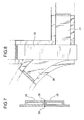
- Curved profiled members 26 in the embodiment illustrated by way of example are tangential to front longitudinal members 28 adjacent to them, which extend essentially horizontally. Conveniently, in the area in which they touch, the box parts of these profiles 26 and 28 are brought into contact and then stabilised, for example by means of welding, after portions of their adjacent fins have been correspondingly cut off, as shown in Figure 7 . The weld between these profiles is indicated by 29.
- Figure 8 shows the connection between the rear extremity of a curved profile 26, an adjacent vertical upright 3, and a lower longitudinal member 31 of frame 2 in an almost frontal perspective view. This joint is also made after parts of the fins of the three profiles used, all of which belong to the type previously defined as type B, have been previously cut.
- Figure 9 shows one example of how connection between type B profiles can be made, in particular at the points indicated by IX in Figure 2 , in the frontal part of frame 2 of the body.
- connection between the forward extremities of longitudinal members 28, a forward cross-member 32 and two small essentially vertical uprights 33 is shown.
- Other forms of connection are however possible.
- Loadbearing structure 1 is obtained by connecting a plurality of elements, such as panels and shells, made by the cutting, pressing and drawing of sheet members, in particular light metal alloy sheets, to frame 2.
- curved profiles 26 and 27 are associated with corresponding wheel arch shells indicated by 34 and 35 in Figure 1 .
- a shaped panel 35 which can also act as a flame-stop wall, is attached to lower cross-member 14 of windscreen opening 12.
- a floor or platform 36 connected to rear wheel arch shell 35 and a rear cross-member 37 of the frame (a cross-member which is also incidentally made using an extruded profile of type B) is located between longitudinal members 31 beneath the doors.
- a tunnel-shaped member 38 may be incorporated into or attached to floor or platform 36.
- Loadbearing structure 1 may be supplemented with a pair of central columns or uprights 40, made for example using a pressed sheet of light metal alloy.
- fins 3a of profiles 11 and 13 of type A are used for attachment of the roof panels.
- Lower fin 4a of uprights 11 and longitudinal members 13, and the fin of upright 20 facing the front of the frame are used to attach the seals which provide a seal for the doors.
- Lower fin 4a of longitudinal members 13 and the fins of profiles 20, 21 and 23 facing into opening 22 for the rear windows are used to form the supporting surface for the glass of these windows.
- Inner fins 5a of uprights 11 and the fins mutually facing cross-members 14 and 15 are used as a whole to form a supporting surface for the windscreen glass.
- walls 5 of type A profiles and side walls 9 of type B profiles are conveniently and preferably of the same external height.
- extruded profiled members of light metal alloy is the currently preferred option
- the invention can be similarly implemented using extruded profiled steel members, or plastics sections, which may be reinforced.
- cross-member 32 can be connected to profiled members 28 and 33 in a way in which it can be dismantled, so as to allow easier access to and possible removal of any mechanical units in the vehicle's forward space or bonnet.
- the invention is not restricted to the construction of loadbearing structures for motor vehicle bodies of the station wagon type, as illustrated in Figure 2 , but is suitable for the construction of loadbearing structures of a great variety of shapes, such as bodies of the saloon, coupé, pick-up, etc., type.
Landscapes
- Engineering & Computer Science (AREA)
- Chemical & Material Sciences (AREA)
- Combustion & Propulsion (AREA)
- Transportation (AREA)
- Mechanical Engineering (AREA)
- Architecture (AREA)
- Structural Engineering (AREA)
- Body Structure For Vehicles (AREA)
- Arrangement Or Mounting Of Propulsion Units For Vehicles (AREA)
Claims (10)
- Lasttragende Struktur (1) für eine Kraftfahrzeugkarosserie, die einen Rahmen (2), der eine Vielzahl extrudierter Profilelemente (11-33, 37) mit im Wesentlichen kastenförmigem Querschnitt enthält, die direkt oder über verbindende Elemente (19, 24) miteinander verbunden sind,
dadurch gekennzeichnet, dass der Rahmen (2) nur umfasst:einen ersten Typ (A) extrudierter Profile, die eine obere Wand (3), eine äußere Seitenwand (4), eine innere Seitenwand (5) und eine untere Wand (6) aufweisen, wobei die obere Wand (3) eine seitliche Rippe (3a) aufweist, die über die äußere Seitenwand (4) hinaus vorsteht, die ihrerseits eine untere Rippe (4a) aufweist, die über die untere Wand (6) hinaus nach unten vorsteht, wobei sich eine innere seitliche Rippe (5a) von der inneren Wand (5) und/oder der unteren Wand (6) in einer Ebene erstreckt, die im Wesentlichen unterhalb der der oberen Wand (3) liegt, undeine zweite Gruppe (B) extrudierter Profile mit im Wesentlichen rechteckigen Querschnitt, wobei sich eine ihrer Wände (8) so erstreckt, dass sie zwei Längsrippen (8a, 8b) aufweist, die an einander gegenüberliegenden Seiten vorstehen,wobei der erste Typ (A) extrudierter Profile verwendet wird, um die seitlichen Stützen (11) der Windschutzscheibenöffnung (12) und die in Längsrichtung verlaufenden seitlichen Elemente (13) des Kraftfahrzeugdachs zu bilden, undder zweite Typ (B) extrudierter Profile eingesetzt wird, um den Rest des Rahmens (2) auszubilden. - Lasttragende Struktur nach Anspruch 1, wobei in dem Rahmen (2) zwei Profile eines Typs (A; B) mit einem Profil des anderen Typs (B; A) über ein verbindendes Element (19, 24) verbunden sind, das zwei Schenkel (19a, 19b) mit einem Querschnitt, der im Wesentlichen identisch mit dem der zwei Profile ist, sowie einen dritten Schenkel (19e) aufweist, der einen Querschnitt hat, der im Wesentlichen identisch mit dem des Profils des anderen Typs (B; A) ist.
- Lasttragende Struktur nach Anspruch 2, wobei die Schenkel des verbindenden Elementes (19; 24) mit entsprechenden äußeren Enden der Profilelemente (A; B) durch Eingriffsverbindungen, insbesondere vom Vorsprung-Loch-Typ, verbunden sind, die durch feste Verbindungseinrichtungen stabilisiert werden.
- Lasttragende Struktur nach einem der vorangehenden Ansprüche, wobei zwei oder mehr Profilelemente des zweiten Typs (B) miteinander verbunden werden, indem ihre entsprechenden Kastenabschnitte nach vorheriger teilweiser Entfernung wenigstens einer Rippe von wenigstens einem von ihnen zusammengesetzt werden.
- Lasttragende Struktur nach einem der vorangehenden Ansprüche, wobei die Höhe der inneren Wand (5) eines Profils des ersten Typs (A) im Wesentlichen die gleiche ist wie die Höhe einer entsprechenden Seitenwand (9) eines Profils des anderen Typs (B).
- Lasttragende Struktur nach einem der vorangehenden Ansprüche, wobei die geformten Elemente, wie beispielsweise wenigstens eine Bodenplatte oder Plattform (36) und vordere (34) sowie hintere (35) Radlaufschalen, an dem Rahmen (2) angebracht sind.
- Lasttragende Struktur nach einem der vorangehenden Ansprüche, wobei die extrudierten Profilelemente aus Metalllegierung, insbesondere einer Leichtmetalllegierung, bestehen.
- Lasttragende Struktur nach einem der Ansprüche 1 bis 6, wobei die extrudierten Profilelemente aus einem Kunststoffmaterial bestehen.
- Lasttragende Struktur nach einem der vorangehenden Ansprüche, wobei die verbindenden Elemente (19, 24) aus gepresstem Metallmaterial bestehen.
- Verfahren zur Herstellung einer lasttragende Struktur (1) einer Kraftfahrzeugkarosserie, das die Montage eines Rahmens (2) einschließt, der eine Vielzahl extrudierter Profilelemente (11-33; 37) mit im Wesentlichen kastenförmigem Querschnitt enthält, die direkt oder über verbindende Elemente (19, 24) miteinander verbunden sind, wobei der Prozess dadurch gekennzeichnet ist, dass der Rahmen (2) unter Verwendung lediglich der folgenden Elemente zusammengesetzt wird:eines ersten Typs (A) extrudierter Profile, die eine obere Wand (3), eine äußere Seitenwand (4), eine innere Seitenwand (5) und eine untere Wand (6) aufweisen, wobei die obere Wand (3) eine seitliche Rippe (3a) aufweist, die über die äußere Seitenwand (4) hinaus vorsteht, die ihrerseits eine untere Rippe (4a) aufweist, die über die untere Wand (6) hinaus nach unten vorsteht, wobei sich eine innere seitliche Rippe (5a) von der inneren Wand (5) und/oder der unteren Wand (6) in einer Ebene erstreckt, die im Wesentlichen unterhalb der der oberen Wand (3) liegt, undeiner zweiten Gruppe (B) extrudierter Profile mit im Wesentlichen rechteckigem Querschnitt, wobei sich eine ihrer Wände (8) so erstreckt, dass sie zwei Längsrippen (8a, 8b) aufweist, die an einander gegenüberliegenden Seiten vorstehen,wobei der erste Typ (A) extrudierter Profile verwendet wird, um die seitlichen Stützen (11) der Windschutzscheibenöffnung (12) und die in Längsrichtung verlaufenden seitlichen Elemente (13) des Kraftfahrzeugdachs zu bilden, undder zweite Typ (B) extrudierter Profile eingesetzt wird, um den Rest des Rahmens (2) auszubilden.
Applications Claiming Priority (2)
| Application Number | Priority Date | Filing Date | Title |
|---|---|---|---|
| IT000404A ITTO20070404A1 (it) | 2007-06-08 | 2007-06-08 | Procedimento per la realizzazione della struttura portante della carrozzeria di un autoveicolo, e struttura portante cosi realizzata. |
| PCT/IB2008/052230 WO2008149317A2 (en) | 2007-06-08 | 2008-06-06 | Process for constructing the loadbearing structure of a motor vehicle body, and loadbearing structure so constructed |
Publications (2)
| Publication Number | Publication Date |
|---|---|
| EP2155535A2 EP2155535A2 (de) | 2010-02-24 |
| EP2155535B1 true EP2155535B1 (de) | 2011-03-16 |
Family
ID=39926702
Family Applications (1)
| Application Number | Title | Priority Date | Filing Date |
|---|---|---|---|
| EP08763227A Not-in-force EP2155535B1 (de) | 2007-06-08 | 2008-06-06 | Verfahren zur konstruktion der lasttragenden struktur einer fahrzeugkarosserie und auf diese weise konstruierte lasttragende struktur |
Country Status (14)
| Country | Link |
|---|---|
| US (1) | US20100181804A1 (de) |
| EP (1) | EP2155535B1 (de) |
| JP (1) | JP2010528926A (de) |
| KR (1) | KR20100019490A (de) |
| CN (1) | CN101720292B (de) |
| AT (1) | ATE501919T1 (de) |
| BR (1) | BRPI0813343A2 (de) |
| CA (1) | CA2688281A1 (de) |
| DE (1) | DE602008005580D1 (de) |
| ES (1) | ES2362339T3 (de) |
| IT (1) | ITTO20070404A1 (de) |
| MX (1) | MX2009013128A (de) |
| RU (1) | RU2428343C1 (de) |
| WO (1) | WO2008149317A2 (de) |
Families Citing this family (16)
| Publication number | Priority date | Publication date | Assignee | Title |
|---|---|---|---|---|
| DE102010054935B4 (de) * | 2010-12-17 | 2013-11-28 | Daimler Ag | Karosseriemodulbauteil |
| KR101239623B1 (ko) * | 2011-04-18 | 2013-03-07 | (주)에이치케이 | 복합재료의 프레임 및 그의 조립방법 |
| CN103359174A (zh) * | 2012-03-31 | 2013-10-23 | 湖南晟通科技集团有限公司 | 一种铝合金全承载式车身 |
| US8657368B2 (en) * | 2012-07-12 | 2014-02-25 | Ford Global Technologies, Llc | Hydroformed side pillar to lower back joint structure |
| USD704098S1 (en) * | 2012-12-20 | 2014-05-06 | Ford Motor Company | Vehicle exterior |
| US8887398B1 (en) | 2013-04-29 | 2014-11-18 | Tesla Motors, Inc. | Extruded member with altered radial fins |
| DE202015101053U1 (de) * | 2014-03-17 | 2015-05-12 | Ford Global Technologies, Llc | Formation in hohlem extrudiertem Fahrzeugrahmenbauteil zur Befestigung einer Baugruppe und Formungsverfahren dafür |
| JP6109271B2 (ja) * | 2015-02-06 | 2017-04-05 | 株式会社神戸製鋼所 | 接合構造体、及び接合構造体の製造方法 |
| MX386314B (es) * | 2015-04-30 | 2025-03-18 | Baomarc Automotive Solutions S P A | Chasis de un autobus o un vehiculo de transporte industrial. |
| JP6489088B2 (ja) * | 2016-08-26 | 2019-03-27 | トヨタ自動車株式会社 | 車両用骨格構造 |
| US9988093B2 (en) * | 2016-09-28 | 2018-06-05 | Ford Global Technologies, Llc | Exoskeleton vehicle upper body structure |
| DE202017105474U1 (de) * | 2017-09-08 | 2018-12-14 | Edag Engineering Gmbh | Materialoptimierter Verbindungsknoten |
| KR102807543B1 (ko) * | 2019-12-17 | 2025-05-13 | 현대자동차주식회사 | 차체 조립 구조 |
| KR102884645B1 (ko) * | 2020-08-14 | 2025-11-10 | 현대자동차주식회사 | 차량의 차체 루프 |
| IT202000020626A1 (it) * | 2020-08-28 | 2022-02-28 | Matricar Di Matricardi Luciano | Dispositivo a gabbia di sicurezza e veicolo comprendente tale dispositivo |
| CN116215667B (zh) * | 2023-03-14 | 2024-05-24 | 重庆赛力斯新能源汽车设计院有限公司 | 车辆总成 |
Family Cites Families (17)
| Publication number | Priority date | Publication date | Assignee | Title |
|---|---|---|---|---|
| JP2917653B2 (ja) * | 1992-03-23 | 1999-07-12 | 日産自動車株式会社 | 車体骨格部材の結合構造 |
| JP2848140B2 (ja) * | 1992-07-22 | 1999-01-20 | 日産自動車株式会社 | 押し出し材フレームの結合部構造 |
| US5435110A (en) * | 1993-08-04 | 1995-07-25 | Aluminum Company Of America | Method of joining of hollow framework and associated frame assembly |
| JPH08268332A (ja) * | 1995-03-29 | 1996-10-15 | Nissan Shatai Co Ltd | 車両の骨格結合構造 |
| JP3293459B2 (ja) * | 1996-04-16 | 2002-06-17 | 日産自動車株式会社 | 押出材の結合構造 |
| JPH09301216A (ja) * | 1996-05-15 | 1997-11-25 | Nissan Motor Co Ltd | 自動車のメンバ結合構造 |
| RU2106996C1 (ru) * | 1997-01-10 | 1998-03-20 | Акционерное общество "АвтоВАЗ" | Транспортное средство |
| ZA983068B (en) * | 1997-04-11 | 1998-10-13 | Joalto Design Inc | Vehicle chassis and body construction |
| US6302478B1 (en) * | 1997-10-16 | 2001-10-16 | Cosma International Inc. | Hydroformed space frame joints therefor |
| US6139094A (en) * | 1998-05-04 | 2000-10-31 | Aluminum Company Of America | Rocker to pillar joint |
| JP2000198469A (ja) * | 1998-10-31 | 2000-07-18 | Press Kogyo Co Ltd | 鋳物製継手を用いた建設機械用キャブ |
| IT1320526B1 (it) * | 2000-07-07 | 2003-12-10 | Fiat Ricerche | Giunto di interconnessione di elementi strutturali. |
| US6389697B1 (en) * | 2000-07-17 | 2002-05-21 | Fuel Cell Components And Integrators, Inc. | Fabricating automotive spaceframes using electromagnetic forming or magnetic pulse welding |
| JP2002068013A (ja) * | 2000-09-05 | 2002-03-08 | Honda Motor Co Ltd | 骨格部材の接合方法 |
| AU2001292854A1 (en) * | 2000-09-20 | 2002-04-02 | Sean Thomas | Light weight integrated body/chassis structure for road or rail vehicle |
| ITBO20030764A1 (it) * | 2003-12-19 | 2005-06-20 | Ferrari Spa | Telaio metallico composto dall'unione di una pluralita' di elementi estrusi e metodo per la sua realizzazione |
| US7251915B2 (en) * | 2004-09-10 | 2007-08-07 | Pullman Industries, Inc. | Frame system for motor vehicle |
-
2007
- 2007-06-08 IT IT000404A patent/ITTO20070404A1/it unknown
-
2008
- 2008-06-06 KR KR1020097025647A patent/KR20100019490A/ko not_active Withdrawn
- 2008-06-06 ES ES08763227T patent/ES2362339T3/es active Active
- 2008-06-06 US US12/601,413 patent/US20100181804A1/en not_active Abandoned
- 2008-06-06 WO PCT/IB2008/052230 patent/WO2008149317A2/en not_active Ceased
- 2008-06-06 EP EP08763227A patent/EP2155535B1/de not_active Not-in-force
- 2008-06-06 AT AT08763227T patent/ATE501919T1/de not_active IP Right Cessation
- 2008-06-06 BR BRPI0813343-3A2A patent/BRPI0813343A2/pt not_active IP Right Cessation
- 2008-06-06 JP JP2010510944A patent/JP2010528926A/ja active Pending
- 2008-06-06 CN CN2008800193401A patent/CN101720292B/zh not_active Expired - Fee Related
- 2008-06-06 CA CA2688281A patent/CA2688281A1/en not_active Abandoned
- 2008-06-06 MX MX2009013128A patent/MX2009013128A/es not_active Application Discontinuation
- 2008-06-06 RU RU2009148762/11A patent/RU2428343C1/ru not_active IP Right Cessation
- 2008-06-06 DE DE602008005580T patent/DE602008005580D1/de active Active
Also Published As
| Publication number | Publication date |
|---|---|
| ATE501919T1 (de) | 2011-04-15 |
| BRPI0813343A2 (pt) | 2014-12-23 |
| US20100181804A1 (en) | 2010-07-22 |
| JP2010528926A (ja) | 2010-08-26 |
| WO2008149317A2 (en) | 2008-12-11 |
| CN101720292B (zh) | 2011-11-30 |
| KR20100019490A (ko) | 2010-02-18 |
| CN101720292A (zh) | 2010-06-02 |
| MX2009013128A (es) | 2010-05-20 |
| ITTO20070404A1 (it) | 2008-12-09 |
| CA2688281A1 (en) | 2008-12-11 |
| EP2155535A2 (de) | 2010-02-24 |
| RU2428343C1 (ru) | 2011-09-10 |
| WO2008149317A8 (en) | 2009-08-27 |
| RU2009148762A (ru) | 2011-07-20 |
| WO2008149317A3 (en) | 2009-03-12 |
| DE602008005580D1 (de) | 2011-04-28 |
| ES2362339T3 (es) | 2011-07-01 |
Similar Documents
| Publication | Publication Date | Title |
|---|---|---|
| EP2155535B1 (de) | Verfahren zur konstruktion der lasttragenden struktur einer fahrzeugkarosserie und auf diese weise konstruierte lasttragende struktur | |
| US8276976B2 (en) | Vehicle body front structure | |
| US6022070A (en) | Vehicle body frame structure | |
| EP1093995B1 (de) | Fahrzeugaufbaukonstruktion | |
| EP0568213A1 (de) | Verbindungsstück für ein Fahrzeuggerüst-Gestell | |
| US8733822B2 (en) | Vehicle front structure | |
| JP5346799B2 (ja) | 車体上部構造 | |
| US20200164926A1 (en) | Joint member for coupling chassis frame and variable chassis module of vehicle using the same | |
| KR980009009A (ko) | 차량용, 특히 승용차용 바닥 조립체 | |
| JP2005537180A (ja) | 組み立てられた部分モジュールからなる支持構造物を具備するボディ | |
| CN104290822A (zh) | 汽车的底板结构 | |
| EP0974509B1 (de) | Herstellungsverfahren eines Kraftfahrzeugchassis, und Chassis dadurch hergestellt | |
| GB2387149A (en) | A method of manufacture of an automobile structure and an automobile | |
| JP2784279B2 (ja) | 軽合金押出形材を用いた構体構造 | |
| JPH0671364A (ja) | 構造部材及びその製造方法 | |
| KR100524638B1 (ko) | 차체프레임구조 | |
| KR102529386B1 (ko) | 차량의 측방 하부차체구조 | |
| JP2001071930A (ja) | 車体のクロスメンバ | |
| JP4783761B2 (ja) | 車両用フロントサイドフレームの製造方法。 | |
| JP2000192608A (ja) | ハニカム構造材 | |
| JPH07110420B2 (ja) | C形ガンア−ムの製作方法 | |
| JP2006307601A (ja) | 複合ビーム | |
| JPH0986436A (ja) | 自動車の車体構造 | |
| JP2004345560A (ja) | 自動車の車体フレーム材接合構造 | |
| TH168918A (th) | โครงสร้างด้านหน้าของตัวยานพาหนะ |
Legal Events
| Date | Code | Title | Description |
|---|---|---|---|
| PUAI | Public reference made under article 153(3) epc to a published international application that has entered the european phase |
Free format text: ORIGINAL CODE: 0009012 |
|
| 17P | Request for examination filed |
Effective date: 20091127 |
|
| AK | Designated contracting states |
Kind code of ref document: A2 Designated state(s): AT BE BG CH CY CZ DE DK EE ES FI FR GB GR HR HU IE IS IT LI LT LU LV MC MT NL NO PL PT RO SE SI SK TR |
|
| AX | Request for extension of the european patent |
Extension state: AL BA MK RS |
|
| RAP1 | Party data changed (applicant data changed or rights of an application transferred) |
Owner name: INNOVATION IN AUTO INDUSTRY S.R.L. |
|
| GRAP | Despatch of communication of intention to grant a patent |
Free format text: ORIGINAL CODE: EPIDOSNIGR1 |
|
| 17Q | First examination report despatched |
Effective date: 20101006 |
|
| DAX | Request for extension of the european patent (deleted) | ||
| GRAS | Grant fee paid |
Free format text: ORIGINAL CODE: EPIDOSNIGR3 |
|
| GRAA | (expected) grant |
Free format text: ORIGINAL CODE: 0009210 |
|
| AK | Designated contracting states |
Kind code of ref document: B1 Designated state(s): AT BE BG CH CY CZ DE DK EE ES FI FR GB GR HR HU IE IS IT LI LT LU LV MC MT NL NO PL PT RO SE SI SK TR |
|
| REG | Reference to a national code |
Ref country code: GB Ref legal event code: FG4D |
|
| REG | Reference to a national code |
Ref country code: CH Ref legal event code: EP |
|
| REG | Reference to a national code |
Ref country code: IE Ref legal event code: FG4D |
|
| REF | Corresponds to: |
Ref document number: 602008005580 Country of ref document: DE Date of ref document: 20110428 Kind code of ref document: P |
|
| REG | Reference to a national code |
Ref country code: DE Ref legal event code: R096 Ref document number: 602008005580 Country of ref document: DE Effective date: 20110428 |
|
| REG | Reference to a national code |
Ref country code: ES Ref legal event code: FG2A Ref document number: 2362339 Country of ref document: ES Kind code of ref document: T3 Effective date: 20110701 |
|
| REG | Reference to a national code |
Ref country code: SE Ref legal event code: TRGR |
|
| REG | Reference to a national code |
Ref country code: NL Ref legal event code: VDEP Effective date: 20110316 |
|
| PG25 | Lapsed in a contracting state [announced via postgrant information from national office to epo] |
Ref country code: GR Free format text: LAPSE BECAUSE OF FAILURE TO SUBMIT A TRANSLATION OF THE DESCRIPTION OR TO PAY THE FEE WITHIN THE PRESCRIBED TIME-LIMIT Effective date: 20110617 Ref country code: HR Free format text: LAPSE BECAUSE OF FAILURE TO SUBMIT A TRANSLATION OF THE DESCRIPTION OR TO PAY THE FEE WITHIN THE PRESCRIBED TIME-LIMIT Effective date: 20110316 Ref country code: NO Free format text: LAPSE BECAUSE OF FAILURE TO SUBMIT A TRANSLATION OF THE DESCRIPTION OR TO PAY THE FEE WITHIN THE PRESCRIBED TIME-LIMIT Effective date: 20110616 Ref country code: LT Free format text: LAPSE BECAUSE OF FAILURE TO SUBMIT A TRANSLATION OF THE DESCRIPTION OR TO PAY THE FEE WITHIN THE PRESCRIBED TIME-LIMIT Effective date: 20110316 Ref country code: LV Free format text: LAPSE BECAUSE OF FAILURE TO SUBMIT A TRANSLATION OF THE DESCRIPTION OR TO PAY THE FEE WITHIN THE PRESCRIBED TIME-LIMIT Effective date: 20110316 |
|
| PGFP | Annual fee paid to national office [announced via postgrant information from national office to epo] |
Ref country code: SE Payment date: 20110613 Year of fee payment: 4 Ref country code: FR Payment date: 20110621 Year of fee payment: 4 |
|
| LTIE | Lt: invalidation of european patent or patent extension |
Effective date: 20110316 |
|
| PG25 | Lapsed in a contracting state [announced via postgrant information from national office to epo] |
Ref country code: SI Free format text: LAPSE BECAUSE OF FAILURE TO SUBMIT A TRANSLATION OF THE DESCRIPTION OR TO PAY THE FEE WITHIN THE PRESCRIBED TIME-LIMIT Effective date: 20110316 Ref country code: BG Free format text: LAPSE BECAUSE OF FAILURE TO SUBMIT A TRANSLATION OF THE DESCRIPTION OR TO PAY THE FEE WITHIN THE PRESCRIBED TIME-LIMIT Effective date: 20110616 Ref country code: CY Free format text: LAPSE BECAUSE OF FAILURE TO SUBMIT A TRANSLATION OF THE DESCRIPTION OR TO PAY THE FEE WITHIN THE PRESCRIBED TIME-LIMIT Effective date: 20110316 Ref country code: AT Free format text: LAPSE BECAUSE OF FAILURE TO SUBMIT A TRANSLATION OF THE DESCRIPTION OR TO PAY THE FEE WITHIN THE PRESCRIBED TIME-LIMIT Effective date: 20110316 Ref country code: FI Free format text: LAPSE BECAUSE OF FAILURE TO SUBMIT A TRANSLATION OF THE DESCRIPTION OR TO PAY THE FEE WITHIN THE PRESCRIBED TIME-LIMIT Effective date: 20110316 |
|
| PG25 | Lapsed in a contracting state [announced via postgrant information from national office to epo] |
Ref country code: BE Free format text: LAPSE BECAUSE OF FAILURE TO SUBMIT A TRANSLATION OF THE DESCRIPTION OR TO PAY THE FEE WITHIN THE PRESCRIBED TIME-LIMIT Effective date: 20110316 |
|
| PGFP | Annual fee paid to national office [announced via postgrant information from national office to epo] |
Ref country code: DE Payment date: 20110601 Year of fee payment: 4 |
|
| PG25 | Lapsed in a contracting state [announced via postgrant information from national office to epo] |
Ref country code: EE Free format text: LAPSE BECAUSE OF FAILURE TO SUBMIT A TRANSLATION OF THE DESCRIPTION OR TO PAY THE FEE WITHIN THE PRESCRIBED TIME-LIMIT Effective date: 20110316 Ref country code: PT Free format text: LAPSE BECAUSE OF FAILURE TO SUBMIT A TRANSLATION OF THE DESCRIPTION OR TO PAY THE FEE WITHIN THE PRESCRIBED TIME-LIMIT Effective date: 20110718 |
|
| PG25 | Lapsed in a contracting state [announced via postgrant information from national office to epo] |
Ref country code: CZ Free format text: LAPSE BECAUSE OF FAILURE TO SUBMIT A TRANSLATION OF THE DESCRIPTION OR TO PAY THE FEE WITHIN THE PRESCRIBED TIME-LIMIT Effective date: 20110316 Ref country code: IS Free format text: LAPSE BECAUSE OF FAILURE TO SUBMIT A TRANSLATION OF THE DESCRIPTION OR TO PAY THE FEE WITHIN THE PRESCRIBED TIME-LIMIT Effective date: 20110716 Ref country code: RO Free format text: LAPSE BECAUSE OF FAILURE TO SUBMIT A TRANSLATION OF THE DESCRIPTION OR TO PAY THE FEE WITHIN THE PRESCRIBED TIME-LIMIT Effective date: 20110316 Ref country code: SK Free format text: LAPSE BECAUSE OF FAILURE TO SUBMIT A TRANSLATION OF THE DESCRIPTION OR TO PAY THE FEE WITHIN THE PRESCRIBED TIME-LIMIT Effective date: 20110316 |
|
| PGFP | Annual fee paid to national office [announced via postgrant information from national office to epo] |
Ref country code: ES Payment date: 20110715 Year of fee payment: 4 |
|
| PG25 | Lapsed in a contracting state [announced via postgrant information from national office to epo] |
Ref country code: MT Free format text: LAPSE BECAUSE OF FAILURE TO SUBMIT A TRANSLATION OF THE DESCRIPTION OR TO PAY THE FEE WITHIN THE PRESCRIBED TIME-LIMIT Effective date: 20110316 Ref country code: NL Free format text: LAPSE BECAUSE OF FAILURE TO SUBMIT A TRANSLATION OF THE DESCRIPTION OR TO PAY THE FEE WITHIN THE PRESCRIBED TIME-LIMIT Effective date: 20110316 |
|
| PLBE | No opposition filed within time limit |
Free format text: ORIGINAL CODE: 0009261 |
|
| STAA | Information on the status of an ep patent application or granted ep patent |
Free format text: STATUS: NO OPPOSITION FILED WITHIN TIME LIMIT |
|
| 26N | No opposition filed |
Effective date: 20111219 |
|
| PG25 | Lapsed in a contracting state [announced via postgrant information from national office to epo] |
Ref country code: PL Free format text: LAPSE BECAUSE OF FAILURE TO SUBMIT A TRANSLATION OF THE DESCRIPTION OR TO PAY THE FEE WITHIN THE PRESCRIBED TIME-LIMIT Effective date: 20110316 Ref country code: DK Free format text: LAPSE BECAUSE OF FAILURE TO SUBMIT A TRANSLATION OF THE DESCRIPTION OR TO PAY THE FEE WITHIN THE PRESCRIBED TIME-LIMIT Effective date: 20110316 |
|
| REG | Reference to a national code |
Ref country code: IE Ref legal event code: MM4A |
|
| REG | Reference to a national code |
Ref country code: DE Ref legal event code: R097 Ref document number: 602008005580 Country of ref document: DE Effective date: 20111219 |
|
| PG25 | Lapsed in a contracting state [announced via postgrant information from national office to epo] |
Ref country code: IE Free format text: LAPSE BECAUSE OF NON-PAYMENT OF DUE FEES Effective date: 20110606 |
|
| PG25 | Lapsed in a contracting state [announced via postgrant information from national office to epo] |
Ref country code: IT Free format text: LAPSE BECAUSE OF FAILURE TO SUBMIT A TRANSLATION OF THE DESCRIPTION OR TO PAY THE FEE WITHIN THE PRESCRIBED TIME-LIMIT Effective date: 20110316 |
|
| REG | Reference to a national code |
Ref country code: SE Ref legal event code: EUG |
|
| REG | Reference to a national code |
Ref country code: CH Ref legal event code: PL |
|
| REG | Reference to a national code |
Ref country code: CH Ref legal event code: PL |
|
| GBPC | Gb: european patent ceased through non-payment of renewal fee |
Effective date: 20120606 |
|
| PG25 | Lapsed in a contracting state [announced via postgrant information from national office to epo] |
Ref country code: SE Free format text: LAPSE BECAUSE OF NON-PAYMENT OF DUE FEES Effective date: 20120607 |
|
| REG | Reference to a national code |
Ref country code: FR Ref legal event code: ST Effective date: 20130228 |
|
| REG | Reference to a national code |
Ref country code: DE Ref legal event code: R119 Ref document number: 602008005580 Country of ref document: DE Effective date: 20130101 |
|
| PG25 | Lapsed in a contracting state [announced via postgrant information from national office to epo] |
Ref country code: MC Free format text: LAPSE BECAUSE OF NON-PAYMENT OF DUE FEES Effective date: 20110630 Ref country code: DE Free format text: LAPSE BECAUSE OF NON-PAYMENT OF DUE FEES Effective date: 20130101 Ref country code: CH Free format text: LAPSE BECAUSE OF NON-PAYMENT OF DUE FEES Effective date: 20120630 Ref country code: FR Free format text: LAPSE BECAUSE OF NON-PAYMENT OF DUE FEES Effective date: 20120702 Ref country code: GB Free format text: LAPSE BECAUSE OF NON-PAYMENT OF DUE FEES Effective date: 20120606 Ref country code: LI Free format text: LAPSE BECAUSE OF NON-PAYMENT OF DUE FEES Effective date: 20120630 |
|
| PG25 | Lapsed in a contracting state [announced via postgrant information from national office to epo] |
Ref country code: LU Free format text: LAPSE BECAUSE OF NON-PAYMENT OF DUE FEES Effective date: 20110606 |
|
| PG25 | Lapsed in a contracting state [announced via postgrant information from national office to epo] |
Ref country code: TR Free format text: LAPSE BECAUSE OF FAILURE TO SUBMIT A TRANSLATION OF THE DESCRIPTION OR TO PAY THE FEE WITHIN THE PRESCRIBED TIME-LIMIT Effective date: 20110316 |
|
| REG | Reference to a national code |
Ref country code: ES Ref legal event code: FD2A Effective date: 20131018 |
|
| PG25 | Lapsed in a contracting state [announced via postgrant information from national office to epo] |
Ref country code: HU Free format text: LAPSE BECAUSE OF FAILURE TO SUBMIT A TRANSLATION OF THE DESCRIPTION OR TO PAY THE FEE WITHIN THE PRESCRIBED TIME-LIMIT Effective date: 20110316 Ref country code: ES Free format text: LAPSE BECAUSE OF NON-PAYMENT OF DUE FEES Effective date: 20120607 |