EP2149485B1 - Power output device, hybrid automobile using the same, and method of controlling power output device - Google Patents
Power output device, hybrid automobile using the same, and method of controlling power output device Download PDFInfo
- Publication number
- EP2149485B1 EP2149485B1 EP08764304A EP08764304A EP2149485B1 EP 2149485 B1 EP2149485 B1 EP 2149485B1 EP 08764304 A EP08764304 A EP 08764304A EP 08764304 A EP08764304 A EP 08764304A EP 2149485 B1 EP2149485 B1 EP 2149485B1
- Authority
- EP
- European Patent Office
- Prior art keywords
- power
- drive shaft
- motors
- motor
- speed
- Prior art date
- Legal status (The legal status is an assumption and is not a legal conclusion. Google has not performed a legal analysis and makes no representation as to the accuracy of the status listed.)
- Not-in-force
Links
Images


Classifications
-
- B—PERFORMING OPERATIONS; TRANSPORTING
- B60—VEHICLES IN GENERAL
- B60W—CONJOINT CONTROL OF VEHICLE SUB-UNITS OF DIFFERENT TYPE OR DIFFERENT FUNCTION; CONTROL SYSTEMS SPECIALLY ADAPTED FOR HYBRID VEHICLES; ROAD VEHICLE DRIVE CONTROL SYSTEMS FOR PURPOSES NOT RELATED TO THE CONTROL OF A PARTICULAR SUB-UNIT
- B60W20/00—Control systems specially adapted for hybrid vehicles
- B60W20/30—Control strategies involving selection of transmission gear ratio
-
- B—PERFORMING OPERATIONS; TRANSPORTING
- B60—VEHICLES IN GENERAL
- B60K—ARRANGEMENT OR MOUNTING OF PROPULSION UNITS OR OF TRANSMISSIONS IN VEHICLES; ARRANGEMENT OR MOUNTING OF PLURAL DIVERSE PRIME-MOVERS IN VEHICLES; AUXILIARY DRIVES FOR VEHICLES; INSTRUMENTATION OR DASHBOARDS FOR VEHICLES; ARRANGEMENTS IN CONNECTION WITH COOLING, AIR INTAKE, GAS EXHAUST OR FUEL SUPPLY OF PROPULSION UNITS IN VEHICLES
- B60K6/00—Arrangement or mounting of plural diverse prime-movers for mutual or common propulsion, e.g. hybrid propulsion systems comprising electric motors and internal combustion engines ; Control systems therefor, i.e. systems controlling two or more prime movers, or controlling one of these prime movers and any of the transmission, drive or drive units Informative references: mechanical gearings with secondary electric drive F16H3/72; arrangements for handling mechanical energy structurally associated with the dynamo-electric machine H02K7/00; machines comprising structurally interrelated motor and generator parts H02K51/00; dynamo-electric machines not otherwise provided for in H02K see H02K99/00
- B60K6/20—Arrangement or mounting of plural diverse prime-movers for mutual or common propulsion, e.g. hybrid propulsion systems comprising electric motors and internal combustion engines ; Control systems therefor, i.e. systems controlling two or more prime movers, or controlling one of these prime movers and any of the transmission, drive or drive units Informative references: mechanical gearings with secondary electric drive F16H3/72; arrangements for handling mechanical energy structurally associated with the dynamo-electric machine H02K7/00; machines comprising structurally interrelated motor and generator parts H02K51/00; dynamo-electric machines not otherwise provided for in H02K see H02K99/00 the prime-movers consisting of electric motors and internal combustion engines, e.g. HEVs
- B60K6/22—Arrangement or mounting of plural diverse prime-movers for mutual or common propulsion, e.g. hybrid propulsion systems comprising electric motors and internal combustion engines ; Control systems therefor, i.e. systems controlling two or more prime movers, or controlling one of these prime movers and any of the transmission, drive or drive units Informative references: mechanical gearings with secondary electric drive F16H3/72; arrangements for handling mechanical energy structurally associated with the dynamo-electric machine H02K7/00; machines comprising structurally interrelated motor and generator parts H02K51/00; dynamo-electric machines not otherwise provided for in H02K see H02K99/00 the prime-movers consisting of electric motors and internal combustion engines, e.g. HEVs characterised by apparatus, components or means specially adapted for HEVs
- B60K6/36—Arrangement or mounting of plural diverse prime-movers for mutual or common propulsion, e.g. hybrid propulsion systems comprising electric motors and internal combustion engines ; Control systems therefor, i.e. systems controlling two or more prime movers, or controlling one of these prime movers and any of the transmission, drive or drive units Informative references: mechanical gearings with secondary electric drive F16H3/72; arrangements for handling mechanical energy structurally associated with the dynamo-electric machine H02K7/00; machines comprising structurally interrelated motor and generator parts H02K51/00; dynamo-electric machines not otherwise provided for in H02K see H02K99/00 the prime-movers consisting of electric motors and internal combustion engines, e.g. HEVs characterised by apparatus, components or means specially adapted for HEVs characterised by the transmission gearings
- B60K6/365—Arrangement or mounting of plural diverse prime-movers for mutual or common propulsion, e.g. hybrid propulsion systems comprising electric motors and internal combustion engines ; Control systems therefor, i.e. systems controlling two or more prime movers, or controlling one of these prime movers and any of the transmission, drive or drive units Informative references: mechanical gearings with secondary electric drive F16H3/72; arrangements for handling mechanical energy structurally associated with the dynamo-electric machine H02K7/00; machines comprising structurally interrelated motor and generator parts H02K51/00; dynamo-electric machines not otherwise provided for in H02K see H02K99/00 the prime-movers consisting of electric motors and internal combustion engines, e.g. HEVs characterised by apparatus, components or means specially adapted for HEVs characterised by the transmission gearings with the gears having orbital motion
-
- B—PERFORMING OPERATIONS; TRANSPORTING
- B60—VEHICLES IN GENERAL
- B60K—ARRANGEMENT OR MOUNTING OF PROPULSION UNITS OR OF TRANSMISSIONS IN VEHICLES; ARRANGEMENT OR MOUNTING OF PLURAL DIVERSE PRIME-MOVERS IN VEHICLES; AUXILIARY DRIVES FOR VEHICLES; INSTRUMENTATION OR DASHBOARDS FOR VEHICLES; ARRANGEMENTS IN CONNECTION WITH COOLING, AIR INTAKE, GAS EXHAUST OR FUEL SUPPLY OF PROPULSION UNITS IN VEHICLES
- B60K6/00—Arrangement or mounting of plural diverse prime-movers for mutual or common propulsion, e.g. hybrid propulsion systems comprising electric motors and internal combustion engines ; Control systems therefor, i.e. systems controlling two or more prime movers, or controlling one of these prime movers and any of the transmission, drive or drive units Informative references: mechanical gearings with secondary electric drive F16H3/72; arrangements for handling mechanical energy structurally associated with the dynamo-electric machine H02K7/00; machines comprising structurally interrelated motor and generator parts H02K51/00; dynamo-electric machines not otherwise provided for in H02K see H02K99/00
- B60K6/20—Arrangement or mounting of plural diverse prime-movers for mutual or common propulsion, e.g. hybrid propulsion systems comprising electric motors and internal combustion engines ; Control systems therefor, i.e. systems controlling two or more prime movers, or controlling one of these prime movers and any of the transmission, drive or drive units Informative references: mechanical gearings with secondary electric drive F16H3/72; arrangements for handling mechanical energy structurally associated with the dynamo-electric machine H02K7/00; machines comprising structurally interrelated motor and generator parts H02K51/00; dynamo-electric machines not otherwise provided for in H02K see H02K99/00 the prime-movers consisting of electric motors and internal combustion engines, e.g. HEVs
- B60K6/42—Arrangement or mounting of plural diverse prime-movers for mutual or common propulsion, e.g. hybrid propulsion systems comprising electric motors and internal combustion engines ; Control systems therefor, i.e. systems controlling two or more prime movers, or controlling one of these prime movers and any of the transmission, drive or drive units Informative references: mechanical gearings with secondary electric drive F16H3/72; arrangements for handling mechanical energy structurally associated with the dynamo-electric machine H02K7/00; machines comprising structurally interrelated motor and generator parts H02K51/00; dynamo-electric machines not otherwise provided for in H02K see H02K99/00 the prime-movers consisting of electric motors and internal combustion engines, e.g. HEVs characterised by the architecture of the hybrid electric vehicle
- B60K6/44—Series-parallel type
- B60K6/445—Differential gearing distribution type
-
- B—PERFORMING OPERATIONS; TRANSPORTING
- B60—VEHICLES IN GENERAL
- B60K—ARRANGEMENT OR MOUNTING OF PROPULSION UNITS OR OF TRANSMISSIONS IN VEHICLES; ARRANGEMENT OR MOUNTING OF PLURAL DIVERSE PRIME-MOVERS IN VEHICLES; AUXILIARY DRIVES FOR VEHICLES; INSTRUMENTATION OR DASHBOARDS FOR VEHICLES; ARRANGEMENTS IN CONNECTION WITH COOLING, AIR INTAKE, GAS EXHAUST OR FUEL SUPPLY OF PROPULSION UNITS IN VEHICLES
- B60K6/00—Arrangement or mounting of plural diverse prime-movers for mutual or common propulsion, e.g. hybrid propulsion systems comprising electric motors and internal combustion engines ; Control systems therefor, i.e. systems controlling two or more prime movers, or controlling one of these prime movers and any of the transmission, drive or drive units Informative references: mechanical gearings with secondary electric drive F16H3/72; arrangements for handling mechanical energy structurally associated with the dynamo-electric machine H02K7/00; machines comprising structurally interrelated motor and generator parts H02K51/00; dynamo-electric machines not otherwise provided for in H02K see H02K99/00
- B60K6/20—Arrangement or mounting of plural diverse prime-movers for mutual or common propulsion, e.g. hybrid propulsion systems comprising electric motors and internal combustion engines ; Control systems therefor, i.e. systems controlling two or more prime movers, or controlling one of these prime movers and any of the transmission, drive or drive units Informative references: mechanical gearings with secondary electric drive F16H3/72; arrangements for handling mechanical energy structurally associated with the dynamo-electric machine H02K7/00; machines comprising structurally interrelated motor and generator parts H02K51/00; dynamo-electric machines not otherwise provided for in H02K see H02K99/00 the prime-movers consisting of electric motors and internal combustion engines, e.g. HEVs
- B60K6/50—Architecture of the driveline characterised by arrangement or kind of transmission units
- B60K6/54—Transmission for changing ratio
- B60K6/547—Transmission for changing ratio the transmission being a stepped gearing
-
- B—PERFORMING OPERATIONS; TRANSPORTING
- B60—VEHICLES IN GENERAL
- B60L—PROPULSION OF ELECTRICALLY-PROPELLED VEHICLES; SUPPLYING ELECTRIC POWER FOR AUXILIARY EQUIPMENT OF ELECTRICALLY-PROPELLED VEHICLES; ELECTRODYNAMIC BRAKE SYSTEMS FOR VEHICLES IN GENERAL; MAGNETIC SUSPENSION OR LEVITATION FOR VEHICLES; MONITORING OPERATING VARIABLES OF ELECTRICALLY-PROPELLED VEHICLES; ELECTRIC SAFETY DEVICES FOR ELECTRICALLY-PROPELLED VEHICLES
- B60L15/00—Methods, circuits, or devices for controlling the traction-motor speed of electrically-propelled vehicles
- B60L15/20—Methods, circuits, or devices for controlling the traction-motor speed of electrically-propelled vehicles for control of the vehicle or its driving motor to achieve a desired performance, e.g. speed, torque, programmed variation of speed
- B60L15/2045—Methods, circuits, or devices for controlling the traction-motor speed of electrically-propelled vehicles for control of the vehicle or its driving motor to achieve a desired performance, e.g. speed, torque, programmed variation of speed for optimising the use of energy
-
- B—PERFORMING OPERATIONS; TRANSPORTING
- B60—VEHICLES IN GENERAL
- B60L—PROPULSION OF ELECTRICALLY-PROPELLED VEHICLES; SUPPLYING ELECTRIC POWER FOR AUXILIARY EQUIPMENT OF ELECTRICALLY-PROPELLED VEHICLES; ELECTRODYNAMIC BRAKE SYSTEMS FOR VEHICLES IN GENERAL; MAGNETIC SUSPENSION OR LEVITATION FOR VEHICLES; MONITORING OPERATING VARIABLES OF ELECTRICALLY-PROPELLED VEHICLES; ELECTRIC SAFETY DEVICES FOR ELECTRICALLY-PROPELLED VEHICLES
- B60L50/00—Electric propulsion with power supplied within the vehicle
- B60L50/10—Electric propulsion with power supplied within the vehicle using propulsion power supplied by engine-driven generators, e.g. generators driven by combustion engines
- B60L50/15—Electric propulsion with power supplied within the vehicle using propulsion power supplied by engine-driven generators, e.g. generators driven by combustion engines with additional electric power supply
-
- B—PERFORMING OPERATIONS; TRANSPORTING
- B60—VEHICLES IN GENERAL
- B60L—PROPULSION OF ELECTRICALLY-PROPELLED VEHICLES; SUPPLYING ELECTRIC POWER FOR AUXILIARY EQUIPMENT OF ELECTRICALLY-PROPELLED VEHICLES; ELECTRODYNAMIC BRAKE SYSTEMS FOR VEHICLES IN GENERAL; MAGNETIC SUSPENSION OR LEVITATION FOR VEHICLES; MONITORING OPERATING VARIABLES OF ELECTRICALLY-PROPELLED VEHICLES; ELECTRIC SAFETY DEVICES FOR ELECTRICALLY-PROPELLED VEHICLES
- B60L50/00—Electric propulsion with power supplied within the vehicle
- B60L50/10—Electric propulsion with power supplied within the vehicle using propulsion power supplied by engine-driven generators, e.g. generators driven by combustion engines
- B60L50/16—Electric propulsion with power supplied within the vehicle using propulsion power supplied by engine-driven generators, e.g. generators driven by combustion engines with provision for separate direct mechanical propulsion
-
- B—PERFORMING OPERATIONS; TRANSPORTING
- B60—VEHICLES IN GENERAL
- B60W—CONJOINT CONTROL OF VEHICLE SUB-UNITS OF DIFFERENT TYPE OR DIFFERENT FUNCTION; CONTROL SYSTEMS SPECIALLY ADAPTED FOR HYBRID VEHICLES; ROAD VEHICLE DRIVE CONTROL SYSTEMS FOR PURPOSES NOT RELATED TO THE CONTROL OF A PARTICULAR SUB-UNIT
- B60W10/00—Conjoint control of vehicle sub-units of different type or different function
- B60W10/04—Conjoint control of vehicle sub-units of different type or different function including control of propulsion units
- B60W10/08—Conjoint control of vehicle sub-units of different type or different function including control of propulsion units including control of electric propulsion units, e.g. motors or generators
-
- B—PERFORMING OPERATIONS; TRANSPORTING
- B60—VEHICLES IN GENERAL
- B60W—CONJOINT CONTROL OF VEHICLE SUB-UNITS OF DIFFERENT TYPE OR DIFFERENT FUNCTION; CONTROL SYSTEMS SPECIALLY ADAPTED FOR HYBRID VEHICLES; ROAD VEHICLE DRIVE CONTROL SYSTEMS FOR PURPOSES NOT RELATED TO THE CONTROL OF A PARTICULAR SUB-UNIT
- B60W10/00—Conjoint control of vehicle sub-units of different type or different function
- B60W10/10—Conjoint control of vehicle sub-units of different type or different function including control of change-speed gearings
- B60W10/11—Stepped gearings
- B60W10/113—Stepped gearings with two input flow paths, e.g. double clutch transmission selection of one of the torque flow paths by the corresponding input clutch
-
- B—PERFORMING OPERATIONS; TRANSPORTING
- B60—VEHICLES IN GENERAL
- B60W—CONJOINT CONTROL OF VEHICLE SUB-UNITS OF DIFFERENT TYPE OR DIFFERENT FUNCTION; CONTROL SYSTEMS SPECIALLY ADAPTED FOR HYBRID VEHICLES; ROAD VEHICLE DRIVE CONTROL SYSTEMS FOR PURPOSES NOT RELATED TO THE CONTROL OF A PARTICULAR SUB-UNIT
- B60W30/00—Purposes of road vehicle drive control systems not related to the control of a particular sub-unit, e.g. of systems using conjoint control of vehicle sub-units, or advanced driver assistance systems for ensuring comfort, stability and safety or drive control systems for propelling or retarding the vehicle
- B60W30/18—Propelling the vehicle
- B60W30/19—Improvement of gear change, e.g. by synchronisation or smoothing gear shift
-
- F—MECHANICAL ENGINEERING; LIGHTING; HEATING; WEAPONS; BLASTING
- F02—COMBUSTION ENGINES; HOT-GAS OR COMBUSTION-PRODUCT ENGINE PLANTS
- F02D—CONTROLLING COMBUSTION ENGINES
- F02D29/00—Controlling engines, such controlling being peculiar to the devices driven thereby, the devices being other than parts or accessories essential to engine operation, e.g. controlling of engines by signals external thereto
- F02D29/02—Controlling engines, such controlling being peculiar to the devices driven thereby, the devices being other than parts or accessories essential to engine operation, e.g. controlling of engines by signals external thereto peculiar to engines driving vehicles; peculiar to engines driving variable pitch propellers
-
- B—PERFORMING OPERATIONS; TRANSPORTING
- B60—VEHICLES IN GENERAL
- B60L—PROPULSION OF ELECTRICALLY-PROPELLED VEHICLES; SUPPLYING ELECTRIC POWER FOR AUXILIARY EQUIPMENT OF ELECTRICALLY-PROPELLED VEHICLES; ELECTRODYNAMIC BRAKE SYSTEMS FOR VEHICLES IN GENERAL; MAGNETIC SUSPENSION OR LEVITATION FOR VEHICLES; MONITORING OPERATING VARIABLES OF ELECTRICALLY-PROPELLED VEHICLES; ELECTRIC SAFETY DEVICES FOR ELECTRICALLY-PROPELLED VEHICLES
- B60L2200/00—Type of vehicles
- B60L2200/26—Rail vehicles
-
- B—PERFORMING OPERATIONS; TRANSPORTING
- B60—VEHICLES IN GENERAL
- B60L—PROPULSION OF ELECTRICALLY-PROPELLED VEHICLES; SUPPLYING ELECTRIC POWER FOR AUXILIARY EQUIPMENT OF ELECTRICALLY-PROPELLED VEHICLES; ELECTRODYNAMIC BRAKE SYSTEMS FOR VEHICLES IN GENERAL; MAGNETIC SUSPENSION OR LEVITATION FOR VEHICLES; MONITORING OPERATING VARIABLES OF ELECTRICALLY-PROPELLED VEHICLES; ELECTRIC SAFETY DEVICES FOR ELECTRICALLY-PROPELLED VEHICLES
- B60L2240/00—Control parameters of input or output; Target parameters
- B60L2240/40—Drive Train control parameters
- B60L2240/42—Drive Train control parameters related to electric machines
- B60L2240/421—Speed
-
- B—PERFORMING OPERATIONS; TRANSPORTING
- B60—VEHICLES IN GENERAL
- B60L—PROPULSION OF ELECTRICALLY-PROPELLED VEHICLES; SUPPLYING ELECTRIC POWER FOR AUXILIARY EQUIPMENT OF ELECTRICALLY-PROPELLED VEHICLES; ELECTRODYNAMIC BRAKE SYSTEMS FOR VEHICLES IN GENERAL; MAGNETIC SUSPENSION OR LEVITATION FOR VEHICLES; MONITORING OPERATING VARIABLES OF ELECTRICALLY-PROPELLED VEHICLES; ELECTRIC SAFETY DEVICES FOR ELECTRICALLY-PROPELLED VEHICLES
- B60L2240/00—Control parameters of input or output; Target parameters
- B60L2240/40—Drive Train control parameters
- B60L2240/42—Drive Train control parameters related to electric machines
- B60L2240/423—Torque
-
- B—PERFORMING OPERATIONS; TRANSPORTING
- B60—VEHICLES IN GENERAL
- B60L—PROPULSION OF ELECTRICALLY-PROPELLED VEHICLES; SUPPLYING ELECTRIC POWER FOR AUXILIARY EQUIPMENT OF ELECTRICALLY-PROPELLED VEHICLES; ELECTRODYNAMIC BRAKE SYSTEMS FOR VEHICLES IN GENERAL; MAGNETIC SUSPENSION OR LEVITATION FOR VEHICLES; MONITORING OPERATING VARIABLES OF ELECTRICALLY-PROPELLED VEHICLES; ELECTRIC SAFETY DEVICES FOR ELECTRICALLY-PROPELLED VEHICLES
- B60L2240/00—Control parameters of input or output; Target parameters
- B60L2240/40—Drive Train control parameters
- B60L2240/48—Drive Train control parameters related to transmissions
- B60L2240/486—Operating parameters
-
- B—PERFORMING OPERATIONS; TRANSPORTING
- B60—VEHICLES IN GENERAL
- B60W—CONJOINT CONTROL OF VEHICLE SUB-UNITS OF DIFFERENT TYPE OR DIFFERENT FUNCTION; CONTROL SYSTEMS SPECIALLY ADAPTED FOR HYBRID VEHICLES; ROAD VEHICLE DRIVE CONTROL SYSTEMS FOR PURPOSES NOT RELATED TO THE CONTROL OF A PARTICULAR SUB-UNIT
- B60W20/00—Control systems specially adapted for hybrid vehicles
-
- B—PERFORMING OPERATIONS; TRANSPORTING
- B60—VEHICLES IN GENERAL
- B60W—CONJOINT CONTROL OF VEHICLE SUB-UNITS OF DIFFERENT TYPE OR DIFFERENT FUNCTION; CONTROL SYSTEMS SPECIALLY ADAPTED FOR HYBRID VEHICLES; ROAD VEHICLE DRIVE CONTROL SYSTEMS FOR PURPOSES NOT RELATED TO THE CONTROL OF A PARTICULAR SUB-UNIT
- B60W2510/00—Input parameters relating to a particular sub-units
- B60W2510/08—Electric propulsion units
- B60W2510/081—Speed
-
- B—PERFORMING OPERATIONS; TRANSPORTING
- B60—VEHICLES IN GENERAL
- B60W—CONJOINT CONTROL OF VEHICLE SUB-UNITS OF DIFFERENT TYPE OR DIFFERENT FUNCTION; CONTROL SYSTEMS SPECIALLY ADAPTED FOR HYBRID VEHICLES; ROAD VEHICLE DRIVE CONTROL SYSTEMS FOR PURPOSES NOT RELATED TO THE CONTROL OF A PARTICULAR SUB-UNIT
- B60W2510/00—Input parameters relating to a particular sub-units
- B60W2510/10—Change speed gearings
- B60W2510/1005—Transmission ratio engaged
-
- B—PERFORMING OPERATIONS; TRANSPORTING
- B60—VEHICLES IN GENERAL
- B60W—CONJOINT CONTROL OF VEHICLE SUB-UNITS OF DIFFERENT TYPE OR DIFFERENT FUNCTION; CONTROL SYSTEMS SPECIALLY ADAPTED FOR HYBRID VEHICLES; ROAD VEHICLE DRIVE CONTROL SYSTEMS FOR PURPOSES NOT RELATED TO THE CONTROL OF A PARTICULAR SUB-UNIT
- B60W2510/00—Input parameters relating to a particular sub-units
- B60W2510/24—Energy storage means
- B60W2510/242—Energy storage means for electrical energy
- B60W2510/244—Charge state
-
- B—PERFORMING OPERATIONS; TRANSPORTING
- B60—VEHICLES IN GENERAL
- B60W—CONJOINT CONTROL OF VEHICLE SUB-UNITS OF DIFFERENT TYPE OR DIFFERENT FUNCTION; CONTROL SYSTEMS SPECIALLY ADAPTED FOR HYBRID VEHICLES; ROAD VEHICLE DRIVE CONTROL SYSTEMS FOR PURPOSES NOT RELATED TO THE CONTROL OF A PARTICULAR SUB-UNIT
- B60W2520/00—Input parameters relating to overall vehicle dynamics
- B60W2520/10—Longitudinal speed
-
- B—PERFORMING OPERATIONS; TRANSPORTING
- B60—VEHICLES IN GENERAL
- B60W—CONJOINT CONTROL OF VEHICLE SUB-UNITS OF DIFFERENT TYPE OR DIFFERENT FUNCTION; CONTROL SYSTEMS SPECIALLY ADAPTED FOR HYBRID VEHICLES; ROAD VEHICLE DRIVE CONTROL SYSTEMS FOR PURPOSES NOT RELATED TO THE CONTROL OF A PARTICULAR SUB-UNIT
- B60W2540/00—Input parameters relating to occupants
- B60W2540/10—Accelerator pedal position
-
- B—PERFORMING OPERATIONS; TRANSPORTING
- B60—VEHICLES IN GENERAL
- B60W—CONJOINT CONTROL OF VEHICLE SUB-UNITS OF DIFFERENT TYPE OR DIFFERENT FUNCTION; CONTROL SYSTEMS SPECIALLY ADAPTED FOR HYBRID VEHICLES; ROAD VEHICLE DRIVE CONTROL SYSTEMS FOR PURPOSES NOT RELATED TO THE CONTROL OF A PARTICULAR SUB-UNIT
- B60W2710/00—Output or target parameters relating to a particular sub-units
- B60W2710/06—Combustion engines, Gas turbines
- B60W2710/0644—Engine speed
-
- B—PERFORMING OPERATIONS; TRANSPORTING
- B60—VEHICLES IN GENERAL
- B60W—CONJOINT CONTROL OF VEHICLE SUB-UNITS OF DIFFERENT TYPE OR DIFFERENT FUNCTION; CONTROL SYSTEMS SPECIALLY ADAPTED FOR HYBRID VEHICLES; ROAD VEHICLE DRIVE CONTROL SYSTEMS FOR PURPOSES NOT RELATED TO THE CONTROL OF A PARTICULAR SUB-UNIT
- B60W2710/00—Output or target parameters relating to a particular sub-units
- B60W2710/06—Combustion engines, Gas turbines
- B60W2710/0666—Engine torque
-
- B—PERFORMING OPERATIONS; TRANSPORTING
- B60—VEHICLES IN GENERAL
- B60W—CONJOINT CONTROL OF VEHICLE SUB-UNITS OF DIFFERENT TYPE OR DIFFERENT FUNCTION; CONTROL SYSTEMS SPECIALLY ADAPTED FOR HYBRID VEHICLES; ROAD VEHICLE DRIVE CONTROL SYSTEMS FOR PURPOSES NOT RELATED TO THE CONTROL OF A PARTICULAR SUB-UNIT
- B60W2710/00—Output or target parameters relating to a particular sub-units
- B60W2710/08—Electric propulsion units
- B60W2710/081—Speed
-
- B—PERFORMING OPERATIONS; TRANSPORTING
- B60—VEHICLES IN GENERAL
- B60W—CONJOINT CONTROL OF VEHICLE SUB-UNITS OF DIFFERENT TYPE OR DIFFERENT FUNCTION; CONTROL SYSTEMS SPECIALLY ADAPTED FOR HYBRID VEHICLES; ROAD VEHICLE DRIVE CONTROL SYSTEMS FOR PURPOSES NOT RELATED TO THE CONTROL OF A PARTICULAR SUB-UNIT
- B60W2710/00—Output or target parameters relating to a particular sub-units
- B60W2710/08—Electric propulsion units
- B60W2710/083—Torque
-
- B—PERFORMING OPERATIONS; TRANSPORTING
- B60—VEHICLES IN GENERAL
- B60W—CONJOINT CONTROL OF VEHICLE SUB-UNITS OF DIFFERENT TYPE OR DIFFERENT FUNCTION; CONTROL SYSTEMS SPECIALLY ADAPTED FOR HYBRID VEHICLES; ROAD VEHICLE DRIVE CONTROL SYSTEMS FOR PURPOSES NOT RELATED TO THE CONTROL OF A PARTICULAR SUB-UNIT
- B60W2710/00—Output or target parameters relating to a particular sub-units
- B60W2710/10—Change speed gearings
-
- F—MECHANICAL ENGINEERING; LIGHTING; HEATING; WEAPONS; BLASTING
- F16—ENGINEERING ELEMENTS AND UNITS; GENERAL MEASURES FOR PRODUCING AND MAINTAINING EFFECTIVE FUNCTIONING OF MACHINES OR INSTALLATIONS; THERMAL INSULATION IN GENERAL
- F16H—GEARING
- F16H37/00—Combinations of mechanical gearings, not provided for in groups F16H1/00 - F16H35/00
- F16H37/02—Combinations of mechanical gearings, not provided for in groups F16H1/00 - F16H35/00 comprising essentially only toothed or friction gearings
- F16H37/06—Combinations of mechanical gearings, not provided for in groups F16H1/00 - F16H35/00 comprising essentially only toothed or friction gearings with a plurality of driving or driven shafts; with arrangements for dividing torque between two or more intermediate shafts
- F16H37/08—Combinations of mechanical gearings, not provided for in groups F16H1/00 - F16H35/00 comprising essentially only toothed or friction gearings with a plurality of driving or driven shafts; with arrangements for dividing torque between two or more intermediate shafts with differential gearing
- F16H37/0833—Combinations of mechanical gearings, not provided for in groups F16H1/00 - F16H35/00 comprising essentially only toothed or friction gearings with a plurality of driving or driven shafts; with arrangements for dividing torque between two or more intermediate shafts with differential gearing with arrangements for dividing torque between two or more intermediate shafts, i.e. with two or more internal power paths
- F16H37/084—Combinations of mechanical gearings, not provided for in groups F16H1/00 - F16H35/00 comprising essentially only toothed or friction gearings with a plurality of driving or driven shafts; with arrangements for dividing torque between two or more intermediate shafts with differential gearing with arrangements for dividing torque between two or more intermediate shafts, i.e. with two or more internal power paths at least one power path being a continuously variable transmission, i.e. CVT
- F16H2037/0866—Power split variators with distributing differentials, with the output of the CVT connected or connectable to the output shaft
- F16H2037/0873—Power split variators with distributing differentials, with the output of the CVT connected or connectable to the output shaft with switching, e.g. to change ranges
-
- F—MECHANICAL ENGINEERING; LIGHTING; HEATING; WEAPONS; BLASTING
- F16—ENGINEERING ELEMENTS AND UNITS; GENERAL MEASURES FOR PRODUCING AND MAINTAINING EFFECTIVE FUNCTIONING OF MACHINES OR INSTALLATIONS; THERMAL INSULATION IN GENERAL
- F16H—GEARING
- F16H61/00—Control functions within control units of change-speed- or reversing-gearings for conveying rotary motion ; Control of exclusively fluid gearing, friction gearing, gearings with endless flexible members or other particular types of gearing
- F16H61/04—Smoothing ratio shift
- F16H61/0403—Synchronisation before shifting
- F16H2061/0422—Synchronisation before shifting by an electric machine, e.g. by accelerating or braking the input shaft
-
- F—MECHANICAL ENGINEERING; LIGHTING; HEATING; WEAPONS; BLASTING
- F16—ENGINEERING ELEMENTS AND UNITS; GENERAL MEASURES FOR PRODUCING AND MAINTAINING EFFECTIVE FUNCTIONING OF MACHINES OR INSTALLATIONS; THERMAL INSULATION IN GENERAL
- F16H—GEARING
- F16H3/00—Toothed gearings for conveying rotary motion with variable gear ratio or for reversing rotary motion
- F16H3/006—Toothed gearings for conveying rotary motion with variable gear ratio or for reversing rotary motion power being selectively transmitted by either one of the parallel flow paths
-
- F—MECHANICAL ENGINEERING; LIGHTING; HEATING; WEAPONS; BLASTING
- F16—ENGINEERING ELEMENTS AND UNITS; GENERAL MEASURES FOR PRODUCING AND MAINTAINING EFFECTIVE FUNCTIONING OF MACHINES OR INSTALLATIONS; THERMAL INSULATION IN GENERAL
- F16H—GEARING
- F16H61/00—Control functions within control units of change-speed- or reversing-gearings for conveying rotary motion ; Control of exclusively fluid gearing, friction gearing, gearings with endless flexible members or other particular types of gearing
- F16H61/68—Control functions within control units of change-speed- or reversing-gearings for conveying rotary motion ; Control of exclusively fluid gearing, friction gearing, gearings with endless flexible members or other particular types of gearing specially adapted for stepped gearings
- F16H61/684—Control functions within control units of change-speed- or reversing-gearings for conveying rotary motion ; Control of exclusively fluid gearing, friction gearing, gearings with endless flexible members or other particular types of gearing specially adapted for stepped gearings without interruption of drive
- F16H61/688—Control functions within control units of change-speed- or reversing-gearings for conveying rotary motion ; Control of exclusively fluid gearing, friction gearing, gearings with endless flexible members or other particular types of gearing specially adapted for stepped gearings without interruption of drive with two inputs, e.g. selection of one of two torque-flow paths by clutches
-
- Y—GENERAL TAGGING OF NEW TECHNOLOGICAL DEVELOPMENTS; GENERAL TAGGING OF CROSS-SECTIONAL TECHNOLOGIES SPANNING OVER SEVERAL SECTIONS OF THE IPC; TECHNICAL SUBJECTS COVERED BY FORMER USPC CROSS-REFERENCE ART COLLECTIONS [XRACs] AND DIGESTS
- Y02—TECHNOLOGIES OR APPLICATIONS FOR MITIGATION OR ADAPTATION AGAINST CLIMATE CHANGE
- Y02T—CLIMATE CHANGE MITIGATION TECHNOLOGIES RELATED TO TRANSPORTATION
- Y02T10/00—Road transport of goods or passengers
- Y02T10/60—Other road transportation technologies with climate change mitigation effect
- Y02T10/62—Hybrid vehicles
-
- Y—GENERAL TAGGING OF NEW TECHNOLOGICAL DEVELOPMENTS; GENERAL TAGGING OF CROSS-SECTIONAL TECHNOLOGIES SPANNING OVER SEVERAL SECTIONS OF THE IPC; TECHNICAL SUBJECTS COVERED BY FORMER USPC CROSS-REFERENCE ART COLLECTIONS [XRACs] AND DIGESTS
- Y02—TECHNOLOGIES OR APPLICATIONS FOR MITIGATION OR ADAPTATION AGAINST CLIMATE CHANGE
- Y02T—CLIMATE CHANGE MITIGATION TECHNOLOGIES RELATED TO TRANSPORTATION
- Y02T10/00—Road transport of goods or passengers
- Y02T10/60—Other road transportation technologies with climate change mitigation effect
- Y02T10/64—Electric machine technologies in electromobility
-
- Y—GENERAL TAGGING OF NEW TECHNOLOGICAL DEVELOPMENTS; GENERAL TAGGING OF CROSS-SECTIONAL TECHNOLOGIES SPANNING OVER SEVERAL SECTIONS OF THE IPC; TECHNICAL SUBJECTS COVERED BY FORMER USPC CROSS-REFERENCE ART COLLECTIONS [XRACs] AND DIGESTS
- Y02—TECHNOLOGIES OR APPLICATIONS FOR MITIGATION OR ADAPTATION AGAINST CLIMATE CHANGE
- Y02T—CLIMATE CHANGE MITIGATION TECHNOLOGIES RELATED TO TRANSPORTATION
- Y02T10/00—Road transport of goods or passengers
- Y02T10/60—Other road transportation technologies with climate change mitigation effect
- Y02T10/7072—Electromobility specific charging systems or methods for batteries, ultracapacitors, supercapacitors or double-layer capacitors
-
- Y—GENERAL TAGGING OF NEW TECHNOLOGICAL DEVELOPMENTS; GENERAL TAGGING OF CROSS-SECTIONAL TECHNOLOGIES SPANNING OVER SEVERAL SECTIONS OF THE IPC; TECHNICAL SUBJECTS COVERED BY FORMER USPC CROSS-REFERENCE ART COLLECTIONS [XRACs] AND DIGESTS
- Y02—TECHNOLOGIES OR APPLICATIONS FOR MITIGATION OR ADAPTATION AGAINST CLIMATE CHANGE
- Y02T—CLIMATE CHANGE MITIGATION TECHNOLOGIES RELATED TO TRANSPORTATION
- Y02T10/00—Road transport of goods or passengers
- Y02T10/60—Other road transportation technologies with climate change mitigation effect
- Y02T10/72—Electric energy management in electromobility
Definitions
- the present invention relates to a power output apparatus that outputs power to a drive shaft, a hybrid vehicle with the same, and a control method of power output apparatus.
- a conventional power output apparatus including an internal combustion engine, two motors, a so-called Ravigneaux-type planetary gear mechanism, and a parallel-shaft type transmission that can selectively connect two output elements of the planetary gear mechanism with an output member (See Patent Document 1, for example).
- a conventional power output apparatus including a planetary gear mechanism having an input element connected with the internal combustion engine and two output elements respectively connected with a corresponding motor, and a parallel-shaft type transmission having two counter shaft that is connected with the corresponding output elements of the planetary gear mechanism and is linked with a output shaft (See Patent Document 2, for example).
- the output elements of the planetary gear mechanism can be selectively connected with the output member or the output shaft by the parallel-shaft type transmission.
- a conventional power output apparatus including a power distribution mechanism having an input element connected with an internal combustion engine, a reactive force element connected with a first motor generator, and an output element connected with a second motor generator, and two clutches selectively connecting an axle or an output member with the output element or the reactive force element of the power distribution mechanism (see Patent Document 3, for example).
- US 2006/142104 A1 discloses a generic power output apparatus and control method of a power apparatus according to the preambles of claims 1 and 12, respectively.
- the post-published document EP 2 070 789 A1 discloses a power output apparatus that outputs power to a drive shaft, wherein the apparatus executes a control for shifting from one motor to the other while the vehicle is driven with the engine.
- this document discloses a rotation speed adjustment process and a power transfer process. The rotation speed adjustment process and the power transfer process are performed in a state that the internal combustion engine is stopped and the power is outputted by only one of the first and second motors.
- Each of the above-described power output apparatus allows a selective connection of the output elements of the planetary gear mechanism with the output shaft or the like.
- either of the Patent Documents does not specifically disclose how to change the output element of the planetary gear mechanism connected with the output shaft or the like.
- the present invention has a main object to appropriately changing connection states between a drive shaft and first and second elements of a power distribution integration mechanism included in a power output apparatus capable of selectively connecting the first and second elements with the drive shaft and to improve transmission efficiency of power in a wider driving region.
- the present invention accomplishes the demand mentioned above by the following configurations applied to a power output apparatus, a hybrid vehicle with the same, and a control method of the power output apparatus.
- the power output apparatus is a power output apparatus that outputs power to a drive shaft.
- the power output apparatus includes an internal combustion engine, a first motor configured to input and output power, a second motor configured to input and output power, an accumulator configured to supply and receive electric power from each of the first and second motors, a power distribution integration mechanism having a first element connected to a rotating shaft of the first motor, a second element connected to a rotating shaft of the second motor, and a third element connected to an engine shaft of the internal combustion engine, the power distribution integration mechanism configured to input or output power based on power input to or output from either two of the three elements to a residual element, a change speed transmission configured to selectively connect either one or both of the first and second elements of the power distribution integration mechanism with the drive shaft and to transmit power from the first element and power from the second element at respective speed ratios to the drive shaft, a power demand setting module configured to set a power demand required for the drive shaft, and a control module that controls the internal combustion engine, the first and second motors and
- the control module disconnects one of the first and second elements of the power distribution integration mechanism from the drive shaft and connects the other of the first and second elements with the drive shaft while performing a rotational speed adjustment process, a connection the other of the first and second elements with the drive shaft by the change speed transmission, a power transfer process, and a disconnection the one of the first and second elements from the drive shaft.
- the rotational speed adjustment process is a process of adjusting the rotational speed of the first or second motor corresponding to the other of the first and second elements so as to enable the connection between the other of the first and second elements and the drive shaft.
- the power transfer process is a process of transferring power between the first and second motors while the change speed transmission connects both of the first and second elements with the drive shaft so as to make the first and second motors respectively output power required when only the other of the first and second elements is connected with the drive shaft.
- the power output apparatus includes the change speed transmission configured to selectively connect either one or both of the first and second elements of the power distribution integration mechanism with the drive shaft and to transmit power from the first element and power from the second element at respective speed ratios to the drive shaft.
- the predetermined change speed state shift condition is satisfied while the change speed transmission connects the one of the first and second elements with the drive shaft, the internal combustion engine is operated and the first and second motors are driven and controlled, the power output apparatus disconnects one of the first and second elements of the power distribution integration mechanism from the drive shaft and connects the other of the first and second elements with the drive shaft.
- the power output apparatus ensures power equivalent to the set power demand and connects the other of the first and second elements with the drive shaft by the change speed transmission after the rotational speed adjustment process of adjusting the rotational speed of the first or second motor corresponding to the other of the first and second elements so as to enable the connection between the other of the first and second elements and the drive shaft. Further, the power output apparatus ensures power equivalent to the set power demand and disconnects the one of the first and second elements from the drive shaft by the change speed transmission after the power transfer process of transferring power between the first and second motors while the change speed transmission connects both of the first and second elements with the drive shaft so as to make the first and second motors respectively output power required when only the other of the first and second elements is connected with the drive shaft.
- both of the first and second elements are once connected with the drive shaft after the rotational speed adjustment process when the change speed transmission connects the one of the first and second elements with the drive shaft. Then, the other of the first and second elements is disconnected from the drive shaft after the power transfer process.
- the power output apparatus appropriately changes connection states between the drive shaft and first and second elements of the power distribution integration mechanism, thereby improving transmission efficiency of power in a wider driving region.
- the power transfer process may set start point torques of the first and second motors to motor torque demands of the first and second motors in a pre-change speed state before the change speed transmission connects both of the first and second elements with the drive shaft, the motor torque demands being obtained based on the power demand upon a predetermined timing and an engine torque demand of the internal combustion engine based on the power demand upon the predetermined timing.
- the power transfer process may set end point torques of the first and second motors to motor torque demands of the first and second motors in a post-change speed state after the change speed transmission disconnects the one of the first and second elements from the drive shaft, the motor torque demands being obtained based on the power demand upon a predetermined timing and an engine torque demand of the internal combustion engine based on the power demand upon the predetermined timing.
- the power transfer process controls the internal combustion engine, the first and second motors so that the internal combustion engine outputs torque equivalent to the engine torque demand and output torques of the first and second motors changes from the start point torques to the end point torques.
- the power transfer process may be appropriate for making the first and second motors respectively output power required when only the other of the first and second elements is connected with the drive shaft.
- the control module may set the start and end point torques of the first and second motors based on the power demand and the engine torque demand of the internal combustion engine based on the power demand every time the power demand is set during the power transfer process.
- the control module may control the internal combustion engine, the first and second motors so that the internal combustion engine outputs torque equivalent to the engine torque demand and output torques of the first and second motors gradually changes from the start point torques to the end point torques.
- the start and end point torques of the first and second motors are set every time the power demand is set and the output torques of the first and second motors are gradually changed from the start point torques to the end point torques.
- the power can be transferred between the first and second motors while reducing shock due to a change of torque output to the drive shaft and handling the change of the power demand. Further, setting the start and end point torques every time the power demand is set enables to return to the pre-change speed state while reducing shock due to the change of torque and handling the change of the power demand even if a shift to the post-change speed state is discontinued.
- the control module may set the start point torques of the first and second motors to the motor torque demands of the first and second motors based on the power demand set just before the change speed transmission connects both of the first and second elements with the drive shaft and the engine torque demand of the internal combustion engine based on the power demand, upon a start of the power transfer process.
- the control module may set the end point torques of the first and second motors based on the power demand and the engine torque demand of the internal combustion engine based on the power demand every time the power demand is set during the power transfer process.
- the control module may control the internal combustion engine, the first and second motors so that the internal combustion engine outputs torque equivalent to the engine torque demand and output torques of the first and second motors gradually changes from the start point torques to the end point torques.
- the start point torques are set based on the power demand set just before the change speed transmission connects both of the first and second elements with the drive shaft and the engine torque demand based on the power demand while the end point torques of the first and second motors are set every time the power demand is set. Then, the output torques of the first and second motors are gradually changed from the start point torques to the end point torques.
- the power can be transferred between the first and second motors while reducing shock due to the change of torque output to the drive shaft and handling the change of the power demand. Further, it is possible to lighten a computation load in the power transfer process by setting the start point torques only just after the start of the power transfer process.
- the control module may set the start point torques of the first and second motors to the motor torque demands of the first and second motors based on the power demand set just before the change speed transmission connects both of the first and second elements with the drive shaft and the engine torque demand of the internal combustion engine based on the power demand, upon a start of the power transfer process.
- the control module may set the end point torques of the first and second motors based on the set start points torques and speed ratios of the change speed transmission between the first or second element and the drive shaft in the pre-change speed state and the post-change speed state.
- the control module may control the internal combustion engine, the first and second motors so that the internal combustion engine outputs torque equivalent to the engine torque demand and output torques of the first and second motors gradually changes from the start point torques to the end point torques every time the power demand is set. Namely, both of the start and end point torques are set based on the power demand set just before the change speed transmission connects both of the first and second elements with the drive shaft and the engine torque demand based on the power demand and the output torques of the first and second motors are gradually changed from the start point torques to the end point torques.
- the power can be transferred between the first and second motors while lightening the computation load in the power transfer process and reducing shock due to the change of torque output to the drive shaft.
- the control module may set the start point torques of the first and second motors to the motor torque demands of the first and second motors based on the power demand set just before the change speed transmission connects both of the first and second elements with the drive shaft and the engine torque demand of the internal combustion engine based on the power demand, during the power transfer process.
- the control module may set the end point torques of the first and second motors based on the set start points torques and speed ratios of the change speed transmission between the first or second element and the drive shaft in the pre-change speed state and the post-change speed state.
- the control module may control the internal combustion engine, the first and second motors so that the internal combustion engine outputs torque equivalent to the engine torque demand and the first and second motors respectively output torque equivalent to corresponding one of the end point torques.
- the rotational speed adjustment process may conform the rotational speed of the first or second motor corresponding to the other of the first and second elements to a target rotational speed based on a rotational speed of the drive shaft, a speed ratio of the change speed transmission between the first element of the power distribution integration mechanism and the drive shaft, and the speed ratio between the second element and the drive shaft.
- the other of the first and second elements that has not connected with the drive shaft can be appropriately connected with the drive shaft while reducing the shock, thereby implementing the connection between the drive shaft and both of the first and second elements of the power distribution integration mechanism.
- the change speed transmission may be a parallel-shaft type transmission including a first transmission mechanism having at least one parallel-shaft type gear trains capable of connecting either one of the first and second elements of the power distribution integration mechanism with the drive shaft, and a second transmission mechanism having at least one parallel-shaft type gear trains capable of connecting the other of the first and second elements of the power distribution integration mechanism with the drive shaft.
- the change speed transmission may be a planetary gear type transmission including a first planetary gear mechanism capable of connecting the first element of the power distribution integration mechanism with the drive shaft, and a second planetary gear mechanism capable of connecting the second element of the power distribution integration mechanism with the drive shaft.
- the change speed transmission may be a planetary gear type transmission including a planetary gear mechanism capable of connecting either one of the first and second elements of the power distribution integration mechanism with the drive shaft, and a coupling mechanism capable of coupling the other of the first and second elements of the power distribution integration mechanism with the drive shaft.
- a hybrid vehicle according to the present invention is a hybrid vehicle including the above power output apparatus and drive wheels driven by power from the drive shaft.
- the power output apparatus appropriately changes connection states between a drive shaft and first and second elements of the power distribution integration mechanism, thereby improving transmission efficiency of power in a wider driving region. Accordingly, in the hybrid vehicle, a fuel consumption and a driving can be improved.
- a control method is a control method of a power output apparatus including a drive shaft, an internal combustion engine, first and second motors respectively configured to input and output power, an accumulator configured to supply and receive electric power from each of the first and second motors, a power distribution integration mechanism having a first element connected to a rotating shaft of the first motor, a second element connected to a rotating shaft of the second motor, and a third element connected to an engine shaft of the internal combustion engine, the power distribution integration mechanism configured to input or output power based on power input to or output from either two of the three elements to a residual element, and a change speed transmission configured to selectively connect either one or both of the first and second elements of the power distribution integration mechanism with the drive shaft and to transmit power from the first element and power from the second element at respective speed ratios to the drive shaft.
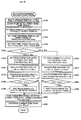
- the method includes the steps of (a) adjusting the rotational speed of the first or second motor corresponding to the other of the first and second elements so as to enable the connection between the other of the first and second element and the drive shaft in response to a satisfaction of a predetermined change speed state shift condition while the change speed transmission connects the one of the first and second elements with the drive shaft, the internal combustion engine is operated and the first and second motors are driven and controlled, (b) connecting the other of the first and second elements with the drive shaft by the change speed transmission, (c) transferring power between the first and second motors while the change speed transmission connects both of the first and second elements with the drive shaft so as to make the first and second motors respectively output power required when only the other of the first and second elements is connected with the drive shaft, and (d) disconnecting the one of the first and second elements from the drive shaft by the change speed transmission.
- both of the first and second elements are once connected with the drive shaft at Step (b) after the rotational speed adjustment process of Step (a) when the change speed transmission connects the one of the first and second elements with the drive shaft. Then, the other of the first and second elements is disconnected from the drive shaft at Step (d) after the power transfer process of Step (c).
- the power output apparatus appropriately changes connection states between the drive shaft and first and second elements of the power distribution integration mechanism, thereby improving transmission efficiency of power in a wider driving region.
- torque commands of the internal combustion engine, the first and second motors may be set so as to ensure power equivalent to the power demand required for the drive shaft while Steps (a)-(b) are performed.
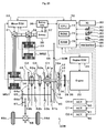
- Fig. 1 is a schematic block diagram of a hybrid vehicle 20 according to one embodiment of the invention.
- the hybrid vehicle 20 shown in Fig. 1 is constructed as a rear-wheel drive vehicle and includes an engine 22 located in a front portion of the vehicle body, a power distribution integration mechanism 40 connected to a crankshaft (engine shaft) 26 of the engine 22, a motor MG1 having power generation capability and linked with the power distribution integration mechanism 40, a motor MG2 having power generation capability and linked with the power distribution integration mechanism 40 to be coaxial with the motor MG1, a transmission 60 that transmits power from the power distribution integration mechanism 40 to a drive shaft 67 while changing a rotational speed, and a hybrid electronic control unit (hereafter referred to as "hybrid ECU”) 70 configured to control operations of the whole hybrid vehicle 20.
- hybrid ECU hybrid electronice control unit
- the engine 22 is an internal combustion engine that receives a supply of a hydrocarbon fuel, such as gasoline or light oil, and outputs power.
- the engine 22 is under control of an engine electronic control unit (hereafter referred to as "engine ECU") 24 and is subjected to, for example, a fuel injection control, an ignition control, and an intake air control.
- engine ECU 24 inputs diverse signals from various sensors that are provided for the engine 22 to measure and detect operating states of the engine 22, for example, a crank position sensor (not shown) mounted on the crankshaft 26.
- the engine ECU 24 establishes communication with the hybrid ECU 70 to drive and control the engine 22 in response to control signals from the hybrid ECU 70 and with reference to the diverse signals from the various sensors and to output data regarding the operating states of the engine 22 to the hybrid ECU 70 according to the requirements.
- the motors MG1 and MG2 are constructed as synchronous motor generators of an identical specification that can be operated both as a generator and as a motor.
- the motors MG1 and MG2 receive and supply electric power to a battery 35 or a secondary cell via inverters 31 and 32.
- Power lines 39 connecting the battery 35 with the inverters 31 and 32 are structured as a common positive bus and a negative bus shared by the inverters 31 and 32.
- Such connection enables electric power generated by one of the motors MG1 and MG2 to be consumed by the other motor MG2 or MG1.
- the battery 35 may thus be charged with surplus electric power generated by either of the motors MG1 and MG2, while being discharged to supplement insufficient electric power.
- the battery 35 is neither charged nor discharged upon the balance of the input and output of electric powers between the motors MG1 and MG2. Both the motors MG1 and MG2 are driven and controlled by a motor electronic control unit (hereafter referred to as "motor ECU") 30.
- the motor ECU 30 inputs various signals required for driving and controlling the motors MG1 and MG2, for example, signals representing rotational positions of rotors in the motors MG1 and MG2 from rotational position detection sensors 33 and 34 and signals representing phase currents to be applied to the motors MG1 and MG2 from current sensors (not shown).
- the motor ECU 30 outputs switching control signals to the inverters 31 and 32.
- the motor ECU 30 executes a rotational speed computation routine (not shown) to compute rotational speeds Nm1 and Nm2 of the rotors of the motors MG1 and MG2 from the signals output from the rotational position detection sensors 33 and 34.
- the motor ECU 30 establishes communication with the hybrid ECU 70 to drive and control the motors MG1 and MG2 in response to control signals received from the hybrid ECU 70 and to output data regarding operating states of the motors MG1 and MG2 to the hybrid ECU 70 according to the requirements.
- the battery 35 is under control and management of a battery electronic control unit (hereafter referred to as "battery ECU") 36.
- the battery ECU 36 inputs various signals required for management and control of the battery 35, for example, an inter-terminal voltage from a voltage sensor (not shown) located between terminals of the battery 35, a charge-discharge current from a current sensor (not shown) located in the power line 39 connecting with an output terminal of the battery 35, and a battery temperature Tb from a temperature sensor 37 attached to the battery 35.
- the battery ECU 36 outputs data regarding operating states of the battery 35 by communication to the hybrid ECU 70 and to the engine ECU 24 according to the requirements.
- the battery ECU 36 calculates a remaining charge amount or a state of charge SOC of the battery 35 based on an integrating value the charge-discharge current measured by the current sensor and calculates a charge-discharge power demand Pb* of the battery 35 based on the computed state of charge SOC.
- the battery ECU 36 also sets an input limit Win as an allowable charging power to be charged into the battery 35 and an output limit Wout as an allowable discharging power to be discharged from the battery 35, based on the computed state of charge SOC and the measured battery temperature Tb.
- the input and output limits Win and Wout of the battery 35 are set by setting base values depending on the battery temperature Tb and setting an input limit correction coefficient and an output limit correction coefficient based on the state of charge SOC of the battery 35, and then multiplying the set base value of the input and output limits Win and Wout by the set correction coefficient.
- the power distribution integration mechanism 40 is housed within a non-illustrated transmission case (casing) together with the motors MG1 and MG2 and the transmission 60 and is arranged apart from the engine 22 by a predetermined distance to be coaxial with the crankshaft 26.
- the power distribution integration mechanism 40 of the embodiment is a double pinion planetary gear mechanism and includes a sun gear 41 that is an external gear, a ring gear 42 that is an internal gear arranged concentrically with the sun gear 41, and a carrier 45 that supports at least one set of two pinion gears 43 and 44 intermeshing with each other so as to allow both their revolutions and their rotations on their axes.
- the sun gear 41 (second element), the ring gear 42 (third element), and the carrier 45 (first element) are designed as elements of differential rotations.
- the gear ratio p of the power distribution integration mechanism 40 may otherwise be selected in a range of, for example, 0.4 to 0.6.
- the sun gear 41 or the second element of the power distribution integration mechanism 40 is connected with the motor MG1 (more specifically with its hollow rotor) or a second motor via a hollow sun gear shaft 41a extended from the sun gear 41 in a direction opposite to the engine 22 (that is, toward a rear portion of the vehicle body) and a hollow first motor shaft 46.
- the carrier 45 or the first element is connected with the motor MG2 (more specifically with its hollow rotor) or a first motor via a hollow second motor shaft 55 extended to toward the engine 22.
- the ring gear 42 or the third element is connected with the crankshaft 26 of the engine 22 via a ring gear shaft 42a extended to pass through the second motor shaft 55 and the motor MG2, as well as a damper 28.
- a clutch C0 (connecting-disconnecting device) is disposed between the sun gear shaft 41a and the first motor shaft 46 to allow a connection (drive source-element connection) between the sun gear shaft 41a and the first motor shaft 46 and a release of the connection.
- the clutch C0 is constructed as a dog clutch including a movable engagement member that is capable of engaging with both an engagement portion secured to the sun gear shaft 41a and an engagement portion secured to the first motor shaft 46 and is moved back and forth in an axial direction of the sun gear shaft 41a and the first motor shaft 46 by an electromagnetic, electric, or hydraulic actuator 90.
- a carrier shaft (connecting shaft) 45a is extended from the carrier 45 of the power distribution integration mechanism 40 in the direction opposite to the engine 22 (toward the rear portion of the vehicle body).
- the carrier shaft 45a passes through the hollow sun gear shaft 41a and the hollow first motor shaft 46, and is connected with the transmission 60.
- the power distribution integration mechanism 40 is arranged coaxially with the motors MG1 and MG2 and is located between the motors MG1 and MG2 coaxially arranged with each other.
- the engine 22 is arranged coaxially with the motor MG2 and is located to oppose the transmission 60 across the power distribution integration mechanism 40.
- the engine 22, the motor MG2, the power distribution integration mechanism 40, the motor MG1, and the transmission 60 as constituents of the power output apparatus are thus arranged in this sequence from the forward to the rearward of the vehicle body. This arrangement reduces the size of the power output apparatus to be suitable for mounting on the rear-wheel drive hybrid vehicle 20.
- the transmission 60 is configured as a parallel-shaft type automatic transmission capable of setting a change speed state (speed ratio) in a plurality of stages and includes a first counter drive gear 61a and a first counter driven gear 61b constituting a first gear train, a second counter drive gear 62a and a second counter driven gear 62b constituting a second gear train, a third counter drive gear 63a and a third counter driven gear 63b constituting a third gear train, a fourth counter drive gear 64a and a fourth counter driven gear 64b constituting a fourth gear train, a counter shaft 65 to which each of the counter driven gears 61b to 64b and a gear 65b are fixed, clutches C1 and C2, a gear 66a attached to the drive shaft 67, a reverse gear train (not shown) and the like (hereafter the "counter drive gear” and the "counter driven gear” are simply referred to as a "gear” as appropriate).
- a gear ratio or the speed ratio G(1) of the first gear train
- the first gear 61a of the first gear train is held by the carrier shaft 45a extended from the carrier 45 or the first element of the power distribution integration mechanism 40 rotatably and immovably in the axial direction and always engages with the first gear 61b fixed to the counter shaft 65.
- the third gear 63a of the third gear train is held by the carrier shaft 45a rotatably and immovably in the axial direction and always engages with the third gear 63b fixed to the counter shaft 65.
- the clutch C1 is arranged on the carrier shaft 45a side (counter drive gear side).
- the clutch C1 can selectively fix either one of the first gear 61a (first gear train) and the third gear 63a (third gear train) to the carrier shaft 45a and rotatably release both the first gear 61a and the third gear 63a with respect to the carrier shaft 45a.
- the clutch C1 is constructed as a dog clutch that is moved back and forth in an axial direction of the sun gear shaft 41a and the like by an electromagnetic, electric, or hydraulic actuator 91 so as to connect an engagement portion secured to the carrier shaft 45a with either one of an engagement portion secured to the first gear 61a and the an engagement portion secured to the third gear 63a.
- the gears 61a, 61b of the first gear train, the gears 63a, 63b of the third gear train, and the clutch C1 constitute a first transmission mechanism of the transmission 60.
- the second gear 62a of the second gear train is held rotatably and immovably in the axial direction by the first motor shaft 46 that can be connected with the sun gear 41 or the second element of the power distribution integration mechanism 40 through the clutch C0 and always engages with the second gear 62b secured to the counter shaft 65.
- the fourth gear 64a of the fourth gear train is also held rotatably and immovably in the axial direction by the first motor shaft 46 and always engages with the fourth gear 64b secured to the counter shaft 65.
- the clutch C2 is arranged on the first motor shaft 46 side (counter drive gear side).
- the clutch C2 can selectively fix either one of the second gear 62a (second gear train) and the fourth gear 64a (fourth gear train) to the first motor shaft 46 and rotatably release both the second gear 62a and the fourth gear 64a with respect to the first motor shaft 46.
- the clutch C2 is also constructed as a dog clutch that is moved back and forth in an axial direction of the sun gear shaft 41a and the like by an electromagnetic, electric, or hydraulic actuator 92 so as to connect an engagement portion secured to the first motor shaft 46 with either one of an engagement portion secured to the second gear 62a and the an engagement portion secured to the fourth gear 64a.
- the gears 62a, 62b of the second gear train, the gears 64a, 64b of the fourth gear train, and the clutch C2 constitute a second transmission mechanism of the transmission 60.
- the power transmitted from the carrier shaft 45a or the first motor shaft 46 to the counter shaft 65 is transmitted to the drive shaft 67 through the gears 65b, 66b (in the embodiment, a gear ratio between the gears 65b and 66b is "1:1") and is output to rear wheels 69a, 69b or drive wheels in the end through a differential gear 68.
- the rotational speed of the gear 64a idling before being fixed to the first motor shaft 46 by the clutch C2 is lower than the rotational speed of the gear 64b on the corresponding counter shaft 65 side with regard to the second transmission mechanism including the fourth gear train with a smaller reduction ratio.
- the dog of the gear 64a and the dog of the first motor shaft 46 can be engaged with each other with a smaller loss by disposing at least the clutch C2 on the first motor shaft 46 side.
- the clutch C1 may be provided on the counter shaft 65 side.
- the power from the carrier shaft 45a can be transmitted to the drive shaft 67 through the first gear 61a (first gear train) or the third gear 63a (third gear train) and the counter shaft 65 by disengaging the clutch C2 and fixing either one of the first gear 61a (first gear train) and the third gear 63a (third gear train) to the carrier shaft 45a by the clutch C1.
- the power from the first motor shaft 46 can be transmitted to the drive shaft 67 through the second gear 62a (second gear train) or the fourth gear 64a (fourth gear train) and the counter shaft 65 by engaging the clutch C0 and disengaging the clutch C1 and by fixing either one of the second gear 62a (second gear train) and the fourth gear 64a (fourth gear train) to the first motor shaft 46 by the clutch C2.
- first change speed state first speed
- second change speed state second speed
- third change speed state third speed
- fourth gear train fourth gear train
- the hybrid ECU 70 is constructed as a microprocessor including a CPU 72, a ROM 74 that stores processing programs, a RAM 76 that temporarily stores data, a timer 78 configured to perform a time measurement process in response to a time measurement command, a non-illustrated input-output port, and a non-illustrated communication port.
- the hybrid ECU 70 receives various inputs via the input port: an ignition signal from an ignition switch (start switch) 80, a shift position SP from a shift position sensor 82 that detects the current position of a shift lever 81, an accelerator opening Acc from an accelerator pedal position sensor 84 that measures a depression amount of an accelerator pedal 83, a brake pedal position BP from a brake pedal position sensor 86 that measures a depression amount of a brake pedal 85, and a vehicle speed V from a vehicle speed sensor 87.
- the hybrid ECU 70 communicates with the engine ECU 24, the motor ECU 30, and the battery ECU 36 via the communication port to transmit diverse control signals and data to and from the engine ECU 24, the motor ECU 30, and the battery ECU 36, as mentioned previously.
- the hybrid ECU 70 also controls the clutch C0, the actuators 90-92 of the clutch C1, C2 includes in the transmission 60.
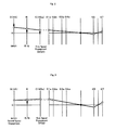
- an S-axis represents a rotational speed of the sun gear 41 in the power distribution integration mechanism 40 (equivalent to a rotational speed Nm1 of the motor MG1 or the first motor shaft 46).
- An R-axis represents a rotational speed of the ring gear 42 in the power distribution integration mechanism 40 (equivalent to a rotational speed Ne of the engine 22).
- a C-axis represents a rotational speed of the carrier 45 in the power distribution integration mechanism 40 (equivalent to a rotational speed of the carrier shaft 45a and the ring gear 52 of the reduction gear mechanism 50).
- a 61a-axis to 64a-axis, 65-axis and 67-axis respectively represent rotational speeds of the first gear 61a to fourth gear 64a, the counter shaft 65 and the drive shaft 67.
- the clutch C2 When the clutch C2 is disengaged and the first gear 61a (first gear train) is fixed to the carrier shaft 45a by the clutch C1 during a drive of the hybrid vehicle 20 with an engagement of the clutch C0 and an operation of the engine 22, as shown in Fig. 2 , the power from the carrier shaft 45a can be speed-changed (reduced) in accordance with the speed ratio of the first gear train (first gears 61a, 61b) and outputted to the drive shaft 67. Also, as shown in Fig.
- the second gear 62a (second gear train) can be fixed to the first motor shaft 46 by the clutch C2 while the clutch C1 fixes the first gear 61a (first gear train) to the carrier shaft 45a by rotationally synchronizing the first motor shaft 46 (sun gear 41) and the second gear 62a that always engages with the second gear 62b secured to the counter shaft 65 according to a change in the vehicle speed V (rotational speed of the drive shaft 67) in the first change speed state.
- V rotational speed of the drive shaft 67
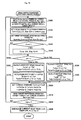
- the rotational speeds of the sun gear 41 (motor MG1), the ring gear 42 (engine 22) and the carrier 45 (motor MG2) in the 1 st speed-2 nd speed simultaneous engagement state depends on the speed ratio G(1) and G(2) of the transmission 60 and the gear ratio p of the power distribution integration mechanism 40 at each vehicle speed.
- the clutch C1 is disengaged in the 1 st speed-2 nd speed simultaneous engagement state shown in Fig. 3 , as shown by a two-dot chain line in Fig.
- the third gear 63a (third gear train) can be fixed to the carrier shaft 45a by the clutch C1 while the clutch C2 fixes the second gear 62a (second gear train) to the first motor shaft 46 by rotationally synchronizing the carrier shaft 45a (carrier 45) and the third gear 63a that always engages with the third gear 63b secured to the counter shaft 65 according to a change in the vehicle speed V in the second change speed state.
- a state to connect the sun gear 41 or the second element of the power distribution integration mechanism 40 with the drive shaft 67 by the second gear train of the transmission 60 and to connect the carrier 45 or the first element with the drive shaft 67 by the third gear train of the transmission 60 Fig.
- the rotational speeds of the sun gear 41 (motor MG1), the ring gear 42 (engine 22) and the carrier 45 (motor MG2) in the 2 nd speed-3 rd speed simultaneous engagement state depends on the speed ratio G(2) and G(3) of the transmission 60 and the gear ratio p of the power distribution integration mechanism 40 at each vehicle speed.
- the clutch C2 is disengaged in the 2 nd speed-3 rd speed simultaneous engagement state shown in Fig. 5 , as shown by a two-dot chain line in Fig.
- the fourth gear 64a (fourth gear train) can be fixed to the first motor shaft 46 by the clutch C2 while the clutch C1 fixes the third gear 63a (third gear train) to the carrier shaft 45a by rotationally synchronizing the first motor shaft 46 (sun gear 41) and the fourth gear 64a that always engages with the fourth gear 64b secured to the counter shaft 65 according to a change in the vehicle speed V in the third change speed state.
- the carrier 45 or the first element of the power distribution integration mechanism 40 with the drive shaft 67 by the third gear train of the transmission 60 and to connect the sun gear 41 or the second element with the drive shaft 67 by the fourth gear train of the transmission 60 ( Fig.
- the rotational speeds of the sun gear 41 (motor MG1), the ring gear 42 (engine 22) and the carrier 45 (motor MG2) in the 3 rd speed-4 th speed simultaneous engagement state depends on the speed ratio G(3) and G(4) of the transmission 60 and the gear ratio p of the power distribution integration mechanism 40 at each vehicle speed.
- the clutch C1 is disengaged in the 3 rd speed-4 th speed simultaneous engagement state shown in Fig. 7 , as shown by a two-dot chain line in Fig.
- the motors MG1 and MG2 may be driven and controlled to make the motor MG2, which is connected with the carrier 45 of the power distribution integration mechanism 40 working as the output element, function as the motor and to make the motor MG1, which is connected with the sun gear 41 working as the reactive element, function as the generator.
- the power distribution integration mechanism 40 distributes the power from the engine 22 input via the ring gear 42 at its gear ratio ⁇ into the sun gear 41 and the carrier 45, while integrating the power from the engine 22 with the power from the motor MG2 functioning as the motor and outputting the integrated power to the carrier 45.
- first torque conversion mode a mode of making the motor MG1 function as the generator and making the motor MG2 function as the motor.
- the power from the engine 22 goes through torque conversion by means of the power distribution integration mechanism 40 and the motors MG1 and MG2 and is then output to the carrier 45.
- the ratio of the rotational speed Ne of the engine 22 to the rotational speed of the carrier 45 or the output element is varied continuously in a stepless manner by controlling the rotational speed of the motor MG1.
- Fig. 9 is an explanatory view exemplifying an alignment chart showing a state of torques and rotational speeds of elements included in the power distribution integration mechanism 40 in the first torque conversion mode.
- ⁇ represents the gear ratio of the power distribution integration mechanism 40 (number of teeth of the sun gear 41 / number of teeth of the ring gear 42).
- Thick arrows on the axes represent torques applied to the corresponding elements. Upward arrows show application of positive torques and downward arrows show application of negative torques (these definitions are similarly applied to Figs. 2 to 8 and Figs. 10 and 11 ).
- the motors MG1 and MG2 may be driven and controlled to make the motor MG1, which is connected with the sun gear 41 of the power distribution integration mechanism 40 working as the output element, function as the motor and to make the motor MG2, which is connected with the carrier 45 working as the reactive element, function as the generator.
- the power distribution integration mechanism 40 distributes the power from the engine 22 input via the ring gear 42 at its gear ratio ⁇ into the sun gear 41 and the carrier 45, while integrating the power from the engine 22 with the power from the motor MG1 functioning as the motor and outputting the integrated power to the sun gear 41.
- a mode of making the motor MG2 function as the generator and making the motor MG1 function as the motor is referred to as "second torque conversion mode".
- the power from the engine 22 goes through torque conversion by means of the power distribution integration mechanism 40 and the motors MG1 and MG2 and is then output to the sun gear 41.
- the ratio of the rotational speed Ne of the engine 22 to the rotational speed of the sun gear 41 as the output element is varied continuously in a stepless manner by controlling the rotational speed of the motor MG2.
- Fig. 10 is an explanatory view exemplifying an alignment chart showing a state of torques and rotational speeds of elements included in the power distribution integration mechanism 40 in the second torque conversion mode.
- the first torque conversion mode and the second torque conversion mode are alternately switched over with a change of the change speed state (speed ratio) in the transmission 60.
- Such switchover prevents the rotational speed Nm1 or Nm2 of the motor MG1 or MG2 functioning as the generator from having a negative value with an increase in rotational speed Nm2 or Nm1 of the motor MG2 or MG1 functioning as the motor. This effectively prevents the occurrence of power circulation in the first torque conversion mode, as well as the occurrence of power circulation in the second torque conversion mode.
- the power circulation in the first torque conversion mode is triggered by the negative rotational speed of the motor MG1 and causes the motor MG2 to consume part of the power output to the carrier shaft 45a and generate electric power, while causing the motor MG1 to consume the electric power generated by the motor MG2 and output driving power.
- the power circulation in the second torque conversion mode is triggered by the negative rotational speed of the motor MG2 and causes the motor MG1 to consume part of the power output to the first motor shaft 46 and generate electric power, while causing the motor MG2 to consume the electric power generated by the motor MG1 and output driving power.
- Such prevention of the power circulation desirably improves the power transmission efficiency in a wider drive range.
- the prevention of the power circulation also reduces the maximum required rotational speeds of the motors MG1 and MG2 and thereby enables size reduction of the motors MG1 and MG2.
- the output power of the engine 22 can be mechanically (directly) transmitted to the drive shaft 67 at the fixed speed ratios (fixed speed ratios ⁇ 1- ⁇ 3) uniquely set for the 1 st speed-2 nd speed simultaneous engagement state, the 2 nd speed-3 rd speed simultaneous engagement state, and the 3rd speed fixing state.
- This desirably increases the potential for mechanical output of the power from the engine 22 to the drive shaft 67 without conversion into electrical energy and thereby further enhances the power transmission efficiency in the wider drive range.
- the relatively large reduction gear ratio between the engine and a drive shaft increases the potential for conversion of the engine output power into electrical energy. This undesirably decreases the power transmission efficiency and tends to cause heat generation in the motors MG1 and MG2.
- the simultaneous engagement mode described above is thus especially advantageous for the relatively large reduction gear ratio between the engine 22 and the drive shaft 67.
- the motor drive mode includes a clutch engagement one-motor drive mode, a clutch release one-motor drive mode, and a two-motor drive mode.
- the clutch C0 In the clutch engagement one-motor drive mode, the clutch C0 is engaged, and the first gear 61a of the first gear train or the third gear 63a of the third gear train of the transmission 60 is fixed to the carrier shaft 45a to allow the power output from only the motor MG2, or the second gear 62a of the second gear train or the fourth gear 64a of the fourth gear train of the transmission 60 is fixed to the first motor shaft 46 to allow the power output from only the motor MG1.
- the clutch C0 In the clutch engagement one-motor drive mode, the clutch C0 is set to connect the sun gear 41 of the power distribution integration mechanism 40 with the first motor shaft 46.
- the motor MG1 or MG2 in the state of no power output thus follows the motor MG2 or MG1 in the state of power output to run idle as shown by the broken line in Fig. 11 .
- the clutch release one-motor drive mode the clutch C0 is disengaged, and the first gear 61a of the first gear train or the third gear 63a of the third gear train of the transmission 60 is fixed to the carrier shaft 45a to allow the power output from only the motor MG2, or the second gear 62a of the second gear train or the fourth gear 64a of the fourth gear train of the transmission 60 is fixed to the first motor shaft 46 to allow the power output from only the motor MG1.
- the clutch C0 is disengaged to disconnect the sun gear 41 from the first motor shaft 46.
- the one-dot chain line and the two-dot chain line in Fig. 11 such disconnection effectively avoids a following rotation of the crankshaft 26 of the engine 22 that is stopped, as well as a following rotation of the motor MG1 or MG2 in the state of no power output, thereby preventing a decrease in power transmission efficiency.
- the clutch C0 is disengaged, and at least one of the motors MG1 and MG2 is driven and controlled while the transmission 60 is set in the 1 st speed-2 nd speed simultaneous engagement state, the 2 nd speed-3 rd speed simultaneous engagement state or the 3 rd speed-4 th speed simultaneous engagement state by means of the clutch C1 and C2.
- Such setting and drive control effectively avoids the following rotation of the engine 22 and enables the power output from both the motors MG1 and MG2 and transmission of a large driving power to the drive shaft 67 in the motor drive mode.
- This two-motor drive mode is especially suitable for a hill start and ensures the favorable towing performance during the motor drive of the hybrid vehicle 20.
- the change speed state (speed ratio) of the transmission 60 can be readily changed to enable the efficient power transmission to the drive shaft 67 when the clutch release one-motor drive mode is selected.
- the drive mode from the clutch release one-motor drive mode to the two-motor drive mode that is, the 1 st speed-2 nd speed simultaneous engagement state, the 2 nd speed-3 rd speed simultaneous engagement state or the 3 rd speed-4 th speed simultaneous engagement state by synchronizing the rotational speed of the motor MG1 that is stopped with the rotational speed of the second gear 62a of the second gear train of the fourth gear of the fourth gear train and fixing the second gear 62a or the fourth gear 64a to the first motor shaft 46 when the first gear 61a of the first gear train or the third gear 63a of the third gear train of the transmission 60 is fixed to the carrier shaft 45a to allow the power output from only the motor MG2 in the clutch release one-motor drive mode in the clutch release one-motor drive mode.
- the output power of the motor MG1 can be transmitted to the drive shaft 67 via the second gear train or the fourth gear train of the transmission 60 by disengaging the clutch C1 of the transmission 60 to allow the power output from only the motor MG1.
- the transmission 60 is used to change the rotational speed of the carrier shaft 45a and the first motor shaft 46 and amplify the torque in the motor drive mode, thereby desirably reducing the maximum required torques of the motors MG1 and MG2 and enabling size reduction of the motors MG1 and MG2.
- the simultaneous engagement mode or the two-motor drive mode is once performed when the speed ratio of the transmission 60 is changed during the motor drive.
- the motor MG1 or MG2 In response to an increase of a driving force demand or a decrease of the state of charge SOC of the battery 35 in the clutch engagement one-motor drive mode, the motor MG1 or MG2 to be made into the state of no power output corresponding to the setting of the speed ratio in the transmission 60 is driven and controlled to crank and start up the engine 22.
- FIGs. 12 to 16 a concrete explanation is given on an operation of the hybrid vehicle 20 upon changing the change speed state (speed ratio) of the transmission during the drive of the hybrid vehicle 20 with the engagement of the clutch C0 and the operation of the engine 22.
- Figs. 12 and 13 are flowcharts illustrating an example of a drive control routine executed by a hybrid ECU 70 at preset time intervals (for example, at ever several msec) during the drive of the hybrid vehicle 20 with an engagement of the clutch C0 and the operation of the engine 22.
- an input process of data required for control such as the accelerator opening Acc from the accelerator pedal position sensor 84, the vehicle speed V from the vehicle speed sensor 87, the rotational speed Ne of the engine 22 (crankshaft 26), the rotational speeds Nm1, Nm2 of the motors MG1, MG2, the charge-
- the rotational speed Ne of the engine 22 is calculated based on a signal from a crank position sensor (not shown) mounted on the crank shaft 26 by the engine ECU 24 and is input from the engine ECU 24 by communication.
- the rotation speeds Nm1 and Nm2 of the motors MG1 and MG2 are input from the motor ECU 30 by communication.
- the charge-discharge power demand Pb* (where positive values represent discharge demands) and the input and output limit Win and Wout of the battery 35 are input from the battery ECU 36 by communication.
- the current speed n indicates one gear train connecting the carrier shaft 45a or the first motor shaft 46 with the drive shaft 67 among the first to fourth gear trains of the transmission.
- the current speed n is stored in a predetermined memory region of the RAM 76 when any one of the first to fourth gear trains connects the carrier shaft 45a or the first motor shaft 46 with the drive shaft 67.
- the target speed n* and the shift change flag Fsc are set through a change speed determination routing that is separately executed by the hybrid ECU 70.
- the hybrid ECU 70 sets the shift change flag Fsc to value "0" when the change speed state (speed ratio) is maintained and sets the shift change flag Fsc to value "1" when a predetermined change speed state shift condition is satisfied.
- the change speed state shift condition relates to the vehicle speed V (rotational speed of the drive shaft 67), the accelerator opening Acc and the like and is previously defined in consideration of the transmission efficiency between the engine 22 and the drive shaft 67, performances and heating characteristics of the motors MG1 and MG2, gear ratios G(1)-G(4) of the transmission 60.
- the hybrid ECU 70 sets the target speed n* to the sum of the current speed n and value "1" while the hybrid vehicle is accelerated in accordance with the vehicle speed V, the accelerator opening Acc and the like, and sets the target speed n* to a difference obtained by subtracting value "1" from the current speed n while the hybrid vehicle is decelerated in accordance with the vehicle speed V, the accelerator opening Acc and the like.
- the COU 72 sets a torque demand Tr* to be outputted to the drive shaft 67 based on the input accelerator opening Acc and the input vehicle speed V, and sets a power demand Pe* required for the engine 22 (Step S110).
- the torque demand Tr* corresponding to the given accelerator opening Acc and the given vehicle speed V is derived from a torque demand setting map previously stored in the ROM 74 and defining a relationship between the accelerator opening Acc, the vehicle speed V and the torque demand Tr*.
- Fig. 14 illustrates an example of the torque demand setting map.
- the power demand Pe* is calculated as the sum of a product of the set torque demand Tr* and a rotational speed of the drive shaft 67 obtained by multiplying the vehicle speed V by a predetermined conversion factor k, the charge-discharge power demand Pb*, and a potential loss Loss (sum of a mechanical loss in the torque conversion of the power distribution integration mechanism 40 and an electrical loss in driving the motors MG1 and MG2).
- the drive shaft 67 may be provided with a rotational speed sensor and the rotational speed of the drive shaft 67 measured by the rotational speed sensor may be used for a calculation of the power demand Pe* instead of a product of the vehicle speed V and the predetermined conversion factor k.
- the CPU 72 determines whether or not the shift change flag Fsc input at Step S100 is value "0" (Step S120).
- the CPU 72 sets a target rotational speed Ne* and a target torque Te* of the engine 22 based on the power demand Pe* set at Step S110 (Step S130).
- the target rotational speed Ne* and the target torque Te* are set based on a predetermined operation curve for operating the engine 22 with high efficiency and the power demand Pe*.
- FIG. 15 is illustrates the operation curve of the engine 22 and a correlation curve (constant power curve) between the engine rotational speed Ne and an engine torque Te.
- the target rotational speed Ne* and the target torque Te* can be obtained from an intersection between the operation curve and the correlation curve indicating a constant power demand Pe* (NexTe).
- the CPU 72 determines whether the current speed n input at Step S100 is value "1", “2", “3” or “4" (the first gear train, the second gear train, the third gear train or the fourth gear train) (Step S140).
- the current speed n is value "1" or "3”
- the transmission 60 connects the carrier shaft 45a with the drive shaft 67.
- the CPU 72 calculates a target rotational speed Nm1* of the motor MG1 based on the target rotational speed Ne* set at Step S130, the rotational speed (Nm2) of the carrier shaft 45a (carrier 45) and the gear ratio p of the power distribution integration mechanism 40 according to Equation (1) given below.
- the Equation (1) is a dynamic relational expression of respective rotational elements included in the power distribution integration mechanism 40 and is readily obtained from the alignment chart of Fig. 9 .
- the Equation (2) is a relational expression of feedback control to drive and rotate the motor MG1 at the target rotational speed Nm1* .
- 'k11' in a second term and 'k12' in a third term on the right side respectively denote a gain of the proportional term and a gain of the integral term.
- the CPU 72 calculates torque restrictions Tmin and Tmax as allowable minimum and maximum torques to be output from the motor MG2 by dividing a deviation between the output limit Wout or the input limit Win of the battery 35 and power consumption of the motor MG1 that is a product of the torque command Tm1* and the current rotational speed Nm1 of the motor MG1 by the rotational speed Nm2 of the motor MG2 (Step S160).
- the CPU 72 calculates a temporary motor torque Tm2tmp as torque to be output from the motor MG2 based on the torque demand Tr*, the torque command Tm1*, the gear ratio G(n) of the gear train corresponding to the current speed n and the gear ratio p of the power distribution integration mechanism 40 according to Equation (3) (Step S170).
- the Equation (3) is readily obtained from the alignment chart of Fig. 9 .
- the CPU 72 sets a torque command Tm2* of the motor MG2 to a value obtained by limiting the calculated temporary motor torque Tm2tmp by the lower and the upper torque restrictions Tmin and Tmax set at Step S160 (Step S180).
- Step S190 Setting the torque command Tm2* of the motor MG2 in this manner restricts the torque to be output to the carrier shaft 45a in the range of the input limit Win and the output limit Wout of the battery 35.
- the engine ECU 24 receives the target rotational speed Ne* and the target torque Te* and performs control to obtain the target rotational speed Ne* and the target torque Te*.
- the motor ECU 30 receives the torque commands Tm1* and Tm2* and performs switching control of switching elements included in the respective inverters 41 and 42 so that the motor MG1 is driven in accordance with the torque command Tm1* and the motor MG2 is driven in accordance with the torque command Tm2*.
- the transmission 60 connects the first motor shaft 46 with the drive shaft 67.
- the CPU 72 calculates a target rotational speed Nm2* of the motor MG2 based on the target rotational speed Ne* set at Step S130, the rotational speed Nm1 of the motor MG1 matching with a rotational speed of the first motor shaft 46 (sun gear 41) and the gear ratio p of the power distribution integration mechanism 40 according to Equation (4) given below.
- CPU 72 sets the torque command Tm2* of the motor MG2 by calculation of below Equation (5) based on the calculated target rotational speed Nm2* and the current rotational speed Nm2 of the motor MG2 (Step S200).
- the Equation (4) is also the dynamic relational expression of respective rotational elements included in the power distribution integration mechanism 40 and is readily obtained from the alignment chart of Fig. 10 .
- the Equation (5) is the relational expression of feedback control to drive and rotate the motor MG2 at the target rotational speed Nm2*.
- 'k21' in the second term and 'k22' in the third term on the right side respectively denote the gain of the proportional term and the gain of the integral term.
- the CPU 72 calculates torque restrictions Tmin and Tmax as allowable minimum and maximum torques to be output from the motor MG1 by dividing a deviation between the output limit Wout or the input limit Win of the battery 35 and power consumption of the motor MG2 that is a product of the torque command Tm2* and the current rotational speed Nm2 of the motor MG2 by the rotational speed Nm1 of the motor MG1 (Step S210).
- the CPU 72 calculates a temporary motor torque Tm1tmp as torque to be output from the motor MG1 based on the torque demand Tr*, the torque command Tm2*, the gear ratio G(n) of the gear train corresponding to the current speed n and the gear ratio p of the power distribution integration mechanism 40 according to Equation (6) (Step S220).
- the Equation (6) is readily obtained from the alignment chart of Fig. 10 .
- the CPU 72 sets a torque command Tm1* of the motor MG1 to a value obtained by limiting the calculated temporary motor torque Tm1tmp by the lower and the upper torque restrictions Tmin and Tmax set at Step S210 (Step S230).
- Step S190 Setting the torque command Tm1* of the motor MG1 in this manner restricts the torque to be output to the first motor shaft 46 in the range of the input limit Win and the output limit Wout of the battery 35.
- the CPU 72 determines whether the current speed n input at Step S100 is value "1", "2", “3" or "4" (the first gear train, the second gear train, the third gear train or the fourth gear train) as shown in Fig. 13 (Step S240). When the current speed n is value "1" or "3”, the CPU 72 determines whether or not a predetermined flag F is value "0" (Step S250).
- the CPU 72 sets the flag F to value "1" (Step S260) and calculates a n th fixed speed ratio ⁇ (N) corresponding to the gear ratio p of the power distribution integration mechanism 40, the gear ratio G(n) of the gear train corresponding to the current speed n, and a gear ratio G(n*) of the gear train corresponding to the target speed n* as shown in the figure (Step S270).
- the value "N” is value "1", “2” or "3" that is settled corresponding to the current speed n and the target speed n*.
- the flag F has been set to value "1" at Step S260. Accordingly, processes of Steps S260 and S270 are skipped after a next execution of the routine because a negative determination is made at Step S250.
- the CPU 72 sets the target rotational speed Ne* and the target torque Te* (Step S280).
- the target rotational speed Ne* is set to a rotational speed of the engine 22 in an N th simultaneous engagement state corresponding to the rotational speed the drive shaft 67 (vehicle speed V) while considering that the current speed n is value "1" or "3" and the transmission 60 connects the carrier 45 (carrier shaft 45a) and the drive shaft 67.
- Step S280 the CPU 72 sets the target rotational speed Ne* of the engine 22 to a product of a quotient (rotational speed of the drive shaft 67) of the rotational speed of the motor MG2 input at Step S100 divided by the gear ratio G(n) of the gear train corresponding to the current speed n and the n th fixed speed ratio ⁇ (N) calculated at Step S270. Further, at Step S280, the CPU 72 sets the target torque Te* of the engine 22 to smaller one of a quotient of the power demand Pe* set at Step S110 divided by the target rotational speed Ne* and a rating toque Temax of the engine 22.
- the CPU 72 calculates the rotational speed of the motor MG1 corresponding to the rotational speed of the drive shaft 67 (vehicle speed V) in the N th simultaneous engagement state as the target rotational speed Nm1*, and sets the torque command Tm1* of the motor MG1 according to the above Equation (2) in order to rotationally synchronize the first motor shaft 46 (sun gear 41) and the second gear 62a of the second gear train or the fourth gear 64a of the fourth gear train corresponding to the target speed n* (Step S290).
- the target rotational speed Nm1* may be obtained by multiplying the quotient (rotational speed of the drive shaft 67) of the rotational speed of the motor MG2 input at Step S100 divided by the gear ratio G(n) of the gear train corresponding to the current speed n by the gear ratio G(n*) of the gear train corresponding to the target speed n*.
- Step S330 the CPU 72 determines whether or not an absolute value of a difference between the rotational speed Nm1 of the motor MG1 input at Step S100 and the target rotational speed Nm1* is equal to or less than a predetermined value ⁇ (Step S340).
- the CPU 72 When the absolute value of the difference is more than the predetermined value ⁇ , the CPU 72 returns to Step S100 to repeat the processes of and after Step S100. On the other hand, when the absolute value of the difference is equal to or less than the predetermined value ⁇ , the CPU 72 determined that the first motor shaft 46 (sun gear 41) is rotationally synchronized with the second gear 62a of the second gear train or the fourth gear 64a of the fourth gear train corresponding to the target speed n*. The CPU 72 sends a command signal to the actuator 92 of the clutch C2 so as to fix (engage) the second gear 62a or the fourth gear 64a (the second gear train or the fourth gear train) to (with) the first motor shaft 46 and sets the flag F to value "0" (Step S350). Then, the CPU 72 terminates the routine.
- the predetermined may be defined as a small value enough to determine that the rotational speed Nm1 substantially matches with the target rotational speed Nm1*.
- Step S360 the CPU 72 determines whether or not the predetermined flag F is value "0" (Step S360).
- the CPU 72 sets the flag F to value "1" (Step S370) and calculates the n th fixed speed ratio ⁇ (N) corresponding to the gear ratio p of the power distribution integration mechanism 40, the gear ratio G(n) of the gear train corresponding to the current speed n, and a gear ratio G(n*) of the gear train corresponding to the target speed n* as shown in the figure (Step S380).
- Step S380 the CPU 72 sets the target rotational speed Ne* and the target torque Te* (Step S390).
- the target rotational speed Ne* is set to a rotational speed of the engine 22 in the N th simultaneous engagement state corresponding to the rotational speed the drive shaft 67 (vehicle speed V) while considering that the current speed n is value "2" or "4" and the transmission 60 connects the sun gear 41 (first motor shaft 46) corresponding to the motor MG1 and the drive shaft 67.
- Step S390 the CPU 72 sets the target rotational speed Ne* of the engine 22 to a product of a quotient (rotational speed of the drive shaft 67) of the rotational speed of the motor MG1 input at Step S100 divided by the gear ratio G(n) of the gear train corresponding to the current speed n and the n th fixed speed ratio ⁇ (N) calculated at Step S380. Further, at Step S390, the CPU 72 sets the target torque Te* of the engine 22 to smaller one of the quotient of the power demand Pe* set at Step S110 divided by the target rotational speed Ne* and the rating toque Temax of the engine 22.
- the CPU 72 calculates the rotational speed of the motor MG2 corresponding to the rotational speed of the drive shaft 67 (vehicle speed V) in the N th simultaneous engagement state as the target rotational speed Nm2*, and sets the torque command Tm2* of the motor MG2 according to the above Equation (5) in order to rotationally synchronize the carrier 45a (carrier 45) and the first gear 61a of the first gear train or the third gear 63a of the third gear train corresponding to the target speed n* (Step S400).
- the target rotational speed Nm2* may be obtained by multiplying the quotient (rotational speed of the drive shaft 67) of the rotational speed of the motor MG1 input at Step S100 divided by the gear ratio G(n) of the gear train corresponding to the current speed n by the gear ratio G(n*) of the gear train corresponding to the target speed n*.
- Step S440 the CPU 72 executes the same processes as Steps S210-S230 at Steps S410-S430 so as to set the torque command Tm1* of the motor MG1 and sends the target rotational speed Ne* and the target torque Te* of the engine 22 to the engine ECU 24 and sends the torque commands Tm1* and Tm2* of the motors MG1 and MG2 to the motor ECU 30 (Step S440).
- Step S440 After a data sending process of Step S440, the CPU 72 determines whether or not an absolute value of a difference between the rotational speed Nm2 of the motor MG2 input at Step S100 and the target rotational speed Nm2* is equal to or less than a predetermined value ⁇ (Step S450).
- the CPU 72 When the absolute value of the difference is more than the predetermined value ⁇ , the CPU 72 returns to Step S100 to repeat the processes of and after Step S100. On the other hand, when the absolute value of the difference is equal to or less than the predetermined value ⁇ , the CPU 72 determined that the carrier shaft 45a (carrier 45) is rotationally synchronized with the first gear 61a of the first gear train or the third gear 63a of the third gear train corresponding to the target speed n*. The CPU 72 sends a command signal to the actuator 91 of the clutch C1 so as to fix (engage) the first gear 61a or the third gear 63a (the first gear train or the third gear train) to (with) the carrier shaft 45a and sets the flag F to value "0" (Step S350). Then, the CPU 72 terminates the routine.
- the transmission 60 connects the other of the sun gear 41 and the carrier 45 with the drive shaft 67 (Step S350) after a rotational speed adjustment process (Steps S240-S340 or S240 and S360-S440) of conforming the rotational speed of the motor MG1 or MG2 corresponding to the other of the sun gear 41 (first motor shaft 46) and the carrier 45 (carrier shaft 45a) that has not connected with the drive shaft 67 to the target rotational speed Nm1* or Nm2* based on the gear ratio G(1)-G(4) of the transmission 60 and the rotational speed of the drive shaft 67 (vehicle speed V).
- the first motor shaft 46 or the carrier shaft 45a can be appropriately connected with the drive shaft 67 by the gear train corresponding to the target speed n* while connecting the carrier shaft 45a or the first motor shaft 46 with the drive shaft 67 by the gear train corresponding to the current speed n and reducing the shock, thereby implementing the N th simultaneous engagement state corresponding to the current speed n and the target speed n*.
- a termination of the drive control routine of Figs. 12 and 13 after the process of Step S350, a simultaneous engagement state drive control routine shown in Fig. 16 is executed by the hybrid ECU 70.
- the simultaneous engagement state drive control routine of Fig. 16 will be described.
- the hybrid ECU 70 executes an input process of data required for control such as the accelerator opening Acc from the accelerator pedal position sensor 84, the vehicle speed V from the vehicle speed sensor 87, the rotational speed Ne of the engine 22, the rotational speeds Nm1, Nm2 of the motors MG1, MG2, the charge-discharge power demand Pb*, the input and output limits Win and Wout of the battery 35, the current speed n and the target speed n* and the like (Step S500) and sets the torque demand Tr* and the power demand Pe* as in the case of Step S110 in Fig. 12 (Step S510).
- Step S550 the CPU 72 determines whether the target speed n* input at Step S500 is value "1", "2", “3” or "4" (the first gear train, the second gear train, the third gear train or the fourth gear train) (Step S550).
- the CPU 72 sets a start point torque Tm1a to a motor torque demand of the motor MG1 based on the target torque Te* of the engine 22 set at Step S520 in a pre-change speed state before the N th simultaneous engagement state where the transmission 60 connects both the carrier shaft 45a and the first motor shaft 46 with the drive shaft 67, that is, in a state where only the carrier shaft 45a is connected with the drive shaft 67 by the first or third gear train corresponding to the current speed n (Step S560).
- the CPU 72 also sets a start point torque Tm2a to a motor torque demand of the motor MG2 based on the start point torque Tm1a (the target torque Te*), the torque demand Tr* set at Step S510 and the gear ratio G(n) of the gear train corresponding to the current speed n as shown in Equation (8) given below.
- the CPU 72 sets an end point torque Tm2b to a motor torque demand of the motor MG2 based on the target torque Te* of the engine 22 set at Step S520 in a post-change speed state after the N th simultaneous engagement state where the transmission 60 connects both the carrier shaft 45a and the first motor shaft 46 with the drive shaft 67, that is, in a state where only the first motor shaft 46 is connected with the drive shaft 67 by the second or fourth gear train corresponding to the target speed n* (Step S570).
- the CPU 72 also sets an end point torque Tm1b to a motor torque demand of the motor MG1 based on the end point torque Tm2b (the target torque Te*), the torque demand Tr* set at Step S510 and the gear ratio G(n*) of the gear train corresponding to the target speed n* as shown in Equation (10) given below.
- the CPU 72 sets a start point torque Tm2a to a motor torque demand of the motor MG2 based on the target torque Te* of the engine 22 set at Step S520 in a pre-change speed state before the N th simultaneous engagement state where the transmission 60 connects both the carrier shaft 45a and the first motor shaft 46 with the drive shaft 67, that is, in a state where only the first motor shaft 46 is connected with the drive shaft 67 by the second or fourth gear train corresponding to the current speed n (Step S580).
- the CPU 72 also sets a start point torque Tm1a to a motor torque demand of the motor MG1 based on the start point torque Tm2a (the target torque Te*), the torque demand Tr* set at Step S510 and the gear ratio G(n) of the gear train corresponding to the current speed n as shown in Equation (12) given below.
- the CPU 72 sets an end point torque Tm1b to a motor torque demand of the motor MG1 based on the target torque Te* of the engine 22 set at Step S520 in a post-change speed state after the N th simultaneous engagement state where the transmission 60 connects both the carrier shaft 45a and the first motor shaft 46 with the drive shaft 67, that is, in a state where only the carrier shaft 45a is connected with the drive shaft 67 by the first or third gear train corresponding to the target speed n* (Step S590).
- the CPU 72 also sets an end point torque Tm2b to a motor torque demand of the motor MG2 based on the end point torque Tm1b (the target torque Te*), the torque demand Tr* set at Step S510 and the gear ratio G(n*) of the gear train corresponding to the target speed n* in the post-change speed state as shown in Equation (14) given below.
- the CPU 72 executes calculations of Equations (15) and (16) given below based on the calculated start point torque Tm1a, Tm2a, the calculated end point torque Tm1b, Tm2b, an elapsed time t measured by the timer 78 and a predetermined transfer time ts so as to set the torque commands of the motors MG1 and MG2 (Step S600).
- Step S600 sets the torque commands Tm1* and Tm2* of the motors MG1 and MG2 so that output torques of the motors MG1 and MG2 gradually change from the start point torques to the end point torques within the torque transfer time ts.
- the torque transfer time ts is previously set to minimal time in consideration of characteristics of the motors MG1 and MG2 and a torque shock in the drive shaft 67.
- the CPU 72 After setting the torque commands Tm1* and Tm2*, the CPU 72 sends the target rotational speed Ne* and the target torque Te* of the engine 22 to the engine ECU 24 and sends the torque commands Tm1* and Tm2* of the motors MG1 and MG2 to the motor ECU 30 (Step S610).
- Step S610 the CPU 72 determines whether or not the elapsed time t measured by the timer 78 is equal to or more than the torque transfer time ts (Step S620). When the elapsed time t is less than the torque transfer time ts, the CPU 72 returns to Step S500 to repeat the processes of and after Step S500.
- Step S610 While repeatedly executing the processes from Step S500 to Step S610, the start point torques Tm1a and Tm2a that are the motor torque demands of the motors MG1 and MG2 in the pre-change speed state and the end point torques Tm1b and Tm2b that are the motor torque demands of the motors MG1 and MG2 in the post-change speed state are calculated every time the torque demand Tr* is set at Step S510.
- a transfer of power between the motors MG1 and MG2 based on the start point torques Tm1a and Tm2a and the end point torques Tm1b and Tm2b is executed so that the motors MG1 and MG2 respectively output torque required in the post-change speed state corresponding to the target speed n* when the torque transfer time ts is substantially elapsed after the start of the routine.
- the CPU 72 sends a command signal to the actuator 91 or 92 of the clutch C1 or C2 so as to disconnect the carrier shaft 45a or the first motor shaft 46 from the gear train corresponding to the current speed n and sets both the flag Fx and the shift change flag Fsc to value "0" (Step S630). Then, the CPU 72 terminates the routine.
- Tm ⁇ 1 * ts - t ⁇ Tm ⁇ 1 ⁇ a + t ⁇ Tm ⁇ 1 ⁇ b / ts
- Tm ⁇ 2 * ts - t ⁇ Tm ⁇ 2 ⁇ a + t ⁇ Tm ⁇ 2 ⁇ b / ts
- the hybrid vehicle 20 of the embodiment includes the transmission 60 configured to selectively connect either one or both of the carrier 45 (first element) and the sung gear 41 (second element) of the power distribution integration mechanism 40 with the drive shaft 67 and to transmit power from the carrier 45 and power from the sun gear 41 at the predetermined speed ratio G(1), G(3), or G(2), G(3) to the drive shaft 67.
- the hybrid vehicle 20 ensures torque equivalent to the set torque demand Tr* and connects the other of the carrier 45 and the sun gear 41 with the drive shaft 67 by the gear train corresponding to the target speed n* of the transmission 60 (Step S350 of Fig. 13 ) after the rotational speed adjustment process (Steps S240-S340 or S240 and S360-S450 of Fig.
- the hybrid vehicle 20 ensures torque equivalent to the set torque demand Tr* and releases the connection between the drive shaft 67 and the one of the sun gear 45 and the sun gear 41 by the gear train corresponding to the current speed n of the transmission 60 (Step S630 of Fig.
- Steps S500-S620 of Fig. 16 after the power transfer process (Steps S500-S620 of Fig. 16 ) of transferring power between the motors MG1 and MG2 while both of the carrier 45 and the sun gear 41 are connected with the drive shaft 67 by the gear train corresponding to the current speed n and the gear train corresponding to the target speed n* so as to make the motors MG1 and MG2 respectively output power required in the post-change speed state where only the other of the carrier 45 and the sun gear 41 is connected with the drive shaft 67.
- the transmission 60 connects the one of the carrier 45 and the sun gear 41 of the power distribution integration mechanism 40 with the drive shaft 67
- the other of the sun gear 41 (first motor shaft 46) and carrier 45 (carrier shaft 45a) that has not connected with the drive shaft 67 can be appropriately connected with the drive shaft 67 while reducing the shock, thereby implementing the N th simultaneous engagement state where both of the carrier 45 and the sun gear 41 are connected with the drive shaft 67.
- the hybrid vehicle 20 of the embodiment appropriately changes connection states between the drive shaft 67 and the carrier 45 and the sun gear 41 of the power distribution integration mechanism 40, thereby improving transmission efficiency of power in a wider driving region.
- the power transfer process in the hybrid vehicle 20 of the embodiment sets, at timing when the torque demand Tr* has been set, start point torques Tm1a and Tm2a of the motors MG1 and MG2 to motor torque demands of the motors MG1 and MG2 in the pre-change speed state before the transmission 60 connects both of the carrier 45 and the sun gear 41 with the drive shaft 67, based on the torque demand Tr* and the target torque (engine torque demand) Te* of the engine 22 based on the torque demand Tr* (Step S560 or S580 of Fig. 16 ).
- the hybrid vehicle 20 of the embodiment also sets, at timing when the torque demand Tr* has been set, end point torques Tm1b and Tm2b of the motors MG1 and MG2 to motor torque demands of the motors MG1 and MG2 in the post-change speed state after the transmission 60 disconnects the one of the carrier 45 and the sun gear 41 from the drive shaft 67, based on the torque demand Tr* and the target torque (engine torque demand) Te* of the engine 22 based on the torque demand Tr* (Step S570 or S590 of Fig. 16 ).
- the hybrid vehicle 20 of the embodiment controls the engine 22, the motors MG1 and MG2 so that the engine 22 outputs torque equivalent to the target torque Te* and output torques of the motors MG1 and MG2 gradually change from the start point torques Tm1a, Tm2a to the end point torques Tm1b, Tm2b. That is, during the power transfer process, the motor torque demands in the pre-change speed state based on the torque demand Tr* and the target torque Te* of the engine 22 upon the predetermined timing are set as start points and the motor torque demands in the post-change speed state based on the torque demand Tr* and the target torque Te* of the engine 22 upon the predetermined timing are set as end points.
- the power transfer process can be appropriate for making the motors MG1 and MG2 respectively output torque required in the post-change speed state where only the other of the carrier 45 and sun gear 41 is connected with the drive shaft 67.
- the start and end point torques Tm1a, Tm2a, Tm1b, and Tm2b of the motors MG1 and MG2 are set every time the torque demand Tr* has been set and the output torques of the motors MG1 and MG2 are gradually changed from the start point torques Tm1a, Tm2a to the end point torques Tm1b, Tm2b.
- the torque can be transferred between the motors MG1 and MG2 while reducing shock due to the change of toque output to the drive shaft 67 and handling the change of the torque demand Tr*. Further, setting the start and end point torques Tm1a, Tm2a, Tm1b and Tm1b every time the torque demand Tr* has been set enables to return to the pre-change speed state while reducing shock due to the change of torque and handling the change of the torque demand Tr* even if a shift to the post-change speed state is discontinued.
- Step S350 is executed when determined that the absolute value of the difference between the actual rotational speed Nm1 or Nm2 of the motor MG1 or MG2 and the target rotational speed Nm1* or Nm2* is equal to or less than the predetermined value ⁇ at Step S340 or S450.
- the processes of Steps S340 and S450 may be a process of determining whether or not a predetermined time elapses after the absolute value of the difference becomes a value within a predetermined range.
- the carrier 45 (carrier shaft 45a) or the sun gear 41 (first motor shaft 46) can be favorably synchronized with the gear of the gear train corresponding to the target speed n* and the carrier shaft 45a or the first motor shaft 46 can be fixed to the gear train corresponding to the target speed n*.
- Fig. 17 is a flowchart illustrating another example of the simultaneous engagement state drive control routine executed in the above hybrid vehicle 20. This routine is also executed by the hybrid ECU 70 when the gear train corresponding to the target speed n* connects the first motor shaft 46 or the carrier shaft 45a with the drive shaft 67 at Step S350 while the gear train corresponding to the current speed n connects the carrier shaft 45a or the first motor shaft 46 with the drive shaft 67.
- the simultaneous engagement state drive control routine of Fig. 17 includes the processes of Steps S500-S540, S550, s570, S590 and S600-S630.
- Step S545 includes a process of Step S545 after Step S540 instead of the processes of Step S560 and S580 of Fig. 16 .
- the process of Step S545 is a process of setting and holding a previous value of the torque command Tm1* as the start point torque Tm1a of the motor MG1, and setting and holding a previous value of the torque command Tm2* as the start point torque Tm2a of the motor MG2.
- the flag Fx is set to value "1" at Step S540
- processes of Step S540 and S545 are skipped after the next execution of the routine because the negative determination is made at Step S530. That is, the process of Step S545 is executed only once just after a start of the routine of Fig. 17 .
- Step S500-S540 are executed and the start point torques Tm1a and Tm2a are set to previous values of the torque commands Tm1* and Tm2*, that is, motor torque demands of the motors MG1 and MG2 based on the torque demand Tr* set just before the transmission 60 connects both of the carrier 45 (carrier shaft 45a) and the sun gear 41 (first motor shaft 46) with the drive shaft 67 and the target torque Te* (engine torque demand) of the engine 22 based on the torque demand Tr* (Step S545).
- the end point torques Tm1b and Tm2b of the motors MG1 and MG2 in the post-change speed state are calculated based on the torque demand Tr* and the target torque Te* of the engine 22 every time the torque demand Tr* has bee set (Step S570 or S590).
- the engine 22, the motors MG1 and MG2 are controlled so that the engine 22 outputs torque equivalent to the target torque Te* and output torques of the motors MG1 and MG2 gradually changes from the start point torques Tm1a, Tm2a that are set at Step S545 executed only once just after the start of the routine to the end point torques Tm1b, Tm2b that are set each execution of the routine (Steps S600-S620).
- the torque can be transferred between the motors MG1 and MG2 while reducing shock due to the change of torque output to the drive shaft 67 and handling the change of the torque demand Tr*. Further, it is possible to lighten a computation load in the power transfer process by setting the start point torques Tm1a and Tm2a only just after the start of the simultaneous engagement state drive control routine (power transfer process).
- Fig. 18 is a flowchart illustrating still another example of the simultaneous engagement state drive control routine executed in the above hybrid vehicle 20.
- This routine is also executed by the hybrid ECU 70 when the gear train corresponding to the target speed n* connects the first motor shaft 46 or the carrier shaft 45a with the drive shaft 67 at Step S350 while the gear train corresponding to the current speed n connects the carrier shaft 45a or the first motor shaft 46 with the drive shaft 67.
- the simultaneous engagement state drive control routine of Fig. 18 includes the processes of Steps S500-S545, and S600-S630.
- Step S575 and S595 are processes of setting the end point torques Tm1b and Tm2b of the motors MG1 and MG2 based on the start points torques Tm1a, Tm2a set and held at Step S545 and speed ratios of the transmission 60 between the carrier 45 (carrier shaft 45a) or the sun gear 41 (first motor shaft) and the drive shaft 67 in the pre-change speed state and the post-change speed state (the gear ratio G(n) of the gear train corresponding to the current speed n and the gear ratio G(n*) of the gear train corresponding to the target speed n*).
- Step S540-S555 and S575 or S595 are skipped after the next execution of the routine because the negative determination is made at Step S530. That is, the processes of Step S545-S555 and S575 or S595 are executed only once just after a start of the routine of Fig. 18 .
- Step S500-S540 the processes of Step S500-S540 are executed and the start point torques Tm1a and Tm2a are set to previous values of the torque commands Tm1* and Tm2*, that is, motor torque demands of the motors MG1 and MG2 based on the torque demand Tr* set just before the transmission 60 connects both of the carrier 45 (carrier shaft 45a) and the sun gear 41 (first motor shaft 46) with the drive shaft 67 and the target torque Te* (engine torque demand) of the engine 22 based on the torque demand Tr* (Step S545).
- end point torques Tm1b and Tm2b of the motors MG1 and MG2 based on the start points torques Tm1a, Tm2a set at Step S545, the speed ratio G(n) of the gear train corresponding to the current speed n and the gear ratio G(n*) of the gear train corresponding to the target speed n* in accordance with the value of the target speed n* (Step S575 or S595).
- the engine 22 the motors MG1 and MG2 are controlled so that the engine 22 outputs torque equivalent to the target torque Te* and output torques of the motors MG1 and MG2 gradually changes from the start point torques Tm1a, Tm2a that are set and held at Step S545 executed only once just after the start of the routine to the end point torques Tm1b, Tm2b that are set and held at Step S575 or S595 executed only once just after the start of the routine (Step S600-620).
- the simultaneous engagement state drive control routine of Fig. 18 it may be slightly difficult to handle the change of the torque demand Tr*.
- the torque can be transferred between the motors MG1 and MG2 while reducing shock due to the change of torque output to the drive shaft 67 while lightening the computation load in the power transfer process and reducing shock due to the change of torque output to the drive shaft 67.
- Fig. 19 is a flowchart illustrating another example of the simultaneous engagement state drive control routine executed in the above hybrid vehicle 20. This routine is also executed by the hybrid ECU 70 when the gear train corresponding to the target speed n* connects the first motor shaft 46 or the carrier shaft 45a with the drive shaft 67 at Step S350 while the gear train corresponding to the current speed n connects the carrier shaft 45a or the first motor shaft 46 with the drive shaft 67.
- the CPU 72 of the hybrid ECU 70 executes an input process of data required for control (S700), a setting of the torque demand Tr* and the power demand Pe* (Step S710), and a setting of the target rotational speed Ne* and the target torque Te* of the engine 22 as in the case of Steps S500-S520 of Fig. 16 . Then, the CPU 72 sets the start point torques Tm1a and Tm2a of the motors MG1 and MG2 as in the case of Step S545 of Fig. 17 (Step S730) and determines whether the target speed n* input at Step S700 is value "1", "2", "3" or "4" (Step S740).
- the CPU 72 sets the torque commands Tm1* and Tm2* of the motors MG1 and MG2 based on the start point torques Tm1a, Tm2a set at Step S730, the gear ratio G(n) of the gear train corresponding to the current speed n, and the gear ratio G(n*) of the gear train corresponding to the target speed n* in accordance with Equation (17) and (18) given below (Step S750).
- the CPU 72 calculates the n th fixed speed ratio ⁇ (N) based on the gear ratio p of the power distribution integration mechanism 40, the gear ratio G(n) of the gear train corresponding to the current speed n, and a gear ratio G(n*) of the gear train corresponding to the target speed n* (Step S760). Then, the CPU 72 calculates an estimated output torque Test that is estimation of torque output to the drive shaft 67 based on the set torque commands Tm1* and Tm2*, gear ratios G(n) and G(n*) at Step 770, and the calculated n th fixed speed ratio ⁇ (N), and determines whether or not the torque demand Tr* set at Step S710 is less than the estimated output torque Test (Step S780).
- Step S790 When the torque demand Tr* is less than the estimated output torque Test, the CPU 72 resets the torque command Tm1* of the motor MG1 in accordance with Equation (19) given below so that excessive torque is not output to the drive shaft 67 (Step S790).
- Step S790 When the torque demand Tr* is equal to or more than the estimated output torque Test, a process of Step S790 is skipped.
- the CPU 72 sets the torque commands Tm1* and Tm2* of the motors MG1 and MG2 based on the start point torques Tm1a, Tm2a set at Step S730, the gear ratio G(n) of the gear train corresponding to the current speed n, and the gear ratio G(n*) of the gear train corresponding to the target speed n* in accordance with Equation (20) and (21) given below (Step S800).
- the CPU 72 calculates the n th fixed speed ratio ⁇ (N) based on the gear ratio p of the power distribution integration mechanism 40, the gear ratio G(n) of the gear train corresponding to the current speed n, and a gear ratio G(n*) of the gear train corresponding to the target speed n* (Step S810).
- the CPU 72 calculates an estimated output torque Test that is estimation of torque output to the drive shaft 67 based on the set torque commands Tm1* and Tm2*, gear ratios G(n) and G(n*), and the calculated n th fixed speed ratio ⁇ (N) as Step S820, and determines whether or not the torque demand Tr* set at Step S710 is less than the estimated output torque Test (Step S830).
- the CPU 72 resets the torque command Tm1* of the motor MG1 in accordance with Equation (22) given below so that excessive torque is not output to the drive shaft 67 (Step S840).
- Step S840 When the torque demand Tr* is equal to or more than the estimated output torque Test, a process of Step S840 is skipped.
- the CPU 72 After setting the target rotational speed Ne* and the target torque Te* of the engine 22 and the torque commands Tm1* and Tm2* of the motors MG1 and MG2, the CPU 72 sends the target rotational speed Ne* and the target torque Te* of the engine 22 to the engine ECU 24 and sends the torque commands Tm1* and Tm2* of the motors MG1 and MG2 to the motor ECU 30 (Step S850).
- Step S850 the CPU 72 sends a command signal to the actuator 91 or 92 of the clutch C1 or C2 so as to disconnect the carrier shaft 45a or the first motor shaft 46 from the gear train corresponding to the current speed n, sets the current speed n to the target speed n*, and sets the shift change flag Fsc to value "0" (Step S860). Then, the CPU 72 terminates the routine.
- the start point torques Tm1a and Tm2a of the motors MG1 and MG2 may be set to the motor torque demands (the previous values of the torque commands Tm1* and Tm2*) of the motors MG1 and MG2 based on the torque demand Tr* set just before the transmission 60 implements the N th simultaneous engagement state and the target torque Te* of the engine 22. Further, the torque commands (end point torques) Tm1* and Tm2* of the motors MG1 and MG2 may be set based on the set start points torques Tm1a and Tm2a and speed ratios of the transmission 60 (the gear ratio G(n) of the gear train corresponding to the current speed n and the gear ratio G(n*)).
- the engine 22, the motors MG1 and MG2 are controlled so that the engine 22 outputs torque equivalent to the target torque Te* and the motors MG1 and MG2 respectively output torque equivalent to corresponding one of the torque commands (end point torques) Tm1* and Tm2*.
- This may cause shock due to the change of output torques of the motors MG1 and MG2 to some extent.
- the power distribution integration mechanism may be configured to have a gear ratio p that is not value "0.5".
- Fig. 20 is a schematic block diagram of an hybrid vehicle 20A including a power distribution integration mechanism 40A or a double pinion planetary gear mechanism configured to have the gear ratio p that is less than value "0.5".
- the hybrid vehicle 20 includes a reduction gear mechanism 50 disposed between the power distribution integration mechanism 40A and the engine 22.
- the reduction gear mechanism 50 is a single pinion planetary gear mechanism and includes a sun gear 51 that is an external gear connected with the rotor of the motor MG2 via a second motor shaft 55, a ring gear 52 that is an internal gear arranged concentrically with the sun gear 51 and secured to the carrier 45 of the power distribution integration mechanism 40A, multiple pinion gears 53 arranged to engage with the sun gear 51 and with the ring gear 52, and a carrier 54 arranged to support the multiple pinion gears 53 so as to allow both their revolutions and their rotations on their axes and secured to the transmission case.
- the function of the reduction gear mechanism 50 reduces the speed of power from the motor MG2 to be input into the carrier 45 of the power distribution integration mechanism 40A, while increasing the speed of the output power from the carrier 45 to be input into the motor MG2.
- the engine 22 has a large torque distribution rate to the carrier 45 in comparison with the sun gear 41.
- the arrangement of the reduction gear mechanism 50 between the carrier 45 of the power distribution integration mechanism 40 and the motor MG2 downsizes the motor MG2 and reduces a power loss of the motor MG2.
- the arrangement of the reduction gear mechanism 50 between the motor MG2 and the power distribution integration mechanism 40 to be integrated with the power distribution integration mechanism 40 enables further size reduction of the power output apparatus.
- the reduction gear mechanism 50 is constructed to have a reduction gear ratio (number of teeth of the sun gear 51 / number of teeth of the ring gear 52) set to a value close to ⁇ /(1- ⁇ ), where p represents the gear ratio of the power distribution integration mechanism 40.
- the motors MG1 and MG2 can thus be constructed to have substantially identical specifications. This arrangement effectively improves the productivity of the hybrid vehicle 20 and the power output apparatus and reduces the manufacturing cost of the hybrid vehicle 20 and the power output apparatus.
- the above hybrid vehicle 20 and 20A may include, instead of the power distribution integration mechanism 40 or 40A, a power distribution integration mechanism constructed as a planetary gear mechanism including a first sun gear, a second sun gear having a different number of teeth from that of the first sun gear and a carrier holding at least one stepped gear configured to unite a first pinion gear engaging with the first sun gear and a second pinion gear engaging with the second sun gear.
- the clutch C0 is not limited to the structure disposed between the sun gear 41 or the second element of the power distribution integration mechanism 40, 40A and the motor MG1 or the second motor and connecting and disconnecting the sun gear 41 with and from the motor MG1.
- the clutch C0 may be disposed between the carrier 45 or the first element of the power distribution integration mechanism 40, 40A and the motor MG2 or the first motor and configured to connect and disconnect the carrier 45 with and from the motor MG2.
- the clutch C0 may be disposed between the ring gear 42 or third element of the power distribution integration mechanism 40, 40A and the crankshaft 26 of the engine 22 and configured to connect and disconnect the ring gear 42 and the crankshaft 26.
- the transmission 60 in the embodiment is a parallel-shaft type transmission including a first transmission mechanism having a first gear train and a third gear train that are parallel-shaft type gear trains capable of connecting the carrier 45 or the first element of the power distribution integration mechanism 40 with the drive shaft 67 and a second transmission mechanism having a second gear train and a fourth gear train that are parallel-shaft type gear trains capable of connecting the first motor shaft 46 of the motor MG1 with the drive shaft 67.
- a planetary gear type transmission may be employed instead of the parallel-shaft type transmission 60.
- Fig. 21 is a schematic block diagram of a planetary gear type transmission 100 applicable to the above hybrid vehicle 20 and 20A.
- the transmission 100 shown in Fig. 21 is also capable of setting a change speed state (speed ratio) to a plurality of stages and includes a first change speed planetary gear mechanism 110 capable of connecting the carrier 45 (carrier shaft 45a) or the first element of the power distribution integration mechanism 40 with the drive shaft 67, a second change speed planetary gear mechanism 120 capable of connecting the first motor shaft 46 of the motor MG1 (sun gear 41) with the drive shaft 67, a brake B1 (first fixing mechanism) provided for the first change speed planetary gear mechanism 110, a brake B2 (second fixing mechanism) provided for the second change speed planetary gear mechanism 120, a brake B3 (third fixing mechanism), a clutch C1 (change speed connecting-disconnecting mechanism) and the like.
- a first change speed planetary gear mechanism 110 capable of connecting the carrier 45 (carrier shaft 45a) or the first element of the power distribution integration mechanism 40 with the
- the first change speed planetary gear mechanism 110 and the brake B1 constitute the first transmission mechanism of the transmission 100
- the second change speed planetary gear mechanism 120 and the brake B2 constitute the second transmission mechanism of the transmission 100
- the first change speed planetary gear mechanism 110 is a single pinion planetary gear mechanism having a sun gear 111 (input element) connected with the carrier shaft 45a, a ring gear 112 (fixable element) that is an internal gear arranged concentrically with the sun gear 111, and a carrier 114 (output element) connected to the drive shaft 67 and holding a plurality of pinion gears 113 respectively engaging with both the sun gear 111 and the ring gear 11, and the sun gear 111 (input element), the ring gear 112 (fixable element).
- the second change speed planetary gear mechanism 120 is a single-pinion type planetary gear mechanism having a sun gear 121 (input element) connected with the first motor shaft 46, a ring gear 122 (fixable element) that is an internal gear arranged concentrically with the sun gear 121, and the carrier 114 (output element) holding a plurality of pinion gears 123 respectively engaging with both the sun gear 121 and the ring gear 122 and common to the first change speed planetary gear mechanism 110, and the sun gear 121 (input element), the ring gear 122 (fixable element).
- a sun gear 121 input element
- a ring gear 122 fixing element
- the second change speed planetary gear mechanism 120 is coaxially arranged with the first change speed planetary gear mechanism 110 in a vehicle front side of the first change speed planetary gear mechanism 110.
- a gear ratio p2 (the number of teeth of the sun gear 121/the number of teeth of the ring gear 122) of the second change speed planetary gear mechanism 120 is set slightly larger than a gear ratio ⁇ 1 (the number of teeth of the sun gear 111/the number of teeth of the ring gear 112) of the first change speed planetary gear mechanism 110.
- the brake B1 is capable of fixing the ring gear 112 of the first change speed planetary gear mechanism 110 to the transmission case in a non-rotatable manner and releasing the ring gear 112 in a rotatable manner.
- the brake B2 is capable of fixing the ring gear 122 of the second change speed planetary gear mechanism 120 to the transmission case in the non-rotatable manner and releasing the ring gear 122 in the rotatable manner.
- the brake B3 is capable of fixing the first motor shaft 46, that is, the sun gear 41 or the second element of the power distribution integration mechanism 40 to the transmission case in the rotatable manner via a fixing element 130 secured to the first motor shaft 46 and making the first motor shaft 46 rotatable by releasing the fixing element 130.
- the clutch C1 is capable of performing a connection between the carrier 114 or the output element of the first change speed planetary gear mechanism 110 and the ring gear 112 or the fixable element and a release of the connection.
- the brakes B1, B2, B3 and the clutch C1 are respectively driven by an electromagnetic, electric or hydraulic actuator not shown in the figure.
- the transmission 100 constituted as above can reduce the size in the axial direction and the radial direction in comparison with the parallel-shaft type transmission, for example. Since the first change speed planetary gear mechanism 110 and the second change speed planetary gear mechanism 120 can be arranged on the downstream side of the engine 22, the motors MG1, MG2 and the power distribution integration mechanism 40 coaxially therewith, bearings can be simplified and the number of bearings can be reduced by adopting the transmission 100.
- the speed ratio can be set in a plurality of stages as described below. That is, the power from the carrier shaft 45a can be speed-changed and transmitted to the drive shaft 67 at a speed ratio ( ⁇ 1/(1+ ⁇ 1)) based on the gear ratio ⁇ 1 of the first change speed planetary gear mechanism 110 (hereafter this state is referred to as the "first change speed state (first speed)") by fixing the ring gear 112 of the first change speed planetary gear mechanism 110 to the transmission case in the non-rotatable manner by the brake B1.
- the power from the first motor shaft 46 can be speed-changed and transmitted to the drive shaft 67 at a speed ratio ( ⁇ 2/(1+ ⁇ 2)) based on the gear ratio p2 of the second change speed planetary gear mechanism 120 (hereafter this state is referred to as the "second change speed state (second speed)") by fixing the ring gear 122 of the second change speed planetary gear mechanism 120 to the transmission case in the non-rotatable manner by the brake B2.
- the sun gear 111, the ring gear 112, and the carrier 114 constituting the first change speed planetary gear mechanism 110 are substantially locked and integrally rotated, so that the power from the carrier shaft 45a can be transmitted to the drive shaft 67 at the speed ratio 1 (hereafter this state is referred to as the "third change speed state (third speed)").
- both the first motor shaft 46 and the carrier 45 can be connected with the drive shaft 67 (this state is called as the "1 st speed-2 nd speed simultaneous engagement state" or the "first simultaneous engagement state"), so that the power from the engine 22 or the power from at least either one of the motors MG1 and MG2 can be mechanically (directly) transmitted to the drive shaft 67 at a fixed speed ratio (first fixed speed ratio).
- both the first motor shaft 46 and the carrier 45 can be connected with the drive shaft 67 (this state is called as the "2 nd speed-3 rd speed simultaneous engagement state" or the "second simultaneous engagement state"), so that the power from the engine 22 or the power from at least either one of the motors MG1 and MG2 can be mechanically (directly) transmitted to the drive shaft 67 at a fixed speed ratio (second fixed speed ratio) different from the 1 st speed-2 nd speed simultaneous engagement state.
- the power from the engine 22 or the power from the motor MG2 can be mechanically (directly) transmitted to the drive shaft 67 at a fixed speed ratio less than value "1" (1/1- ⁇ ) different from the 1 st speed-2 nd speed simultaneous engagement state and 2 nd speed-3 rd speed simultaneous engagement state (this state is included in the simultaneous engagement state and is called as the "3rd speed over drive state").
- the planetary gear type transmission 100 the same working effect can be obtained as in the case of adopting the parallel-shaft type transmission 60.
- Fig. 22 is a schematic block diagram of still another transmission 200 applicable to the hybrid vehicle 20 and 20A.
- the transmission 200 shown in Fig. 22 is also capable of setting a change speed state (speed ratio) to a plurality of stages and includes a change speed differential rotation mechanism (reduction device) 201, clutches C11 and C12.
- the change speed differential rotation mechanism 201 is a single pinion planetary gear mechanism having a sun gear 202 or the input element, a ring gear 203 that is a fixed element fixed to the transmission case in the non-rotatable manner and arranged concentrically with the sun gear 202, and a carrier 205 that is an output element holding a plurality of pinion gears 204 respectively engaging with both the sun gear 202 and the ring gear 203.
- the clutch C11 includes a first engagement portion 211 provided in a tip of the first motor shaft 46, a second engagement portion 212 provided in the carrier shaft 45a, a third engagement portion 213 provided in a hollow sun gear shaft 202a connected with the sun gear 202 of the change speed differential rotation mechanism 201, a first movable engagement member 214 capable of engaging with both the first and third engagement portion 211 and 213 and arranged movably in an axial direction of the first motor shaft 46, the carrier shaft 45a and the like, and a second movable engagement member 215 capable of engaging with both the second and third engagement portion 212 and 213 and arranged movably in the axial direction.
- the first and second movable engagement member 214 and 215 are respectively driven by an electromagnetic, electric or hydraulic actuator.
- the clutch C12 includes a first engagement portion 221 provided in a tip of a hollow carrier shaft 205a connected with the carrier 250 or the output element of the change speed differential rotation mechanism 201 to extend toward the rear of the vehicle, a second engagement portion 222 provided in the carrier shaft 45a extending through the sun gear shaft 202a and the carrier shaft 205a, a third engagement portion 223 provided in the drive shaft 67, a first movable engagement member 224 capable of engaging with both the first and third engagement portion 221 and 223 and arranged movably in an axial direction of the first motor shaft 46, the carrier shaft 45a and the like, and a second movable engagement member 225 capable of engaging with both the second and third engagement portion 222 and 223 and arranged movably in the axial direction.
- the first and second movable engagement member 224 and 225 are respectively driven by an electromagnetic, electric or hydraulic actuator. By appropriately driving first and second movable engagement member 224 and 225, either one or both of the carrier shaft 205a and the carrier shaft 45a can be selectively connected with the drive shaft 67.
- the speed ratio can be set in a plurality of stages as described below. That is, the power from the carrier shaft 45a can be speed-changed and transmitted to the drive shaft 67 at a speed ratio based on a gear ratio the change speed differential rotation mechanism 201 (hereafter this state is referred to as the "first change speed state (first speed)") by connecting the carrier 45a with the sun gear 202 of the change speed differential rotation mechanism 201 by the clutch C11 and the connecting carrier shaft 205a with the drive shaft 67 by the clutch C12.
- the power from the first motor shaft 46 can be speed-changed and transmitted to the drive shaft 67 at a speed ratio based on the gear ratio of the change speed differential rotation mechanism 201 (hereafter this state is referred to as the "second change speed state (second speed)") by connecting the first motor shaft 46 with the sun gear 202 of the change speed differential rotation mechanism 201 by the clutch C11 and the connecting carrier shaft 205a with the drive shaft 67 by the clutch C12.
- the power from the carrier shaft 45a can be transmitted to the drive shaft 67 at the speed ratio 1 (hereafter this state is referred to as the "third change speed state (third speed)").
- the power from the engine 22 or the power from at least either one of the motors MG1 and MG2 can be mechanically (directly) transmitted to the drive shaft 67 at a fixed speed ratio (first fixed speed ratio).
- the power from the engine 22 or the power from at least either one of the motors MG1 and MG2 can be mechanically (directly) transmitted to the drive shaft 67 at a fixed speed ratio (second fixed speed ratio) different from the 1st speed-2nd speed simultaneous engagement state.
- the power from the engine 22 or the power from the motor MG2 can be mechanically (directly) transmitted to the drive shaft 67 at a fixed speed ratio different from the 1st speed-2nd speed simultaneous engagement state and 2nd speed-3rd speed simultaneous engagement state (this state is included in the simultaneous engagement state and is called as the "3rd speed fixed state").
- the planetary gear type transmission 200 the same working effect can be obtained as in the case of adopting the parallel-shaft type transmission 60.
- Fig. 23 is a schematic block diagram of an hybrid vehicle 20B according to a modified example.
- the hybrid vehicle 20B of the modified example is constituted as a front drive vehicle.
- the hybrid vehicle 20B is provided with, as shown in Fig. 23 , a power distribution integration mechanism 10, that is a single-pinion type planetary gear mechanism including a sun gear 11, a ring gear 12 arranged concentrically with the sun gear 11, and a carrier 14 holding a plurality of pinion gears 13 respectively engaging with both the sun gear 11 and the ring gear 12.
- a power distribution integration mechanism 10 that is a single-pinion type planetary gear mechanism including a sun gear 11, a ring gear 12 arranged concentrically with the sun gear 11, and a carrier 14 holding a plurality of pinion gears 13 respectively engaging with both the sun gear 11 and the ring gear 12.
- the engine 22 is arranged laterally, and the crankshaft 26 of the engine 22 is connected to the carrier 14 or a third element of the power distribution integration mechanism 10.
- a hollow ring gear shaft 12a is connected to the ring gear 12 or a first element of the power distribution integration mechanism 10
- the motor MG2 is connected to the ring gear shaft 12a through a reduction gear mechanism 50A that is a parallel-shaft type gear train and the second motor shaft 55 extending in parallel with the first motor shaft 46.
- a reduction gear mechanism 50A that is a parallel-shaft type gear train and the second motor shaft 55 extending in parallel with the first motor shaft 46.
- a sun gear shaft 11a is connected to the sun gear 11 or a second element of the power distribution integration mechanism 10, and the sun gear shaft 11a is connected to the clutch C0 through the hollow ring gear shaft 12a and can be connected to the first motor shaft 46 or the motor MG1 through the clutch C0.
- the hybrid vehicle of the present invention may be constituted as a front drive vehicle.
- the simultaneous engagement state drive control routines shown in Figs. 16-19 may be selected in accordance with states of the vehicle and the like.
- the hybrid vehicles 20, 20A and 20B may be constituted as a four-wheel drive vehicle either of a rear-drive base or a front-drive base.
- the power output apparatus has been described to be mounted on the hybrid vehicles 20, 20A or 20B but the power output apparatus according to the present invention may be mounted on a moving body such as vehicles other than automobiles, boats, and aircrafts or may be incorporated in a fixed facility such as a construction facility.
- the engine 22 corresponds to "internal combustion engine”
- the motor MG2 configured to input and output power corresponds to "first motor”
- the motor MG1 configured to input and output power corresponds to "second motor”
- the battery 35 configured to supply and receive electric power from each of the motors MG1 and MG2 corresponds to "accumulator”
- the power distribution integration mechanisms 40, 40A and 10 correspond to "power distribution integration mechanism”
- the transmissions 60, 100 and 200 correspond to "change speed transmission”
- the hybrid ECU 70 executing the process at Step S110 of Fig. 12 , Step S510 of Figs.
- Step S710 of Fig. 19 corresponds to "power demand setting module”
- a combination of the hybrid ECU 70 executing the drive control routine of Figs. 12 and 13 and the simultaneous engagement state drive control routines shown in any one of Figs. 16-19 the engine ECU 24 controlling the engine 22 in accordance with commands from the hybrid ECU 70 and the motor ECU 30 controlling the motors MG1 and MG2 in accordance with commands from the hybrid ECU 70 correspond to "control module".
- the "internal combustion engine” is not limited to the engine 22 that consumes the hydrocarbon fuel, such as gasoline or light oil and outputs power, but may be an internal combustion engine of any other design, for example, a hydrogen engine.
- the "first motor” and “second motor” are not limited to the motor MG2 and the motor MG1 constructed as the synchronous motor generator but may have any other configuration or design, for example, an induction motor.
- the "accumulator” is not limited to the secondary cell such as the battery 35 but may be implemented by any configuration of supplying and receiving electric power from each of the first and second motors such a capacitor.
- the "power distribution integration mechanism” may be implemented by any configuration of having the first element connected to the rotating shaft of the first motor, the second element connected to the rotating shaft of the second motor, and the third element connected to the engine shaft of the internal combustion engine and configured to input or output power based on power input to or output from either two of the three elements to the residual element.
- the "change speed transmission” may be any configuration of selectively connecting either one or both of the first and second elements of the power distribution integration mechanism with the drive shaft and transmitting power from the first element and power from the second element at respective speed ratios to the drive shaft.
- the "power demand setting module” is not limited to the module setting the torque demand Tr* based on the accelerator opening Acc and the vehicle speed V but may be implemented by any configuration of setting the power demand required based on the driving force demand operation of the driver such as a module setting the torque demand based on only the accelerator opening Acc.
- control module may be implemented by any configuration of controlling the internal combustion engine, the first and second motors and the change speed transmission so as to ensure power equivalent to the set power demand while performing the rotational speed adjustment process, the connection the other of the first and second elements with the drive shaft by the change speed transmission, the power transfer process, and the disconnection the one of the first and second elements from the drive shaft, in response to the satisfaction of the predetermined change speed state shift condition while the change speed transmission connects the one of the first and second elements with the drive shaft, the internal combustion engine is operated and the first and second motors are driven and controlled.
Applications Claiming Priority (2)
| Application Number | Priority Date | Filing Date | Title |
|---|---|---|---|
| JP2007138942A JP4169081B1 (ja) | 2007-05-25 | 2007-05-25 | 動力出力装置、それを備えたハイブリッド自動車、および動力出力装置の制御方法 |
| PCT/JP2008/058999 WO2008146617A1 (ja) | 2007-05-25 | 2008-05-16 | 動力出力装置、それを備えたハイブリッド自動車、および動力出力装置の制御方法 |
Publications (3)
| Publication Number | Publication Date |
|---|---|
| EP2149485A1 EP2149485A1 (en) | 2010-02-03 |
| EP2149485A4 EP2149485A4 (en) | 2011-05-18 |
| EP2149485B1 true EP2149485B1 (en) | 2012-04-18 |
Family
ID=39985865
Family Applications (1)
| Application Number | Title | Priority Date | Filing Date |
|---|---|---|---|
| EP08764304A Not-in-force EP2149485B1 (en) | 2007-05-25 | 2008-05-16 | Power output device, hybrid automobile using the same, and method of controlling power output device |
Country Status (6)
| Country | Link |
|---|---|
| US (1) | US8251165B2 (ja) |
| EP (1) | EP2149485B1 (ja) |
| JP (1) | JP4169081B1 (ja) |
| CN (1) | CN101678825B (ja) |
| AT (1) | ATE553970T1 (ja) |
| WO (1) | WO2008146617A1 (ja) |
Families Citing this family (48)
| Publication number | Priority date | Publication date | Assignee | Title |
|---|---|---|---|---|
| JP4229156B2 (ja) * | 2006-09-06 | 2009-02-25 | トヨタ自動車株式会社 | 動力出力装置およびハイブリッド自動車 |
| JP4222407B2 (ja) * | 2006-10-25 | 2009-02-12 | トヨタ自動車株式会社 | 動力出力装置およびハイブリッド自動車 |
| JP4229175B2 (ja) * | 2006-11-22 | 2009-02-25 | トヨタ自動車株式会社 | 動力出力装置、それを備えた自動車、および動力出力装置の制御方法 |
| JP4229173B2 (ja) * | 2006-11-22 | 2009-02-25 | トヨタ自動車株式会社 | 動力出力装置、それを備えた自動車、および動力出力装置の制御方法 |
| WO2009086995A1 (de) * | 2007-12-17 | 2009-07-16 | Zf Friedrichshafen Ag | Verfahren und vorrichtung zur steuerung eines kriechbetriebes eines fahrzeugs mit einem hybridantrieb |
| CN102427979B (zh) * | 2009-03-19 | 2014-11-05 | 丰田自动车株式会社 | 车辆用动力传递装置的控制装置 |
| JP5229386B2 (ja) * | 2009-05-25 | 2013-07-03 | トヨタ自動車株式会社 | ハイブリッド自動車およびその制御方法 |
| US10315641B2 (en) * | 2009-05-26 | 2019-06-11 | Toyota Jidosha Kabushiki Kaisha | Hybrid vehicle and travel mode setting method of hybrid vehicle |
| FR2954254B1 (fr) * | 2009-12-17 | 2012-03-09 | Peugeot Citroen Automobiles Sa | Procede et systeme de desaccouplement d'une machine electrique sur un train roulant de vehicule, notamment d'un vehicule automobile hybride |
| AU2011318931A1 (en) * | 2010-10-21 | 2013-02-14 | Hino Motors, Ltd. | Engine start control device, hybrid vehicle and engine start method, and program |
| DE102011016727A1 (de) * | 2011-04-11 | 2012-10-11 | Magna Powertrain Ag & Co. Kg | Getriebeeinheit |
| US20120029748A1 (en) * | 2011-08-05 | 2012-02-02 | Ford Global Technologies, Llc | Hybrid Electrical Vehicle Powertrain with an Enhanced All-Electric Drive Mode System and Method of Control |
| KR101684500B1 (ko) * | 2011-12-06 | 2016-12-09 | 현대자동차 주식회사 | 하이브리드 차량의 엔진 제어 방법 |
| US8897946B2 (en) * | 2011-12-14 | 2014-11-25 | Hyundai Motor Company | Control method of hybrid vehicle |
| WO2013145333A1 (en) * | 2012-03-30 | 2013-10-03 | Honda Motor Co., Ltd. | Internal combustion engine control apparatus and internal combustion engine control method |
| CN102616234B (zh) * | 2012-04-27 | 2016-03-09 | 宫维钧 | 混合动力汽车集成式变速驱动装置与电控能源及管理系统 |
| SE1250702A1 (sv) * | 2012-06-27 | 2013-12-28 | Scania Cv Ab | Förfarande för att byta växel hos ett fordon |
| SE1350393A1 (sv) | 2013-03-27 | 2014-09-28 | Scania Cv Ab | Växellåda, fordon med en sådan växellåda, förfarande för attstyra en sådan växellåda, datorprogram för att styra en sådan växellåda, samt en datorprogramprodukt innefattande programkod |
| SE1350394A1 (sv) | 2013-03-27 | 2014-09-28 | Scania Cv Ab | Växellåda, fordon med en sådan växellåda, förfarande för attstyra en sådan växellåda, datorprogram för att styra en sådan växellåda, samt en datorprogramprodukt innefattande programkod |
| CN105246726B (zh) | 2013-03-27 | 2017-10-20 | 斯堪尼亚商用车有限公司 | 具有变速箱的混合式传动系和控制混合式驱动传动系的方法 |
| SE1350392A1 (sv) * | 2013-03-27 | 2014-09-28 | Scania Cv Ab | Växellåda, fordon med en sådan växellåda, förfarande för attstyra en sådan växellåda, datorprogram för att styra en sådan växellåda, samt en datorprogramprodukt innefattande programkod |
| KR101481282B1 (ko) * | 2013-06-28 | 2015-01-09 | 현대자동차주식회사 | 하이브리드차량의 주행모드 제어방법 |
| JP6046577B2 (ja) * | 2013-09-06 | 2016-12-21 | トヨタ自動車株式会社 | 制御装置、および、これを用いた車両 |
| JP6128023B2 (ja) * | 2014-03-10 | 2017-05-17 | 株式会社デンソー | 車両の制御装置 |
| SE538735C2 (sv) | 2014-03-20 | 2016-11-08 | Scania Cv Ab | Förfarande för att styra en hybriddrivlina för att optimera bränsleförbrukningen |
| SE540693C2 (sv) | 2014-03-20 | 2018-10-09 | Scania Cv Ab | Förfarande för att styra en hybriddrivlina, fordon med en sådan hybriddrivlina, datorprogram för att styra en sådan hybriddrivlina, samt en datorprogramprodukt innefattande programkod |
| SE539002C2 (sv) | 2014-03-20 | 2017-03-14 | Scania Cv Ab | Förfarande för att styra en hybriddrivlina, fordon med en sådan hybriddrivlina, datorprogram för att styra en sådan hybriddrivlina, samt en datorprogramprodukt innefattande programkod |
| SE539662C2 (sv) | 2014-03-20 | 2017-10-24 | Scania Cv Ab | Förfarande för att starta en förbränningsmotor i en hybriddrivlina, fordon med en sådan hybriddrivlina, datorprogram föratt starta en förbränningsmotor, samt en datorprogramproduk t innefattande programkod |
| SE539660C2 (sv) | 2014-03-20 | 2017-10-24 | Scania Cv Ab | Förfarande för att starta en förbränningsmotor i en hybriddrivlina, fordon med en sådan hybriddrivlina, datorprogram föratt starta en förbränningsmotor, samt en datorprogramproduk t innefattande programkod |
| SE539030C2 (sv) * | 2014-03-20 | 2017-03-21 | Scania Cv Ab | Förfarande för att styra en hybriddrivlina, fordon med en sådan hybriddrivlina, datorprogram för att styra en sådan hybriddrivlina, samt en datorprogramprodukt innefattande programkod |
| SE537896C2 (sv) | 2014-03-20 | 2015-11-17 | Scania Cv Ab | Förfarande för att starta en förbränningsmotor i en hybriddrivlina, fordon med en sådan hybriddrivlina, datorprogram föratt starta en förbränningsmotor, samt en datorprogramprodukt innefattande programkod |
| SE538187C2 (sv) | 2014-03-20 | 2016-03-29 | Scania Cv Ab | Förfarande för att styra en hybriddrivlina, fordon med en sådan hybriddrivlina, datorprogram för att styra en sådan hybriddrivlina, samt en datorprogramprodukt innefattande programkod |
| SE539028C2 (sv) | 2014-03-20 | 2017-03-21 | Scania Cv Ab | Förfarande för ivägkörning av ett fordon med en hybriddrivlina, fordon med en sådan hybriddrivlina, datorprogram för attstyra ivägkörning av ett fordon, samt en datorprogramproduk t innefattande programkod |
| SE540692C2 (sv) | 2014-03-20 | 2018-10-09 | Scania Cv Ab | Förfarande för att styra en hybriddrivlina, fordon med en sådan hybriddrivlina, datorprogram för att styra en sådan hybriddrivlina, samt en datorprogramprodukt innefattande programkod |
| SE537897C2 (sv) | 2014-03-20 | 2015-11-17 | Scania Cv Ab | Förfarande för ivägkörning av ett fordon med en hybriddrivlina, fordon med en sådan hybriddrivlina, datorprogram för attstyra ivägkörning av ett fordon, samt en datorprogramprodukt innefattande programkod |
| SE538736C2 (sv) | 2014-03-20 | 2016-11-08 | Scania Cv Ab | Förfarande för att styra en hybriddrivlina för att optimera det drivande momentet från en hos hybriddrivlinan anordnad förbränningsmotor |
| SE539661C2 (sv) | 2014-03-20 | 2017-10-24 | Scania Cv Ab | Förfarande för att starta en förbränningsmotor hos en hybriddrivlina, fordon med en sådan förbränningsmotor, datorprogram för att starta en sådan förbränningsmotor, samt en datorprogramprodukt innefattande programkod |
| SE539032C2 (sv) | 2014-03-20 | 2017-03-21 | Scania Cv Ab | Förfarande för att styra en hybriddrivlina, fordon med en sådan hybriddrivlina, datorprogram för att styra en sådan hybriddrivlina, samt en datorprogramprodukt innefattande programkod |
| DE102015208160A1 (de) * | 2014-09-25 | 2016-03-31 | Deere & Company | Getriebesteuerverfahren |
| KR101978894B1 (ko) | 2014-09-29 | 2019-05-15 | 스카니아 씨브이 악티에볼라그 | 하이브리드 파워트레인, 이러한 하이브리드 파워트레인을 제어하는 방법, 이러한 하이브리드 파워트레인을 포함하는 차량, 이러한 하이브리드 파워트레인을 제어하는 컴퓨터 프로그램 및 프로그램 코드를 포함하는 컴퓨터 프로그램 제품 |
| SE540406C2 (sv) | 2014-09-29 | 2018-09-11 | Scania Cv Ab | Förfarande för att styra en hybriddrivlina, fordon med en sådan hybriddrivlina, datorprogram för att styra en sådan hybriddrivlina, samt en datorprogramprodukt innefattande programkod |
| SE539293C2 (sv) | 2014-09-29 | 2017-06-20 | Scania Cv Ab | Förfarande för att styra en hybriddrivlina, fordon som innefattar en sådan hybriddrivlina, datorprogram för att styra ensådan hybriddrivlina, samt en datorprogramprodukt innefatta nde programkod |
| SE539232C2 (sv) | 2014-09-29 | 2017-05-23 | Scania Cv Ab | Förfarande för att styra en hybriddrivlina, fordon med en sådan hybriddrivlina, dator-program för att styra en sådan hybriddrivlina, samt en datorprogramprodukt innefattande programkod |
| SE539294C2 (sv) | 2014-09-29 | 2017-06-20 | Scania Cv Ab | Förfarande för att styra en hybriddrivlina, fordon som innefattar en sådan hybriddrivlina, datorprogram för att styra ensådan hybriddrivlina, samt en datorprogramprodukt innefatta nde programkod |
| SE539295C2 (sv) * | 2014-09-29 | 2017-06-20 | Scania Cv Ab | Hybriddrivlina innefattande en rangeväxel och ett fordon meden sådan hybriddrivlina |
| JP2016130115A (ja) * | 2015-01-15 | 2016-07-21 | トヨタ自動車株式会社 | ハイブリッド車の駆動制御装置 |
| CA2941037C (en) * | 2015-09-29 | 2018-01-02 | Niigata Power Systems Co., Ltd. | Ship propulsion method and ship propulsion device |
| JP6535368B2 (ja) * | 2017-06-09 | 2019-06-26 | 株式会社Subaru | ハイブリッド車両の制御装置 |
Family Cites Families (25)
| Publication number | Priority date | Publication date | Assignee | Title |
|---|---|---|---|---|
| US5577973A (en) * | 1995-07-20 | 1996-11-26 | General Motors Corporation | Two-mode, split power, electro-mechanical transmission |
| US5730676A (en) * | 1996-10-22 | 1998-03-24 | General Motors Corporation | Three-mode, input-split hybrid transmission |
| JPH11227476A (ja) * | 1998-02-12 | 1999-08-24 | Kyowa Gokin Kk | 自動車用駆動装置 |
| US5935035A (en) * | 1998-06-24 | 1999-08-10 | General Motors Corporation | Electro-mechanical powertrain |
| US5980410A (en) | 1998-09-28 | 1999-11-09 | Caterpillar Inc. | Electro-mechanical transmission |
| DE19850549A1 (de) * | 1998-11-03 | 2000-05-04 | Bosch Gmbh Robert | Getriebe für ein Kraftfahrzeug, insbesondere Doppelkupplungs-Schaltgetriebe, und Verfahren zum Betreiben des Getriebes |
| US6461266B1 (en) * | 2001-04-26 | 2002-10-08 | Ervin Weisz | Differential electric engine with variable torque conversion |
| DE10133919A1 (de) * | 2001-07-12 | 2003-01-23 | Bayerische Motoren Werke Ag | Elektromechanisches Getriebe |
| DE10203760A1 (de) * | 2002-01-25 | 2003-08-07 | Bosch Gmbh Robert | Verfahren zur Einstellung eines Soll-Betriebszustandes eines Hybridantriebes eines Fahrzeuges |
| JP3640954B2 (ja) * | 2003-06-12 | 2005-04-20 | 本田技研工業株式会社 | ハイブリッド車両の動力伝達装置 |
| JP2005125876A (ja) * | 2003-10-22 | 2005-05-19 | Toyota Motor Corp | ハイブリッド車の駆動装置 |
| JP4228954B2 (ja) | 2003-11-06 | 2009-02-25 | トヨタ自動車株式会社 | ハイブリッド車の駆動装置 |
| JP4000529B2 (ja) * | 2003-12-10 | 2007-10-31 | アイシン・エィ・ダブリュ株式会社 | ハイブリッド駆動装置 |
| US6953409B2 (en) * | 2003-12-19 | 2005-10-11 | General Motors Corporation | Two-mode, compound-split, hybrid electro-mechanical transmission having four fixed ratios |
| JP4066974B2 (ja) * | 2004-03-31 | 2008-03-26 | トヨタ自動車株式会社 | 動力出力装置およびこれを搭載する自動車 |
| JP4069898B2 (ja) | 2004-04-12 | 2008-04-02 | トヨタ自動車株式会社 | ハイブリッド車の駆動装置 |
| US7137919B2 (en) * | 2004-11-18 | 2006-11-21 | General Motors Corporation | Planetary dual power path transmission with electric motors |
| US7166049B2 (en) * | 2004-12-28 | 2007-01-23 | Agco Gmbh | Vehicle drive and a control method for a vehicle drive |
| CN100551731C (zh) * | 2005-03-30 | 2009-10-21 | 爱信艾达株式会社 | 混合驱动装置 |
| US7572201B2 (en) * | 2005-10-20 | 2009-08-11 | Ford Global Technologies, Llc | Electric hybrid powertrain system |
| DE102006005468B4 (de) * | 2006-02-07 | 2017-09-21 | Zf Friedrichshafen Ag | Verfahren zum Betreiben eines Parallelhybridantriebsstranges eines Fahrzeuges |
| JP4910482B2 (ja) * | 2006-05-25 | 2012-04-04 | トヨタ自動車株式会社 | 可変動弁装置、その制御方法及びこれを搭載した車両 |
| JP4215092B2 (ja) * | 2006-10-23 | 2009-01-28 | トヨタ自動車株式会社 | ハイブリッド車両のエンジン起動装置 |
| JP4079186B1 (ja) | 2006-10-31 | 2008-04-23 | トヨタ自動車株式会社 | 動力出力装置、それを備えたハイブリッド自動車、および動力出力装置の制御方法 |
| JP4228122B2 (ja) * | 2007-02-07 | 2009-02-25 | トヨタ自動車株式会社 | 動力出力装置およびその制御方法並びに車両、駆動装置 |
-
2007
- 2007-05-25 JP JP2007138942A patent/JP4169081B1/ja not_active Expired - Fee Related
-
2008
- 2008-05-16 EP EP08764304A patent/EP2149485B1/en not_active Not-in-force
- 2008-05-16 AT AT08764304T patent/ATE553970T1/de active
- 2008-05-16 WO PCT/JP2008/058999 patent/WO2008146617A1/ja active Application Filing
- 2008-05-16 US US12/600,811 patent/US8251165B2/en not_active Expired - Fee Related
- 2008-05-16 CN CN2008800166283A patent/CN101678825B/zh not_active Expired - Fee Related
Also Published As
| Publication number | Publication date |
|---|---|
| EP2149485A1 (en) | 2010-02-03 |
| US8251165B2 (en) | 2012-08-28 |
| US20100147610A1 (en) | 2010-06-17 |
| ATE553970T1 (de) | 2012-05-15 |
| EP2149485A4 (en) | 2011-05-18 |
| JP2008290602A (ja) | 2008-12-04 |
| CN101678825A (zh) | 2010-03-24 |
| CN101678825B (zh) | 2012-11-14 |
| WO2008146617A1 (ja) | 2008-12-04 |
| JP4169081B1 (ja) | 2008-10-22 |
Similar Documents
| Publication | Publication Date | Title |
|---|---|---|
| EP2149485B1 (en) | Power output device, hybrid automobile using the same, and method of controlling power output device | |
| EP2088047B1 (en) | Power output device, automobile with the power output device, and method of controlling power output device | |
| EP2088045B1 (en) | Power output device, automobile with the power output device, and method of controlling power output device | |
| EP2088046B1 (en) | Power output device, automobile with the power output device, and method of controlling power output device | |
| EP2070789B1 (en) | Power output device, hybrid vehicle using the same, and power output device control method | |
| EP2060461B1 (en) | Power output device, hybrid automobile having the device, and control method for the power output device | |
| US7806795B2 (en) | Power output apparatus and hybrid vehicle with power output apparatus | |
| US7695387B2 (en) | Power output apparatus and hybrid vehicle equipped with power output apparatus | |
| EP2093119B1 (en) | Power output unit, hybrid automobile equipped with it, and control method of power output unit | |
| US8047314B2 (en) | Power output apparatus, hybrid vehicle equipped with power output apparatus, and control method of power output apparatus | |
| EP2088670A1 (en) | Power output device, automobile with the same, and method of controlling power output device | |
| EP2060430B1 (en) | Power output device and hybrid vehicle | |
| EP1731346B1 (en) | Power output device and automobile mounted with the same | |
| EP1883553B1 (en) | Power output apparatus, drive system, and control method of power output apparatus | |
| EP1858722B1 (en) | Power output apparatus, motor vehicle equipped with power output apparatus, and control method of power output apparatus | |
| US7575078B2 (en) | Vehicle and control method of vehicle | |
| EP2127981A1 (en) | Vehicle and its control method | |
| EP2060429A1 (en) | Power output device and hybrid vehicle | |
| JP4910884B2 (ja) | 動力出力装置、それを備えたハイブリッド自動車、および動力出力装置の制御方法 |
Legal Events
| Date | Code | Title | Description |
|---|---|---|---|
| PUAI | Public reference made under article 153(3) epc to a published international application that has entered the european phase |
Free format text: ORIGINAL CODE: 0009012 |
|
| 17P | Request for examination filed |
Effective date: 20091110 |
|
| AK | Designated contracting states |
Kind code of ref document: A1 Designated state(s): AT BE BG CH CY CZ DE DK EE ES FI FR GB GR HR HU IE IS IT LI LT LU LV MC MT NL NO PL PT RO SE SI SK TR |
|
| AX | Request for extension of the european patent |
Extension state: AL BA MK RS |
|
| DAX | Request for extension of the european patent (deleted) | ||
| A4 | Supplementary search report drawn up and despatched |
Effective date: 20110419 |
|
| RIC1 | Information provided on ipc code assigned before grant |
Ipc: B60W 10/10 20060101AFI20081215BHEP Ipc: B60W 20/00 20060101ALI20110413BHEP Ipc: B60K 6/547 20071001ALI20110413BHEP Ipc: B60W 10/06 20060101ALI20110413BHEP Ipc: B60W 10/08 20060101ALI20110413BHEP Ipc: B60K 6/365 20071001ALI20110413BHEP Ipc: F16H 61/04 20060101ALN20110413BHEP Ipc: B60K 6/445 20071001ALI20110413BHEP |
|
| GRAP | Despatch of communication of intention to grant a patent |
Free format text: ORIGINAL CODE: EPIDOSNIGR1 |
|
| RIC1 | Information provided on ipc code assigned before grant |
Ipc: B60K 6/547 20071001ALI20110914BHEP Ipc: B60K 6/365 20071001ALI20110914BHEP Ipc: B60W 10/10 20060101AFI20110914BHEP Ipc: B60K 6/445 20071001ALI20110914BHEP Ipc: B60W 20/00 20060101ALI20110914BHEP Ipc: B60W 10/06 20060101ALI20110914BHEP Ipc: F16H 61/04 20060101ALN20110914BHEP Ipc: B60W 10/08 20060101ALI20110914BHEP |
|
| GRAS | Grant fee paid |
Free format text: ORIGINAL CODE: EPIDOSNIGR3 |
|
| GRAA | (expected) grant |
Free format text: ORIGINAL CODE: 0009210 |
|
| RIN1 | Information on inventor provided before grant (corrected) |
Inventor name: OBA, HIDEHIROC/O TOYOTA JIDOSHA KABUSHIKI KAISHA Inventor name: KATSUTA, HIROSHIC/O TOYOTA JIDOSHA KABUSHIKI KAISH |
|
| AK | Designated contracting states |
Kind code of ref document: B1 Designated state(s): AT BE BG CH CY CZ DE DK EE ES FI FR GB GR HR HU IE IS IT LI LT LU LV MC MT NL NO PL PT RO SE SI SK TR |
|
| REG | Reference to a national code |
Ref country code: GB Ref legal event code: FG4D |
|
| REG | Reference to a national code |
Ref country code: CH Ref legal event code: EP |
|
| REG | Reference to a national code |
Ref country code: IE Ref legal event code: FG4D |
|
| REG | Reference to a national code |
Ref country code: AT Ref legal event code: REF Ref document number: 553970 Country of ref document: AT Kind code of ref document: T Effective date: 20120515 |
|
| REG | Reference to a national code |
Ref country code: DE Ref legal event code: R096 Ref document number: 602008014946 Country of ref document: DE Effective date: 20120614 |
|
| REG | Reference to a national code |
Ref country code: NL Ref legal event code: VDEP Effective date: 20120418 |
|
| REG | Reference to a national code |
Ref country code: AT Ref legal event code: MK05 Ref document number: 553970 Country of ref document: AT Kind code of ref document: T Effective date: 20120418 |
|
| LTIE | Lt: invalidation of european patent or patent extension |
Effective date: 20120418 |
|
| PG25 | Lapsed in a contracting state [announced via postgrant information from national office to epo] |
Ref country code: SE Free format text: LAPSE BECAUSE OF FAILURE TO SUBMIT A TRANSLATION OF THE DESCRIPTION OR TO PAY THE FEE WITHIN THE PRESCRIBED TIME-LIMIT Effective date: 20120418 Ref country code: CY Free format text: LAPSE BECAUSE OF FAILURE TO SUBMIT A TRANSLATION OF THE DESCRIPTION OR TO PAY THE FEE WITHIN THE PRESCRIBED TIME-LIMIT Effective date: 20120418 Ref country code: LT Free format text: LAPSE BECAUSE OF FAILURE TO SUBMIT A TRANSLATION OF THE DESCRIPTION OR TO PAY THE FEE WITHIN THE PRESCRIBED TIME-LIMIT Effective date: 20120418 Ref country code: NO Free format text: LAPSE BECAUSE OF FAILURE TO SUBMIT A TRANSLATION OF THE DESCRIPTION OR TO PAY THE FEE WITHIN THE PRESCRIBED TIME-LIMIT Effective date: 20120718 Ref country code: PL Free format text: LAPSE BECAUSE OF FAILURE TO SUBMIT A TRANSLATION OF THE DESCRIPTION OR TO PAY THE FEE WITHIN THE PRESCRIBED TIME-LIMIT Effective date: 20120418 Ref country code: IS Free format text: LAPSE BECAUSE OF FAILURE TO SUBMIT A TRANSLATION OF THE DESCRIPTION OR TO PAY THE FEE WITHIN THE PRESCRIBED TIME-LIMIT Effective date: 20120818 Ref country code: FI Free format text: LAPSE BECAUSE OF FAILURE TO SUBMIT A TRANSLATION OF THE DESCRIPTION OR TO PAY THE FEE WITHIN THE PRESCRIBED TIME-LIMIT Effective date: 20120418 |
|
| PG25 | Lapsed in a contracting state [announced via postgrant information from national office to epo] |
Ref country code: GR Free format text: LAPSE BECAUSE OF FAILURE TO SUBMIT A TRANSLATION OF THE DESCRIPTION OR TO PAY THE FEE WITHIN THE PRESCRIBED TIME-LIMIT Effective date: 20120719 Ref country code: SI Free format text: LAPSE BECAUSE OF FAILURE TO SUBMIT A TRANSLATION OF THE DESCRIPTION OR TO PAY THE FEE WITHIN THE PRESCRIBED TIME-LIMIT Effective date: 20120418 Ref country code: LV Free format text: LAPSE BECAUSE OF FAILURE TO SUBMIT A TRANSLATION OF THE DESCRIPTION OR TO PAY THE FEE WITHIN THE PRESCRIBED TIME-LIMIT Effective date: 20120418 Ref country code: PT Free format text: LAPSE BECAUSE OF FAILURE TO SUBMIT A TRANSLATION OF THE DESCRIPTION OR TO PAY THE FEE WITHIN THE PRESCRIBED TIME-LIMIT Effective date: 20120820 Ref country code: HR Free format text: LAPSE BECAUSE OF FAILURE TO SUBMIT A TRANSLATION OF THE DESCRIPTION OR TO PAY THE FEE WITHIN THE PRESCRIBED TIME-LIMIT Effective date: 20120418 |
|
| PG25 | Lapsed in a contracting state [announced via postgrant information from national office to epo] |
Ref country code: MC Free format text: LAPSE BECAUSE OF NON-PAYMENT OF DUE FEES Effective date: 20120531 Ref country code: BE Free format text: LAPSE BECAUSE OF FAILURE TO SUBMIT A TRANSLATION OF THE DESCRIPTION OR TO PAY THE FEE WITHIN THE PRESCRIBED TIME-LIMIT Effective date: 20120418 |
|
| REG | Reference to a national code |
Ref country code: CH Ref legal event code: PL |
|
| PG25 | Lapsed in a contracting state [announced via postgrant information from national office to epo] |
Ref country code: AT Free format text: LAPSE BECAUSE OF FAILURE TO SUBMIT A TRANSLATION OF THE DESCRIPTION OR TO PAY THE FEE WITHIN THE PRESCRIBED TIME-LIMIT Effective date: 20120418 Ref country code: EE Free format text: LAPSE BECAUSE OF FAILURE TO SUBMIT A TRANSLATION OF THE DESCRIPTION OR TO PAY THE FEE WITHIN THE PRESCRIBED TIME-LIMIT Effective date: 20120418 Ref country code: NL Free format text: LAPSE BECAUSE OF FAILURE TO SUBMIT A TRANSLATION OF THE DESCRIPTION OR TO PAY THE FEE WITHIN THE PRESCRIBED TIME-LIMIT Effective date: 20120418 Ref country code: RO Free format text: LAPSE BECAUSE OF FAILURE TO SUBMIT A TRANSLATION OF THE DESCRIPTION OR TO PAY THE FEE WITHIN THE PRESCRIBED TIME-LIMIT Effective date: 20120418 Ref country code: LI Free format text: LAPSE BECAUSE OF NON-PAYMENT OF DUE FEES Effective date: 20120531 Ref country code: CZ Free format text: LAPSE BECAUSE OF FAILURE TO SUBMIT A TRANSLATION OF THE DESCRIPTION OR TO PAY THE FEE WITHIN THE PRESCRIBED TIME-LIMIT Effective date: 20120418 Ref country code: DK Free format text: LAPSE BECAUSE OF FAILURE TO SUBMIT A TRANSLATION OF THE DESCRIPTION OR TO PAY THE FEE WITHIN THE PRESCRIBED TIME-LIMIT Effective date: 20120418 Ref country code: SK Free format text: LAPSE BECAUSE OF FAILURE TO SUBMIT A TRANSLATION OF THE DESCRIPTION OR TO PAY THE FEE WITHIN THE PRESCRIBED TIME-LIMIT Effective date: 20120418 Ref country code: CH Free format text: LAPSE BECAUSE OF NON-PAYMENT OF DUE FEES Effective date: 20120531 |
|
| PLBE | No opposition filed within time limit |
Free format text: ORIGINAL CODE: 0009261 |
|
| STAA | Information on the status of an ep patent application or granted ep patent |
Free format text: STATUS: NO OPPOSITION FILED WITHIN TIME LIMIT |
|
| RAP2 | Party data changed (patent owner data changed or rights of a patent transferred) |
Owner name: TOYOTA JIDOSHA KABUSHIKI KAISHA |
|
| REG | Reference to a national code |
Ref country code: IE Ref legal event code: MM4A |
|
| PG25 | Lapsed in a contracting state [announced via postgrant information from national office to epo] |
Ref country code: IT Free format text: LAPSE BECAUSE OF FAILURE TO SUBMIT A TRANSLATION OF THE DESCRIPTION OR TO PAY THE FEE WITHIN THE PRESCRIBED TIME-LIMIT Effective date: 20120418 |
|
| 26N | No opposition filed |
Effective date: 20130121 |
|
| GBPC | Gb: european patent ceased through non-payment of renewal fee |
Effective date: 20120718 |
|
| PG25 | Lapsed in a contracting state [announced via postgrant information from national office to epo] |
Ref country code: GB Free format text: LAPSE BECAUSE OF NON-PAYMENT OF DUE FEES Effective date: 20120718 Ref country code: IE Free format text: LAPSE BECAUSE OF NON-PAYMENT OF DUE FEES Effective date: 20120516 Ref country code: ES Free format text: LAPSE BECAUSE OF FAILURE TO SUBMIT A TRANSLATION OF THE DESCRIPTION OR TO PAY THE FEE WITHIN THE PRESCRIBED TIME-LIMIT Effective date: 20120729 |
|
| REG | Reference to a national code |
Ref country code: DE Ref legal event code: R084 Ref document number: 602008014946 Country of ref document: DE Effective date: 20130312 |
|
| REG | Reference to a national code |
Ref country code: DE Ref legal event code: R097 Ref document number: 602008014946 Country of ref document: DE Effective date: 20130121 |
|
| PG25 | Lapsed in a contracting state [announced via postgrant information from national office to epo] |
Ref country code: BG Free format text: LAPSE BECAUSE OF FAILURE TO SUBMIT A TRANSLATION OF THE DESCRIPTION OR TO PAY THE FEE WITHIN THE PRESCRIBED TIME-LIMIT Effective date: 20120718 Ref country code: MT Free format text: LAPSE BECAUSE OF FAILURE TO SUBMIT A TRANSLATION OF THE DESCRIPTION OR TO PAY THE FEE WITHIN THE PRESCRIBED TIME-LIMIT Effective date: 20120418 |
|
| PG25 | Lapsed in a contracting state [announced via postgrant information from national office to epo] |
Ref country code: TR Free format text: LAPSE BECAUSE OF FAILURE TO SUBMIT A TRANSLATION OF THE DESCRIPTION OR TO PAY THE FEE WITHIN THE PRESCRIBED TIME-LIMIT Effective date: 20120418 |
|
| PG25 | Lapsed in a contracting state [announced via postgrant information from national office to epo] |
Ref country code: LU Free format text: LAPSE BECAUSE OF NON-PAYMENT OF DUE FEES Effective date: 20120516 |
|
| PG25 | Lapsed in a contracting state [announced via postgrant information from national office to epo] |
Ref country code: HU Free format text: LAPSE BECAUSE OF FAILURE TO SUBMIT A TRANSLATION OF THE DESCRIPTION OR TO PAY THE FEE WITHIN THE PRESCRIBED TIME-LIMIT Effective date: 20080516 |
|
| REG | Reference to a national code |
Ref country code: FR Ref legal event code: PLFP Year of fee payment: 9 |
|
| PGFP | Annual fee paid to national office [announced via postgrant information from national office to epo] |
Ref country code: DE Payment date: 20160510 Year of fee payment: 9 |
|
| PGFP | Annual fee paid to national office [announced via postgrant information from national office to epo] |
Ref country code: FR Payment date: 20160412 Year of fee payment: 9 |
|
| REG | Reference to a national code |
Ref country code: DE Ref legal event code: R119 Ref document number: 602008014946 Country of ref document: DE |
|
| REG | Reference to a national code |
Ref country code: FR Ref legal event code: ST Effective date: 20180131 |
|
| PG25 | Lapsed in a contracting state [announced via postgrant information from national office to epo] |
Ref country code: DE Free format text: LAPSE BECAUSE OF NON-PAYMENT OF DUE FEES Effective date: 20171201 |
|
| PG25 | Lapsed in a contracting state [announced via postgrant information from national office to epo] |
Ref country code: FR Free format text: LAPSE BECAUSE OF NON-PAYMENT OF DUE FEES Effective date: 20170531 |