EP2147724B1 - Vorhangbeschichtungsvorrichtung - Google Patents
Vorhangbeschichtungsvorrichtung Download PDFInfo
- Publication number
- EP2147724B1 EP2147724B1 EP09166036A EP09166036A EP2147724B1 EP 2147724 B1 EP2147724 B1 EP 2147724B1 EP 09166036 A EP09166036 A EP 09166036A EP 09166036 A EP09166036 A EP 09166036A EP 2147724 B1 EP2147724 B1 EP 2147724B1
- Authority
- EP
- European Patent Office
- Prior art keywords
- claw
- curtain
- liquid
- residue
- coating
- Prior art date
- Legal status (The legal status is an assumption and is not a legal conclusion. Google has not performed a legal analysis and makes no representation as to the accuracy of the status listed.)
- Not-in-force
Links
Images


Classifications
-
- B—PERFORMING OPERATIONS; TRANSPORTING
- B05—SPRAYING OR ATOMISING IN GENERAL; APPLYING FLUENT MATERIALS TO SURFACES, IN GENERAL
- B05C—APPARATUS FOR APPLYING FLUENT MATERIALS TO SURFACES, IN GENERAL
- B05C5/00—Apparatus in which liquid or other fluent material is projected, poured or allowed to flow on to the surface of the work
- B05C5/007—Slide-hopper coaters, i.e. apparatus in which the liquid or other fluent material flows freely on an inclined surface before contacting the work
- B05C5/008—Slide-hopper curtain coaters
Definitions
- the present invention relates to a curtain coating apparatus, specifically a curtain coating apparatus in which at least one layer of a coating liquid is ejected from a slit, and the ejected coating liquid is made to fall freely by using a curtain edge guide, which guides the coating liquid in the form of a curtain liquid film, so as to apply the coating liquid onto a continuously running web.
- curtain coating methods are coating methods frequently used in producing photosensitive materials and the like, for example photographic films.
- the curtain coating methods for example, there is a method which includes ejecting a coating liquid from a nozzle slit of a curtain coating head 1, making the ejected coating liquid fall freely by using a curtain edge guide 2, which guides the coating liquid in the form of a curtain liquid film, so as to form a curtain liquid film 3, and bringing the curtain liquid film 3 into contact with a continuously running web 5 so as to form a coating film on the web, as shown in FIG.
- a method which includes ejecting a coating liquid from a slit, moving the ejected coating liquid on a slide surface 7, making the coating liquid fall freely by using a curtain edge guide 2, which guides the coating liquid in the form of a curtain liquid film, so as to form a curtain liquid film 3, and bringing the curtain liquid film 3 into contact with a continuously running web 5 so as to form a coating film on the web, as shown in FIG. 2 .
- a method which includes ejecting coating liquids with various functions from respective nozzle slits, making the ejected coating liquids fall freely by using a curtain edge guide which guides the coating liquids in the form of a curtain liquid film, and bringing the curtain liquid film into contact with a continuously running web so as to form a coating film on the web, and there is a method which includes ejecting coating liquids with various functions from respective slits, depositing the ejected coating liquids on a slide surface, making the deposited coating liquids fall freely by using a curtain edge guide which guides the coating liquids in the form of a curtain liquid film, and bringing the curtain liquid film into contact with a continuously running web so as to form a coating film on the web.
- thermosensitive paper develops color when the temperature of a coating film is high, thereby causing defects in products.
- increasing the drying temperature is not helpful in many cases.
- the residue (S) accumulates with time on the claw 10 placed at a bottom of the curtain edge guide 2 at the time of continuous production, the curtain liquid film 3 becomes unable to be supported by an edge of the claw 10 owing to the residue (S), causing the curtain liquid film 3 to deviate inward, and thus the amount of the coating liquid attached becomes larger at the edges of the coating film with respect to the width direction. Consequently, the uneven coating width at the time of production leads to great production loss.
- the coating liquid is possibly attached to a conveyance roll of the web during the production, later smearing the coating film surface of the web, blocking possibly arises when a product is wound, and the web is possibly cut because of the swollen edges when the product is wound, thereby lowering production efficiency.
- JP-A No. 11-188299 discloses a curtain coating method which includes using a porous material for a curtain edge guide, and evenly pouring an auxiliary liquid onto a surface provided in contact with a curtain coating liquid in the curtain edge guide.
- JP-A No. 2001-46939 discloses a curtain coating method which includes using a plate of glass for a surface provided in contact with a curtain coating liquid in a curtain edge guide.
- neither of these JP-A No. 11-188299 and JP-A No. 2001-46939 ) discloses removal of a residue of the coating liquid and the auxiliary liquid at the bottom of the curtain edge guide.
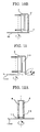
- FIG. 18A schematically shows a state in which a curtain liquid film does not deviate inward
- FIG. 18B schematically shows a state in which a curtain liquid film deviates inward.
- the present invention is designed in light of the above-mentioned problems in related art, and an object of the present invention is to provide a curtain coating apparatus, in which accumulation of a residue of liquid in a suction port and on a claw provided at a bottom of a curtain edge guide can be effectively prevented, and thus inward deviation of a curtain liquid film at the curtain edge guide can be reduced.
- a curtain coating apparatus has the features of claim 1.
- a curtain coating apparatus in which accumulation of a residue of liquid on a claw provided at a bottom of a curtain edge guide can be effectively prevented, and thus inward deviation of a curtain liquid film at the curtain edge guide can be reduced.
- the present invention provides a curtain coating apparatus , in which when a residue of liquid is left on a claw provided to support a curtain liquid film at a bottom of a curtain edge guide, the residue is removed.
- a unit (and a method) for moving the claw when a residue of liquid is left on the claw a unit (and a method) for pouring an auxiliary liquid onto a curtain liquid film contacting surface of the claw.
- the curtain coating apparatus (and the curtain coating method) of the present invention may employ both of these units (methods).
- the claw when a residue of liquid is left on a claw provided to support a curtain liquid film at a bottom of a curtain edge guide, the claw is moved so as to remove the residue from a curtain liquid film contacting surface of the claw and the vicinity thereof, and thus inward deviation of the curtain liquid film at the curtain edge guide, caused by accumulation of the residue on the curtain liquid film contacting surface and in a suction port, can be reduced; by cleaning off the residue remaining on the claw, which has been removed from the curtain liquid film contacting surface, it is always possible to prevent inward deviation of the curtain liquid film.
- a coating liquid is applied onto a continuously running web while pouring an auxiliary liquid from the surface provided in contact with the curtain liquid film in the curtain edge guide.
- the auxiliary liquid is not particularly limited as long as it is in liquid form and has fluidity.
- preferred examples of the auxiliary liquid include water, and solutions prepared by mixing water with resins or by mixing water with surfactants, etc.
- preferred examples of the auxiliary liquid include the solvent contained in the coating liquid, and solutions prepared by mixing the solvent with resins or by mixing the solvent with surfactants, etc.
- the shape of the claw may be arbitrarily decided as long as it is a disc-shaped claw which supports the curtain liquid film at the bottom of the curtain edge guide and receives the auxiliary liquid which has flowed down.
- the claw is in the form of a flat surface.
- the material for the claw may be arbitrarily selected unless it is corroded by the coating liquid and the auxiliary liquid.
- the material is selected from stainless steel, brass, aluminum, iron, glass, PET and so forth.
- a first embodiment not in accordance with the present invention is an embodiment in which curtain coating is performed using a claw in the form of a flat plate.
- a claw (claw configured to move back and forth) 101 placed at a bottom of a curtain edge guide 2 be moved back and forth (in the directions of the arrow B) a certain period of time after application of a coating liquid, or that the claw 101 be continuously moved back and forth from the beginning of the application of the coating liquid or a certain period of time after the application of the coating liquid, thereby preventing a residue of the liquid from accumulating on a curtain liquid film contacting surface of the claw.
- the curtain coating apparatus is provided with a function of moving the claw back and forth. Also, the residue is removed by suction using a residue-sucking vacuum unit (not shown) or the like.
- the rate at which the claw 101 moves back and forth is in the range of 0.00005 m/sec to 0.005 m/sec. If the rate is less than 0.00005 m/sec, a residue of the liquid accumulates on the curtain liquid film contacting surface of the claw, and thus the curtain liquid film deviates inward. If the rate is greater than 0.005 m/sec, the curtain liquid film cannot be supported by an edge of the claw, and thus the curtain liquid film deviates inward.
- a second embodiment which is in accordance with the present invention is an embodiment in which curtain coating is performed using a claw in the shape of a disc.
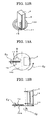
- FIG. 10A shows how a disc-shaped claw 102 rotates.
- FIG. 10B shows that the disc-shaped claw 102 is placed at a bottom of the curtain edge guide 2.
- An auxiliary liquid is poured from a surface provided in contact with a coating liquid in the curtain edge guide 2 and made to flow through a porous member 13.
- the claw 102 at the bottom of the curtain edge guide 2 be rotated a certain period of time after application of the coating liquid, or that the claw 102 be continuously rotated from the beginning of the application of the coating liquid or a certain period of time after the application of the coating liquid, thereby preventing a residue of the liquid from accumulating on a curtain liquid film contacting surface of the claw.
- the curtain coating apparatus is provided with a function of rotating the claw (which includes continuously rotating the claw). Also, the residue is removed by suction using a residue-sucking vacuum unit (not shown) or the like.
- the radius of the disc-shaped claw 102 be in the range of 10 mm to 50 mm. If the radius is less than 10 mm, the curvature of a portion of the claw to support the curtain liquid film is so great that the curtain liquid film swings when applied, and thus the coating width becomes unstable. If the radius is greater than 50 mm, the apparatus cannot be made compact.
- the rotational rate of the claw 102 as a circumferential speed is in the range of 0.0001 m/sec to 0.05 m/sec. If the rotational rate as a circumferential speed is less than 0.0001 m/sec, a residue of the liquid accumulates on the curtain liquid film contacting surface of the claw, and thus the curtain liquid film deviates inward. If the rotational rate as a circumferential speed is greater than 0.05 m/sec, the curtain liquid film cannot be supported by an edge of the claw, and thus the curtain liquid film deviates inward.
- a third embodiment which is not in accordance with the present invention is an embodiment in which curtain coating is performed using a claw in the form of a belt.
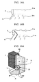
- FIG. 15A shows that a belt-like claw 103 is placed at a bottom of the curtain edge guide 2.
- FIG. 15B shows how the belt-like claw 103 moves in one direction (the direction of the arrow).
- the numeral 14 denotes driving rubber roll(s).
- the belt-like claw 103 is moved at least a certain period of time after application of a coating liquid so as to remove a residue of the liquid from a curtain liquid film contacting surface of the claw, and thus inward deviation of a curtain liquid film at the curtain edge guide 2, caused by accumulation of the residue on the curtain liquid film contacting surface, can be reduced. Also, it is possible to further reduce inward deviation of the curtain liquid film at the curtain edge guide 2 by applying the coating liquid while continuously moving the belt-like claw 103 at the bottom of the curtain edge guide 2, and thus always preventing a residue of the liquid from accumulating on the curtain liquid film contacting surface. Also, the residue is removed by suction using a residue-sucking vacuum unit (not shown) or the like. Accordingly, the curtain coating apparatus is provided with a function of moving the claw in the form of a belt (which includes continuously moving the claw).
- the rate at which the belt-like claw 103 moves is in the range of 0.00005 m/sec to 0.005 m/sec. If the rate is less than 0.00005 m/sec, a residue of the liquid accumulates on the curtain liquid film contacting surface of the claw, and thus the curtain liquid film deviates inward. If the rate is greater than 0.005 m/sec, the curtain liquid film cannot be supported by an edge of the claw, and thus the curtain liquid film deviates inward.
- a fourth embodiment which is not in accordance with the present invention is an embodiment in which curtain coating is performed using the claw (claw configured to move back and forth) 101 having an edge that slopes at an angle ⁇ , and, alternatively, in accordance with the invention the disc-shaped claw 102 having an edge (peripheral portion) that slopes at an angle ⁇ .
- FIG. 6 shows a state in which one edge of the claw 101 slopes upward at an angle ⁇ .
- FIG. 11 shows a state in which a peripheral portion of the claw 102 slopes upward at an angle ⁇ .
- the angle ⁇ is preferably in the range of 0° to 45°, more preferably in the range of 10° to 35°.
- the angle ⁇ is less than 0°, the edges of the curtain liquid films cannot be sufficiently supported by the respective claws, and thus the curtain liquid films deviate inward upon deposition of even small amounts of residues on the curtain liquid film contacting surfaces of the claws.
- a fifth embodiment of the present invention is an embodiment in which curtain coating is performed using the curtain edge guide 2 provided with a magnetic material 15; the claw not in accordance with the present invention (claw configured to move back and forth) 101, part or all of which is made of a magnetic material or a material attracted to the magnetic material 15 of the curtain edge guide 2; and the disc-shaped claw 102 in accordance with the present invention, part or all of which is made of a magnetic material or a material attracted to the magnetic material 15 of the curtain edge guide 2.
- FIGS. 7A and 7B each show that the employment of the above-mentioned structure makes it possible for the claw 101 to move back and forth in the directions of the arrow B.
- FIGS. 12A and 12B each show that the employment of the above-mentioned structure makes it possible for the claw 102 to rotate.
- the claw 101 can slide easily, so that a state in which there is no residue of liquid present on the curtain liquid film contacting surface of the claw can be easily achieved, and thus inward deviation of a curtain liquid film at the curtain edge guide 2 can be reduced.
- the disc-shaped claw 102 can rotate easily, so that a state in which there is no residue of liquid present on the curtain liquid film contacting surface of the claw can be easily achieved, and thus inward deviation of a curtain liquid film at the curtain edge guide 2 can be reduced.
- Preferred examples of the magnetic material include magnetite, KS steel, MK steel, ferrite magnets, samarium-cobalt magnets, alnico magnets, neodymium magnets, samarium-iron-nitrogen magnets, platinum magnets, praseodymium magnets, plastic magnets, manganese-aluminum magnets, iron-chromium-cobalt magnets, bond magnets and molecular magnets.
- Preferred examples of the material attracted to the magnetic material 15 include iron and stainless steel.
- a sixth embodiment of the present invention is an embodiment in which curtain coating is performed using a hydrophobic member to form a coating liquid (curtain liquid film) contacting surface of a claw.
- the use of the hydrophobic member to form the coating liquid (curtain liquid film) contacting surface of the claw makes it possible for the claw to repel water contained in a coating liquid and in an auxiliary liquid, and thus it is possible to reduce accumulation of a residue of the liquid on the curtain liquid film contacting surface of the claw and prevent inward deviation of a curtain liquid film.
- the hydrophobic member include resins such as Teflon (registered trademark), and silicon resins.
- a seventh embodiment of the present invention is an embodiment in which curtain coating is performed after or while cleaning off a residue of liquid accumulating on a claw.
- a brush, a scraper blade or the like is used to clean off the residue. Also, a residue-sucking vacuum unit configured to suck in the residue is provided in the vicinity of the brush, the scraper blade or the like.
- FIGS. 8A and 8B and FIGS. 9A and 9B each show that there is a device provided to clean off a residue of liquid left on the claw 101, while the curtain liquid film contacting surface of the claw 101 at the bottom of the curtain edge guide 2 is being continuously moved back and forth.
- FIGS. 8A and 8B are drawings showing an example in which brushes 16 are used to clean off a residue of liquid
- FIGS. 9A and 9B are drawings showing an example in which scraper blades 18 are used to clean off a residue of liquid.
- the numeral 17 denotes residue-sucking vacuum unit(s) configured to suck in the residue.
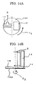
- FIGS. 13A and 13B and FIGS. 14A and 14B each show that there is a device provided to clean off a residue of liquid left on the disc-shaped claw 102, while the claw 102 is being continuously rotated, thereby making it possible at the time of continuous production to prevent accumulation of the residue on the liquid contacting surface of the claw and thus prevent inward deviation of a curtain liquid film.
- FIGS. 13A and 13B are drawings showing an example in which a brush 16 is used to clean off a residue of liquid
- FIGS. 14A and 14B are drawings showing an example in which a scraper blade 18 is used to clean off a residue of liquid.
- FIGS. 16A and 16B and FIGS. 17A and 17B each show that there is a device provided to clean off a residue of liquid left on the belt-like claw 103 which is not in accordance with the invention, while the claw 103 is being moved in one direction, thereby making it possible at the time of continuous production to prevent accumulation of the residue on the liquid contacting surface of the claw (the residue is sucked in the direction of the arrow D by a vacuum unit 17) and thus prevent inward deviation of a curtain liquid film.
- FIGS. 16A and 16B are drawings showing an example in which a brush 16 is used to clean off a residue of liquid
- FIGS. 17A and 17B are drawings showing an example in which a scraper blade 18 is used to clean off a residue of liquid.
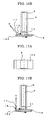
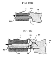
- FIGS. 19A and 19B A curtain coating method and a curtain coating apparatus of an eighth embodiment which is not in accordance with the invention are exemplarily represented by FIGS. 19A and 19B and are as follows: at least one layer of a coating liquid 12 is ejected from a slit, and the ejected coating liquid is made to fall freely by the curtain edge guide 2, which guides the coating liquid in the form of a curtain liquid film, so as to form a curtain liquid film 19 and apply the curtain liquid film 19 onto a continuously running web 5, while an auxiliary liquid is poured from the whole of a surface provided in contact with the coating liquid in the curtain edge guide, wherein an additional auxiliary liquid is made to flow as far as an edge of a claw surface where the curtain liquid film 19 (coating liquid 12) comes into contact with a claw 21 provided at a bottom of the curtain edge guide 2, so as to form a liquid film 202 of the additional auxiliary liquid between the claw 21 and the coating liquid 12 to be sucked into a suction port 22, and thus formation of a residue
- curtain edge guide auxiliary liquid The auxiliary liquid poured onto the surface provided in contact with the coating liquid in the curtain edge guide (hereinafter referred to as “curtain edge guide auxiliary liquid”) and the additional auxiliary liquid poured onto the claw's surface which is in contact with the coating liquid (hereinafter referred to as “claw liquid-contacting surface auxiliary liquid”) may be the same or different.
- the additional auxiliary liquid is not particularly limited as long as it is in liquid form and has fluidity.
- examples of the additional auxiliary liquid include water, and solutions prepared by mixing water with resins or by mixing water with surfactants, etc.
- examples of the auxiliary liquid include the solvent contained in the coating liquid, and solutions prepared by mixing the solvent with resins or by mixing the solvent with surfactants, etc. It should be noted that in the case where a solution containing a resin is used, the resin itself contained in the claw liquid-contacting surface auxiliary liquid may possibly be left as a residue, so that the claw liquid-contacting surface auxiliary liquid is preferably different from the curtain edge guide auxiliary liquid.
- the claw liquid-contacting surface auxiliary liquid is preferably water, or a solution prepared by mixing water with a surfactant, etc.
- the coating liquid is a solvent-like liquid
- the claw liquid-contacting surface auxiliary liquid is preferably the solvent contained in the coating liquid, or a solution prepared by mixing the solvent with a surfactant, etc.
- auxiliary liquid examples include water; alcohols such as methanol, ethanol, isopropanol, n-butanol and methylisocarbinol; ketones such as acetone, 2-butanone, ethyl amyl ketone, diacetone alcohol, isophorone and cyclohexanone; amides such as N,N-dimethylformamide and N,N-dimethylacetoamide; ethers such as diethyl ether, isopropyl ether, tetrahydrofuran, 1,4-dioxane and 3,4-dihydro-2H-pyran; glycol ethers such as 2-methoxyethanol, 2-ethoxyethanol, 2-butoxyethanol and ethyleneglycol dimethylether; glycol ether acetates such as 2-methoxyethyl acetate, 2-ethoxyethyl acetate and 2-butoxyethyl acetate; esters such as methyl acetate,
- the material for the claw 21 is not particularly limited unless it is corroded by the coating liquid and the auxiliary liquid, and the material may be arbitrarily selected. Examples thereof include stainless steel, brass, aluminum, iron, glass and PET.
- an edge of the claw 21 preferably slopes at an angle 25 ( ⁇ ).
- ⁇ an angle 25
- the edge of the claw slopes at an angle, it becomes easier for the curtain liquid film 19 to be in contact with the claw, and there is an increase in contact area between the claw and the curtain liquid film; therefore, the claw supports an edge of the curtain liquid film 19 to a greater extent, and thus it becomes possible to reduce inward deviation of the curtain liquid film.
- the angle 25 at which the edge of the claw 21 slopes is preferably in the range of 0° to 45°.
- the angle 25 is smaller than 0°, it is impossible to form a film of the auxiliary liquid between a member of the claw and the coating liquid to be sucked, and the edge of the curtain liquid film cannot be sufficiently supported by the claw, thus causing the curtain liquid film to deviate inward upon deposition of even a small amount of a residue of the liquid.
- the angle 25 is larger than 45°, the coating liquid easily moves to the back of the claw, so that the amount of the coating liquid attached becomes larger at edges of a coating film with respect to the coating width direction, and the coating film may not be sufficiently dried at the time of production.
- the coating liquid is possibly attached to a conveyance roll of a web, later smearing the coating film surface of the web, blocking possibly arises when a product is wound, and the web is possibly cut because of the swollen edges when the product is wound.
- the thickness 26 of the edge of the claw 21 is preferably 0.4 mm or less. When the thickness 26 is greater than 0.4 mm, it is impossible to form a film of the auxiliary liquid between the member of the claw and the coating liquid, and thus a residue of the liquid is attached to the liquid contacting surface at the edge of the claw, causing inward deviation of the curtain liquid film.
- Examples of units and methods for supplying the auxiliary liquid to the claw and pouring it onto the surface of the claw are as follows.
- auxiliary liquid (claw liquid-contacting surface auxiliary liquid 202) to flow on the claw's surface which is in contact with the coating liquid, and thus makes it possible to reduce formation of a residue of the liquid.
- a ninth embodiment which is not an embodiment of the present invention is an embodiment in which the claw 21, placed at the bottom of the curtain edge guide 2, has as its surface a superhydrophilic film 28 that exhibits superhydrophilicity, as shown in FIG. 24 .
- a liquid film is formed over the surface of the coating liquid to be sucked together with an auxiliary liquid, and this liquid film makes it possible to reduce formation of a residue of the liquid.
- Examples of methods for forming the superhydrophilic film include a method of coating the claw surface with a composition which contains a superhydrophilic material, and a method of affixing to the claw surface a film or sheet which contains a superhydrophilic material.
- Examples of the superhydrophilic material include photocatalysts.
- a photocatalyst is a material wherein when the material absorbs light having energy that exceeds the band gap energy, which is the energy difference between energy bands of a crystal of the material, i.e. between the upper limit of its valence band and the lower limit of its conduction band, photoexcitation occurs in which electrons in the valence band are excited into the conduction band, and these electrons and electron holes left due to the lack of electrons in the valence band induce photocatalytic reaction.
- Examples of the photocatalysts include titanium oxide, zinc oxide, tin oxide, ferric oxide and dibismuth trioxide. Among these, preference is given to titanium oxide because it improves in hydrophilicity with light absorption and is therefore superior in wettability.
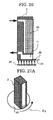
- a tenth embodiment which is not an embodiment of the present invention is an embodiment in which a light irradiation device 29 is provided so as to irradiate the surface of the claw 21 with excitation light, as shown in FIG. 25 .
- the excitation light is not particularly limited as long as it can excite the photocatalyst.
- an ultraviolet ray therefor.
- Examples of the light irradiation device configured to apply an ultraviolet ray include light irradiation units incorporating light sources such as germicidal lamps, black lights, xenon lamps, metal halide lamps and mercury vapor lamps. Irradiation with the excitation light makes it easily possible to sustain the excited state of the photocatalyst.
- An eleventh embodiment which is not an embodiment of the present invention is an embodiment in which an ultraviolet-transmitting member 31 is used to constitute the claw 21 placed at the bottom of the curtain edge guide 2, and the claw has the superhydrophilic film 28 as its surface, as shown in FIG. 26 .
- the use of the ultraviolet-transmitting member to constitute the claw makes it possible to continuously irradiate the superhydrophilic film, which contains a photocatalyst, with an ultraviolet ray from the back of the coating liquid contacting surface of the claw, and thus to sustain an excited state of the photocatalyst and thereby reduce formation of a residue of liquid even in long-time continuous coating.
- Examples of the ultraviolet-transmitting member include glass, acrylic resins and polyethylene films.
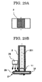
- a twelfth embodiment which is in accordance with the present invention is an embodiment in which the claw 21 placed at the bottom of the curtain edge guide 2 is in the shape of a disc and can rotate, the claw 21 has a photocatalyst-containing superhydrophilic film as its surface, and the light irradiation device 29 is provided, as shown in FIGS. 27(A) and 27(B) .
- the radius of the disc-shaped claw 21 is preferably in the range of 10 mm to 50 mm. If the radius is less than 10 mm, the curvature of a portion of the claw to support a curtain liquid film is great, causing the curtain liquid film to swing when applied, and thus the coating width becomes unstable. If the radius is greater than 50 mm, the apparatus cannot be made compact.
- the rotational rate of the claw 21 as a circumferential speed is preferably greater than 0 m/sec and less than or equal to 0.05 m/sec. If the rotational rate as a circumferential speed is 0 m/sec, the coating liquid contacting surface of the claw cannot be sufficiently irradiated with the ultraviolet ray, thereby shortening the length of time for which continuous coating is possible. If the rotational rate as a circumferential speed is greater than 0.05 m/sec, the curtain liquid film cannot be supported by an edge of the claw, and thus the curtain liquid film deviates inward.
- a thirteenth embodiment which is not in accordance with the present invention is an embodiment in which the claw 21 placed at the bottom of the curtain edge guide 2 can move back and forth, the claw 21 has a photocatalyst-containing superhydrophilic film as its surface, and the light irradiation device 29 is provided, as shown in FIGS. 28A and 28B .
- Driving rubber rolls 32 are provided over and under the claw 21.
- the rate at which the claw 21 moves back and forth is preferably greater than 0 m/sec and less than or equal to 0.005 m/sec. If the rate is 0 m/sec, the coating liquid contacting surface of the claw cannot be sufficiently irradiated with the ultraviolet ray, thereby shortening the length of time for which continuous coating is possible. If the rate is greater than 0.005 m/sec, a curtain liquid film cannot be supported by an edge of the claw, and thus the curtain liquid film deviates inward.
- a fourteenth embodiment which is not in accordance with the present invention is an embodiment in which the claw 21 placed at the bottom of a curtain edge guide 2 is in the form of a belt and can continuously move, the claw 21 has a photocatalyst-containing superhydrophilic film as its surface, and the light irradiation device 29 is provided, as shown in FIGS. 29A and 29B .
- Driving rubber rolls 32 are provided at both ends inside the belt-like claw 21.
- the rate at which the claw 21 moves is preferably greater than 0 m/sec and less than or equal to 0.005 m/sec. If the rate is 0 m/sec, the coating liquid contacting surface of the claw cannot be sufficiently irradiated with the ultraviolet ray, thereby shortening the length of time for which continuous coating is possible. If the rate is greater than 0.005 m/sec, a curtain liquid film cannot be supported by an edge of the claw, and thus the curtain liquid film deviates inward.
- Examples 1, 2 and 19 pertain to the above-mentioned second embodiment
- Example 3 pertains to the above-mentioned third embodiment
- Example 4 pertains to the above-mentioned third embodiment
- Examples 5 to 12 pertain to the above-mentioned fourth embodiment
- Examples 13 and 14 pertain to the above-mentioned fifth embodiment
- Examples 15 to 17 pertain to the above-mentioned sixth embodiment
- Examples 18 and 20 to 26 pertain to the above-mentioned seventh embodiment
- Examples 27 to 33 pertain to the above-mentioned eighth embodiment
- Example 34 pertains to the above-mentioned ninth embodiment
- Examples 35 pertains to the above-mentioned tenth embodiment
- Examples 36 and 37 pertain to the above-mentioned eleventh embodiment
- Examples 38 and 39 pertain to the above-mentioned twelfth embodiment
- Examples 40 and 41 pertain to the above-mentioned thirteenth embodiment
- Examples 42 and 43 pertain to the above-mentioned fourteenth embodiment.
- thermosensitive recording layer coating liquid prepared according to the following formulation was applied onto a web (paper) at a coating speed of 400 m/min, with a coating width of 250 mm and at a flow rate of coating liquid (ejected from a nozzle slit) of 3,000 g/min.
- the disc-shaped claw was made of stainless steel and was 20 mm in radius and 0.18 mm in thickness, the volume of an auxiliary liquid (water) flowing along the curtain edge guide was 30 cc/min, and the suction pressure of a vacuum unit for recovering the auxiliary liquid was -8 kpa. Also, the claw 102 was made to protrude from a curtain liquid film contacting surface of a porous member 13 (which was made of ceramic and was 50 ⁇ m in average pore diameter and 52% in porosity) by 2 mm. The results are shown in Table 1-A.
- thermosensitive recording layer coating liquid 150 mPa ⁇ s in viscosity, 38 mN/m in static surface tension
- the static surface tension was measured using the Automatic Surface Tensiometer CBVP-A3 (manufactured by Kyowa Interface Science Co., Ltd.).
- thermosensitive recording layer coating liquid was applied onto a web in the same manner as in Example 1, except that the radius of the disc-shaped claw 102 was changed from 20 mm to 5 mm.
- the results are shown in Table 1-A.
- thermosensitive recording layer coating liquid was applied onto a web in the same manner as in Example 1, except that the slide curtain coating apparatus shown in FIGS. 5A to 5C was used, in which a claw 101 (which was made of stainless steel and was 0.18 mm in thickness, 60 mm in length with respect to its moving direction and 30 mm in width) in the form of a flat plate was sandwiched between driving rubber rolls 14 and configured to move back and forth (at a rate of 0.005 m/sec).
- a claw 101 which was made of stainless steel and was 0.18 mm in thickness, 60 mm in length with respect to its moving direction and 30 mm in width
- the results are shown in Table 1-A.
- thermosensitive recording layer coating liquid was applied onto a web in the same manner as in Example 1, except that the slide curtain coating apparatus shown in FIGS. 15A to 15C was used, in which a belt-like claw 103 (which was made of stainless steel and was 0.01 mm in thickness, 80 mm in length with respect to its moving direction and 30 mm in width) was supported by driving rubber rolls 14 and was configured to move (at a rate of 0.005 m/sec).
- a belt-like claw 103 which was made of stainless steel and was 0.01 mm in thickness, 80 mm in length with respect to its moving direction and 30 mm in width
- driving rubber rolls 14 was configured to move (at a rate of 0.005 m/sec).
- thermosensitive recording layer coating liquid was applied onto a web in the same manner as in Example 1, except that a peripheral portion of the disc-shaped claw 102 sloped at an angle of 30° as shown in FIG. 11 .
- the results are shown in Table 1-A.
- thermosensitive recording layer coating liquid was applied onto a web in the same manner as in Example 1, except that the peripheral portion of the disc-shaped claw 102 sloped at an angle of 45° as shown in FIG. 11 .
- the results are shown in Table 1-A.
- thermosensitive recording layer coating liquid was applied onto a web in the same manner as in Example 1, except that the peripheral portion of the disc-shaped claw 102 sloped at an angle of 50° as shown in FIG. 11 .
- the results are shown in Table 1-A.
- thermosensitive recording layer coating liquid was applied onto a web in the same manner as in Example 1, except that the peripheral portion of the disc-shaped claw 102 sloped at an angle of 5° as shown in FIG. 11 .
- the results are shown in Table 1-A.
- thermosensitive recording layer coating liquid was applied onto a web in the same manner as in Example 3, except that one edge of the claw 101 in the form of a flat plate sloped at an angle of 30° as shown in FIG. 6 .
- the results are shown in Table 1-A.
- thermosensitive recording layer coating liquid was applied onto a web in the same manner as in Example 3, except that the one edge of the claw 101 in the form of a flat plate sloped at an angle of 45° as shown in FIG. 6 .
- the results are shown in Table 1-A.
- thermosensitive recording layer coating liquid was applied onto a web in the same manner as in Example 3, except that the one edge of the claw 101 in the form of a flat plate sloped at an angle of 50° as shown in FIG. 6 .
- the results are shown in Table 1-A.
- thermosensitive recording layer coating liquid was applied onto a web in the same manner as in Example 3, except that the one edge of the claw 101 in the form of a flat plate sloped at an angle of 5° as shown in FIG. 6 .
- the results are shown in Table 1-A.
- thermosensitive recording layer coating liquid was applied onto a web in the same manner as in Example 1, except that the slide curtain coating apparatus shown in FIGS. 12A and 12B was used, in which a magnetic member (magnet) 15 was attached to a curtain edge guide 2, the disc-shaped claw 102 (which was 20 mm in radius and 0.18 mm in thickness) was made of stainless steel (SUS 420) attracted to the magnetic member (magnet) 15, and the rotational rate of the claw as a circumferential speed was 0.01 m/sec.
- SUS 420 stainless steel
- thermosensitive recording layer coating liquid was applied onto a web in the same manner as in Example 1, except that the slide curtain coating apparatus shown in FIGS. 7A and 7B was used, in which a magnetic member (magnet) 15 was attached to a curtain edge guide 2, the claw 101 (which was 0.18 mm in thickness, 60 mm in length with respect to its moving direction and 30 mm in width) in the form of a flat plate was made of stainless steel (SUS 420) attracted to the magnetic member (magnet) 15, and the rate at which the claw moved back and forth was 0.005 m/sec.
- SUS 420 stainless steel
- thermosensitive recording layer coating liquid was applied onto a web in the same manner as in Example 1, except that a sheet of Teflon (registered trademark) having a thickness of 100 ⁇ m was affixed onto the coating liquid (curtain liquid film) contacting surface of the disc-shaped claw 102.
- Teflon registered trademark
- Table 1-A The results are shown in Table 1-A.
- thermosensitive recording layer coating liquid was applied onto a web in the same manner as in Example 3, except that a sheet of Teflon (registered trademark) having a thickness of 100 ⁇ m was affixed onto the coating liquid (curtain liquid film) contacting surface of the claw 101 which was in the form of a flat plate.
- Teflon registered trademark
- Table 1-B The results are shown in Table 1-B.
- thermosensitive recording layer coating liquid was applied onto a web in the same manner as in Example 4, except that a sheet of Teflon (registered trademark) having a thickness of 100 ⁇ m was affixed onto the coating liquid (curtain liquid film) contacting surface of the belt-like claw 103.
- Teflon registered trademark
- Table 1-B The results are shown in Table 1-B.
- thermosensitive recording layer coating liquid was applied onto a web in the same manner as in Example 1, except that the slide curtain coating apparatus shown in FIGS. 13A and 13B was used, in which the disc-shaped claw 102 was configured to rotate at a circumferential speed of 0.0001 m/sec by a drive motor, a circular brush 16 was installed on the opposite side to a curtain edge guide 2 and continuously rotated (at a circumferential speed of 0.05 m/sec) so as to oppose the rotational direction of the disc-shaped claw 102, and a residue of the liquid remaining on the disc-shaped claw was sucked (under a suction pressure of -0.01 MPa) by a residue-sucking vacuum unit 17.
- Table 1-B The results are shown in Table 1-B.
- thermosensitive recording layer coating liquid was applied onto a web in the same manner as in Example 18, except that the circumferential speed of the disc-shaped claw 102 was changed to 0.1 m/sec. The results are shown in Table 1-B.
- the slide curtain coating apparatus shown in FIGS. 14A to 14C was used, in which the disc-shaped claw 102, the same one as in Example 1, was configured to rotate at a circumferential speed of 0.0001 m/sec by a drive motor, a scraper blade 18 (which was made of polyethylene and was 0.4 mm in thickness) was installed in a slanting manner on the opposite side to a curtain edge guide 2 so as to oppose the rotational direction of the disc-shaped claw 102, and a residue of liquid remaining on the disc-shaped claw was sucked (under a suction pressure of -0.01 MPa) by a residue-sucking vacuum unit 17.
- Table 1-B The results are shown in Table 1-B.
- the slide curtain coating apparatus shown in FIGS. 8A and 8B was used, in which the length (with respect to its moving direction) of the claw 101 in the form of a flat plate, the same one as in Example 3, was increased to 100 mm, the claw 101 was sandwiched between driving rubber rolls 14, the driving rubber rolls 14 were rotated by a drive motor so as to move the claw 101 back and forth in a controlled manner at a rate of 0.0005 m/sec, circular brushes 16 were continuously rotated (at a circumferential speed of 0.05 m/sec) between a curtain edge guide 2 and the driving rubber rolls 14 so as to oppose the moving direction of the claw, and a residue of liquid remaining on the claw was sucked (under a suction pressure of -0.01 MPa) by residue-sucking vacuum units 17.
- Table 1-B The results are shown in Table 1-B.
- thermosensitive recording layer coating liquid was applied onto a web in the same manner as in Example 21, except that the claw 101 was configured to move back and forth in a controlled manner at a rate of 0.01 m/sec.
- the results are shown in Table 1-B.
- the slide curtain coating apparatus shown in FIGS. 9A and 9B was used, in which the length (with respect to its moving direction) of the claw 101 in the form of a flat plate, the same one as in Example 3, was increased to 100 mm, the claw 101 was sandwiched between driving rubber rolls 14, the driving rubber rolls 14 were rotated by a drive motor so as to move the claw 101 back and forth in a controlled manner at a rate of 0.00005 m/sec, scraper blades 18 (which were made of polyethylene and were 0.4 mm in thickness each) were installed in a slanting manner between a curtain edge guide and the driving rubber rolls so as to oppose the moving direction of the claw, and a residue of liquid remaining on the claw was sucked (under a suction pressure of -0.01 MPa) by residue-sucking vacuum units 17.
- Table 1-B The results are shown in Table 1-B.
- the slide curtain coating apparatus shown in FIGS. 16A and 16B was used, in which the belt-like claw 103, the same one as in Example 4, was supported by driving rubber rolls 14, the driving rubber rolls 14 were rotated by a drive motor so as to move the claw 103 in one direction at a rate of 0.00005 m/sec, a circular brush 16 was continuously rotated (at a circumferential speed of 0.05 m/sec) so as to oppose the moving direction of the claw 103, and a residue of liquid remaining on the claw was sucked (under a suction pressure of -0.01 MPa) by a residue-sucking vacuum unit 17.
- Table 1-B The results are shown in Table 1-B.
- thermosensitive recording layer coating liquid was applied onto a web in the same manner as in Example 24, except that the rate at which the claw 103 moved was changed to 0.01 m/sec. The results are shown in Table 1-B.
- the slide curtain coating apparatus shown in FIGS. 17A and 17B was used, in which the belt-like claw 103, the same one as in Example 4, was supported by driving rubber rolls 14, the driving rubber rolls 14 were rotated by a drive motor so as to move the claw 103 in one direction at a rate of 0.00005 m/sec, a scraper blade 18 (which was made of polyethylene and was 0.4 mm in thickness) was installed in a slanting manner so as to oppose the moving direction of a residue of liquid on the claw, and the residue was sucked (under a suction pressure of -0.01 MPa) by a vacuum unit 17.
- Table 1-B The results are shown in Table 1-B.
- Example 1 As shown in FIG. 2 , a bottom of a curtain edge guide of a slide curtain coating apparatus was fixed, and coating was carried out as in Example 1. The results are shown in Table 1-B.
- An apparatus was used that included the slide curtain coating apparatus shown in FIG. 2 , the claw 21 shown in FIGS. 19A and 19B provided at a bottom of the curtain edge guide of the slide curtain coating apparatus, and the two pouring pipes 27 shown in FIG. 21 , in which it was possible to make an auxiliary liquid flow as far as an edge of the claw. Water was used as the auxiliary liquid.
- thermosensitive recording layer coating liquid prepared according to the following formulation was applied onto a web (paper) at a coating speed of 400 m/min, with a coating width of 250 mm and at a flow rate of coating liquid (ejected from a nozzle slit) of 3,000 g/min.
- the volume of the auxiliary liquid (water) on the liquid contacting surface of the claw was 120 cc/min (60 cc/min each)
- the volume of an auxiliary liquid (water) flowing along the curtain edge guide was 30 cc/min
- the suction pressure of a vacuum unit for recovering the auxiliary liquid was -20 kpa.
- the claw was made to protrude from a curtain liquid film contacting surface of a porous member by 2 mm.
- the thickness of the edge of the claw, denoted by the numeral 26 in FIG. 20 was 0.1 mm
- the angle ⁇ at which the edge of the claw sloped denoted by the numeral 25 in FIG. 20 , was 30°.
- Table 2 The results are shown in Table 2.
- thermosensitive recording layer coating liquid 150 mPa.s in viscosity, 38 mN/m in static surface tension
- the static surface tension was measured using the Automatic Surface Tensiometer CBVP-A3 (manufactured by Kyowa Interface Science Co., Ltd.).
- thermosensitive recording layer coating liquid was applied onto a web in the same manner as in Example 27, except that the angle at which the edge of the claw 21 sloped was changed to 0°. The results are shown in Table 2.
- thermosensitive recording layer coating liquid was applied onto a web in the same manner as in Example 27, except that the angle at which the edge of the claw 21 sloped was changed to 45°. The results are shown in Table 2.
- thermosensitive recording layer coating liquid was applied onto a web in the same manner as in Example 27, except that the angle at which the edge of the claw 21 sloped was changed to 50°. The results are shown in Table 2.
- thermosensitive recording layer coating liquid was applied onto a web in the same manner as in Example 27, except that the angle at which the edge of the claw 21 sloped was changed to -5°. The results are shown in Table 2.
- thermosensitive recording layer coating liquid was applied onto a web in the same manner as in Example 27, except that the thickness of the edge of the claw 21 was changed to 0.4 mm. The results are shown in Table 2.
- thermosensitive recording layer coating liquid was applied onto a web in the same manner as in Example 27, except that the thickness of the edge of the claw 21 was changed to 0.5 mm. The results are shown in Table 2.
- thermosensitive recording layer coating liquid was applied onto a web in the same manner as in Example 27, except that the auxiliary liquid (water) was poured such that the volume of the auxiliary liquid (water) on the liquid contacting surface of the claw 21 (the volume of the claw liquid-contacting surface auxiliary liquid 202) was 100 cc/min, as shown in FIG. 22 .
- the results are shown in Table 2.
- thermosensitive recording layer coating liquid was applied onto a web in the same manner as in Example 27, except that a claw surface 24 was formed of stainless steel mesh, and the auxiliary liquid (water) was poured such that the volume of the auxiliary liquid (water) streaming onto the liquid contacting surface of the claw 21 (the volume of the claw liquid-contacting surface auxiliary liquid 202) was 100 cc/min, as shown in FIG. 23 .
- Table 2 The results are shown in Table 2.
- thermosensitive recording layer coating liquid was applied onto a web in the same manner as in Example 27, except that the claw surface 24 was formed of a porous member, and the auxiliary liquid (water) was poured such that the volume of the auxiliary liquid (water) streaming onto the liquid contacting surface of the claw 21 (the volume of the claw liquid-contacting surface auxiliary liquid 202) was 100 cc/min, as shown in FIG. 23 .
- Table 2 The results are shown in Table 2.
- thermosensitive recording layer coating liquid was applied onto a web in the same manner as in Example 27, except that a photocatalyst sheet (HYDROTECTFILM, produced by TOTO LTD.) was affixed as a superhydrophilic film 28 to the surface (coating liquid contacting surface) of the claw 21, as shown in FIG. 24 .
- HYDROTECTFILM produced by TOTO LTD.
- thermosensitive recording layer coating liquid was applied onto a web in the same manner as in Example 34, except that the surface (coating liquid contacting surface) of the claw 21 was irradiated with an ultraviolet ray using a black light as a light irradiation device 29, as shown in FIG. 25 .
- the results are shown in Table 2.
- thermosensitive recording layer coating liquid was applied onto a web in the same manner as in Example 27, except that the claw 21, formed by affixing a photocatalyst sheet (HYDROTECTFILM, produced by TOTO LTD.) as a superhydrophilic film 28 to a surface of a PET film (0.2 mm in thickness) as an ultraviolet-transmitting member 31, was irradiated with an ultraviolet ray from the surface opposite to the coating liquid contacting surface, using an ultraviolet lamp (TBB-30, manufactured by HYBEC CORPORARION) having a tube diameter of 3 mm and a length of 30 mm and serving as a light irradiation device 29, as shown in FIG. 26 .
- TB-30 manufactured by HYBEC CORPORARION
- thermosensitive recording layer coating liquid was applied onto a web in the same manner as in Example 36, except that the claw was not irradiated with an ultraviolet ray.
- the results are shown in Table 2.
- thermosensitive recording layer coating liquid was applied onto a web in the same manner as in Example 27, except that the claw 21 was a disc-shaped claw (which was made of stainless steel and was 20 mm in radius and 0.18 mm in thickness), a photocatalyst sheet (HYDROTECTFILM, produced by TOTO LTD.) was affixed as a superhydrophilic film 28 to the coating liquid contacting surface of the claw 21, the claw 21 was rotated at a circumferential speed of 0.0001 m/sec by a drive motor, and the surface of the claw 21 was irradiated with an ultraviolet ray using a black light as a light irradiation device 29, as shown in FIGS. 27A and 27B .
- Table 2 The results are shown in Table 2.
- thermosensitive recording layer coating liquid was applied onto a web in the same manner as in Example 38, except that the disc-shaped claw 21 was not rotated. The results are shown in Table 2.
- thermosensitive recording layer coating liquid was applied onto a web in the same manner as in Example 38, except that the circumferential speed of the claw 21 was changed to 0.1 m/sec. The results are shown in Table 2.
- thermosensitive recording layer coating liquid was applied onto a web in the same manner as in Example 27, except that the length of the claw 21 with respect to its moving direction was changed to 1,000 mm, the width of the claw 21 was changed to 30 mm, a photocatalyst sheet (HYDROTECTFILM, produced by TOTO LTD.) was affixed as a superhydrophilic film 28 to the coating liquid contacting surface of the claw, the claw with the superhydrophilic film was sandwiched between driving rubber rolls 32 and configured to move back and forth in a controlled manner at a rate of 0.00005 m/sec by a motor, and the superhydrophilic film 28 was irradiated with an ultraviolet ray using a black light as a light irradiation device 29, as shown in FIGS. 28A and 28B .
- Table 2 The results are shown in Table 2.
- thermosensitive recording layer coating liquid was applied onto a web in the same manner as in Example 40, except that the claw 21 was not configured to move back and forth. The results are shown in Table 2.
- thermosensitive recording layer coating liquid was applied onto a web in the same manner as in Example 40, except that the rate at which the claw 21 moved back and forth was changed to 0.01 m/sec. The results are shown in Table 2.
- thermosensitive recording layer coating liquid was applied onto a web in the same manner as in Example 27, except that the claw 21 was made of stainless steel and was in the form of a belt (which was 800 mm in length with respect to its moving direction, 30 mm in width and 0.01 mm in thickness), a photocatalyst sheet (HYDROTECTFILM, produced by TOTO LTD.) was affixed as a superhydrophilic film 28 to the coating liquid contacting surface of the claw, the claw with the superhydrophilic film was supported by driving rubber rolls 32 and configured to move at a rate of 0.00005 m/sec by the use of a drive motor, and the superhydrophilic film 28 was irradiated with an ultraviolet ray using a black light as a light irradiation device 29, as shown in FIGS. 29A and 29B .
- Table 2 The results are shown in Table 2.
- thermosensitive recording layer coating liquid was applied onto a web in the same manner as in Example 42, except that the claw 21 was not moved. The results are shown in Table 2.
- thermosensitive recording layer coating liquid was applied onto a web in the same manner as in Example 42, except that the rate at which the claw 21 moved was changed to 0.01 m/sec. The results are shown in Table 2.
- thermosensitive recording layer coating liquid was applied onto a web in the same manner as in Example 27, except that an auxiliary liquid was not poured onto the coating liquid contacting surface of the claw 21.
- Table 2 Results Residue on coating liquid contacting surface of claw Inward deviation of curtain liquid film Ex. 28 The presence of a residue could be constantly prevented. The curtain liquid film did not deviate inward. Ex. 29 The presence of a residue could be constantly prevented. The curtain liquid film did not deviate inward. Ex. 30 The presence of a residue could be constantly prevented. The curtain liquid film did not deviate inward. Ref. Ex. 1 A residue was attached to the back of the claw The curtain liquid film deviated inward 1 hr after the start. Ref. Ex.
- the curtain liquid film deviated inward 18 hr after the start. Ex. 35 The presence of a residue could be constantly prevented.
- Ex. 36 The presence of a residue could be constantly prevented.
- Ex. 37 No residue was present until 16 hr after the start, then a residue started to exist.
- Ex. 38 The presence of a residue could be constantly prevented.
- Ex. 39 No residue was present until 16 hr after the start, then a residue started to exist.
- the curtain liquid film deviated inward 18 hr after the start Ref. Ex.4 The curtain liquid film was difficult to support.
Landscapes
- Coating Apparatus (AREA)
- Application Of Or Painting With Fluid Materials (AREA)
Claims (10)
- Vorhangbeschichtungsvorrichtung umfassend:einen Schlitz (1), aus welchem mindestens eine Schicht einer Beschichtungsflüssigkeit ausgestoßen werden kann,eine Vorhang-Kantenführung (2), die konfiguriert ist, die ausgestoßene Beschichtungsflüssigkeit in der Form eines Vorhangflüssigkeitsfilms (3) zu führen und die Beschichtungsflüssigkeit frei fallen zu lassen, während eine Hilfsflüssigkeit (9) von der Gesamtheit einer in der Vorhang-Kantenführung in Kontakt mit der Beschichtungsflüssigkeit bereitgestellten Oberfläche ausgegossen wird, sodass die Beschichtungsflüssigkeit auf eine kontinuierlich laufende Bahn (5) aufgebracht wird, undeine Klaue (102), welche den Vorhangflüssigkeitsfilm an einer Unterseite der Vorhang-Kantenführung abstützt,dadurch gekennzeichnet, dass die Klaue eine scheibenförmige Klaue ist und konfiguriert ist sich zu drehen.
- Vorhangbeschichtungsvorrichtung gemäß Anspruch 1, wobei die Vorhangvorrichtung ferner einen Antriebsmotor umfasst, der konfiguriert ist, die scheibenförmige Klaue in Drehung zu versetzen.
- Vorhangbeschichtungsvorrichtung gemäß einem der Ansprüche 1 und 2, wobei eine Kante der Klaue (102) mit einem Winkel abgeschrägt ist.
- Vorhangbeschichtungsvorrichtung gemäß Anspruch 3, wobei der Winkel in dem Bereich von 0° bis 45° ist.
- Vorhangbeschichtungsvorrichtung gemäß irgendeinem der Ansprüche 1 bis 4, wobei die Vorhang-Kantenführung (2) mit einem magnetischen Material (15) versehen ist, und ein Teil der Klaue oder die gesamte Klaue aus einem magnetischen Material oder einem Material angezogen zu dem magnetischen Material der Vorhang-Kantenführung hergestellt ist.
- Vorhangbeschichtungsvorrichtung gemäß irgendeinem der Ansprüche 1 bis 5, wobei die Klaue eine aus einem hydrophilen Element gebildete Beschichtungsflüssigkeits-Kontaktoberfläche aufweist.
- Vorhangbeschichtungsvorrichtung gemäß irgendeinem der Ansprüche 1 bis 6, ferner umfassend eine Einheit (16, 18), die konfiguriert ist, einen Rückstand der sich auf der Klaue ansammelnden Flüssigkeit wegzureinigen.
- Vorhangbeschichtungsvorrichtung gemäß irgendeinem der Ansprüche 2 bis 7, wobei die Klaue konfiguriert ist, sich mindestens einen gewissen Zeitraum lang zu drehen, nachdem die Beschichtungsflüssigkeit auf die Bahn aufgebracht wurde.
- Vorhangbeschichtungsvorrichtung gemäß irgendeinem der Ansprüche 2 bis 7, wobei die Beschichtungsflüssigkeit auf die Bahn aufgebracht werden kann, während die Klaue fortlaufend gedreht oder bewegt wird.
- Vorhangbeschichtungsvorrichtung gemäß irgendeinem der Ansprüche 1 bis 9, wobei die den Vorhangflüssigkeitsfilm kontaktierende Oberfläche der Klaue aus einem superhydrophilen Film gebildet wird, welcher ein superhydrophiles Material enthält.
Applications Claiming Priority (2)
| Application Number | Priority Date | Filing Date | Title |
|---|---|---|---|
| JP2008188154A JP5169571B2 (ja) | 2008-07-22 | 2008-07-22 | カーテン塗布方法及び装置 |
| JP2009120552A JP5439945B2 (ja) | 2009-05-19 | 2009-05-19 | カーテン塗布方法及び装置 |
Publications (2)
| Publication Number | Publication Date |
|---|---|
| EP2147724A1 EP2147724A1 (de) | 2010-01-27 |
| EP2147724B1 true EP2147724B1 (de) | 2012-06-20 |
Family
ID=40909898
Family Applications (1)
| Application Number | Title | Priority Date | Filing Date |
|---|---|---|---|
| EP09166036A Not-in-force EP2147724B1 (de) | 2008-07-22 | 2009-07-21 | Vorhangbeschichtungsvorrichtung |
Country Status (3)
| Country | Link |
|---|---|
| US (1) | US8522713B2 (de) |
| EP (1) | EP2147724B1 (de) |
| CN (1) | CN103182356B (de) |
Families Citing this family (5)
| Publication number | Priority date | Publication date | Assignee | Title |
|---|---|---|---|---|
| DE102010029397A1 (de) * | 2010-05-27 | 2011-12-01 | Fmp Technology Gmbh Fluid Measurements & Projects | Verfahren und Vorrichtung zur Beschichtung eines Substrats |
| BR112012032776A2 (pt) | 2010-08-04 | 2018-02-27 | Ricoh Co Ltd | método de revestimento de rolo de lâmina e aparelho de revestimento derolo de lâmina |
| CN102553778B (zh) | 2010-10-05 | 2014-10-01 | 株式会社理光 | 幕涂方法和幕涂设备 |
| JP5938980B2 (ja) | 2011-03-31 | 2016-06-22 | 株式会社リコー | カーテン塗布方法及びカーテン塗布装置 |
| US9333524B2 (en) | 2013-03-15 | 2016-05-10 | Ricoh Company, Ltd. | Slot curtain coating apparatus and slot curtain coating method |
Family Cites Families (22)
| Publication number | Priority date | Publication date | Assignee | Title |
|---|---|---|---|---|
| DE3300150A1 (de) | 1983-01-04 | 1984-07-05 | Agfa-Gevaert Ag, 5090 Leverkusen | Verfahren und vorrichtung zur stabilisierung von frei fallenden fluessigkeitsvorhaengen |
| DE3468544D1 (en) | 1984-10-05 | 1988-02-11 | Agfa Gevaert Nv | Method and apparatus for curtain coating |
| WO1990000939A1 (en) | 1988-07-20 | 1990-02-08 | Eastman Kodak Company | Curtain coating edge control method and apparatus |
| EP0520091B1 (de) | 1991-06-18 | 1995-12-13 | Agfa-Gevaert N.V. | Vorhangbeschichter |
| US5763013A (en) * | 1997-02-05 | 1998-06-09 | Eastman Kodak Company | Edge removal apparatus including air-flow blocking means for curtain coating |
| DE19735588A1 (de) | 1997-04-21 | 1999-02-18 | Jagenberg Papiertech Gmbh | Verfahren und Vorrichtung zum Auftragen einer Pigmentstreichfarbe auf eine Papier- oder Kartonbahn |
| DE59807083D1 (de) * | 1997-08-15 | 2003-03-06 | Voith Paper Patent Gmbh | Verfahren und vorrichtung zum auftragen einer pigmentstreichfarbe auf eine papier- oder kartonbahn |
| EP0907103B1 (de) | 1997-10-03 | 2000-08-09 | Troller Schweizer Engineering AG | Verfahren und Apparatur zur Vorhangbeschichtung eines bewegten Trägers |
| JP3726496B2 (ja) | 1998-06-15 | 2005-12-14 | コニカミノルタホールディングス株式会社 | カーテン塗布補助液体供給方法 |
| DE19903260A1 (de) | 1999-01-28 | 2000-08-03 | Agfa Gevaert Ag | Verfahren und Vorrichtung zum Vorhangbeschichten |
| JP2001046939A (ja) | 1999-08-11 | 2001-02-20 | Mitsubishi Paper Mills Ltd | 塗布装置および塗布方法 |
| JP2001104856A (ja) | 1999-10-06 | 2001-04-17 | Fuji Photo Film Co Ltd | カーテン塗布方法及びカーテン塗布装置 |
| DE19962844A1 (de) | 1999-12-23 | 2001-07-05 | Bachofen & Meier Ag Maschf | Verfahren und Vorrichtung zum Beschichten einer laufenden Materialbahn |
| EP1458492B1 (de) | 2001-12-13 | 2010-05-05 | Dow Global Technologies Inc. | Verfahren und vorrichtung zur vorhangbeschichtung |
| DE102004016923B4 (de) | 2004-04-06 | 2006-08-03 | Polytype Converting S.A. | Vorhangbeschichter und Vorhangbeschichtungsverfahren |
| DE102005062080A1 (de) | 2005-12-22 | 2007-06-28 | Voith Patent Gmbh | Verfahren und Vorrichtung zum Auftragen eines Auftragsmediums auf eine Materialbahn |
| DE102006019788A1 (de) | 2006-04-28 | 2007-10-31 | Voith Patent Gmbh | Vorhang-Auftragswerk |
| JP5380807B2 (ja) | 2006-09-15 | 2014-01-08 | 株式会社リコー | スライドカーテン塗布装置及びスライドカーテン塗布方法 |
| US7870833B2 (en) | 2006-09-15 | 2011-01-18 | Ricoh Company, Ltd. | Slide curtain coating apparatus and slide curtain coating method |
| JP5481788B2 (ja) | 2007-02-27 | 2014-04-23 | 株式会社リコー | 感熱塗膜材料およびその製造方法 |
| JP4846629B2 (ja) | 2007-03-12 | 2011-12-28 | 株式会社リコー | カーテン塗布装置及びカーテン塗布方法 |
| FI121189B (fi) | 2007-10-17 | 2010-08-13 | Metso Paper Inc | Reunaohjain ja menetelmä verhopäällystyksessä muodostettavan reunaohjaimen toiminta-ajan pidentämiseksi |
-
2009
- 2009-07-21 EP EP09166036A patent/EP2147724B1/de not_active Not-in-force
- 2009-07-21 US US12/506,452 patent/US8522713B2/en active Active
- 2009-07-22 CN CN201310054897.1A patent/CN103182356B/zh not_active Expired - Fee Related
Also Published As
| Publication number | Publication date |
|---|---|
| US8522713B2 (en) | 2013-09-03 |
| EP2147724A1 (de) | 2010-01-27 |
| CN103182356B (zh) | 2015-10-21 |
| CN103182356A (zh) | 2013-07-03 |
| US20100021645A1 (en) | 2010-01-28 |
Similar Documents
| Publication | Publication Date | Title |
|---|---|---|
| EP2147724B1 (de) | Vorhangbeschichtungsvorrichtung | |
| JPH0247272B2 (de) | ||
| JP4037911B2 (ja) | ダイエッジ洗浄システム | |
| CN101632973B (zh) | 帘式涂布装置 | |
| JP2001508700A (ja) | スライドコータの表面上における塗液の乾燥を最小限にする装置および方法 | |
| WO1990000939A1 (en) | Curtain coating edge control method and apparatus | |
| JP5972932B2 (ja) | 塗布装置及び塗布方法 | |
| JP5439945B2 (ja) | カーテン塗布方法及び装置 | |
| JP3634579B2 (ja) | 塗布装置及び塗布方法 | |
| JP5416617B2 (ja) | 塗布システム、及び塗布方法 | |
| JP2010214252A (ja) | バー塗布装置、及びバー塗布方法 | |
| JP2001170542A (ja) | 塗布装置 | |
| CN112770846B (zh) | 薄膜制造方法及薄膜卷 | |
| WO1993014878A1 (en) | Method of and device for application | |
| JP2004105960A (ja) | 移動するシート状物のカーテンコーティング方法及び装置 | |
| JPH07185432A (ja) | 塗装ホッパーを調製する装置 | |
| JP4979523B2 (ja) | バー塗布装置、バー塗布装置を用いた塗布方法、及び光学フィルムの製造方法 | |
| JP2007330873A (ja) | 塗布装置および塗布方法 | |
| JP2006326421A (ja) | 塗布装置および塗布方法 | |
| JP2008018386A (ja) | カーテン塗布装置及びカーテン塗布方法 | |
| JPH11104547A (ja) | ウェブ塗布面のストリーク防止方法 | |
| JP5356125B2 (ja) | バー塗布装置及びバー塗布方法 | |
| JP2012035228A (ja) | カーテン塗工装置 | |
| JPH07108213A (ja) | 塗布方法 | |
| JPH047055A (ja) | 塗布装置及び塗布方法 |
Legal Events
| Date | Code | Title | Description |
|---|---|---|---|
| PUAI | Public reference made under article 153(3) epc to a published international application that has entered the european phase |
Free format text: ORIGINAL CODE: 0009012 |
|
| AK | Designated contracting states |
Kind code of ref document: A1 Designated state(s): AT BE BG CH CY CZ DE DK EE ES FI FR GB GR HR HU IE IS IT LI LT LU LV MC MK MT NL NO PL PT RO SE SI SK SM TR |
|
| AX | Request for extension of the european patent |
Extension state: AL BA RS |
|
| 17P | Request for examination filed |
Effective date: 20100428 |
|
| 17Q | First examination report despatched |
Effective date: 20100527 |
|
| GRAP | Despatch of communication of intention to grant a patent |
Free format text: ORIGINAL CODE: EPIDOSNIGR1 |
|
| RTI1 | Title (correction) |
Free format text: CURTAIN COATING APPARATUS |
|
| RIN1 | Information on inventor provided before grant (corrected) |
Inventor name: HARA, TETSUYA Inventor name: KOBORI, HIDEYUKI Inventor name: HANAI, SHUJI Inventor name: NAGASAWA, NOBUYUKI Inventor name: SHIMIZU, TOMOHITO |
|
| GRAS | Grant fee paid |
Free format text: ORIGINAL CODE: EPIDOSNIGR3 |
|
| GRAA | (expected) grant |
Free format text: ORIGINAL CODE: 0009210 |
|
| AK | Designated contracting states |
Kind code of ref document: B1 Designated state(s): AT BE BG CH CY CZ DE DK EE ES FI FR GB GR HR HU IE IS IT LI LT LU LV MC MK MT NL NO PL PT RO SE SI SK SM TR |
|
| REG | Reference to a national code |
Ref country code: GB Ref legal event code: FG4D |
|
| REG | Reference to a national code |
Ref country code: CH Ref legal event code: EP |
|
| REG | Reference to a national code |
Ref country code: AT Ref legal event code: REF Ref document number: 562718 Country of ref document: AT Kind code of ref document: T Effective date: 20120715 |
|
| REG | Reference to a national code |
Ref country code: IE Ref legal event code: FG4D |
|
| REG | Reference to a national code |
Ref country code: DE Ref legal event code: R096 Ref document number: 602009007644 Country of ref document: DE Effective date: 20120816 |
|
| PG25 | Lapsed in a contracting state [announced via postgrant information from national office to epo] |
Ref country code: FI Free format text: LAPSE BECAUSE OF FAILURE TO SUBMIT A TRANSLATION OF THE DESCRIPTION OR TO PAY THE FEE WITHIN THE PRESCRIBED TIME-LIMIT Effective date: 20120620 Ref country code: NO Free format text: LAPSE BECAUSE OF FAILURE TO SUBMIT A TRANSLATION OF THE DESCRIPTION OR TO PAY THE FEE WITHIN THE PRESCRIBED TIME-LIMIT Effective date: 20120920 Ref country code: LT Free format text: LAPSE BECAUSE OF FAILURE TO SUBMIT A TRANSLATION OF THE DESCRIPTION OR TO PAY THE FEE WITHIN THE PRESCRIBED TIME-LIMIT Effective date: 20120620 Ref country code: SE Free format text: LAPSE BECAUSE OF FAILURE TO SUBMIT A TRANSLATION OF THE DESCRIPTION OR TO PAY THE FEE WITHIN THE PRESCRIBED TIME-LIMIT Effective date: 20120620 |
|
| REG | Reference to a national code |
Ref country code: NL Ref legal event code: VDEP Effective date: 20120620 |
|
| REG | Reference to a national code |
Ref country code: AT Ref legal event code: MK05 Ref document number: 562718 Country of ref document: AT Kind code of ref document: T Effective date: 20120620 |
|
| REG | Reference to a national code |
Ref country code: LT Ref legal event code: MG4D Effective date: 20120620 |
|
| PG25 | Lapsed in a contracting state [announced via postgrant information from national office to epo] |
Ref country code: SI Free format text: LAPSE BECAUSE OF FAILURE TO SUBMIT A TRANSLATION OF THE DESCRIPTION OR TO PAY THE FEE WITHIN THE PRESCRIBED TIME-LIMIT Effective date: 20120620 Ref country code: HR Free format text: LAPSE BECAUSE OF FAILURE TO SUBMIT A TRANSLATION OF THE DESCRIPTION OR TO PAY THE FEE WITHIN THE PRESCRIBED TIME-LIMIT Effective date: 20120620 Ref country code: GR Free format text: LAPSE BECAUSE OF FAILURE TO SUBMIT A TRANSLATION OF THE DESCRIPTION OR TO PAY THE FEE WITHIN THE PRESCRIBED TIME-LIMIT Effective date: 20120921 Ref country code: LV Free format text: LAPSE BECAUSE OF FAILURE TO SUBMIT A TRANSLATION OF THE DESCRIPTION OR TO PAY THE FEE WITHIN THE PRESCRIBED TIME-LIMIT Effective date: 20120620 |
|
| PG25 | Lapsed in a contracting state [announced via postgrant information from national office to epo] |
Ref country code: IS Free format text: LAPSE BECAUSE OF FAILURE TO SUBMIT A TRANSLATION OF THE DESCRIPTION OR TO PAY THE FEE WITHIN THE PRESCRIBED TIME-LIMIT Effective date: 20121020 Ref country code: SK Free format text: LAPSE BECAUSE OF FAILURE TO SUBMIT A TRANSLATION OF THE DESCRIPTION OR TO PAY THE FEE WITHIN THE PRESCRIBED TIME-LIMIT Effective date: 20120620 Ref country code: BE Free format text: LAPSE BECAUSE OF FAILURE TO SUBMIT A TRANSLATION OF THE DESCRIPTION OR TO PAY THE FEE WITHIN THE PRESCRIBED TIME-LIMIT Effective date: 20120620 Ref country code: EE Free format text: LAPSE BECAUSE OF FAILURE TO SUBMIT A TRANSLATION OF THE DESCRIPTION OR TO PAY THE FEE WITHIN THE PRESCRIBED TIME-LIMIT Effective date: 20120620 Ref country code: RO Free format text: LAPSE BECAUSE OF FAILURE TO SUBMIT A TRANSLATION OF THE DESCRIPTION OR TO PAY THE FEE WITHIN THE PRESCRIBED TIME-LIMIT Effective date: 20120620 Ref country code: CY Free format text: LAPSE BECAUSE OF FAILURE TO SUBMIT A TRANSLATION OF THE DESCRIPTION OR TO PAY THE FEE WITHIN THE PRESCRIBED TIME-LIMIT Effective date: 20120620 Ref country code: CZ Free format text: LAPSE BECAUSE OF FAILURE TO SUBMIT A TRANSLATION OF THE DESCRIPTION OR TO PAY THE FEE WITHIN THE PRESCRIBED TIME-LIMIT Effective date: 20120620 Ref country code: AT Free format text: LAPSE BECAUSE OF FAILURE TO SUBMIT A TRANSLATION OF THE DESCRIPTION OR TO PAY THE FEE WITHIN THE PRESCRIBED TIME-LIMIT Effective date: 20120620 |
|
| PG25 | Lapsed in a contracting state [announced via postgrant information from national office to epo] |
Ref country code: PL Free format text: LAPSE BECAUSE OF FAILURE TO SUBMIT A TRANSLATION OF THE DESCRIPTION OR TO PAY THE FEE WITHIN THE PRESCRIBED TIME-LIMIT Effective date: 20120620 Ref country code: MC Free format text: LAPSE BECAUSE OF NON-PAYMENT OF DUE FEES Effective date: 20120731 Ref country code: IT Free format text: LAPSE BECAUSE OF FAILURE TO SUBMIT A TRANSLATION OF THE DESCRIPTION OR TO PAY THE FEE WITHIN THE PRESCRIBED TIME-LIMIT Effective date: 20120620 Ref country code: MK Free format text: LAPSE BECAUSE OF FAILURE TO SUBMIT A TRANSLATION OF THE DESCRIPTION OR TO PAY THE FEE WITHIN THE PRESCRIBED TIME-LIMIT Effective date: 20120620 Ref country code: PT Free format text: LAPSE BECAUSE OF FAILURE TO SUBMIT A TRANSLATION OF THE DESCRIPTION OR TO PAY THE FEE WITHIN THE PRESCRIBED TIME-LIMIT Effective date: 20121022 |
|
| PG25 | Lapsed in a contracting state [announced via postgrant information from national office to epo] |
Ref country code: NL Free format text: LAPSE BECAUSE OF FAILURE TO SUBMIT A TRANSLATION OF THE DESCRIPTION OR TO PAY THE FEE WITHIN THE PRESCRIBED TIME-LIMIT Effective date: 20120620 |
|
| PLBE | No opposition filed within time limit |
Free format text: ORIGINAL CODE: 0009261 |
|
| STAA | Information on the status of an ep patent application or granted ep patent |
Free format text: STATUS: NO OPPOSITION FILED WITHIN TIME LIMIT |
|
| PG25 | Lapsed in a contracting state [announced via postgrant information from national office to epo] |
Ref country code: ES Free format text: LAPSE BECAUSE OF FAILURE TO SUBMIT A TRANSLATION OF THE DESCRIPTION OR TO PAY THE FEE WITHIN THE PRESCRIBED TIME-LIMIT Effective date: 20121001 Ref country code: DK Free format text: LAPSE BECAUSE OF FAILURE TO SUBMIT A TRANSLATION OF THE DESCRIPTION OR TO PAY THE FEE WITHIN THE PRESCRIBED TIME-LIMIT Effective date: 20120620 |
|
| REG | Reference to a national code |
Ref country code: IE Ref legal event code: MM4A |
|
| 26N | No opposition filed |
Effective date: 20130321 |
|
| REG | Reference to a national code |
Ref country code: DE Ref legal event code: R097 Ref document number: 602009007644 Country of ref document: DE Effective date: 20130321 |
|
| PG25 | Lapsed in a contracting state [announced via postgrant information from national office to epo] |
Ref country code: MT Free format text: LAPSE BECAUSE OF FAILURE TO SUBMIT A TRANSLATION OF THE DESCRIPTION OR TO PAY THE FEE WITHIN THE PRESCRIBED TIME-LIMIT Effective date: 20120620 Ref country code: BG Free format text: LAPSE BECAUSE OF FAILURE TO SUBMIT A TRANSLATION OF THE DESCRIPTION OR TO PAY THE FEE WITHIN THE PRESCRIBED TIME-LIMIT Effective date: 20120920 Ref country code: IE Free format text: LAPSE BECAUSE OF NON-PAYMENT OF DUE FEES Effective date: 20120721 |
|
| REG | Reference to a national code |
Ref country code: CH Ref legal event code: PL |
|
| PG25 | Lapsed in a contracting state [announced via postgrant information from national office to epo] |
Ref country code: CH Free format text: LAPSE BECAUSE OF NON-PAYMENT OF DUE FEES Effective date: 20130731 Ref country code: TR Free format text: LAPSE BECAUSE OF FAILURE TO SUBMIT A TRANSLATION OF THE DESCRIPTION OR TO PAY THE FEE WITHIN THE PRESCRIBED TIME-LIMIT Effective date: 20120620 Ref country code: LI Free format text: LAPSE BECAUSE OF NON-PAYMENT OF DUE FEES Effective date: 20130731 |
|
| PG25 | Lapsed in a contracting state [announced via postgrant information from national office to epo] |
Ref country code: LU Free format text: LAPSE BECAUSE OF NON-PAYMENT OF DUE FEES Effective date: 20120721 Ref country code: SM Free format text: LAPSE BECAUSE OF FAILURE TO SUBMIT A TRANSLATION OF THE DESCRIPTION OR TO PAY THE FEE WITHIN THE PRESCRIBED TIME-LIMIT Effective date: 20120620 |
|
| PG25 | Lapsed in a contracting state [announced via postgrant information from national office to epo] |
Ref country code: HU Free format text: LAPSE BECAUSE OF FAILURE TO SUBMIT A TRANSLATION OF THE DESCRIPTION OR TO PAY THE FEE WITHIN THE PRESCRIBED TIME-LIMIT Effective date: 20090721 |
|
| REG | Reference to a national code |
Ref country code: FR Ref legal event code: PLFP Year of fee payment: 8 |
|
| REG | Reference to a national code |
Ref country code: FR Ref legal event code: PLFP Year of fee payment: 9 |
|
| REG | Reference to a national code |
Ref country code: FR Ref legal event code: PLFP Year of fee payment: 10 |
|
| PGFP | Annual fee paid to national office [announced via postgrant information from national office to epo] |
Ref country code: FR Payment date: 20210728 Year of fee payment: 13 |
|
| PGFP | Annual fee paid to national office [announced via postgrant information from national office to epo] |
Ref country code: GB Payment date: 20210722 Year of fee payment: 13 Ref country code: DE Payment date: 20210721 Year of fee payment: 13 |
|
| REG | Reference to a national code |
Ref country code: DE Ref legal event code: R119 Ref document number: 602009007644 Country of ref document: DE |
|
| GBPC | Gb: european patent ceased through non-payment of renewal fee |
Effective date: 20220721 |
|
| PG25 | Lapsed in a contracting state [announced via postgrant information from national office to epo] |
Ref country code: FR Free format text: LAPSE BECAUSE OF NON-PAYMENT OF DUE FEES Effective date: 20220731 |
|
| PG25 | Lapsed in a contracting state [announced via postgrant information from national office to epo] |
Ref country code: GB Free format text: LAPSE BECAUSE OF NON-PAYMENT OF DUE FEES Effective date: 20220721 Ref country code: DE Free format text: LAPSE BECAUSE OF NON-PAYMENT OF DUE FEES Effective date: 20230201 |