EP0520091B1 - Vorhangbeschichter - Google Patents
Vorhangbeschichter Download PDFInfo
- Publication number
- EP0520091B1 EP0520091B1 EP91201538A EP91201538A EP0520091B1 EP 0520091 B1 EP0520091 B1 EP 0520091B1 EP 91201538 A EP91201538 A EP 91201538A EP 91201538 A EP91201538 A EP 91201538A EP 0520091 B1 EP0520091 B1 EP 0520091B1
- Authority
- EP
- European Patent Office
- Prior art keywords
- curtain
- web
- edge
- edge guides
- coating
- Prior art date
- Legal status (The legal status is an assumption and is not a legal conclusion. Google has not performed a legal analysis and makes no representation as to the accuracy of the status listed.)
- Expired - Lifetime
Links
Images


Classifications
-
- B—PERFORMING OPERATIONS; TRANSPORTING
- B05—SPRAYING OR ATOMISING IN GENERAL; APPLYING FLUENT MATERIALS TO SURFACES, IN GENERAL
- B05C—APPARATUS FOR APPLYING FLUENT MATERIALS TO SURFACES, IN GENERAL
- B05C5/00—Apparatus in which liquid or other fluent material is projected, poured or allowed to flow on to the surface of the work
- B05C5/007—Slide-hopper coaters, i.e. apparatus in which the liquid or other fluent material flows freely on an inclined surface before contacting the work
- B05C5/008—Slide-hopper curtain coaters
-
- G—PHYSICS
- G03—PHOTOGRAPHY; CINEMATOGRAPHY; ANALOGOUS TECHNIQUES USING WAVES OTHER THAN OPTICAL WAVES; ELECTROGRAPHY; HOLOGRAPHY
- G03C—PHOTOSENSITIVE MATERIALS FOR PHOTOGRAPHIC PURPOSES; PHOTOGRAPHIC PROCESSES, e.g. CINE, X-RAY, COLOUR, STEREO-PHOTOGRAPHIC PROCESSES; AUXILIARY PROCESSES IN PHOTOGRAPHY
- G03C1/00—Photosensitive materials
- G03C1/74—Applying photosensitive compositions to the base; Drying processes therefor
- G03C2001/7433—Curtain coating
-
- G—PHYSICS
- G03—PHOTOGRAPHY; CINEMATOGRAPHY; ANALOGOUS TECHNIQUES USING WAVES OTHER THAN OPTICAL WAVES; ELECTROGRAPHY; HOLOGRAPHY
- G03C—PHOTOSENSITIVE MATERIALS FOR PHOTOGRAPHIC PURPOSES; PHOTOGRAPHIC PROCESSES, e.g. CINE, X-RAY, COLOUR, STEREO-PHOTOGRAPHIC PROCESSES; AUXILIARY PROCESSES IN PHOTOGRAPHY
- G03C1/00—Photosensitive materials
- G03C1/74—Applying photosensitive compositions to the base; Drying processes therefor
- G03C2001/747—Lateral edge guiding means for curtain coating
-
- Y—GENERAL TAGGING OF NEW TECHNOLOGICAL DEVELOPMENTS; GENERAL TAGGING OF CROSS-SECTIONAL TECHNOLOGIES SPANNING OVER SEVERAL SECTIONS OF THE IPC; TECHNICAL SUBJECTS COVERED BY FORMER USPC CROSS-REFERENCE ART COLLECTIONS [XRACs] AND DIGESTS
- Y10—TECHNICAL SUBJECTS COVERED BY FORMER USPC
- Y10S—TECHNICAL SUBJECTS COVERED BY FORMER USPC CROSS-REFERENCE ART COLLECTIONS [XRACs] AND DIGESTS
- Y10S118/00—Coating apparatus
- Y10S118/04—Curtain coater
Definitions
- the present invention relates to a curtain coater for coating a layer of liquid coating compositions on a continuous web in the manufacture of a photographic element.
- a moving web is coated by causing a free falling vertical curtain of coating liquid to impinge onto the moving web to form a layer on said web.
- An apparatus is described in US-A 3 508 947 wherein a multilayer composite of a plurality of distinct layers is formed on a slide hopper and caused to impinge onto an object or moving web to form a coated layer thereon.
- the quality of coating is largely determined by the properties of the liquid curtain. It is important to insure that a stable laminar flow of liquid film is formed by the slide hopper and that an equally stable, laminar flow liquid curtain is formed from that film. To prevent contraction of the falling curtain under the effect of surface tension, it is known that the curtain must be guided at its edges by curtain edge guides.
- the edge guides are solid members which are attached to the hopper used to supply coating liquid to the curtain and extend downwardly from the initial point of free fall of the curtain. Wetting contact of the edges of the falling curtain with the edge guides should be maintained the entire length of the guides to avoid a contraction of the curtain.
- edge guides give rise to some problems.
- the wetting contact of the edges of the curtain with the guides causes non-uniformities of the coating if the full width of the curtain is applied to the moving web.
- By making the curtain wider than the web to be coated by an amount at least equal to this non-uniform region at each edge a substantially uniform coating can be formed on the web.
- the coating liquid at the margins of the curtain that overflows the edges of the travelling web can be collected.
- the distance between the two edge guides is preferably smaller than the width of the web.
- an intercepting start plate which is a turnable or slidable deflector, is provided which deflects a quantity of the liquid at the start of the coating in order to enable an operator to take measures for the formation of a uniform and stable curtain.
- the deflected coating liquid may be recovered.
- EP 0 344 745 A1 describes another embodiment of the same technique: a turnable start plate has a fulcrum under the backup roller.
- a curtain coater for coating a web with at least one layer of a liquid coating composition or a plurality of superposed layers forming one composite layer, comprising a web-supporting roller for conveying the web, a hopper for forming a free-falling curtain of the liquid coating composition which extends transversely of the web at a position where the web is supported on the web-supporting roller, edge guides for laterally guiding the falling curtain, and a displaceable interceptor for occasionally intercepting the falling curtain, is characterised in that the interceptor has a width larger than the distance between the edge guides, and that at least a part of the edge guides is displaceable in order to enable the interceptor to take its intercepting position.
- the edge guides can comprise an upper, stationary section and a lower displaceable section.
- the displaceble section of the guides are swingable about an axis in a plane normal to the axis of the web-supporting roller.
- an auxiliary liquid can keep the edge of the curtain in stronger adherent contact with the edge guides.
- Means for reducing thick edge portions can be connected as well to these edge guides.
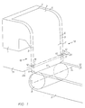
- a coater comprising a coating head 1 of the slide-hopper type that is arranged for applying a layer of liquid coating composition 2 to a moving web 3 by curtain coating.
- the hopper is supplied with coating composition through a manifold (not illustrated) and has an elongate discharge slot 4 from which the coating composition flows over a slide surface 5 unto a lip 6 from which it falls freely downwardly in the form of a curtain 7.
- the hopper extends transversely the path of travel of a web 3 to be coated, the path being determined by a backing roller 8.
- Means is provided, not illustrated, for controlling the correct web speed, the lateral postion, and the web tension.
- Edge guides 18 are provided near both lateral ends of lip 6 that are in adherent contact with the edges of the free-falling curtain 7 and thereby keep the curtain stretched in the transverse direction until it contacts the web 3 on a transverse line 17, the coating line.
- the edge guides have an upper, stationary section 9, a hinge 10 and a lower displaceable, pivotable in this case, section 11. In the operative position, the upper 9 and the lower section 11 of the edge guides are in contact with the curtain and form a straight line. Due to constructive reasons a small gap 19 between the upper 9 and lower 11 section has to be taken into account. This gap has to be smaller than approximately 1 mm, otherwise the curtain will not make properly contact with the lower edge section 11 of the guides 18 and will contract due to surface tension. It is surprising that the curtain 7 can narrow this gap 19 without giving rise to any disturbance.
- the coating is subjected to controlled temperatures and humidities to effect setting and drying of the coated layers (not illustrated).
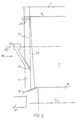
- Figure 2 is a view of the curtain coater in the non-operative position.
- a stable and uniform curtain has to be obtained.
- a displaceble interceptor 13 intercepts the entire curtain 7 and evacuates the liquid coating compostion into a tray, such as tray 15.
- Hinges 10 allow the lower section 11 of the edge guides 18 to be pivoted around an axis 20. The axis runs parallel with the axis 14 of the web-supporting roller 8, or the swinging occurs in a plane normal to the axis 14 of the web supporting roller 8.
- the interceptor 13 slides or pivots from underneath the curtain 7, the curtain impinging now on the moving web 3, the displacable sections 11 of the edge guides 18 turning back in their vertical positions, guiding the curtain over its full length.
- the coater is in an operative position and is able to coat the surface of the web 3 in a uniform way.
- Interceptor 13 can be made out of a strong flexible light-weight material, such as plastic or a polyester foil, the leading end 26 being strengthenend by a sharp metallic knife.
- EP 0 344 745 describes other possible geometries for the leading end 26 of this interceptor 13, it describes also the importance of the geometry of this leading end 26.
- FIGs 3,4 and 5 are views of a preferred embodiment of a curtain coater.
- a coating operation starts with a curtain coater in a non-operative position as in figure 4.
- the stationary section 9 of the edge guides 18 is connected with the lateral ends of a lip 6 of a hopper 1.
- the connection can be made in a fixed way, although it is preferable to construct this connection in such a way that it can be broken quite easily.
- a magnetic or adhesive connection that can be broken by a simple mechanical force allows the edge guides 18 or at least the stationary sections 9 to be thrown away when anything should hit the edge guide 18. For instance, if the web tears laterally, the loose ends can damage the edge guide and/or the coater if they are strongly fixed to the hopperlip 6.
- the lower displaceble section 11 of the edge guide 18 is pivoted in a forward position around a hinge 10. The swinging occurs in a plane normal to the axis of the web-supporting roller 8.
- the lower section 11 of the edge guide 18 is displaced in order to allow a curtain interceptor 13 to be positioned underneath the upper section 9 of the edge guide 18 and beyond the coating line 17, this is the line where a free falling liquid curtain should hit the web 8 for the first time.
- Two elongate lateral guides 22, placed at both lateral ends, allow the curtain interceptor 13 to glide from an intercepting position (fig. 4) towards a non-intercepting postion (fig. 3). In this embodiment the movement is produced with a pneumatic system 23. Other mechanical means can be used to perform the same operation.
- the start procedure begins by supplying the hopper 1 with a coating compostion through a manifold (not illustrated).
- the coating composition flows over the slide surface 5 unto the lip 6 from which it falls freely downwardly on the curtain interceptor 13, and into a catch tray 15.
- the operator tries to form a uniform layer or a plurality of superimposed layers constituting one composite layer on the slide surface 5. This may be done in a rather artisanal way, based on the experience of the operator.
- the uniform layer(s) have to form a curtain which extends from one edge guide towards the other, therefore the operator uses his hands and/or a little stick to stretch the curtain and to bring it in contact with the edge guide.
- an auxiliary liquid 24 provided between the edge guides 18 and the curtain 7 ameliorates the stability of the contact between the curtain 7 and the guide 18.
- the auxiliary liquid is dosed through a discharge opening 25 in section 9 of edge guide 18.
- a controller gives a signal to the pneumatic system 23 which pulls the curtain interceptor 13 in its non-intercepting position guided by the elongate lateral guides 22.
- the lower section 11 of the edge guide 18 is pivoted back in its vertical position whereby the edge of this lower section 11 that will make contact with the curtain forms a straight line with the corresponding egde of the upper section 9 of the edge guide.
- This swinging is also performed by a pneumatical system (not illustrated) and initiated by the controller.
- the curtain 7 and the auxiliary liquid 24 immediately narrows the gap 19 between the upper section 9 and the lower section 11 of the edge guide 18.
- the curtain 7 falls now on the moving web 3, producing a photographic element.
- an edge interceptor is described allowing to coat uniformly while leaving marginal portions of the web uncoated. This feature solves the problem of non-uniformities of the coating at edges, or the problem of thick edge portions, if the full width of the curtain is applied to the moving web.
- an edge interceptor 16 as described in said European Patent specification is connected to the lower section 11 of the edge guide 18.
- An edge catch tray 21 collects a small amount of the curtain liquid together with the auxiliary liquid 24. It is also possible to connect other means for reducing thick edge portions, such as described in US-A 4 830 887 or US-A 3 508 947 to this lower section 11 of the edge guide 18.
- the controller activates the pivoting of the lower section 11 of the edge guides 18.
- the lower section 11 of edge guide 18 is displaced from its vertical position (fig. 3) towards its raised position (fig. 4).
- the pneumatic system 23 pushes the curtain interceptor 13 in its intercepting position.
- the free falling curtain is gathered via the interceptor 13 in a catch tray 15. The operator can now take the neccessary measures in order to stop or to restart the coating without the web 3 being contaminated.
- the displacement of at least a section of the edge guides can occur in any direction such as in a direction which is opposite to the direction of advance of the travelling web, and is not limited to pivoting.
- a section of the edge guides or the entire edge guide can also slide or pivot about an axis that is not in a plane normal to the axis of the web supporting roller.
- the hinges of the edge guides can be connected at the hopper so that the entire edge guides are displaceble.
- the edge guides can be constructed as a telescope so that the displacement consist in a sliding of one section into another.
- the edge guide can also be constructed out of a elastic material that is flexed away by any means in order to let the edge interceptor pass underneath.
- the adjusting of the edge guides need not only occur by pneumatic means, but hydraulic, electrical and other driving means can be used.
Landscapes
- Chemical & Material Sciences (AREA)
- Engineering & Computer Science (AREA)
- Materials Engineering (AREA)
- Physics & Mathematics (AREA)
- General Physics & Mathematics (AREA)
- Coating Apparatus (AREA)
- Application Of Or Painting With Fluid Materials (AREA)
Claims (5)
- Ein Vorhangbeschichter zum Beschichten einer Bahn (3) mit wenigstens einer Schicht aus einer flüssigen Gießzusammensetzung (2), der eine bahntragende Walze (8) zum Transportieren der Bahn (3), einen Trichter (1) zur Bildung eines freifallenden Vorhangs (7) aus der flüssigen Gießzusammensetzung (2), der sich quer von der Bahn (3) in einer Position erstreckt, an der die Bahn (3) auf der bahntragenden Walze (8) unterstützt wird, Anleger (18) zum seitlichen Führen des fallenden Vorhangs (7), und einen versetzbaren Interzeptor (13) zum eventuellen Auffangen des fallenden Vorhangs (7),
dadurch gekennzeichnet, daß die breite des Interzeptors (13) größer ist als der Abstand zwischen den Anlegern (18), und daß wenigstens ein Teil (11) der Anleger (18) versetzt werden kann, so daß der Interzeptor (13) seine auffangende Position einnehmen kann. - Ein Vorhangbeschichter nach Anspruch 1, dadurch gekennzeichnet, daß die Anleger (18) einen oberen (9), gerätefesten Bereich und einen unteren (11), versetzbaren Bereich hat.
- Ein Vorhangbeschichter nach Anspruch 1 oder 2, dadurch gekennzeichnet, daß der versetzbare Bereich (11) der Anleger (18) in einer normal zur Achse der bahntragenden Bahn (8) liegenden Ebene rund eine Achse (20) gedreht werden kann.
- Ein Vorhangbeschichter nach Anspruch 1, dadurch gekennzeichnet, daß das Anlegen mittels einer Hilfsflüssigkeit (24) durchgeführt wird.
- Ein Vorhangbeschichter nach Anspruch 1, dadurch gekennzeichnet, daß ein Mittel zum Verringern der dicken Randportionen an den Anlegern (18) angeschlossen wird.
Priority Applications (4)
| Application Number | Priority Date | Filing Date | Title |
|---|---|---|---|
| EP91201538A EP0520091B1 (de) | 1991-06-18 | 1991-06-18 | Vorhangbeschichter |
| DE69115470T DE69115470T2 (de) | 1991-06-18 | 1991-06-18 | Vorhangbeschichter |
| US07/895,692 US5330797A (en) | 1991-06-18 | 1992-06-09 | Curtain coater with displaceable edge guides and method |
| JP4183070A JPH07178364A (ja) | 1991-06-18 | 1992-06-16 | カーテンコーター |
Applications Claiming Priority (1)
| Application Number | Priority Date | Filing Date | Title |
|---|---|---|---|
| EP91201538A EP0520091B1 (de) | 1991-06-18 | 1991-06-18 | Vorhangbeschichter |
Publications (2)
| Publication Number | Publication Date |
|---|---|
| EP0520091A1 EP0520091A1 (de) | 1992-12-30 |
| EP0520091B1 true EP0520091B1 (de) | 1995-12-13 |
Family
ID=8207724
Family Applications (1)
| Application Number | Title | Priority Date | Filing Date |
|---|---|---|---|
| EP91201538A Expired - Lifetime EP0520091B1 (de) | 1991-06-18 | 1991-06-18 | Vorhangbeschichter |
Country Status (4)
| Country | Link |
|---|---|
| US (1) | US5330797A (de) |
| EP (1) | EP0520091B1 (de) |
| JP (1) | JPH07178364A (de) |
| DE (1) | DE69115470T2 (de) |
Families Citing this family (11)
| Publication number | Priority date | Publication date | Assignee | Title |
|---|---|---|---|---|
| US5382292A (en) * | 1993-07-28 | 1995-01-17 | Eastman Kodak Company | Edge guide lubricating fluid delivery apparatus |
| US5338359A (en) * | 1993-11-03 | 1994-08-16 | Eastman Kodak Company | Hopper preparation pan with edge walls |
| JP4746894B2 (ja) * | 2005-03-14 | 2011-08-10 | ボイス ペ−パ− パテント ゲ−エムベ−ハ− | 塗工装置 |
| JP5239008B2 (ja) * | 2007-07-13 | 2013-07-17 | ボイス パテント ゲーエムベーハー | 塗工機の塗工幅調整装置 |
| JP5228226B2 (ja) * | 2007-07-20 | 2013-07-03 | ボイス パテント ゲーエムベーハー | 感熱紙の製造装置 |
| DE102007000778A1 (de) * | 2007-09-27 | 2009-04-02 | Voith Patent Gmbh | Auftragsvorrichtung und Verfahren zum Betreiben einer Auftragsvorrichtung |
| US8789492B2 (en) * | 2008-07-15 | 2014-07-29 | Awi Licensing Company | Coating apparatus and method |
| JP5169571B2 (ja) * | 2008-07-22 | 2013-03-27 | 株式会社リコー | カーテン塗布方法及び装置 |
| EP2147724B1 (de) | 2008-07-22 | 2012-06-20 | Ricoh Company, Ltd. | Vorhangbeschichtungsvorrichtung |
| JP5938980B2 (ja) * | 2011-03-31 | 2016-06-22 | 株式会社リコー | カーテン塗布方法及びカーテン塗布装置 |
| EP3342928A1 (de) | 2016-12-29 | 2018-07-04 | Valmet Technologies Oy | Vorhangapplikationsvorrichtung |
Family Cites Families (6)
| Publication number | Priority date | Publication date | Assignee | Title |
|---|---|---|---|---|
| GB1559701A (en) * | 1976-05-26 | 1980-01-23 | Ciba Geigy Ag | Curtain coating |
| DE3300150A1 (de) * | 1983-01-04 | 1984-07-05 | Agfa-Gevaert Ag, 5090 Leverkusen | Verfahren und vorrichtung zur stabilisierung von frei fallenden fluessigkeitsvorhaengen |
| EP0176632B1 (de) * | 1984-10-05 | 1988-01-07 | Agfa-Gevaert N.V. | Verfahren und Apparat zur Vorhangbeschichtung |
| JP2562941B2 (ja) * | 1988-06-02 | 1996-12-11 | 富士写真フイルム株式会社 | 塗布装置 |
| WO1990000939A1 (en) * | 1988-07-20 | 1990-02-08 | Eastman Kodak Company | Curtain coating edge control method and apparatus |
| US5017408A (en) * | 1990-08-08 | 1991-05-21 | Eastman Kodak Company | Curtain coating start/finish method and apparatus |
-
1991
- 1991-06-18 DE DE69115470T patent/DE69115470T2/de not_active Expired - Fee Related
- 1991-06-18 EP EP91201538A patent/EP0520091B1/de not_active Expired - Lifetime
-
1992
- 1992-06-09 US US07/895,692 patent/US5330797A/en not_active Expired - Fee Related
- 1992-06-16 JP JP4183070A patent/JPH07178364A/ja active Pending
Also Published As
| Publication number | Publication date |
|---|---|
| JPH07178364A (ja) | 1995-07-18 |
| EP0520091A1 (de) | 1992-12-30 |
| US5330797A (en) | 1994-07-19 |
| DE69115470T2 (de) | 1996-08-01 |
| DE69115470D1 (de) | 1996-01-25 |
Similar Documents
| Publication | Publication Date | Title |
|---|---|---|
| EP0520091B1 (de) | Vorhangbeschichter | |
| US3930464A (en) | Apparatus for applying a coating composition onto a web | |
| US4135477A (en) | Curtain coating apparatus | |
| CA1316774C (en) | Curtain-coating start-up method and apparatus | |
| JPH0570507B2 (de) | ||
| JPH07500531A (ja) | 分離塗膜パッチを形成するためのダイコータ | |
| EP0176632B1 (de) | Verfahren und Apparat zur Vorhangbeschichtung | |
| JPH0639331A (ja) | カーテンコーター | |
| EP0168986B1 (de) | Vorrichtung zum Beschichten mit mindestens einer Schicht und Verfahren zur Betreibung dieser Vorrichtung | |
| US4331713A (en) | Process and apparatus for the continuous coating of a sheet article, particularly a web of paper or paperboard | |
| JPH02233172A (ja) | 塗工装置及び巻取紙塗布方法 | |
| JPH05208159A (ja) | カーテンコーティング方法及びその装置 | |
| WO1990001179A1 (en) | Curtain coating method and apparatus | |
| US5755881A (en) | Apparatus for removing material from a coated moving web and coating apparatus using such apparatus | |
| US4359964A (en) | Air knife coater with pivoted lip | |
| JPH0330862A (ja) | 塗布装置 | |
| US6024797A (en) | Method and apparatus for controlling coat-weight profile | |
| US4963397A (en) | Paper coating system and method | |
| US5076200A (en) | Paper coating system and method | |
| JP3784070B2 (ja) | 縞状にコーティングするためのインサート | |
| JP5228226B2 (ja) | 感熱紙の製造装置 | |
| US6066208A (en) | Apparatus for coating a continuously moving web | |
| JP3861436B2 (ja) | 塗工装置 | |
| US4324609A (en) | Humidifier arrangement for a travelling hydrophilic web | |
| US5914155A (en) | Method and applicator for direct or indirect application of a liquid or pasty coating medium onto a traveling material web, notably of paper or cardboard |
Legal Events
| Date | Code | Title | Description |
|---|---|---|---|
| PUAI | Public reference made under article 153(3) epc to a published international application that has entered the european phase |
Free format text: ORIGINAL CODE: 0009012 |
|
| AK | Designated contracting states |
Kind code of ref document: A1 Designated state(s): AT BE CH DE DK ES FR GB GR IT LI LU NL SE |
|
| RBV | Designated contracting states (corrected) |
Designated state(s): BE DE FR GB IT NL |
|
| 17P | Request for examination filed |
Effective date: 19930505 |
|
| 17Q | First examination report despatched |
Effective date: 19930714 |
|
| GRAA | (expected) grant |
Free format text: ORIGINAL CODE: 0009210 |
|
| AK | Designated contracting states |
Kind code of ref document: B1 Designated state(s): BE DE FR GB IT NL |
|
| PG25 | Lapsed in a contracting state [announced via postgrant information from national office to epo] |
Ref country code: IT Free format text: LAPSE BECAUSE OF FAILURE TO SUBMIT A TRANSLATION OF THE DESCRIPTION OR TO PAY THE FEE WITHIN THE PRESCRIBED TIME-LIMIT;WARNING: LAPSES OF ITALIAN PATENTS WITH EFFECTIVE DATE BEFORE 2007 MAY HAVE OCCURRED AT ANY TIME BEFORE 2007. THE CORRECT EFFECTIVE DATE MAY BE DIFFERENT FROM THE ONE RECORDED. Effective date: 19951213 |
|
| REF | Corresponds to: |
Ref document number: 69115470 Country of ref document: DE Date of ref document: 19960125 |
|
| ET | Fr: translation filed | ||
| PGFP | Annual fee paid to national office [announced via postgrant information from national office to epo] |
Ref country code: FR Payment date: 19960521 Year of fee payment: 6 |
|
| PGFP | Annual fee paid to national office [announced via postgrant information from national office to epo] |
Ref country code: DE Payment date: 19960523 Year of fee payment: 6 Ref country code: GB Payment date: 19960523 Year of fee payment: 6 |
|
| PGFP | Annual fee paid to national office [announced via postgrant information from national office to epo] |
Ref country code: BE Payment date: 19960529 Year of fee payment: 6 |
|
| PGFP | Annual fee paid to national office [announced via postgrant information from national office to epo] |
Ref country code: NL Payment date: 19960630 Year of fee payment: 6 |
|
| REG | Reference to a national code |
Ref country code: GB Ref legal event code: 746 Effective date: 19960606 |
|
| PLBE | No opposition filed within time limit |
Free format text: ORIGINAL CODE: 0009261 |
|
| STAA | Information on the status of an ep patent application or granted ep patent |
Free format text: STATUS: NO OPPOSITION FILED WITHIN TIME LIMIT |
|
| REG | Reference to a national code |
Ref country code: FR Ref legal event code: D9 Free format text: CORRECTION |
|
| 26N | No opposition filed | ||
| PG25 | Lapsed in a contracting state [announced via postgrant information from national office to epo] |
Ref country code: GB Free format text: LAPSE BECAUSE OF NON-PAYMENT OF DUE FEES Effective date: 19970618 |
|
| PG25 | Lapsed in a contracting state [announced via postgrant information from national office to epo] |
Ref country code: BE Effective date: 19970630 |
|
| BERE | Be: lapsed |
Owner name: AGFA-GEVAERT N.V. Effective date: 19970630 |
|
| PG25 | Lapsed in a contracting state [announced via postgrant information from national office to epo] |
Ref country code: NL Effective date: 19980101 |
|
| GBPC | Gb: european patent ceased through non-payment of renewal fee |
Effective date: 19970618 |
|
| PG25 | Lapsed in a contracting state [announced via postgrant information from national office to epo] |
Ref country code: FR Free format text: LAPSE BECAUSE OF NON-PAYMENT OF DUE FEES Effective date: 19980227 |
|
| NLV4 | Nl: lapsed or anulled due to non-payment of the annual fee |
Effective date: 19980101 |
|
| PG25 | Lapsed in a contracting state [announced via postgrant information from national office to epo] |
Ref country code: DE Free format text: LAPSE BECAUSE OF NON-PAYMENT OF DUE FEES Effective date: 19980303 |
|
| REG | Reference to a national code |
Ref country code: FR Ref legal event code: ST |
|
| REG | Reference to a national code |
Ref country code: FR Ref legal event code: ST |